6601B矩阵通讯协议 DEMO使用说明
6601B与硬录主机通讯协议(OEM版)
6601B与计算机通讯协议(OEM版V2.0)一.简介:6601B是PC与视频矩阵通讯的缓冲和中转设备。
本协议仅为PC与6601B通讯协议中基本操作控制部分,由此可以实现对矩阵基本功能的控制。
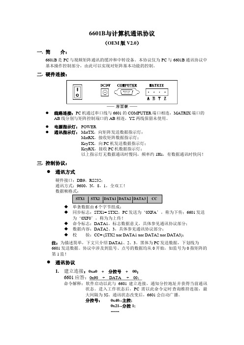
二.硬件连接:●线路连接:PC机通过串口线与6601的COMPUTER端口相连,MATRIX端口的AB线分别与矩阵控制端口的AB相连,YZ两线保留未使用。
●电源指示灯:POWER●通讯指示灯:MatTX,向矩阵发送数据指示灯;MatRX,接收矩阵数据指示灯;KeyTX,向PC机发送数据指示灯;KeyRX,接收PC机数据指示灯;以上指示灯无数据通讯时慢闪,频率约1Hz,有数据通讯时快闪!三.控制协议:●通讯方式硬件接口:DB9,RS232;通讯方式:9600,N,8,1,全双工!◆单条数据由6个字节组成:◆同步标志:STX1= STX2,PC发送为‘0XFA’,称为下传;6601发送为‘0XF0’,称为为上传!◆命令标志:DATA1,标志数据意义,具体参见通讯协议部分;◆数据内容:DATA2、3,具体参见通讯协议部分;◆校验:CC= (STX2 xor DATA1 xor DATA2 xor DATA3);注:为描述简单,下文只介绍DATA1、2、3。
黑体为PC发送数据,下划线为6601发送数据。
协议中涉及到监号、点号的数据均从0开始,如监号为0指矩阵的第1监!●通讯协议1.建立连接:0xa0+分控号+00;6601应答:0x90+DATA +00;命令解释:软件启动以此与6601建立连接,通知分控地址并获得当前通讯状态。
进入工作状态后,PC需以此命令定时查询维持连接,最大间隔为3S。
通讯状态改变后,6601会自动广播。
分控号:0x40--主控;0x21--分控1;……0x27--分控7;所有控制设备的分控号不能相同!DATA:0x01--通讯正常;0x02--矩阵忙;0x03--矩阵不在线;0x04--6601复位;2.6601请求授权监:DATA + 0xE8 + 00;下传分控授权监:0x6F+0xE8 +监号;(可以多条连续)命令解释:分控命令,分控软件启动或收到6601请求下传授权监的命令后下传授权监信息以取得对该监的控制权。
M-BUS通信协议说明及应用
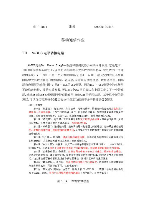
电工1001 张睿0990*******移动通信作业TTL—M-BUS电平转换电路M-BUS是由Dr. Horst Ziegler教授和德州仪器公司共同开发的,它是建立ISO-OSI考模型基础之上,以便充分利用现有大多数的网络协议,使之成为一个开放的系统。
M - BUS 不是一个完整的网络,它的4 - 6OSI 层是空的并且不处理网络中大多数的任务,如传输层、会话层,因此只提供物理层、数据链路层、网络层和应用层的功能,图-1 是M - BUS的OSI模型。
因为ISO - OSI模型中的高级层不能修改地址、波特率等参数,所以在7个OSI层的旁边和上面又定义了一个管理层,地址254或255被保留用于管理物理层,地址253用于网络层。
基于这个新的管理层,可以直接管理每个OSI层去执行指定功能而不必严格遵循OSI模型。
图-1 M - BUS的OSI模型M - BUS 系统是一个带有通讯控制主机的多级系统,它是由主机和一定数量的从机(终端设备) 通过两根电缆连接而成,所有的从机都并联连接在总线上,并可通过总线获得所需电源。
为了实现数据和能量的共同传输,M - BUS总线上的bit 流传输采用两种调制方式:电压调制和电流调制。
TTL—M-BUS的转换电路如图-2 所示,主要包括发送器和接收器两个部分。
图-2 TTL—M-BUS电平转换总体电路1、发送器M-BUS发送端:由集中器向终端仪表终端传输的信号采用电压值的变化来表示,即集中器向终端仪表终端发送的数据码流是一种电压脉冲序列,用+36 V 表示逻辑“1”,用+24V表示逻辑“0”。
在稳态时电平保持“1”状态。
如图-3 所示为集中器向终端发送的数据码流图。
图-3 集中器向终端发送的数据码流图图-3 所示的集中器向终端发送的数据码流图的发送波形在图-4 中可以得到结果。
图-4 中当“TXD”发送数据时由Q2为前端驱动级,可以得到Q2集电极产生一个与TXD波形相反且幅度为0-36V的波。
6601设备BSC侧数据定义说明

6601设备BSC侧数据定义说明
1、小区频点设置说明
使用6601设备在设置小区频点时需注意,最大最小频率间隔不得超过75,且该设备不支持EGSM频点,最大发射功率为42。
2、基站软件本版设置
6601设备需配置B0704R029E
3、基站容量配置说明
目前6601设备支持4/4/4,8/8/8两种主要配置,当然4/8/4,8/4/8等配置也可支持,由于6601所带RRU为四密度载频,且每个小区最多带2个RRU,所以对于单个小区最小配置为4,最大配置为8,如果为8配置,则使用主从TG同步,每个小区8套载频需要跨机架定义。
由于DU之间通过光纤通信,无需设置时延,BSC侧数据无需定义为TF主从(Master-Slave)同步。
以现网师惠邻里中心51135,8/8/8配置为例,MO数据如下:。
海康威视 FELCOM12 通信系统说明书

Tech Date Box 1 - FELCOM12 Display Wt: 24 lbs. Dim: 20"x 17"x 21"Part No.Description Quantity Yes Remarks 1IB581LCD Terminal Display with CPU 12000-138-599BTC-5100 PS/2 Keyboard 13000-055-405Blank Floppy Disk 1.44M 14004-437-270IB581 Software Floppy Disk 1updated periodically Box 2 - FELCOM12 Comm. Unit Wt: 27 lbs. Dim: 18"x 17"x 16"Part No.Description Quantity Yes Remarks 1IC212Communication Unit BDU 12000-802-080Tapping Screw 63000-861-937Knob Bolt 24004-437-990Hanger Assembly 15100-087-911Hanger Washer 26OME-561-30Z Operator's Manual 17OSE-561-30Z Operator's Guide 1Box 2 Con't. - FELCOM12 Antenna Unit "Part No.Description Quantity Yes Remarks 1IC112Antenna Unit Felcom 121Box 2 Con't. - FELCOM12PC Inst Kit Wt: 30 lbs. Dim: 13"x 13"x 28"Part No.Description Quantity Yes Remarks 1IC302Distress Alert Unit 22IC303Telex Indicator 1Not in FELCOM12PC 3000-108-138Ground Wire 1sub 000-043-2594000-112-543Power Cable 1"5000-127-108DB9-DB9 Cable 1"6000-802-084Tapping Screw 4"7100-217-010Label INMAR 1"8100-237-670Hook Loop Fastener 4"9100-237-680Hook Loop Fastener 4"10100-248-051Label Keyboard 1"11100-248-060Label CSD 1"12000-122-400Power Cable 1sub 004-438-00013000-508-663Conn SRCN6A16-10P 1"14590-300-310Copper Strap 1.2M 1"15000-802-080Tapping Screw 6sub 000-043-34416000-861-937Knob Bolt 2"17100-087-911Hanger Washer 2"18004-437-990Hanger Assembly 1"19000-108-424Crimp Lug FV2-33sub 004-438-010 (X 3)20000-508-662Conn SRCN6A16-7P 3"21000-538-113Crimp Lug FV1.25-315"22000-802-079Tapping Screw 3 x 1012"23000-802-393Hole Plug 3"24000-808-099Bushing 3"25100-208-272Distress Cover 2sub 000-041-294PACKING LIST FOR RC1515IC212IC112FELCOM12INST IB581/12Tech Date Box 2 Con't. - FELCOM12PC Installation Kit "Part No.Description Quantity Yes Remarks 26100-248-770Distress Label 2sub 000-041-29427Distress Alert Procedures 128Precautions-Inmarsat C Felcom12129Precautions-IC302130OSC-561-31Z Simple E-Mail Felcom10/11/12131Creating Internet Message 132Activation Registration Form 133IME-561-30Z Installation Manual 1Box 2 Con't. - Cable Wt: 14 lbs. Dim: 10"x 13"x 14"Part No.Description Quantity Yes Remarks 1000-138-86730M Coax Cable 150M available 2000-133-058Conn. N-P-5DFB-113000-139-927Cable Assembly 16S023814000-566-000Grounding Wire 15000-835-526Self Bounding Tape 16000-854-118Adhesive 17000-862-182Hex Bolt M6 x 12 SUS30418000-862-129Hex Bolt M6 x 16 SUS30449100-251-820Antenna Mounting Pipe 110*000-117-599*50M with 8D-FB-CV Conn.**sub for 30M Serial No.2560-Checked By:Box 3 - FS1562/15Wt: 32 lbs. Dim: 17"x 14"x 20"Part No.Description Quantity Yes Remarks 1FS1562/15DIS 250W SSB Radiotelephone 1w/ remote plug2OME-557-22Z Operator's Manual 13IME-557-22Z Installation Manual 14005-922-690Hanger 15000-800-601Knob Bolt 26100-087-911Hanger Washer 27100-100-390Knob Washer 28000-800-414Tapping Screw 69000-864-129Flat Washer 610000-139-033Microphone 111000-130-430Power Cable 112000-113-348Grounding Wire 113000-549-015Fuse/Glass 20A 1PACKING LIST FOR RC1515FELCOM12INST FS1562/15For Internal Use Only FELCOM12CBLTech Date Box 3 (con't)- AT1560"Part No.Description Quantity Yes Remarks 1AT1560250W Automatic Coupler 12000-113-360Coaxial RF Cable 10M 120M available 3000-130-484Coupler Control Cable w/ Connector 120, 30M available 4000-113-3482M Ground Wire 15000-130-472Rubber Pipe Seal 16000-805-494Tapping Screw M5x1647000-572-187Copper Strap 04S408011Serial No.3503 -Checked By:Box 4 - DP6 Modem Unit Wt: 13 lbs. Dim: 9"x 13"x 22"Part No.Description Quantity Yes Remarks 1DP-6NBDP Modem Unit 12OME-561-00Z Operator's Manual 13IME-561-00Z Installation Manual 14OSE-561-00Z Operator's Guide 15590-300-310Copper Strap 1.2M 16000-867-553Tapping Screw M5 x 2547000-864-128Flat Washer M548000-120-946DB25 Connector 29000-112-543Power Cable Assembly 3M 110000-508-663Connector SCRN6A16-10P 1Box 5 - DP6 LCD Terminal Wt: 24 lbs. Dim: 20"x 17"x 21"Part No.Description Quantity Yes Remarks 1IB581Monochrome LCD Terminal 1with DP6 on CPU 2000-138-599Mini Keyboard with Cable & Plug 13000-055-405Blank Floppy Disk 1.44M 1unformatted4004-447-090DP6 Software "Floppy Disk"15000-108-138Grounding Wire 2M 16000-112-543Power Cable Assembly 3M 17000-127-108Data Cable DB25-DB25 "5M"18000-802-084Tapping Screw M6 x 2049100-217-010BCM Label 110100-237-670Hook Loop Fastener 1411100-237-680Hook Loop Fastener 2412100-248-050Label 113100-248-060Label "Compass Safe Distance"1AT1560For Internal Use Only DP6MAIN IB581/6PACKING LIST FOR RC1515Tech Date Serial No.3516 - Checked By:Box 6 - DSC60 Terminal ReceiverPart No.Description Quantity Yes Remarks 1DSC60DSC Terminal / Watch Receiver 12OME-562-80Z Operator's Manual 13IME-562-80Z Installation Manual 14005-950-250Mounting Bracket 15005-948-710Mouunting Knob Assembly 2sub 005-950-1806000-800-414Tapping Screw M6 x 205"7000-864-129Flat Washer M65"8000-144-917External Speaker with Cord & Plug 1Serial No.2596 - Checked By:Box 7 & 8 - FM8500 (x 2)Wt: 17 lbs. Dim: 9"x 15"x 18"Part No.Description Quantity Yes Remarks 1FM8500Main Unit 12OME-560-30Z Operator's Manual 13IME-560-30Z Installation Manual 14Distress Alert Procedure 15000-138-000Handset Bracket Assembly 16100-274-720Distress button Cover Assembly 17000-108-368Plug FM14-4P 18000-111-537Plug FM14-5P 19000-116-185Plug FM14-6P 110000-113-345Plug FM14-7P 111000-500-346Plug HS16P-2112005-992-690Bracket Assembly 113000-800-601Knobs 214000-800-414Tapping Screw 6 6 x 2015000-864-129Flat Washer 6M616100-087-911Hanger Washer 217100-100-390Knob Washer 2on knob 18OSE-560-30Z Operator's Guide 1Serial No.1375 - Checked By:Box 9 & 10 - PP510 (x 2)Wt: 27 lbs. Dim: 18"x 17"x 16"Part No.Description Quantity Yes Remarks 1PP51024V Dot Matrix Printer 12PP5-100-002Paper Carriage Assy 13000-133-029Ribbon Cassette 14004-434-410Printer Fixtures (2pc)1sub 000-043-257FM8500For Internal Use Only DSC60For Internal Use Only For Internal Use Only PP510PACKING LIST FOR RC1515Tech Date Serial No.1375 - Checked By:Box 9 & 10 (con't) - PP510 (x 2)"Part No.Description Quantity Yes Remarks 5Carrier Mount 2"6Knurled Screws for Mounting 2"7Hook Loop Fastener Strip 2"8000-802-081Tapping Screw 4"9100-217-010"BCM" Sticker 1"10100-222-480"Compass Safe" Sticker 1"11000-132-249Power Cable Assy 112RC1-500-019Cable 6 ft. Centronics 36p>DB25113AYT214Roll Paper 114OME-508-00Z Operator's Manual 1Box 11 - PR850A Wt: 86 lbs. Dim: 16"x 20"x 20"Part No.Description Quantity Yes Remarks 1PR805A Rectifier AC to 24 VDC 1w/ auto switchover 2Label Voltage Selection (100-240V)13Lug Solder Type 24Lug Crimp 35Tapping Screw 66Washer Flat 67Voltage Alternation List 1Box (Crate) 12 - FUSA1500Wt: 296 lbs. Dim: 32"x 36"x 47"Part No.Description Quantity Yes Remarks 1FUSA1500A3 Pre-Wired Rack w/ meter 1with NMEA distributor 2Shore-Based Maintenance Certificate 1& incl mic bracket 3"E Meter" Owner's Manual 14IME-GMD-10Z Console Installation Manual 15RC1-500-034ATC Fuse 3A 36RC1-500-014Bulb 5W 24V 17RC1-500-060Connector PL2592FELCOM12KIT (Installed in IC212 - in Box 1)Part No.Description Quantity Yes Remarks 1006-969-200GPS Module GN74NNCC NE 12RF Mini Coax 138 pin VH Pigtail (to CPU J8)1rev 6/03PR850A FUSA1500FELCOM12KIT For Internal Use Only PP510PACKING LIST FOR RC1515。
CP1E Modbos通讯格式

CP1E Modbus-RTU通讯格式00001 00003 00004 2103从站+ 功能吗+ 字节数+ 地址+ 数据写数据是在D1300____D1349开始的通道;读数据是在D1350____D1399开始的通道。
D1300 从站地址完整命令为0106000113388+CRC16D1301 功能代码06H D1300 00001D1302 通讯数据字节数D1301 00006D1303 写入寄存器编号D1302 00004D1304 数据D1303 00001D1304 1388D1302是从D1303__D1349后面所写的通讯数据的字节数,所以写的时候可以先空出,把通讯数据都写好后再写地址,这个地址是我们PLC为了计算校验多出的地址,所以写Modbos数据的格式来顺序编写就可以,但校验可以不用写。
CP1W_____CIF11设置2、3、5、6打ON PLC设置就设置串口网关,波特率、数据格式与变频器一致即可。
CQM1H与PC的编程下载线接线图PLC PC2----------------------------23----------------------------34----------------------------85----------------------------79----------------------------54---6短接有两个比较简单的问题请各位高人指点下~ 我用的是CP1E的PLC和3G3JZ之间用485通讯第一个问题是PLC向变频器的10个不连续的地址写东西那么我需要按MODBUS通讯格式写10组#1#10......么?第二个问题是如果从变频器读10组值而变频器的寄存器地址又不连续那么我还得按MODBUS通讯格式写10组#1#3......么?而且我怎么确定变频器中的地址和我PLC映射区的地址之间的关系?首先如果变频器地址不连续,无论是读还是写都会出错的建议你用#10指令一个一个写,读也是一个一个的读串口1写入频率:D1200=变频器站号D1201=#10 命令D1202=&07 从D32203开始的字节数D1203=#2102 频率地址D1204=&1 写入个数D1205高8位=#02 辅助字节数=D32204*2 D1205低8位=写入频率值的高8位D1206的高8位=写入频率值的低8位响应码在D1250开始详细介绍可以参考CP1E Soft手册会比较清楚①接线:PLC 变频器RDA- ───── R+RDB+ ───── R-其中变频器的R+和S+短接,R-和S-短接。
安全伯力护套模块说明书
ArmorBlock 4 Input Module2Publication 1792-5.1 – October 1996European Union Directive ComplianceIf this product is installed within the European Union or EEA regions and has the CE mark, the following regulations apply.EMC DirectiveThis apparatus is tested to meet Council Directive 89/336/EECElectromagnetic Compatibility (EMC) using a technical construction file and the following standards, in whole or in part:•EN 50081-2EMC – Generic Emission Standard, Part 2 –Industrial Environment•EN 50082-2EMC – Generic Immunity Standard, Part 2 –Industrial EnvironmentThe product described in this manual is intended for use in an industrial environment.Low Voltage DirectiveThis apparatus is also designed to meet Council Directive 73/23/EEC Low V oltage, by applying the safety requirements of EN 61131–2Programmable Controllers, Part 2 – Equipment Requirements and Tests.For specific information that the above norm requires, see the appropriate sections in this manual, as well as the following Allen-Bradley publications:•Industrial Automation Wiring and Grounding Guidelines,publication 1770-4.1•Automation Systems Catalog, publication B1113ArmorBlock 4 Input Module Publication 1792-5.1 – October 1996Install Y our ArmorBlock ModuleInstallation of the ArmorBlock module consists of:•setting the node address in the ArmorBlock module •mounting the ArmorBlock module •connecting the wiring•communicating with your module •configuring the parametersSet the Node AddressEach ArmorBlock comes with its internal program set for node address 63. To set the node address, you need the following:•host computer with DeviceNet Manager Software (or similarconfiguration software tool)•1770-KFD RS-232 module (or similar interface)•suitable cables to connect the 1770-KFD to your module and to connect the 1770-KFD to your host computer Set the node address to meet your system requirements as follows:1.Set up a system (as shown below) to communicate with your ArmorBlock module.Power from 9V DC Power-Supply AdapterRS-232 moduleDeviceNet Manager software1770-KFDArmorBlock 4 Input Module4Publication 1792-5.1 – October 1996ing DeviceNet Manager Software, go online using the “SetupOnline Connection” selection on the utility pulldown menu.3.The DeviceNet Driver selection screen appears.Select the driver for your application and click onto go online.5ArmorBlock 4 Input Module Publication 1792-5.1 – October 19965.The bar at the bottom of the screen will tell you when you go online.ArmorBlock 4 Input Module6Publication 1792-5.1 – October 1996Mount the ArmorBlock ModuleMount the block module directly to the machine or device. Complete mounting dimensions are shown below. Note that the block dimensions allow direct connection of a T-port tap (cat. no. 1485P-P1N5-j ) to the DeviceNet connector. (Refer to publication 1485-6.7.1 for cabling details.)The ArmorBlock module has a sloping top and a gap at the rear to allow water or other liquids to run off during washdowns. The flow through the gap prevents buildup of debris under the block.Preferred mounting position is with the microconnectors pointing down. However, the block can be mounted in any orientation.7ArmorBlock 4 Input Module Publication 1792-5.1 – October 1996Mounting DimensionsBlock dimensions allow T -port tap connection directly onto connectorFor washdown installations,or excessively moist areas,mount block with micro connectors down.ArmorBlock 4 Input Module8Publication 1792-5.1 – October 1996Connect the Wiring to the ArmorBlock ModuleThe block module uses quick disconnect, screw-on style connectors for:•I/O input wiring•the DeviceNet connectorDeviceNet mini connectorseal unused portsMicro plugs are included with your module. Use these plugs to cover and seal unused ports.Pinout diagrams for these connectors are shown below.!ATTENTION: All connectors must be securelytightened to properly seal the connections against leaks and maintain NEMA 4X and 6P requirements.9ArmorBlock 4 Input Module Publication 1792-5.1 – October 1996Connecting the Input WiringConnect input wiring to the micro connectors which screw into mating connectors on the side of the block.Make connections as shown below.Pin 1 = Sensor Source Voltage Positive Pin 3 = Negative/Return Pin 4 = SignalPin 2 = Not used Connecting the DeviceNet WiringConnect DeviceNet wiring to the 5-pin mini connector on the end of the block. Connections are shown below.DeviceNet Mini Connector Pin 1 = Drain (Bare)Pin 2 = V+ (Red)Pin 3 = V– (Black)(View into pins)Pin 4 = CAN–HI (White)Pin 5 CAN–LO (Blue)Note: Colors are DeviceNet standardArmorBlock 4 Input Module10Publication 1792-5.1 – October 1996Communicate with Your ArmorBlock ModuleThis ArmorBlock module acts as a slave in a master/slave environment.It is both a “polled device” and a “change of state device.”When configured as a polled device, a master initiates communication by sending its polled I/O message to the ArmorBlock module. The 4input module scans the inputs and fault bit producing a response that reflects their status.When configured as a “change of state” device, productions occur when an input changes or an input source voltage fault occurs. If neither has occurred within the “expected packet rate,” a heartbeat production occurs. This heartbeat production tells the scanner module that the ArmorBlock module is alive and ready to communicate.S = Sensor source voltage faultConfigure Y our Armor Block Module Offline Using the DeviceNet Manager Configuration ToolTo configure your ArmorBlock module offline:•add the device to the network•set the parameters for the device•save the parameters to a fileNote: You cannot actually configure your device offline. You can set and save the parameters to a file for downloading to the device when you go online.Adding a Device to the Networkscreen, click on “discrete I/O” inthe device type box.Then click on the desired ArmorBlock device.Configure your Device ParametersAfter adding the devices to the network, you must configure them. You have 2 choices:•highlight the device, and click on the.Configuring the ParametersDefault settings for the 4 input module are:1.Double click on the parameter you want to change.The software displaysthe parameter number,name and value.Read only parameters(designated by an R)are also shown.Parameters can beviewed all at once,configuration only, orI/O only.The parameter screen appears.2.Click on the radio button. To cancel any changes, click on. A screen similar to this will appear. To continue, click onbutton. This returns you to the device configuration screen.You can save these parameters to a file for downloading to the device when online, or print them to a text file for hard copy use.Saving to a File1.To save those parameters to a file, click on thebutton.A screen similar to the following will appear.2.Choose the file name, file type (.TXT), directory and drive to whichyou want to save the file.3.Click on theto bring up pertinent information concerning the device configuration you are selecting.Additionally, help is available on each parameter screen by clicking on2.The configuration screen for your selected driver appears. You can:•set the node address•set the data rate•select the interface adapter serial port•set the interface adapter baud rate3.After setting the parameters, click on theOnlineAdd the Device to the Networkscreen, click on “discrete I/O” inthe device type box.Then click on the desired ArmorBlock device.4.Click once on the device you wish to configure on the project screenand choose5.Load parameters.If you want to load parameters Choose From a fileFrom default settings6.Modify the parameter.If you want to ChooseModify a parameterYou see a screen similar to this one.T o save these settings to the device,chooseYou can view parameters online by clicking onAny changes that occur for a parameter will be reflectedon the screen.7.Save parameters to a file, to the device, or print to a file.If you want to ChooseSave parametersto a fileYou see this screen.Print to a fileYou see this screen.Select the drive, file type, directory, and file name to which youwould like to save and choose8.To exit from the Enhanced Configuration screen,click onMonitoring Parameters OnlineYou can monitor parameters at the Device Configuration screen or at the selected parameter screen.The start monitor button on the Device Configuration screen allows you to monitor all of the parameters online. To monitor parameters:Click on the4.Click on the button to stop monitoring.Reset FaultsThere are various ways to reset faults on an ArmorBlock module.•cycle power to the module by disconnecting, then reconnecting the DeviceNet connector•use the Reset Faulted I/O feature on the parameter screen•use the explicit message program control featureNote:This module contains a circuit to protect the DeviceNet power supply from short circuits in an attached sensor or sensor cable. If you connect a sensor while the module is powered, the surge current produced by the sensor can cause themodule to fault. This operation is normal. If this occurs, reset the module.Reset Faults Online Using the Parameter ScreenTo reset faults online, return to the network screen and proceed as follows:1.Click on the faulted device.2.Then click on the ConfigureDevice button.The device configuration screen appears. Select the Reset Faulted I/Oparameter.After selectingthe parameter, click on themodify parameter button.The configuration screen for the selected parameter appears.2.Then click on theOK button to apply.3.You will be returned tothe configuration screen.Click on ”Save to Device”to apply the change.1.Click on the desired selection to reset.Reset Faults using Explicit Message Program ControlYou can also reset inputs using the Explicit Message Program Control feature on the Scanner module master. Refer to the specific scanner publications for information on using this feature.The format for the reset explicit message transaction block must contain 6 words as shown below:Configure Y our Armor Block Module Using EDS Files Current versions of DeviceNet Manager software include ArmorBlock module support. If you are using a version of DeviceNet Manager software that does not include ArmorBlock module Electronic Data Sheets (EDS) files in its library, you can use the following information to create the file.If you are using a configuration tool other than DeviceNet Manager, you can also use the following information to create the EDS file. (Note: This EDS file was current at the time of printing. Contact your nearest district office for information on later files.)$ Electronic Data Sheet for Armor Block I/O (1792–IB4)[File]DescText=”1792–IB4 Armor Block I/O EDS File”;CreateDate = 04–18–96;CreateTime = 12:00:00;ModDate = 09–17–96;ModTime = 16:00:00;Revision = 2.1;$ EDS revision.[Device]VendCode = 1;VendName = ”Allen–Bradley Company, Inc.”;ProdType = 7;ProdTypeStr = ”General Purpose Discrete I/O”;ProdCode = 1024;MajRev = 2;MinRev = 1;ProdName = ”Armor Block I/O 4 input”;Catalog = ”1792–IB4”;UCMM = 0;$ UCMM is not supported.[IO_Info]Default = 0x0001;$ The default I/O type is polled I/O.PollInfo =0x0001,$ Polled I/O device.1,$ Input1 entry is the default input connection.1;$ Output1 entry is the default output connection.Input1 =1,$ The size in bytes that this connection produces.0,$ All bits of this connection are significant.0x0001,$ Only Polled I/O is compatible.”IB4 Production Data”,$ Name of Connection.6,$ Path length.”20 04 24 0D 30 03”,$ Path to I/O Production Assembly.$$$$$$$$$$ Help string $$$$$$$$$$$”This connection contains data from inputs at bits 0–3 and the sensor source voltage status at bit 7.”;[ParamClass]MaxInst = 9;$ 4 configurable and 5 read–only parameters Descriptor = 0x09;$ Stub param instances in eeprom.CfgAssembly = 0x66;$ The config assembly is instance #102 of assy obj. [Params] $$$$$$$$$$$$$$$$$$$$$$$$$$$$$$$$$$$$$$$$$$$$$$$$$$$$$$$$$$$$$$$$$$$$$ $$$$$$$$$$Param1 =$ Disable Autobaud0,$ reserved6,$ Link Path Size”20 03 24 01 30 64”,$ Link Path to disable autobaud attribute.0x0002,$ No support for settable path, scaling, scaling links,$ or real time update of value. Value is gettable and$ Settable. Enumerated strings are supported.4,$ Data Type – boolean1,$ Data Size”Autobaud”,$ Parameter Name””,$ Units String$$$$$$$$$$ Help string $$$$$$$$$$$”Enable takes effect after next powerup. Disable is required to set fixed baud rate, no power cycle is required.”,0,1,0,$ Min, Max, and Default values1,1,1,0,0,0,0,0,0;$ Not Used $$$$$$$$$$$$$$$$$$$$$$$$$$$$$$$$$$$$$$$$$$$$$$$$$$$$$$$$$$$$$$$$$$$$$ $$$$$$$$$$Param2 =$ Input filter Off_to_On Delay selection0,$ reserved6,$ Link Path Size”20 0F 24 02 30 01”,$ Link Path to param instance. The param instance$ decodes the enumerated parameter into engineering$ units (micro seconds).0x0002,$ No support for settable path, scaling, scaling links,$ or real time update of value. Value is gettable and$ Settable. Enumerated strings are supported.2,$ Data Type – unsigned int2,$ Data Size – (in bytes)”Off–to–On Delay”,$ Parameter Name”ms”,$ Units String$$$$$$$$$$ Help string $$$$$$$$$$$”Signal must be present for this delay period before module detects the change.”,0,4,0,$ Min, Max (max enumeration #), and Default values 1,1,1,0,0,0,0,0,0;$ Not Used $$$$$$$$$$$$$$$$$$$$$$$$$$$$$$$$$$$$$$$$$$$$$$$$$$$$$$$$$$$$$$$$$$$$$ $$$$$$$$$$Param3 =$ Input filter On_to_Off Delay selection0,$ reserved6,$ Link Path Size”20 0F 24 03 30 01”,$ Link Path to param instance. The param instance$ decodes the enumerated parameter into engineering$ units (micro seconds).0x0002,$ No support for settable path, scaling, scaling links,$ or real time update of value. Value is gettable and$ Settable. Enumerated strings are supported.2,$ Data Type – unsigned int2,$ Data Size – (in bytes)”On–to–Off Delay”,$ Parameter Name”ms”,$ Units String$$$$$$$$$$ Help string $$$$$$$$$$$”Signal must be present for this delay period before module detects the change.”,0,4,0,$ Min, Max (max enumeration #), and Default values 1,1,1,0,0,0,0,0,0;$ Not Used $$$$$$$$$$$$$$$$$$$$$$$$$$$$$$$$$$$$$$$$$$$$$$$$$$$$$$$$$$$$$$$$$$$$$ $$$$$$$$$$Param4 =$ Reset Faulted I/O0,$ reserved6,$ Link Path Size”20 0F 24 04 30 01”,$ Link Path to param instance.0x0002,$ No support for settable path, scaling, scaling links,$ or real time update of value. Value is gettable and$ Settable. Enumerated strings are supported.8,$ Data Type – unsigned short int1,$ Data Size – (in bytes)”Reset Faulted I/O”,$ Parameter Name””,$ Units String$$$$$$$$$$ Help string $$$$$$$$$$$”This resets the voltage supplied to sensors. A reset will only be accepted if a fault exists.”,0,1,0,$ Min, Max (max enumeration #), and Default values 1,1,1,0,0,0,0,0,0;$ Not Used $$$$$$$$$$$$$$$$$$$$$$$$$$$$$$$$$$$$$$$$$$$$$$$$$$$$$$$$$$$$$$$$$$$$$ $$$$$$$$$$Param5 =$ Input 1 value0,$ reserved6,$ Link Path Size”20 08 24 01 30 03”,$ Link Path to Input 1 value attribute.0x0030,$ No support for settable path, scaling, or scaling$ links.$ Value is gettable only. Enumerated strings are not$ supported.8,$ Data Type – unsigned short int1,$ Data Size – (in bytes)”Input 1 Value”,$ Parameter Name””,$ Units String$$$$$$$$$$ Help string $$$$$$$$$$$”This parameter is the current value of Input 1.”,0,1,0,$ Min, Max, and Default values1,1,1,0,0,0,0,0,0;$ Not Used $$$$$$$$$$$$$$$$$$$$$$$$$$$$$$$$$$$$$$$$$$$$$$$$$$$$$$$$$$$$$$$$$$$$$ $$$$$$$$$$Param6 =$ Input 2 value0,$ reserved6,$ Link Path Size”20 08 24 02 30 03”,$ Link Path to Input 2 value attribute.0x0030,$ No support for settable path, scaling, or scaling$ links.$ Value is gettable only. Enumerated strings are not$ supported.8,$ Data Type – unsigned short int1,$ Data Size – (in bytes)”Input 2 Value”,$ Parameter Name””,$ Units String$$$$$$$$$$ Help string $$$$$$$$$$$”This parameter is the current value of Input 2.”,0,1,0,$ Min, Max, and Default values1,1,1,0,0,0,0,0,0;$ Not Used $$$$$$$$$$$$$$$$$$$$$$$$$$$$$$$$$$$$$$$$$$$$$$$$$$$$$$$$$$$$$$$$$$$$$ $$$$$$$$$$Param7 =$ Input 3 value0,$ reserved6,$ Link Path Size”20 08 24 03 30 03”,$ Link Path to Input 3 value attribute.0x0030,$ No support for settable path, scaling, or scaling$ links.$ Value is gettable only. Enumerated strings are not$ supported.8,$ Data Type – unsigned short int1,$ Data Size – (in bytes)”Input 3 Value”,$ Parameter Name””,$ Units String$$$$$$$$$$ Help string $$$$$$$$$$$”This parameter is the current value of Input 3.”,0,1,0,$ Min, Max, and Default values1,1,1,0,0,0,0,0,0;$ Not Used $$$$$$$$$$$$$$$$$$$$$$$$$$$$$$$$$$$$$$$$$$$$$$$$$$$$$$$$$$$$$$$$$$$$$ $$$$$$$$$$Param8 =$ Input 4 value0,$ reserved6,$ Link Path Size”20 08 24 04 30 03”,$ Link Path to Input 4 value attribute.0x0030,$ No support for settable path, scaling, or scaling$ links.$ Value is gettable only. Enumerated strings are not$ supported.8,$ Data Type – unsigned short int1,$ Data Size – (in bytes)Publication 1792-5.1 – October 1996”Input 4 Value”,$ Parameter Name””,$ Units String$$$$$$$$$$ Help string $$$$$$$$$$$”This parameter is the current value of Input 4.”,0,1,0,$ Min, Max, and Default values1,1,1,0,0,0,0,0,0;$ Not Used $$$$$$$$$$$$$$$$$$$$$$$$$$$$$$$$$$$$$$$$$$$$$$$$$$$$$$$$$$$$$$$$$$$$$ $$$$$$$$$$Param9 =$ Input status0,$ reserved6,$ Link Path Size”20 1D 24 01 30 05”,$ Link Path to Dicrete Input Group status attribute.0x0032,$ No support for settable path, scaling, or scaling$ links.$ Value is gettable only. Enumerated strings are$supported.8,$ Data Type – unsigned short int1,$ Data Size – (in bytes)”Input Status”,$ Parameter Name””,$ Units String$$$$$$$$$$ Help string $$$$$$$$$$$”This parameter is the current status of the sensor source voltage.”,0,1,0,$ Min, Max, and Default values1,1,1,0,0,0,0,0,0;$ Not Used[Groups]Group1=”Configuration”,3,1,2,3;Group2=”I/O”,6,4,5,6,7,8,9;[EnumPar]Param1=”Enable”,”Disable”;Param2=”0 ms”,”2 ms”,”4 ms”,”8 ms”,”16 ms”;Param3=”0 ms”,”2 ms”,”4 ms”,”8 ms”,”16 ms”;Param4=”Nothing Selected”,”Reset Sensor Source V oltage”;Param9=”Healthy”,”Faulted”;Publication 1792-5.1 – October 1996Troubleshoot with the IndicatorsThe ArmorBlock I/O module has 3 types of indicators:•Mod/Net status indicator•Input fault indicator•individual I/O status indicatorsNote:This module contains a circuit to protect the DeviceNet power supply from short circuits in an attached sensor or sensor cable. If you connect a sensor while the module ispowered, the surge current produced by the sensor can cause the module to fault. This operation is normal. If this occurs, reset the module (page 25).Publication 1792-5.1 – October 1996Specifications4 Input Module – Cat. No. 1792-IB4Publication 1792-5.1 – October 19964 Input Module – Cat. No. 1792-IB4This product has been tested at an Open DeviceNet V endor Association, Inc. (ODV A) authorized independent test laboratory and found to comply with ODVA Conformance Test Software V ersion FT 1.2/1.0.Publication 1792-5.1 – October 1996Publication 1792-5.1 – October 1996Publication 1792-5.1 – October 1996Supersedes publication 1792-5.1 – November 1995PN955126–02Copyright 1996 Allen-Bradley Company , Inc. Printed in USAWorldwide representation.Argentina • Australia • Austria • Bahrain • Belgium • Brazil • Bulgaria • Canada • Chile • China, PRC •Colombia • Costa Rica • Croatia • Cyprus • Czech Republic • Denmark • Ecuador • Egypt • El Salvador •Finland • France • Germany • Greece • Guatemala • Honduras • Hong Kong • Hungary • Iceland • India •Indonesia • Ireland •Israel • Italy • Jamaica • Japan • Jordan • Korea • Kuwait • Lebanon • Malaysia •Mexico • Netherlands •New Zealand • Norway • Pakistan • Peru • Philippines • Poland • Portugal •Puerto Rico • Qatar • Romania • Russia–CIS • Saudi Arabia • Singapore • Slovakia • Slovenia • South Africa, Republic • Spain • Sweden •Switzerland • T aiwan • Thailand • T urkey • United Arab Emirates •United Kingdom • United States • Uruguay • V enezuela • Y ugoslaviaAllen-Bradley Headquarters, 1201 South Second Street, Milwaukee, WI 53204 USA,Tel: (1) 414 382-2000 Fax: (1) 414 382-4444。
捷控高清混插矩阵说明书

.高清矩阵信号切换系统PROFESSIONAL MATRIX SWITCHERS SYSTEM用户手册在使用前,请仔细阅读本用户手册目录一、包装说明 ............................................................................................................................................... - 5 -二、矩阵系统说明...................................................................................................................................... - 5 -2.1 矩阵功能的概述 ......................................................................................................................... - 5 -2.2 数字高清矩阵的分类................................................................................................................ - 5 -2.2.1伯爵II全无缝高清混插矩阵....................................................................................... - 5 -技术规格...................................................................................................................................... - 6 -输入信号卡.................................................................................................................................. - 9 -输出信号卡.................................................................................................................................. - 9 -型号系列.................................................................................................................................... - 10 -技术参数.................................................................................................................................... - 10 -2.2.2数字高清全无缝DVI矩阵(混合全无缝输出卡)........................................... - 12 -产品特征.................................................................................................................................... - 12 -技术规格.................................................................................................................................... - 15 -2.2.3 数字高清全无缝HDMI矩阵(混合全无缝输出卡)...................................... - 17 -产品特征.................................................................................................................................... - 17 -技术规格.................................................................................................................................... - 19 -三、安装连接 ............................................................................................................................................. - 21 -3.1 矩阵主机与机柜的安装 ....................................................................................................... - 21 -3.2 RS-232通信接口的连接方法............................................................................................ - 22 -3.3 RJ45型网线插头的连接方法............................................................................................. - 22 -3.4 伯爵II高清混插智能矩阵后面板示意图及接线说明................................................ - 24 -3.5 数字高清全无缝DVI矩阵后面板示意图及接线说明................................................ - 25 -3.6 数字高清全无缝HDMI矩阵后面板示意图及接线说明 ........................................... - 25 -四、操作说明 ............................................................................................................................................. - 26 -4.1 面板按键控制方式................................................................................................................... - 26 -4.2.1 亚像素级调试技术...................................................................................................... - 27 -4.2 RS-232协议控制指令系统.................................................................................................... - 28 -4.3 应用软件使用说明................................................................................................................... - 30 -4.3.1 《MatrixTool》软件介绍 .......................................................................................... - 30 -4.3.2 软件的启动.................................................................................................................... - 30 -4.3.3 《MatrixTool》的操作............................................................................................... - 30 -4.4 手机安卓软件的使用.............................................................................................................. - 33 -4.4.1 界面操作......................................................................................................................... - 33 -五、系统应用连接示例图 ...................................................................................................................... - 35 -5.1 伯爵系列高清混插智能矩阵系统连接图(以HD1818为例) ...................................... - 35 -5.2 数字高清DVI矩阵(以HD DVI1818为例) ....................................................................... - 36 -5.3 数字高清HDMI矩阵系统连接图(以HDMI1818为例) ..................... 错误!未定义书签。
ws660说明书

目录前言 ................................................................ 3一般安全要求 ........................................................ 4快速操作指南 ........................................................ 5操作手册 ................................................................ 6一、功能简介 ................................................ 6二、产品特点 ................................................ 7三、技术参数 ................................................ 7四、前面板示意图 ........................................ 9指示灯 .................................................... 9拨码开关 ............................................ 10按钮开关 ............................................ 13五、台式后面板示意图............................. 14电源输入 ............................................ 14E1接口 ............................................... 15ETHERNET(以太网)接口................. 15六、底板示意图 ........................................ 16两位拨码开关 .................................... 16壁挂孔 ................................................ 16七、机框前面板示意图............................. 17网管卡 ................................................ 17功能卡 ................................................ 17电源板 ................................................ 171八、机框后面板示意图............................. 18地址开关 ............................................ 18级联口 ................................................ 18九、做线方式 ............................................ 19十、安装步骤 ............................................ 20故障诊断及排除 ................................................ 21典型组网方案 .................................................... 22术语解释 ............................................................ 252前言数据通信标准经协商一致、发表并为众人遵循。
晓波电子桥接矩阵产品说明书

YBS20005 THRU YBS2010Bridge RectifiersFeatures●UL recognition, file #E313149● Ideal for automated placement● High surge current capability● Meets MSL level 1, per J-STD-020, LF maximumpeak of 260 °CTypical ApplicationsGeneral purpose use in AC/DC bridge full wave rectification forSMPS, lighting ballaster, adapter, battery charger, homeappliances, office equipment, and telecommunicationapplications.Mechanical Data●P ackage: YBSMolding compound meets UL 94 V-0 flammabilityrating, RoHS-compliant, Halogen-free●Terminals:Tin plated leads, solderable perJ-STD-002 and JESD22-B102●Polarity: As marked on body ■Maximum Ratings (T a=25℃ Unless otherwise specified)PARAMETER SYMBOL UNIT YBS20005YBS2001YBS2002YBS2004 YBS2006 YBS2008YBS2010 Device marking code YBS20005YBS2001YBS2002YBS2004 YBS2006 YBS2008YBS2010 Repetitive peak reverse voltage V RRM V 50 100 200 400 600 800 1000 Average rectified output current@60Hz sine wave, R-load, Tc=110℃I O A 2.0Surge(non-repetitive)forward current@60H Z sine wave, 1 cycle, T j=25℃I FSM A 75Current squared time@1ms≤t<8.3ms Tj=25℃,Rating of per diodeI2t A2s 23Storage temperature T stg ℃-55 ~+150Junction temperature T j ℃-55 ~+150■Electrical Characteristics(T a=25℃ Unless otherwise specified)PARAMETER SYMBOL UNIT TESTCONDITIONSYBS20005YBS2001YBS2002YBS2004YBS2006YBS2008YBS2010 Maximum instantaneous forwardvoltage drop per diodeV F V I FM=1.0A 1.00Maximum DC reverse currentat rated DC blocking voltage per diode @ VRM=VRRM I RRM μATj=25℃5Tj=100℃100COMPLIANTRoHS■Thermal Characteristics (T a=25℃ Unless otherwise specified)PARAMETER SYMBOL UNIT YBS20005YBS2001YBS2002YBS2004YBS2006 YBS2008YBS2010Thermal Resistance Between Junctionand Ambient,RθJ-A℃/W55.0 BetweenJunction andLeadRθJ-L 15.0BetweenJunction andCaseRθJ-C 10.0■Ordering Information (Example)PREFERED P/N PACKINGCODEUNIT WEIGHT(g)MINIIMUMPACKAGE(pcs)INNER BOXQUANTITY(pcs)OUTER CARTONQUANTITY(pcs)DELIVERY MODEYBS20005-YBS2010 F1 Approximate0.2183000 6000 42000 13” reel ■Characteristics(Typical)`FIG1:Io-Tc Curve1.01.5AverageForwardOutputCurrent(A)Case Temperature (℃)0.40.60.8 1.0 1.2 1.40.010.020.05FIG3: Forward Voltage0.112460.5InstantaneousForwardCurrent(A)Instantaneous Forward Voltage (V)020*********0.010.11.010100FIG4:Typical Reverse CharacteristicsInstantaneousReverseCurrent(uA)Percent of Rated Peak Reverse Voltage (%)12510205010015FIG2:Surge Forward Current CapabilityNumber of Cycles3045607590105PeakForwardsurgeCurrent(A)■ Outline Dimensions■ Suggested pad layoutDim Min P1 9.15 P2 7.10 Q1 1.80 Q22.00YBSDim Min Max A 5.005.20B 6.50 6.70 C7.20 7.40 D 7.90 8.60 E 2.90 3.10 F 0.04 0.08 G0.27 0.40 H 1.30 1.50 I 0.95 1.15 J0.70 1.05DisclaimerThe information presented in this document is for reference only. Yangzhou Yangjie Electronic Technology Co., Ltd. reserves the right to make changes without notice for the specification of the products displayed herein to improve reliability, function or design or otherwise.The product listed herein is designed to be used with ordinary electronic equipment or devices, and not designed to be used with equipment or devices which require high level of reliability and the malfunction of with would directly endanger human life (such as medical instruments, transportation equipment, aerospace machinery, nuclear-reactor controllers, fuel controllers and other safety devices), Yangjie or anyone on its behalf, assumes no responsibility or liability for any damages resulting from such improper use of sale.This publication supersedes & replaces all information previously supplied. For additional information, please visit our website http:// , or consult your nearest Yangjie’s sales office for further assistance.。
XD6710B产品使用手册说明书

XD6710B产品使用手册文件版本: V22.2.24XD6710B采用工业通用标准RS485总线 MODBUS-RTU协议接口,方便接入PLC,DCS等各种仪表或系统,用于监测温度,湿度等状态量。
内部使用了较高精度的传感内核及相关器件,确保产品具有较高的可靠性与卓越的长期稳定性, 可定制RS232、RS485、CAN、4-20mA、DC0~5V\10V、ZIGBEE、Lora、WIFI、GPRS、NB-IOT等多种输出方式。
技术参数外形尺寸产品接线任何错误接线均有可能对产品造成不可逆的损坏。
请在断电的情况下认真按如下方式接线,请在断电线的情况下,按图示方法进行接线,如果产品本身无引线,线芯颜色供参考。
应用方案典型应用RS485型:通讯协议产品使用RS485 MODBUS-RTU标准协议格式,所有操作或回复命令都为16进制数据。
设备出厂时默认设备地址为1,默认波特率为 9600,8,n,1。
1. 读取数据( 功能码0x03)问询帧(十六进制),发送举例:查询1#设备1个数据,上位机发送命令:01 03 00 00 00倍率为100,则真实值为121/100=1.21,其它以此类推。
当值为负数时,数据是以补码的形式上传的。
通常通过判断值是否大于32768的方法来判断正负。
当接收到的值大于32768时即为负值,前值减去65535除以100即为真实值。
比如接收到的温度数据为62999(十六进制F617),则真实值=(62999-65535)/100=-25.36。
2. 常用数据地址表3 读取与修改设备地址(1)读取或查询设备地址若不知道当前设备地址、且总线上只有一个设备时,可以通过命令FA 03 00 66 00 01 71为设备地址的寄存器。
对于正确的查询命令,设备会响应,比如响应数据为:01 03 02 00 01 79 84,其格式解(2)更改设备地址效,此时用户需要同时将自己软件的查询命令做相应更改。
ABB变频器RMBA-01 MODBUS模块设置方法
ABB变频器RMBA-01 MODBUS模块设置方
法
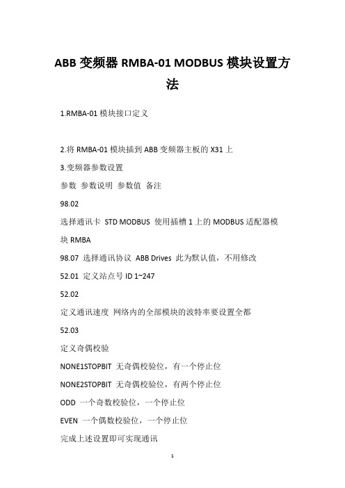
1.RMBA-01模块接口定义
2.将RMBA-01模块插到ABB变频器主板的X31上
3.变频器参数设置
参数参数说明参数值备注
98.02
选择通讯卡STD MODBUS 使用插槽1上的MODBUS适配器模
块RMBA
98.07 选择通讯协议ABB Drives 此为默认值,不用修改
52.01 定义站点号ID 1~247
52.02
定义通讯速度网络内的全部模块的波特率要设置全都
52.03
定义奇偶校验
NONE1STOPBIT 无奇偶校验位,有一个停止位
NONE2STOPBIT 无奇偶校验位,有两个停止位
ODD 一个奇数校验位,一个停止位
EVEN 一个偶数校验位,一个停止位
完成上述设置即可实现通讯
4.RMBA-01模块指示灯状态说明
RXD和TXD为绿色,WD/INIT为黄色
RMBA-01每收到1个信息就RXD闪耀一次
RMBA-01每发送1个信息就TXD闪耀一次
WD/INIT 指示灯:在传动单元通电后就开头发亮,直到传动单元配置完模块后才熄灭,假如黄色指示灯在模块配置胜利后再次发亮,可能是模块由于电源断电等缘由而需要重新配置。
假如配置完成后LED仍未熄灭,则可能
A:配置失败-关闭传动单元的电源并重新启动
B:模块硬件故障-确信38针连接器正确插入。
博世 B450 通信模块操作指南说明书
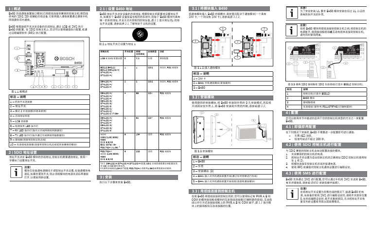
您可以使用本节中描述的适用于您的控制主机类型的方法之一来配置B450。
在下列情况下安装时,B450 不需要进一步配置即可进行通信:–无需 AES 加密。
–低信号延迟不超过 200 秒。
与 SDI2 兼容的控制主机会自动配置连接的模块。
1. 关闭兼容的控制主机的电源。
2. 将地址开关设置为适合控制主机的正确地址(SDI2 控制主机使用地址 1 或 2)。
3. 将模块连接至控制主机总线并接通电源。
4.使用 RPS 或键盘对控制主机通信设置进行编程设定。
B450 支持通过 SMS 进行配置。
您可以通过手机将 SMS 发送到 B450。
有关详细信息,请参阅《B450 安装和操作指南》。
使用提供的安装螺丝,将 B450 安装到外壳的 3 孔安装模式,然后将天线固定在外壳上。
将 B450 安装到外壳的内侧。
请参阅图 3.2。
标注 ― 说明1 ― B4502 ― 外壳3 ― 安装螺丝 (3)4 ― B44x 插入式手机通信装置天线(通过任何穿眼进行布线)5 ― B44x 插入式手机通信装置天线电缆(连接到通信模块)图 3.3:安装模块在将 B450 用缆线连接到控制主机时,您可以使用标记有 PWR、A、B 和COM 的模块接线板或模块的互连缆线连接器(已随附提供缆线)。
互连缆线以并行方式连接接线板上的 PWR、A、B 和 COM 端子。
图 1.1 指示模块上的接线板和互连连接器的位置。
执行以下步骤来安装 B450。
图 3.3:使用 SDI2 接线板或 SDI2 互连缆线(已显示 B5512 控制主机)。
标注说明1控制主机(已显示 B5512)2B450 模块3接线板缆线4互连缆线 (部件号:F01U079745)(已随附提供)标注 ― 说明1 ― SIM 卡2 ― B44x 手机通信模块(单独提供)3 ― B450将通信模块插入 B450 的插槽中,具体情况取决于通信模块(一个具有SIM 卡;一个则没有 SIM 卡)。
ABB-free home 电源 PS-M-64.1.1 (6201 640.1) 技术手册说明书
技术手册电源电源PS-M-64.1.1 (6201/640.1)1手册提示__________________________________________________________________ 4 2安全______________________________________________________________________ 52.1使用的标志 _________________________________________________________________ 52.2按规定使用 _________________________________________________________________ 62.3未按规定使用 _______________________________________________________________ 62.4目标人群/人员资质___________________________________________________________ 62.5责任和保修 _________________________________________________________________ 6 3环境______________________________________________________________________ 7 4产品说明__________________________________________________________________ 84.1供货范围 ___________________________________________________________________ 84.2型号概览 ___________________________________________________________________ 94.3功能说明 ___________________________________________________________________ 94.4电源设备概览 PS-M-64.1.1____________________________________________________ 9 5技术数据_________________________________________________________________ 105.1PS-M-64.1.1 概览___________________________________________________________ 105.2规格尺寸 __________________________________________________________________ 125.3接线图 ____________________________________________________________________ 125.4操作和显示元件____________________________________________________________ 13 6安装_____________________________________________________________________ 146.1有关安装的安全提示________________________________________________________ 146.2安装/装配__________________________________________________________________ 166.3电气连接 __________________________________________________________________ 176.4拆线 ______________________________________________________________________ 177调试_____________________________________________________________________ 18 8保养_____________________________________________________________________ 198.1清洁 ______________________________________________________________________ 19 9规划和应用提示___________________________________________________________ 209.1复位 ______________________________________________________________________ 209.2故障 ______________________________________________________________________ 20ABB-free@home®手册提示1手册提示仔细通读本手册并遵守列出的提示。
Binary HDMI 4x4矩阵开关说明书
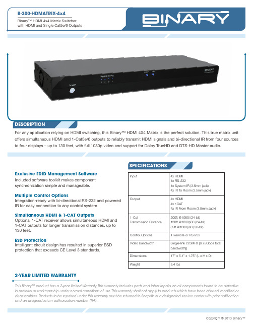
Input4x HDMI 1x RS-2321x System IR (3.5mm jack)4x IR To Room (3.5mm jack)Output4x HDMI 4x 1CAT4x IR From Room (3.5mm Jack)1-CatTransmission Distance 200ft @1080i (24-bit)130ft @1080p60 (24-bit)65ft @1080p60 (36-bit)Control Options IR remote or RS-232Video Bandwidth Single-link 225MHz [6.75Gbps total bandwidth]]Dimensions 17” x 5.1” x 1.75” (L x H x D)Weight5.4 lbs2-YEAR LIMITED WARRANTYThis Binary™ product has a 2-year limited Warranty. This warranty includes parts and labor repairs on all components found to be defective in material or workmanship under normal conditions of use. This warranty shall not apply to products which have been abused, modified or disassembled. Products to be repaired under this warranty must be returned to SnapAV or a designated service center with prior notification and an assigned return authorization number (RA).DESCRIPTIONFor any application relying on HDMI switching, this Binary™ HDMI 4X4 Matrix is the perfect solution. This true matrix unit offers simultaneous HDMI and 1-Cat5e/6 outputs to reliably transmit HDMI signals and bi-directional IR from four sources to four displays – up to 130 feet, with full 1080p video and support for Dolby TrueHD and DTS-HD Master audio.SPECIFICATIONSExclusive EDID Management Software Included software toolkit makes component synchronization simple and manageable.Multiple Control OptionsIntegration-ready with bi-directional RS-232 and powered IR for easy connection to any control systemSimultaneous HDMI & 1-CAT OutputsOptional 1-CAT receiver allows simultaneous HDMI and 1-CAT outputs for longer transmission distances, up to 130 feet.ESD ProtectionIntelligent circuit design has resulted in superior ESD protection that exceeds CE Level 3 standards.IN THE BOX(1) B-300-HDMATRIX-4x4 HDMI Matrix Switch (2) Rack ears for mounting (1) IR Remote(1) Power supply(12V 5A)(1) IR Adapter for Control Systems (1) User Manual(1) CD Rom containing Documentation, PCConfiguration Utility, Discrete IR Codes and Serial Protocol.SPECIFICATIONSTECHNICALProduct Type True 4x4 HDMI matrixHDMI compliance Full HD 1080P60, Deep Color (36bit),3D (1.4a 3D)HDCP compliance Version 2.0Video bandwidthSingle-link 225MHz [6.75Gbps total bandwidth]Video support1080p / 1080i / 720p /480p / 480i up to 36-bit color Audio supportMulti-Channel up to 7.1:Dolby TrueHD Dolby Digital Plus DTS-HD Master DTS-HD LPCMDolby Digital EX DTS-ES Dolby Digital DTS 2ch:PCMESD protectionESD: IEC 61000-4-2 Level 4 (15KV)Surge: IEC 61000-4-5Input4x HDMI 1x RS-2321x System IR (3.5mm jack)4x IR To Room (3.5mm jack)Output4x HDMI 4x 1CAT4x IR From Room (3.5mm Jack)1-CatTransmission Distance 200ft @1080i (24-bit)130ft @1080p60 (24-bit)65ft @1080p60 (36-bit)HDMI Input selection IR remote or RS-232IR remote control 21 button remote for Setup and OperationHDMI connector Type A [19-pin female]1CAT Connector RJ-45RS-232 connector 9-pin DB9 female Ethernet ConnectorN/AMECHANICALHousing Metal enclosure Dimensions (L x W x H)Switcher 17” x 5.1” x 1.75”Package21” x 10.4” x 3.1”Weight 5.4 lbsMounting 1RU rack-mount. Ears included Power supply 12 5A DC Power consumption 60 Watts [max]Operation temperature 32~104°F]Storage temperature -20~60°C -4~140°FRelative humidity 20~90% RH [no condensation]CertificationsCE,FCC, RoHs。
USB-RIM版本1B - 无线电接口模块说明书
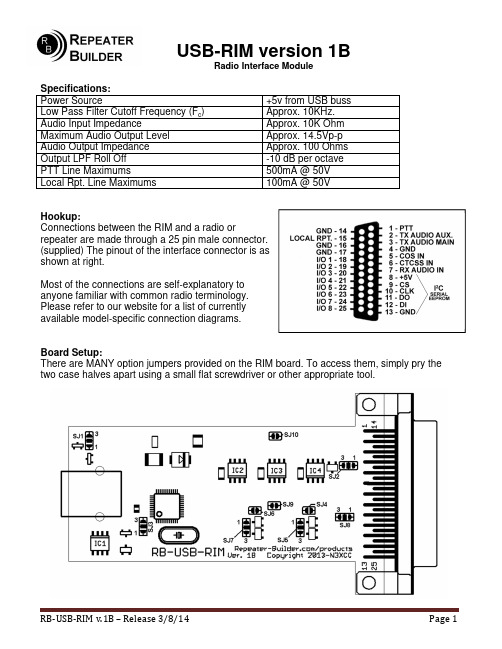
USB-RIM version 1BRadio Interface ModuleSpecifications:Power Source +5v from USB bussLow Pass Filter Cutoff Frequency (F c )Approx. 10KHz.Audio Input Impedance Approx. 10K OhmMaximum Audio Output Level Approx. 14.5Vp-pAudio Output Impedance Approx. 100 OhmsOutput LPF Roll Off -10 dB per octavePTT Line Maximums 500mA @ 50VLocal Rpt. Line Maximums 100mA @ 50VHookup:Connections between the RIM and a radio orrepeater are made through a 25 pin male connector.(supplied) The pinout of the interface connector is asshown at right.Most of the connections are self-explanatory toanyone familiar with common radio terminology.Please refer to our website for a list of currentlyavailable model-specific connection diagrams.Board Setup:There are MANY option jumpers provided on the RIM board. To access them, simply pry thetwo case halves apart using a small flat screwdriver or other appropriate tool.Board Setup: (continued)Some jumpers are “single” jumpers in that they are either “in” or “out.” Some jumpers have two positions. They are configured by soldering between EITHER the #1 pad –or- the #3 pad, NOT both. The only jumper where *ALL* pads may be connected is SJ8, the Rx input attenuator jumper.SJ1 – PTT Ground Reference – Dual position – Shipped in the ‘3’ positionSolder jumper SJ1 is used to select where the Push-to-Talk MOSFET obtains its ground. If the jumper is connected between the center and pad ‘1’, the PTT MOSFET will get its ground directly from the board. If the jumper is connected between the center and pad ‘3’, the PTT will get its ground from the ”PC Comms OK” output. Thus eliminating the possibility of the PTT being “stuck” low due to a PC USB communications failure.SJ2 – PC Comms OK Output Polarity – Dual position – Shipped not jumpedSolder jumper SJ2 is used to select the output polarity of the “Local Rpt.” output pin. This pin may be connected to signal a repeater’s internal controller that external PC controller communications have failed and is no longer in control. Most “all-in-one” type repeater boxes have this functionality. Consult your equipment owner’s manual or our model-specific hook-up sheet for more information.If the solder jumper is connected between the center and ‘1’, the “Local Rpt.” output pin will pull to ground when PC communications have failed. If the jumper is connected between the center and ‘3’, this pin will be pulled low when the RIM is successfully communicating with the PC.SJ3 – PC Comms OK Input Source Selection – Dual position – Shipped in the ‘1’ position Solder jumper SJ3 is used to select the input to the ”PC Comms OK” circuitry. For all AllStar based PC controllers, (ACID, XIPAR, etc.) this jumper should be installed from the center pad to the ‘1’ position. Some other PC based controllers (FreeStar) that use the CM119 IC’s GPIO1 pin will want this jumped between the center pad and position ‘3’.SJ4 – CTCSS Input Pull-up Enable – Single position – Shipped ‘open’Solder jumper SJ4 is used to connect a 10K pull-up resistor from 5V to the RIM’s CTCSS logic input. This is useful when the radio/repeater/controller’s CTCSS output is an “open collector” type output and will not source voltage. Short the pads of SJ4 to enable this pull-up.SJ5 – CTCSS Input Polarity Selection – Dual position – Shipped in the ‘1’ positionSolder jumper SJ5 is used to select the input polarity of the CTCSS circuitry. If the CTCSS output of your radio/repeater/controller’s CTCSS output provides voltage or is “open collector” when a valid tone is being received, jump from the center to the ‘1’ pad. If theradio/repeater/controller’s CTCSS output goes to ground when a valid tone is being received, jump from the center to the ‘3’ pad. Also see SJ4 above for other options.SJ6 – COS Input Pull-up Enable – Single position – Shipped ‘open’Solder jumper SJ6 is used to connect a 10K pull-up resistor from 5V to the RIM’s COS logic input. This is useful when the radio/repeater/controller’s COS output is an “open collector” type output and will not source voltage. Short the pads of SJ6 to enable this pull-up.Solder Jumpers: (continued)SJ7 – COS Input Polarity Selection – Dual position – Shipped in the ‘1’ positionSolder jumper SJ6 is used to select the input polarity of the COS circuitry. If the COS output of your radio/repeater/controller’s COS output provides voltage or is “open collector” when a valid tone is being received, jump from the center to the ‘1’ pad. If the radio/repeater/controller’s COS output goes to ground when a valid tone is being received, jump from the center to the ‘3’ pad. Also see SJ6 above for other options.SJ8 – RX Audio Input Attenuator – Multi position – Shipped not jumpedSolder jumper SJ8 is the ONLY jumper that may have ALL pads jumped, depending on the amount of input attenuation desired. Solder pad ‘1’ connects to a 10K resistor. Solder pad ‘3 connects to a 22K resistor. With these two resistor values in conjunction with the 22K input resistor, 4 values of attenuation are possible.Jumper configuration Net LossNo jumpers shorted 0dBPad ‘1’ shorted to center ~6dBPad ‘3’ shorted to center ~10dBPads 1&3 shorted to center ~12.5dBSJ9 – Main Audio Output Gain Reduction – Single position – Shipped ‘open’Solder jumper SJ9 shorts out a resistor in the feedback path of the final audio op-amp. This reduces the gain of the last amplifier stage from 2.5x down to 1x. This jumper (and associated gain reduction) *may* be needed when driving the microphone input of yourradio/repeater/controller’s audio chain. Consult your equipment owner’s manual or our model-specific hook-up sheet for more information.SJ10 – Auxiliary Audio Output Gain Reduction – Single position – Shipped ‘open’Same as above, but applies to the Auxiliary (secondary) audio output.。
LTE爱立信6601演示文稿

DU图片
我们通常用到得为DUG,所以这里只摘出DUG图Fra bibliotek大家进行学习。
DUG各个接口的功能: GPS:提供GPS同步信号 EC:用EC线将DU与MU的连接 LMTA:操作维护端口(OMT接口) LMTB:SITE LAN(基站局域网)接口 ETA/ETB:;两路传输接口:E1/T1 ESB:ESB总线接口(TG同步用) A-F:与RRUS的CPRI接口。
RRUS的地线的连接
RRUS-48V电源的连接
安装连到MU上的光纤
光纤是LC 头,接到1 口;2 口接级联
RRUS的级联
此处所讲的RRUS的级联是RRUS的联级连接
RF天线的连接
RRUS级联RX线的连接
6601常用配置连线
讲到6000的常用配置,则不得不讲下RBB RBB(radio building block无线构建模块) RBB[Tx] [Rx] _ [C] [V] :指的是一个DUG上 RBB构成。 TX:TX支路的数量 RX:RX支路的数量 C:CPRI链路的数量 V:version版本(不用深究)
爱立信RBS6601基站
陈伟
RBS6000基站描述
•
• • •
RBS6000基站的设计以支持大容量和多标准为基 本出发点。2010年推出的RBS6000系列基站主要 有2种类型: 室内宏站RBS6201 分布式基站RBS6601 RBS6000主要构成部分是数字处理单元 (Digital Unit)和射频单元(Radio Unit)。 数字处理单元主要包括基带信号处理模块及传 输接口;而射频单元是收发信机,完成射频信 号的处理。
RBB:12_1A
RBB:12_1A
典型的1X4的配置连接图,拓展到3X4配置。则只需要将3个RRUS通过 CPRI接口用光纤连接到同一个DUG上,其他不变。 此时,RRUS上光纤接都要接到各自的data1口,另一头分别按顺序接 DUG的A口、B口、C口
博睿BRMatrix矩阵切换器使用手册

第一章安全操作指南为确保设备可靠使用及人员的安全,在安装,使用和维护时,请遵守以下事项:1、系统接地系统必须有完善的接地,否则不仅造成信号干扰、不稳定或机械损坏,而且还可能因漏电引起人身事故。
切换矩阵的最终接地点应连接至真地,其接地电阻应小于5。
2、禁止改变原设计禁止更改本产品的机械和电气设计,禁止增添任何部件,否则生产厂家对由此所带来的危害性结果不负责任。
3、请勿使用两芯插头,确保设备的输入电源为 220V 50Hz的交流电。
4、机器内有交流 220V高压部件,请勿擅自打开机壳,以免发生触电危险。
5、不要将系统设备置于过冷或过热的地方。
6、设备电源在工作时会发热,因此要保持工作环境的良好通风,以免温度过高而损坏机器。
7、阴雨潮湿天气或长时间不使用时,应关闭设备电源总闸。
8、在下列操作之前,一定要将设备的交流电源线从交流供电电源插座上拔下:◆取下或重装设备的任何部件◆断开或重接设备的任何电器插头或其它连接9.非专业人士未经许可,请不要试图拆开设备机箱,不要私自维修,以免发生意外事故或加重设备的损坏程度。
10.不要将任何化学品或液体洒在设备上或其附近。
第二章产品简介2.1矩阵切换器此系列矩阵切换器, 是一款高性能的专业矩阵切换设备, 可用于切换音频,视频和VGA信号。
音频信号支持平衡和非平衡两种;视频信号支持复合视频、S-Video信号、RGB信号三种;VGA信号支持DB15和RGB HV(BNC)两种。
主要应用于广播电视工程、多媒体会议厅、大屏幕显示工程,电视教学、指挥控制中心等场合,多家电力公司、交通部门、公安局都用过我们的设备,设备工作稳定,品质优良;此系列矩阵切换器优良品质来自我们雄厚的技术实力,我们选用业界性能最好的芯片,对切换器的电路的每一个细节进行精心的设计,以确保切换器的优良品质。
经严格测试,VGA切换器的信号带宽为350MHz(-3db),能支持分辨率为2048x1536 60hz的刷新频率和1024x768 100Hz的刷新频率,完全能满足各种严要求,高品质的场合;视频为60MHz(-3db),不仅能支持现在的各种制式的视频信号,也能满足将来的高清析电视(HDTV)的带宽要求。
6000型 V1.1版本MODBUS 协议说明

输入寄存器
当前给定 Hz 值的 100 倍(2407 为 Q14 标幺) 输出频率 Hz 值的 100 倍(2407 为 Q14 标幺) 输出电压有效值伏特数 10 倍 母线电压伏特数 10 倍
3
地址 10 进制 0~1600
0 1 2 3
请求
功能码
一个字节
起始地址(高位,低位)
二个字节
输入寄存器数量(高位,低位) 二个字节
应答 功能码 输入寄存器数量 输入寄存器内容
一个字节 一个字节 2*N 个字节
错误 差错码 异常码
一个字节 一个字节
4 5 6 7~14 15 16 17 18 19
0004 0005 0006 0007~000E 000F 0010 0011 0012 0013
仅矢量控制有效 需外配硬件
7
写从站菜单功能参数或命令字请求功能码一个字节0x06保持寄存器地址高位低位二个字节0设备最大功能参数或命令字保持寄存器值二个字节应答功能码一个字节0x06保持寄存器地址高位低位2个字节0设备最大功能参数或命令字保持寄存器值2个字节错误差错码一个字节0x86强制功能码高位1异常码一个字节01或02或03或04保持寄存器写地址定义地址定义参照表1以下支持广播写操作51000hmodbus虚拟端子状态从站命令字见下文
STOP
(11111111XXXXXXXX)(例:65535D、FFFFH)
BIT11:EMG~立即停止(无复位)
(11110111XXXXXXXX)(例:63487D、F7FFH)
其它: 预留
六、系统工作状态(输入寄存器)
表明从站(变频)当前状态及故障代码
- 1、下载文档前请自行甄别文档内容的完整性,平台不提供额外的编辑、内容补充、找答案等附加服务。
- 2、"仅部分预览"的文档,不可在线预览部分如存在完整性等问题,可反馈申请退款(可完整预览的文档不适用该条件!)。
- 3、如文档侵犯您的权益,请联系客服反馈,我们会尽快为您处理(人工客服工作时间:9:00-18:30)。
矩阵通讯协议DEMO使用说明
该软件为矩阵通讯协议测试所用的DEMO程序,为编写矩阵通讯程序提供参照案例。
使用该软件时应具备以下硬件设备:
天地伟业TC-8600系列或TC-8700系列矩阵切换控制器、通讯适配器TC-6601B、计算机;
硬件连接方法如下:
软件界面:
使用方法:
1、选择正确的连接串口;
2、如果要使用主控设备,请选择“主控”,然后点击“初
始化”;
如果要使用分控设备,先选择“分控”,然后在选择“分控受权监”处,通过下拉菜单选择要授权给分控控制的监视器,可以多选,并可以通过“删除”、“清空”键进行修改。
设置完成后,点击“初始化”。
3、如果连接设置正确的话,在数据区,就会看到软件与矩
阵之间通讯的发送接收的数据流。
如果连接有问题,数据流会很缓慢,最后只能看到send的数据,而接收不到数据,这是请检查接线,解决接线问题后,要重新点击“初始化”。
4、初始化后,就可以进行矩阵的各项控制功能,包括:视
频的切换、动点的控制、报警以及字符叠加设置和辅助开关控制等等功能。
并可以在数据区看到每条命令的数据流。
