freescale 单片机MC9S12G128应用程序(PWM,Timer,ADC……)
Freescale 芯片 MC9S12DG128 产品说明书

MC9S12DG128MFUE MC9S12DG128MPVE MC9S12DG128VPVE2x SCI 2x SPI2x CAN 2.0 A/BPWM8-bit, 8ch./16-bit,4-ch.I n t e r n a l B u sHCS12 CPU16-Key Wake-UpIRQ PortsVreg 5V to 2.5V Enhanced Capture Timer16-bit,8-ch.ATD010-bit,8-ch.8KB RAM128 KB Flash2KB EEPROMATD110-bit,8-ch.I 2C16-bit MicrocontrollersOverviewFreescale Semiconductor’s HCS12 Family of microcontrollers (MCUs) is the next generation of the highly successful 68HC12 ing Freescale’s industry-leading 0.25 µs Flash, the MC9S12DG128 is part of a pin-compatible family that scales from 32 KB to 512 KB of Flash memory. The MC9S12DG128 provides an upward migration path from Freescale’s 68HC08,68HC11 and 68HC12 architectures for applications that need larger memory, more peripherals and higher performance. Also, with the increasing number of CAN-based electronic control units (ECUs), its multiple network modules support this environment by enabling highly efficient communications between different network buses.Target Applications >Automotive applications >Industrial controlHigh-Performance 16-bit HCS12 CPU Core>25 MHz bus operation at 5V for 40 ns minimum instruction cycle time >Opcode compatible with the 68HC11 and 68HC12>C-optimized architecture produces extremely compact codeOn-Chip Debug Interface>Dedicated serial debug interface >On-chip breakpoints>Real-time in-circuit emulation and debug without expensive and cumbersome box emulators >Read/write memory and registers while running at full speedNetwork Modules >Two msCAN modules implementing the CAN 2.0 A/B protocol •Five receive buffers per module with FIFO storage scheme•Three transmit buffers per module with internal prioritization>Ability to link modules for higher buffer count >Programmable bit rate up to 1 Mbps >FIFO receive approach superior for event-driven networksIntegrated Third-Generation Flash Memory>In-application reprogrammable >Self-timed, fast programming •Fast Flash page erase—20 ms (512 bytes)•Can program 16 bits in 20 µs while in burst mode>5V Flash program/erase/read>Flash granularity—512 byte Flash erase/2 byte Flash program >Two independently programmable Flash arrays >Flexible block protection and security>Flexibility to change code in the field >Efficient end-of-line programming >Total program time for 128 KB code is less than five seconds >Reduces production programming cost through ultra-fast programming >No external high voltage or charge pump required >Virtual EEPROM implementation, Flash array usable for EE extension >Can erase one array while executing code from another2 KB Integrated EEPROM>Flexible protection scheme for protection against accidental program or erase >EEPROM can be programmed in 46 µs>Can erase 4 bytes at a time and program 2 bytes at a time for calibration, security,personality and diagnostic informationMC9S12DG128MFUE MC9S12DG128MPVE MC9S12DG128VPVE。
Freescale MC9S12G128微控制器的TWR-S12G128演示板用户指南说明书
D O C -0508-010, RE V AWeb Site: TWR-S12G128Demonstration Board for Freescale MC9S12G128MicrocontrollerUSER GUIDECONTENTSCAUTIONARY NOTES (4)TERMINOLOGY (4)FEATURES (5)MEMORY MAP (6)SOFTWARE DEVELOPMENT (7)DEVELOPMENT SUPPORT (7)OSBDM BOOTLOADER (8)BDM_PORT HEADER (8)POWER (8)POWER SELECT (9)RESET SWITCH (9)LOW VOLTAGE RESET (9)TIMING (10)COMMUNICATIONS (10)RS-232 (10)COM CONNECTCOR (11)COM_EN (11)LIN PORT (11)LIN ENABLE (12)LIN COM INPUT (12)LIN_PWR OPTION (12)MSTR OPTION (12)LIN-J1 CONNECTOR (13)CAN PORT (13)CAN TERMINATION ENABLE (14)STANDBY MODE (14)USER PERIPHERALS (14)POTENTIOMETER (14)USER LED’S (15)PUSHBUTTON SWITCHES (15)EDGE CONNECTOR PINOUT (16)FIGURESFigure 1: Memory Map (6)Figure 2: BDM_PORT Header (8)Figure 3: PWR_SEL Option Header (9)Figure 4: Serial Connections (10)Figure 5: COM1 Connector (11)Figure 6: COM_EN Option Header (11)Figure 7: LIN Block Diagram (11)Figure 8: JP6 Option Header (13)Figure 9: LIN Connector (13)Figure 10: CAN_PORT (13)Figure 11: CAN Termination Enable (14)Figure 12: JP1 Option Header (15)Figure 13: Primary Edge Connector (16)Figure 14: Secondary Edge Connector (18)REVISIONDate Rev CommentsCAUTIONARY NOTES1) Electrostatic Discharge (ESD) prevention measures should be used when handling thisproduct. ESD damage is not a warranty repair item.2) Axiom Manufacturing does not assume any liability arising out of the application or use ofany product or circuit described herein; neither does it convey any license under patent rights or the rights of others.3) EMC Information on the TWR-S12G128 board:a) This product as shipped from the factory with associated power supplies and cables,has been verified to meet with requirements of CE and the FCC as a CLASS A product.b) This product is designed and intended for use as a development platform for hardwareor software in an educational or professional laboratory.c) In a domestic environment, this product may cause radio interference in which case theuser may be required to take adequate prevention measures.d) Attaching additional wiring to this product or modifying the products operation from thefactory default as shipped may effect its performance and cause interference with nearby electronic equipment. If such interference is detected, suitable mitigating measures should be taken.TERMINOLOGYThis development module utilizes option select jumpers to configure default board operation. Terminology for application of the option jumpers is as follows:Jumper – a plastic shunt that connects 2 terminals electricallyJumper on, in, or installed = jumper is a plastic shunt that fits across 2 pins and the shunt is installed so that the 2 pins are connected with the shunt.Jumper off, out, or idle = jumper or shunt is installed so that only 1 pin holds the shunt, no 2 pins are connected, or jumper is removed. It is recommended that the jumpers be placed idle by installing on 1 pin so they will not be lost.Cut-Trace – a circuit trace connection between component pads. The circuit trace may be cut using a knife to break the default connection. To reconnect the circuit, simply install a suitably sized 0-ohm resistor or attach a wire across the pads.Signal names followed by an asterisk (*) denote active-low signals.FEATURESThe TWR-S12G128 is a demonstration board for the MC9S12G128 microcontroller; an automotive, 16-bit microcontroller focused on low-cost, high-performance in a low pin-count device. The MC9S12G128 provides16-bit wide accesses, without wait states, for all peripherals and memories. The MC9S12G128 targets automotive applications requiring CAN or LIN/J2602 communications. Examples include body controllers, occupant detection, etc… The board is designed to interface to the Freescale Tower System, a modular development platform which aids in rapid prototyping and tool-reuse. An integrated Open-Source BDM, software tools, and examples provided with the development board make application development and debug quick and easy. All MCU signals are available on one or both edge connectors.∙MC9S12G128, 100 LQFP∙128K Bytes Flash∙4096 Bytes EEPROM∙8192 Bytes RAM∙25MHz Bus Frequency∙Internal Oscillator∙SCI, SPI, MSCAN∙Integrated Open Source BDM (OSBDM)∙BDM_PORT header for external BDM cable support∙ 1 ea. High-Speed CAN Physical Layer Transceiver∙ 1 ea, Enhanced LIN Physical Layer Transceiver∙RS-232 Serial Data Physical Layer Transceiver∙On-board +5V regulator∙Power input from OSBDM, Tower System, or inputvias at E1/E2∙Power Input Selection Jumpers∙Power input from USB-BDM∙Power input from on-board regulator∙Power input from Tower System edge connector∙User Peripherals∙ 4 User Push Button Switches∙ 4 User LED Indicators∙5K ohm POT w /LP Filter∙User Option Jumpers to disconnect Peripherals∙Connectors∙BDM_PORT Connector for External BDM Cable∙USB mini-AB Connector∙2x5, 0.1” ctr, RS-232 Header∙1x4, 4.2mm, Molex CAN Cable Connector∙2x2, 4.2mm, Molex LIN Cable ConnectorSpecifications:Board Size 3.55” x 3.20” overallPower Input: +5V from USB connector or from Tower SystemNOTE: LIN functionality requires +12V on LIN +V input or +12V at E1/E2 input.MEMORY MAPFigure 1 below shows the target device memory map. Refer to the MC9S12G128 Reference Manual (RM) for further information.Figure 1: Memory Map0x000E–0x000F Reserved 20x0010–0x0017 MMC (memory map control)80x0018–0x0019 Reserved20x001A–0x001B Device ID register20x001C–0x001F PIM (port integration module)40x0020–0x002F DBG (debug module)160x0030–0x0033 Reserved40x0034–0x003F CPMU (clock and power management)120x0040–0x006F TIM0 (timer module)480x0070–0x009F ATD (analog-to-digital converter, 10 bit, 8-channel)48SOFTWARE DEVELOPMENTSoftware development requires the use of a compiler or an assembler supporting the HCS12(X) instruction set and a host PC running a debug interface. CodeWarrior Development Studio is supplied with this board for application development and debug. Refer to the supporting CodeWarrior documentation for details on use and capabilities.DEVELOPMENT SUPPORTApplication development and debug for the target TWR-S12 board is supported through the Open-Source Background Debug Mode (OSBDM) interface or an external BDM interface connector. The OSBDM is fully supported in CodeWarrior and provides direct, non-intrusive access to the target device internals. While in BDM mode, no internal resources are used. Code stepping and break-points are fully supported.Connection between a host PC and the target device is provided via a mini-B, USB connector. The OSBDM is capable of providing power to the target board eliminating the need for external power. Please note that power supplied by the OSBDM is limited by the USB specification. When powered through the OSBDM, total current draw, including the OSBDM, TWR-S12 board, and Tower System must remain less that 500mA. Otherwise, the USB bus will cause the host PC to disconnect the board. Damage to the host PC, target board, or Tower System may result if this current limit is violated.OSBDM BootloaderThe OSBDM is pre-programmed with a bootloader application to allow field updates. The USB bootloader communicates with a GUI application running on a host PC. The GUI application allows the user to update OSBDM firmware easily and quickly. Option jumper JP401 enables the bootloader at startup. This option header is not populated in default configuration. Refer to Freescale Application Note AN3561 for details on using the GUI application and bootloader. The application note may be found at or at /support. BDM_PORT HeaderA compatible HCS12 BDM cable can also be attached to the 6-pin BDM interface header at J3. This header allows the use of external programming/debug cables. Refer to the external programming/debug cable documentation for details on use. The figure below shows the pin-out for the DEBUG header.Figure 2: BDM_PORT HeaderJ4001 2 GND See the associated RM for complete DEBUGdocumentation3 4 RESET*5 6 VDDNOTE: This header is not installed in default configuration.POWERThe TWR-S12 board may be powered from the OSBDM, from the Tower System, from the LIN +V input, or 2 input vias at E1 & E2. The LIN +V input accepts +12V from the LIN bus and uses an on-board regulator to create the board operating voltage. Input vias at E1 & E2 allowconnecting external power to the board if desired. An on-board regulator is used to create the board operating voltage from this input.Use of the on-board regulator requires input voltage between +7.V and +27V. However, input voltage should be kept as low as possible to reduce device self-heating.Power SelectOption headers PWR_SEL selects the input power source for the target board. When powered from the Tower System, the OSBDM voltage output is disabled.Figure 3: PWR_SEL Option HeaderJP5 1●●2Select TWR voltage inputPWR_SEL ●●Select OSBDM voltage input (default)●●Select on-board regulator inputRESET SWITCHThe RESET switch applies an asynchronous RESET input to the MCU. The RESET switch is connected directly to the RESET* input on the MCU. Pressing the RESET switch applies a low voltage level to the RESET* input. A pull-up bias resistor allows normal MCU operation. LOW VOLTAGE RESETThe MC9S12G128 applies a Power-On Reset (POR) circuit and an internal Low Voltage Reset (LVR) circuit to ensure proper device operation. The POR circuit holds the MCU in reset until applied voltage reaches an appropriate level. The LVR forces the device into reset if input voltage falls too low, protecting against brown-out conditions. A user configurable Low-Voltage Detect (LVD) with interrupt output is also available. Consult the MC9S12G128 reference manual for details of POR, LVR, and LVD operation.TIMINGThe TWR-S12G128 internal timing source is active from RESET by default. An external 8MHz crystal oscillator, configured for low-power operation, is also installed. Refer to the target device RM for details on selecting and configuring the desired timing source.COMMUNICATIONSCommunications options for the TWR-S12G128 include serial RS-232, LIN, and CAN. Serial RS-232 communications is supported through a RS-232 physical layer device (PHY) and a 2x5 pin header. A high-speed, enhanced, LIN PHY provides LIN bus communications through a 2x2 Molex connector (pn 39-29-1048). A high-speed CAN PHY provides CAN bus communications through a 1 x 4 Molex connector (pn 39-30-3045).Connecting LIN cables require Molex housing, pn 39-01-2040 and pins, pn 39-00-0217. Connecting CAN cables require Molex housing, pn 39-01-4040, and pins, pn 39-00-0217.The COM_SEL option header connects the MCU SCI signal to either the LIN PHY or the RS-232 PHY. See Figure 6 below for jumper position options. See Figure 4 below for jumper position options.RS-232The TWR-S12G128 applies the MAX3387E, RS-232 transceiver to support serial communications. A standard 2x5 “Berg” pin-header on 0.1” centers and an IDC to DB9 cable supports connecting standard serial cables to the target board. Figure 4 below shows the SCI signal connections.Figure 4: Serial ConnectionsNOTE: For normal RS-232 operation, FORCEOFF* should be actively driven to the high level.Alternately, open CT5 to allow FORCEOFF* to float high.COM ConnectcorA 2x5, 0.1”, standard “Berg” pin-header provides external connections for the SCI port. Figure5 below shows the COM1 pin-out.Figure 5: COM1 Connector2, 71, 7TXD CTSRXD RTS1, 2 TP2GND NCCOM_ENThe COM_EN option header connects the MCU SCI port to either the SCI PHY or the LIN PHY. Figure 6 below shows the option jumper configuration for the COM_EN option header. Figure 6: COM_EN Option HeaderConnects target MCU SCI port to LIN PHY to enable LIN buscommunicationsConnects target MCU SCI port to RS-232 PHY to enable serialcommunicationsLIN PortThe TWR-S12G128 applies the MC33661 LIN bus physical layer device (transceiver) to support LIN communications. The PHY may be configured as a Master or Slave node on the LIN bus. LIN connectors J9 & J10 are configured in parallel to support pass-thru signaling. Figure 7 shows the LIN block diagram.Figure 7: LIN Block DiagramThe LIN interface provides optional features of slew rate control, network supply, and wake up option. Refer to the MC33661 Reference Manual for detail on PHY functionality. The following sections detail functionality for LIN option jumpers.LIN EnableThe LIN PHY is enabled by default. Disable the PHY by connecting the test point, TP3, to GND.LIN COM InputLIN inputs RX and TX are selectable using the COM_EN option header. Refer to Figure 6 above for details on configuring this header.LIN_PWR OptionThe LIN_PWR option jumper connects pin 1 of both LIN connectors to the +V input. In Master mode, this option may be used to power LIN slave devices. This option requires +12V be applied at E1/E2 inputs. In Slave mode, this option allows slave device to draw power from the LIN network. For Slave mode configuration, external power should not be applied to the target board. LIN_PWR is enabled by installing a shunt from JP3-1 to JP3-2. Refer to Figure 8 below.MSTR OptionThe MSTR option jumper allows the LIN transceiver to be configured for Master mode functionality. Master mode may also be set using the INH pin on the PHY. Refer to the MC33661 device datasheet for details on use and configuration. Refer to Figure 8 below.Figure 8: JP6 Option HeaderJP3Connects LIN bus to +V input (default)LIN_PWR Enables LIN Master mode functionality (default)NOTE: LIN PHY may also be configured as a Master Node using the INH pin. Refer to the LINPHY data sheet for details.LIN-J1 ConnectorThe TWR-S12G128 supports two, 2 x 2 Molex connectors to interface to the LIN bus. Figure 9 below details the pin-out of the LIN bus connector. Figure 9: LIN Connector4 3 +V2 1 GNDFront View – Looking into ConnectorNOTE: LIN Port Connector – Molex 39-29-1048 Mates with; Housing – Molex 39-01-2040, Pin – Molex 39-00-0036CAN PortOne, TJA1040T, High-Speed CAN physical-layer transceiver (PHY) is applied to support CANbus communications. A 4-pos, 4.22mm MOLEX connector interfaces to external CAN cabling. Differential input CAN signals, are terminated with 120 ohms. Option headers, JP13 and JP15 allow the user to optionally disconnect signal termination. Avalanche diodes protect the CAN PHY from voltage surges on the input differential signal lines. Figure 10 below shows the CAN connector pin-out. Figure 10: CAN_PORTN CG N DC A N LC A N HLooking into ConnectorNOTE: CAN Port Connector – Molex 39-30-3045Mates with; Housing – Molex 39-01-4040, Pin – Molex 39-00-0217CAN Termination EnableCAN bus termination of 120 ohm with virtual ground is applied to the differential CAN signals on both channels. The SPLIT output from each PHY is connected to the virtual ground providing common-mode stabilization. The differential CAN bus signal termination may be removed using option header JP13 or JP15. To prevent signal corruption, both option jumpers must be installed or both option jumpers must be removed. The CAN bus should not be operated with only 1 signal termination applied. Figure 11 below details the option header shunt positions.Figure 11: CAN Termination EnableEnables CANL termination1 2 Enables CANH terminationStandby ModeThe CAN PHY is configured for normal mode by default. To enable standby (STB) mode, apply a high logic level at test point TP1. Refer to the TJA1040T Reference Manual for use and capabilities of the Standby Mode.USER PERIPHERALSUser I/O includes 1 potentiometer, 4 push button switches, and 4 green LEDs for user I/O. The USER (JP14) option header enables or disables each User I/O function individually. The sections below provide details on user I/O. Figure 12 below shows the USER jumper settings.PotentiometerThe TWR-S12G128 target board applies a single-turn, 5K, ohm potentiometer (POT) to simulate analog input. The POT is connected to an ATD input on the target MCU and is decoupled to minimize noise transients during adjustment. Figure 12 below shows the USER jumper settings.User LED’sThe TWR-S12G128 target board applies 4, green, LEDs for output indication. Each LED is configured for active-low operation. A series, current-limit resistor prevents excessive diode current. Each LED is connected to a timer channel on the target MCU. Figure 12 below shows the USER jumper settings.Pushbutton SwitchesThe TWR-S12G128 provides 4 push-button switches for user input. Each push-button switch is configured for active-low operation and is connected to a key-wakeup input on the target MCU. No bias is applied to these push-button inputs and use of target MCU internal pull-ups is required for proper operation. Figure 12 below shows the USER jumper settings.Figure 12: JP1 Option HeaderSignal ON OFFPAD4/KWAD4/AN4 Enabled DisabledPAD5/KWAD5/AN5 Enabled DisabledPAD6/KWAD6/AN6 Enabled DisabledPAD7/KWAD7/AN7 Enabled DisabledPAD0/KWAD0/AN0 Enabled DisabledPT4/IOC4 Enabled DisabledPT5/IOC5 Enabled DisabledPT6/IOC6 Enabled DisabledPT7/IOC7 Enabled Disabled NOTE: User peripheral input/output is enabled by default.EDGE CONNECTOR PINOUTThe TWR-S12 board connects to the Freescale Tower System using the 2 PCIe Edge Connectors. Following the PCIe specification, the Bx signals are located on the top of the board and the Ax signals are located on bottom. Pin B1 for the primary and secondary connectors are at opposite ends of the board. The figures below show the pin-out of each edge connector.Figure 13: Primary Edge Connector5.0V Power Pri_B01 Pri_A01 5.0V PowerGround Pri_B02 Pri_A02 GroundPri_B03 Pri_A03Elevator Power Sense Pri_B04 Pri_A04Ground Pri_B05 Pri_A05 GroundGround Pri_B06 Pri_A06 GroundPS6/SCK0 Pri_B07 Pri_A07Pri_B08 Pri_A08PS7/API_EXTCLK/SS0 Pri_B09 Pri_A09 PD3Ground Pri_B49 Pri_A49 GroundPri_B50 Pri_A50 PA2Pri_B51 Pri_A51 PA3Pri_B52 Pri_A52 PA4Pri_B53 Pri_A53 PA5Pri_B54 Pri_A54 PA6Pri_B55 Pri_A55 PA7Pri_B56 Pri_A56Pri_B57 Pri_A57Figure 14: Secondary Edge ConnectorMISO1/KWJ0/PJ0 Sec_B11 Sec_A11Sec_B11ASec_B12 Sec_A12Sec_B13 Sec_A13Sec_B14 Sec_A14Sec_B15 Sec_A15PC1 Sec_B16 Sec_A16PC2 Sec_B17 Sec_A17 PC3PC4 Sec_B18 Sec_A18 PC5。
飞思卡尔MC9S12XS128功能模块驱动
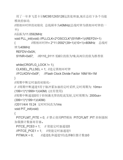
用了一年多飞思卡尔MC9S12XS128这款处理器,现在总结下各个功能模块的驱动.//锁相环时钟的初始化总线频率为40MHz(总线时钟为锁相环时钟的一半)//晶振为11.0592MHzvoid PLL_init(void) //PLLCLK=2*OSCCLK*(SYNR+1)/(REFDV+1) { //锁相环时钟= 2*11.0592*(39+1)/(10+1)=80MHz 总线时钟为40MHzREFDV=0x0A;SYNR=0x67; //0110_0111 低6位的值为19,高两位的值为推荐值while(CRGFLG_LOCK != 1);CLKSEL_PLLSEL = 1; //选定锁相环时钟//FCLKDIV=0x0F; //Flash Clock Divide Factor 16M/16=1M}//周期中断定时器的初始化-// //周期中断通道1用于脉冲累加器的定时采样,定时周期为: 10ms= (199+1)*(1999+1)/(40M) (没有使用)//周期中断通道0用于控制激光管的轮流发射,定时周期为: 2000us= (399+1)*(199+1)/(40M)//2011/4/4 15:24 定时时间改为1msvoid PIT_init(void){PITCFLMT_PITE = 0; // 禁止使用PIT模块 PITCFLMT :PIT 控制强制加载微计数器寄存器。
PITCE_PCE0 = 1; // 使能定时器通道0//PITCE_PCE1 = 1; //使能定时器通道1PITMUX = 0; //通道0,和通道1均选择8位微计数器0//修改时间只需要改下面四行PITMTLD0 = 199; //向8位微计数器中加载的值PITLD0 = 199; //向16位计数器中加载的值//PITMTLD1 = 39; //向8位微计数器中加载的值 8位,最大值不要超过255//PITLD1 = 1999; //向16位计数器中加载的值PITINTE |= 0x01; //使能定时器通道0的中断PITCFLMT_PITE = 1;//使能PIT模块}//脉冲累加器的初始化, PT7口外接光电编码器//最新修改: 2011/3/25 16:53void PT7_PulAcc_Init(void){DDRT &= 0x77;//设置PT7,PT3口为输入(硬件上PT7,PT3通过跳线联到了一块)PERT |= 0x80; //使能通道7的上拉电阻PPST &= 0x7f; //电阻设为上拉电阻TCTL4 &= 0x3f; //禁止PT3的输入捕捉功能PACTL = 0x50; //启动脉冲累加计数器,上升沿触发,禁止触发中断和溢出中断,主定时器禁止}//通道1用于控制舵机1 PWM 高电平有效,//通道3用于控制电机1 PWM 低电平有效,这与前两代车高电平有效有区别!!!!!//通道7用于给上排激光管提供PWM信号 PWM高电平有效!!!!!//通道6用于给下排激光管提供PWM信号 PWM高电平有效!!!!!// 2011-03-17 7:56 增加了A端口的使用新增通道6//2011-6-9 23:03 //增加了通道4,5的联合使用,用于控制下排方向舵机 void PWM_init(void){PWME = 0x00;//PWM禁止PWMPRCLK = 0x03; // ClockA=40M/8=5M, Clock B = 40M/1=40M PWMSCLB = 10; // Clock SB= 40/2*10= 2MHz(供电机)PWMSCLA = 5; // SA = Clock A/2*5 = 5M/10 = 500K = SA 用于控制舵机PWMPOL = 0xe2; //1110_0010通道7,通道6与通道1、通道5先输出高电平然后输出低电平,POLx=1先输出高电平后输出低电平; PPOLx=0先输出低电平)PWMCAE = 0x00; // 左对齐输出(CAEx=0为左对齐,反之为中心对齐)//PWMCLK = 0010_1010 (0 1 4 5位控制SA_1;或A_0; 2 3 6 7位控制SB_1 或B_0)//为PWM通道1选择时钟 SA(500KHz),//为PWM通道5选择时钟 SA(500KHz),//为通道3选择时钟 SB(10MHz)//为通道7选择时钟B(40MHz)//为通道6选择时钟B(40MHz)PWMCLK = 0x2A; //0010_1010PWMCTL = 0x70; //0111_0000 CON45=1,把通道4,5联合使用。
飞思卡尔MC9S12单片机实验程序
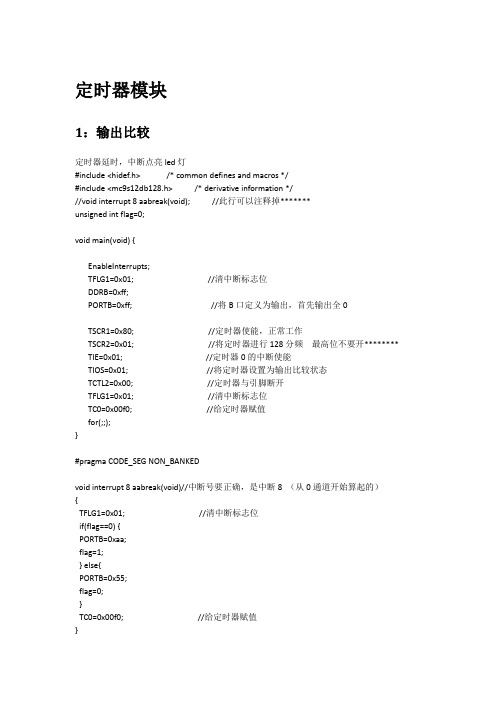
PORTB=0xff; //led灯全暗
TIOS=0x00; //设置定时器通道0为输入捕捉
TSCR1=0x80; //定时器使能
TSCR2=0x01; //设置自由计数器2分频,且禁止定时器溢出中断
TCTL4=0x02; //捕捉器仅下降沿捕捉
TIE=0x01; //允许定时器通道0的中断
}
}
void main(void) {
DDRB=0xff;
PORTB=0x00;
for(;;)
{
fun();
}
}
SCI
#include <hidef.h>
#include <mc9s12db128.h>
#pragma LINK_INFO DERIVATIVE "mc9s12db128b"
unsigned char pp=0xf0; //欲发送的数字
/*********串口初始化*********/
void init() {
DDRB=0xff;
PORTB=0xff; //开始led灯暗,即数据尚未接收
SCI0BD=52; //初始化波特率为9600
SCI0CR1=0x00; //八位无奇偶校验模式
SCI0CR2=0x2c; //接收中断允许
}
/**************写数据***********/
void interrupt 20 funck() {
unsigned char k;
k=read();
PORTB=~k;
}
SPI
不会,以后补充。
LED
#include <hidef.h> /* common defines and macros */
飞思卡尔单片机mc9s12dg128的pwm参考程序

飞思卡尔单片机m c9s12d g128的p w m参考程序(总3页)--本页仅作为文档封面,使用时请直接删除即可----内页可以根据需求调整合适字体及大小--飞思卡尔单片机mc9s12dg128的pwm参考程序大学生参考网发表时间:10月13日 17:44 提交:demon#include <> /* common defines and macros */#include <> /* derivative information*/#pragma LINK_INFO DERIVATIVE "mc9s12dg128b"/***********************************************************pwm初始化函数北华大学王盼宝 by demon 2007-5-12*********************************************************/voidpwm_initial()//pwm初始化函数{ PWME=0x22;//通道01,45使能 PWMPOL=0x22;//通道01,45输出波形开始极性为1 PWMCTL=0x50;//通道01,45级联 PWMCLK=0x02;//通道01选择SA为时钟源 PWMSCLA=0X04;//通道01时钟SA为3MHz(24/(2*4))PWMPER01=60000;//设定通道01输出频率(50Hz)PWMPER45=12000;//设定通道45输出频率(2KHz)}/***********************************************************pwm输出函数 by demon 2007-5-12*程序描述;由输入参数向舵机和电机输出相应pwm*参数:舵机方向:3300-5700 速度:0-12000*********************************************************/void pwm(int speed,int direction)//pwm{pwm_initial();if(direction<3300)direction=3300; if(direction>5700) direction=5700; PWMDTY01=direction;if(speed>12000) speed=12000;PWMDTY45=speed; }飞思卡尔单片机mc9s12dg128的io口初始化参考程序大学生参考网发表时间:10月13日 17:47 提交:demon#include <> /* common defines and macros */#include <> /* derivative information*/#pragma LINK_INFO DERIVATIVE "mc9s12dg128b"北华大学王盼宝void main(){ DDRA=0x00; DDRB=0xFF;PUCR=0x02; while(1){ PORTB=PORTA; } EnableInterrupts;for(;;) {} /* wait forever *//* please make sure that you never leave this function */}飞思卡尔单片机mc9s12dg128的ad初始化参考程序void AD(void) { word t0=0;word t1=0;word t2=0;word t3=0;word t4=0;word t5=0;word t6=0;word t7=0;while(ATD0STAT0_SCF) { t0=ATD0DR0; ad00= (byte)(t0>>8);//高8位移到低8位且高8位为0 t1=ATD0DR1; ad01=(byte)(t1>>8); t2=ATD0DR2; ad02=(byte)(t2>>8); t3=ATD0DR3; ad03=(byte)(t3>>8); t4=ATD0DR4; ad04=(byte)(t4>>8); t5=ATD0DR5; ad05=(byte)(t5>>8); t6=ATD0DR6; ad06=(byte)(t6>>8); t7=ATD0DR7; ad07= (byte)(t7>>8); }。
FreeScale HCS12系列单片机教程(dg128)

HCS12微控制器系列教程---第一讲:PWM 模块介绍该教程以MC9S12DG128单片机为核心进行讲解,全面阐释该16位单片机资源。
本文为第一讲,开始介绍S12 MCU的PWM模块。
PWM 调制波有8 个输出通道,每一个输出通道都可以独立的进行输出。
每一个输出通道都有一个精确的计数器(计算脉冲的个数),一个周期控制寄存器和两个可供选择的时钟源。
每一个PWM 输出通道都能调制出占空比从0—100% 变化的波形。
PWM 的主要特点有:1、它有8 个独立的输出通道,并且通过编程可控制其输出波形的周期。
2、每一个输出通道都有一个精确的计数器。
3、每一个通道的PWM 输出使能都可以由编程来控制。
4、PWM输出波形的翻转控制可以通过编程来实现。
5、周期和脉宽可以被双缓冲。
当通道关闭或PWM计数器为0时,改变周期和脉宽才起作用。
6、8 字节或16 字节的通道协议。
7、有4 个时钟源可供选择(A、SA、B、SB),他们提供了一个宽范围的时钟频率。
8、通过编程可以实现希望的时钟周期。
9、具有遇到紧急情况关闭程序的功能。
10、每一个通道都可以通过编程实现左对齐输出还是居中对齐输出。
HCS12微控制器系列教程---第二讲:PWM 寄存器简介1、PWM启动寄存器PWMEPWME 寄存器每一位如图1所示:复位默认值:0000 0000B图1 PWME 寄存器每一个PWM 的输出通道都有一个使能位PWMEx 。
它相当于一个开关,用来启动和关闭相应通道的PWM 波形输出。
当任意的PWMEx 位置1,则相关的PWM输出通道就立刻可用。
用法:PWME7=1 --- 通道7 可对外输出波形PWME7=0 --- 通道7 不能对外输出波形注意:在通道使能后所输出的第一个波形可能是不规则的。
当输出通道工作在串联模式时(PWMCTL寄存器中的CONxx置1),那么)使能相应的16位PWM 输出通道是由PWMEx的高位控制的,例如:设置PWMCTL_CON01 = 1,通道0、1级联,形成一个16位PWM 通道,由通道 1 的使能位控制PWM 的输出。
Freescale_MC9S12XS128程序总结

1.对IO口输入输出操作程序举例:A口接流水灯并实现闪烁void main(void) {while(1){DDRA=0xff;delay(500);PORTA=0xff;delay(500);PORTA=0;}另外,B、E口的IO功能操作也是一样的,因为位数一样寄存器一样,其他口的寄存器就不太一样了!J,P,M,T,S这五个口除具有数据寄存器外,他们都另外多出另一个端口输入寄存器(该寄存器功能我未知)!2.SPI总线接口SPI是一种高速高效的同步串行接口,这种接口主要用于MCU与外部的接口芯片交换数据,只要有SPI口的芯片都可以与单片机相连形成主从机系统进行数据的传递,比如SPI用于移位寄存器74HC164,这是个串入并出的芯片这样可以实现扩展IO口。
还有AD转换芯片AD7793,可以实现数模转换,还有飞思卡尔公司的电源管理芯片MC33389。
因设备有限此功能待以后调试!3.SCI总线接口MC9S12DG128单片机有两个SCI模块,可以选用其中任何一个。
他的使用有8个相应寄存器共设置,其中有波特率设置寄存器SCIBDH,SCIBDL,还有控制寄存器SCICR1,SCICR2,状态寄存器SCISR1,SCISR2,数据寄存器SCIDRH,SCIDRL;简单讲SCI的使用就是寄存器初始化,数据传送方式设置,下面举个初始化使用的简单例子:SCICR2=0x08;//发送使能设置SCIBDH=0x00;//波特率设置为9600SCIBDL=0x9c;就是这样这个是简单实用时的设置,发送函数如下:While(!(SCISR1&0x40))//检测是否发送完毕,一旦发送完毕就进入到死循环里边{}SCIDRL=C;//C代表需要传送的数据4.有关定时器TCNTTCNT是芯片内部的16位主定时器,他不停地对内部时钟信号进行计数,从0x0000直到0xffff,计满后溢出又返回到0x0000,程序随时可以读取,但在普通模式下禁止写入。
基于Freescale9S+12DG128的智能车控制系统设计

传感器模块, 是智能车的 “眼睛” , 可以通过一定的前瞻性, 提前 感知前方的跑道信息, 为智能车的 “大脑” 做出决策提供必要的依据 和充足的反应时间。 电源模块, 是整个智能车的 “力量源泉” , 统提供合适而又稳定 的电源。 电机驱动模块, 驱动直流电机和伺服电机完成智能车的加减速 控制和转向控制。 速度检测模块, 检测反馈智能车后轮的转速, 用于速度的闭环 控制。 辅助调试模块主要用于智能车系统的功能调试、 智能车状态监 控等方面。
3.3 PID 控制
P ID控制策略其结构简单, 稳定性好, 可靠性高, 并且易于实 现。 其缺点在于控制器的参数整 定相当繁琐, 需要很强的工程经 验。 相对于其他的控制方式, 在成 熟性和可操作性上都有着很大的 优势。 所以最后我们选择了P I D 的控制方式。 在电机速度的控制上, 选用 了增量式P ID控制, 使电机能够 根据道路情况快速准确的改变转 速, 实现入弯时减速, 出弯时加 速。 在本方案中, 使用试凑法来确
数控技术
数字技术 与应用
基于 Freescale9S 12DG128 的智能车控制系统设计
秦健强 贾旭 刘凤国 张晓军
(山东交通学院信电学院 山东济南 250023)
摘要: 本智能车控制系统采用飞思卡尔16位单片机MC9S12DG128作为核心控制单元, 自主构思控制方案及系统设计, 主要包括传感器信 号采集处理、 控制算法及执行、 直流电机驱动、 转向舵机控制等。 较好的完成在规定跑道, 特别是弯道、 坡道的竞速要求。 关键词: MC9S12XS128 传感器 闭环反馈控制 速度闭环控制 舵机控制 中图分类号:TP242 文献标识码: A 文章编号: 1007-9416(2012)09-0006-03
3.5 系统软件流程图
飞思卡尔单片机 DG128 Timer模块介绍
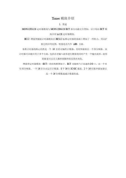
Timer模块介绍1、简述MC9S12XS128定时器模块与MC9S12DG128 ECT部分功能完全类似,以下均以ECT模块介绍xs128定时器模块。
HC12 增强型捕捉计时器模块在HCS12标准定时器的基础上增加了一些特点,用以扩展它的应用范围,特别是在汽车ABS 方面。
基准计时器的核心仍然是一个16 位的可编程计数器,其时钟源来自一个预分频器。
该计时器可以被应用于多个方面,包括在对输入波形进行测量的同时产生一个输出波形。
波形的脉宽可以在几微秒到数秒的范围内变化。
增强型定时器模块(ECT)的结构框图如下,ECT功能相当于高速的I/O口,由一个4位预分频器、一个16位自由运行计数器,8个16位IC/OC通道,2个16位脉冲累加器以及一个16位模数递减计数器组成。
ECT实际上是一个16位的可编程计数器,它的基本时钟频率可以通过预分频器设置,用于产生波形输出,测量输入波形,统计脉冲个数,可以作为定时中断功能和独立时钟基准。
2、运行模式停止:由于时钟停止,计时器和计数器均关闭。
冻结:计时器和计数器均保持运行,直到T SCR($06)的T SFRZ 位被置1。
等待:计数器保持运行,直到T SCR($06)的T SW AI 位被置1。
正常:计时器和计数器均保持运行,直到T SCR($06)的T EN 位和M CCTL($26)的M CEN 位被分别清0。
IC 通道组IC 通道组由四个标准的缓冲通道IC0-IC3 和四个非缓冲通道IC4-IC7 组成,两部分的基本功能都是捕捉外部事件发生的时刻,但是缓冲通道除了IC/OC 寄存器TCn 外,还设有保持寄存器TCnH,此外还在入口设置了延迟计数器,用来提高抗干扰能力。
非缓冲通道没有保持寄存器,入口也没有延迟计数器,但每个通道入口设置了一个 2 输入端的多路器,事件触发信号可以是来自本通道的输入引脚PORTn,也可以是来自其关联通道PORT(n-4)的延迟计数器输出,使用更加灵活。
飞思卡尔智能车-XS128芯片中文资料
第一讲:HCS12原理及应用--PWM模块介绍时间:2009-11-25 22:51来源:电子设计吧作者:dzsj8 点击:996次该教程以MC9S12DG128单片机为核心进行讲解,全面阐释该16位单片机资源。
本文为第一讲,开始介绍该MCU的PWM模块。
PWM 调制波有8个输出通道,每一个输出通道都可以独立的进行输出。
每一个输出通道都有一个精确的计数器(计算脉冲的个数),一个周期控制寄存器和两个可供选择的时钟源。
每一个P WM 输出通道都能调制出占空比从0—100% 变化的波形。
PWM 的主要特点有:1、它有8个独立的输出通道,并且通过编程可控制其输出波形的周期。
2、每一个输出通道都有一个精确的计数器。
3、每一个通道的P WM 输出使能都可以由编程来控制。
4、PWM 输出波形的翻转控制可以通过编程来实现。
5、周期和脉宽可以被双缓冲。
当通道关闭或PWM 计数器为0时,改变周期和脉宽才起作用。
6、8 字节或16 字节的通道协议。
7、有4个时钟源可供选择(A、SA、B、SB),他们提供了一个宽范围的时钟频率。
8、通过编程可以实现希望的时钟周期。
9、具有遇到紧急情况关闭程序的功能。
10、每一个通道都可以通过编程实现左对齐输出还是居中对齐输出。
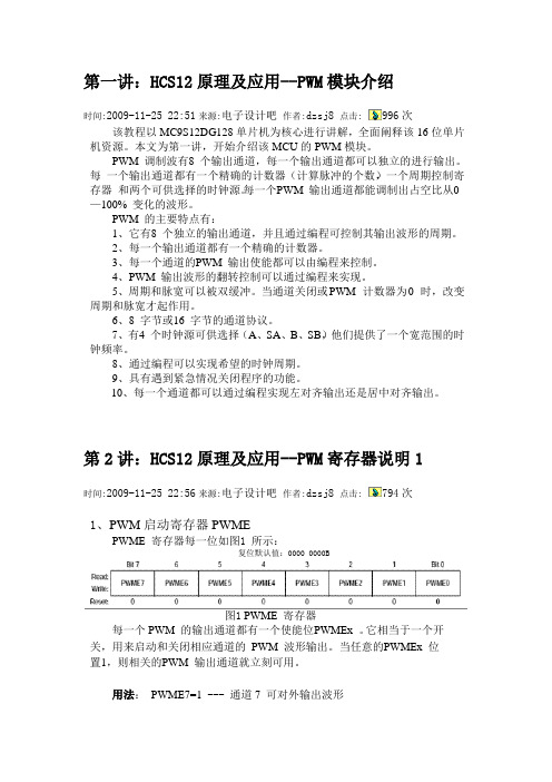
第2讲:HCS12原理及应用--PWM寄存器说明1时间:2009-11-25 22:56来源:电子设计吧作者:dzsj8 点击:794次1、PWM启动寄存器PWMEPWME 寄存器每一位如图1所示:复位默认值:0000 0000B图1 PWME 寄存器每一个PWM 的输出通道都有一个使能位P WMEx 。
它相当于一个开关,用来启动和关闭相应通道的PWM 波形输出。
当任意的P WMEx 位置1,则相关的P WM 输出通道就立刻可用。
用法:PWME7=1 --- 通道7 可对外输出波形PWME7=0 --- 通道7 不能对外输出波形注意:在通道使能后所输出的第一个波形可能是不规则的。
Freescale 9S12 系列单片机应用笔记(ECT 模块) 4

Freescale 9S12 系列单片机应用笔记(ECT 模块)4实验4:定时器溢出翻转功能所谓定时器溢出翻转就是在TCNT溢出时将某个通道的输出管腿PTx电平翻转一下。
这个功能很实用,可以实现PWM功能。
首先,还是要介绍个相关的寄存器TTOV。
TTOV寄存器(TimerToggleOnOverflowRegister1)定时器溢出触发寄存器TTOV很简单,8位寄存器每一位对应一个输出比较通道,相应位置1后表示允许根据溢出特性翻转对应输出比较引脚。
置0则禁止这一功能。
图13TTOV寄存器有这些知识就足够了,下面开始我们的实验。
这个实验的输出和上一个实验相同,将在PT0管腿上输出一个占空比位1/4的方波,不同的是实现方法。
在TCNT=TC0=49152时将PT0管腿置1,然后在TCNT溢出时翻转PT0。
程序片段如下。
#include#include/*commondefinesandmacros*/#include”derivative.h”/*derivative- specificdefinitions*/#include”sci.h”voidECTInit(void){TSCR2_TOI=1;//timeroverflo winterruptenableTIOS_IOS0=1;//channel0asoutputcompareTC0=15000;TCTL2_OL0 =1;TCTL2_OM0=0;//使channel0输出高电平TIOS_IOS7=1;//channel7asoutputcompareTC7=20000;TCTL1_OL7=1;TCTL1_OM 7=0;//使channel0输出高电平TSCR2_TCRE=1;//TCNToverflowwhenTCNT=TC7=20000TTOV_TOV0=1;//TCNT计数溢出时翻转PT0TSCR1_TEN=1;//timerenable}voidmain(void){SCIInit(); SCISetBaudRate(SCI0,9600,8192000L);ECTInit();DDRM_DDRM0=1;EnableInterr upts;for(;;){_FEED_COP();/*feedsthedog*/}/*loopforever*/}。
freescale单片机硬件设计pwm

? 周期计算公式:
? 左对齐方式时 输出周期=通道时钟周期* (PWMPERx+1);
? 中心对齐方式时 输出周期=通道时钟周 期*(PWMPERx*2)。
? 占空比计算公式: ? 极性设置寄存器为0时 占空比
=[(PWMPERx-
PWMDTYx)/PWMPERx]*100%;
? 极性设置寄存器为1时 占空比 =(PWMDTYx/PWMPERx)*100%。
? FRZ0,FRZ1是背景调试冻结控制位。此位 控制程序运行到断点时AD转换是否进行。 此位置一般是设定为继续运行,即不用修 改。
freescale 单片机MC9S12G128应用程序(PWM,Timer,ADC……)

PWM应用程序/*程序实现功能:PP1口输出PWM方波程序说明:通过改变duty和period ,从而控制PWM周期和占空比duty cycle=duty/periodPWM frequency=1M/(2*period)(Fbus=24M,scla=24)*/#include <hidef.h> /* common defines and macros */#include "derivative.h" /* derivative-specific definitions */void SetBusClock_24MHZ(void);void PWMDisable(byte channel);void PWMEnable(byte channel);void PWMSinglePortSetting(byte channel ,byte period ,byte duty) ;void PWMsinglePortInitial(byte channel, byte clkab,byte clock, byte polarity,byte align) ; void Service_WD(void);void PWMGeneralInitial(byte prclk,byte scla,byte sclb,byte ctl);void PWMConcatenateSetting(byte channel,word period,word duty);void main(void){/* put your own code here *///总线时钟频率设置:24MSetBusClock_24MHZ();//对预分频时钟,分频时钟A,分频时钟B和控制寄存器的配置//0分频01级联PWMGeneralInitial(0,24,0,0x10);//PWM端口寄存器的配置// 1通道SA时钟起始高电平左对齐PWMsinglePortInitial(1,0,1,1,0);//PWM级联输出配置//50HZ 占空比12.5%PWMConcatenateSetting(1,10000,250);//EnableInterrupts;for(;;) {_FEED_COP(); /* feeds the dog */} /* loop forever *//* please make sure that you never leave main */}//*********************************************//函数名:PWMEnable//函数功能:PWM单个端口使能//函数参数:一个byte 类型channel 代表PWM通道号// 返回值:无//********************************************void PWMEnable(byte channel){if(channel>7) channel=7;PWME|=(1<<channel); //选择使能位}//**********************************************//函数名称:PWMDisable//函数功能:PWM单个端口禁止//函数参数:一个byte类型channel 代表PWM通道号//返回值:无//***********************************************void PWMDisable(byte channel){if(channel>7) channel=7;PWME&=~(1<<channel); //选择禁止位}//函数功能:启动看门狗void Service_WD(void){CPMUARMCOP=0x55;CPMUARMCOP=0xAA;}//函数功能:总线时钟设置void SetBusClock_24MHZ(void){CPMUOSC_OSCE=1; //enable osc/*时钟倍频:24MHz BusClock48MHz VCO48MHz PLL*/CPMUSYNR=0x00|0x05; //VCOFRQ[1:0],SYNDIV[5:0]CPMUREFDIV=0x20|0x03;//REFFRQ[1:0],REFDIV[3:0]CPMUPOSTDIV=0x00; //POSTDIV=0;while(!CPMUFLG_LOCK)//等待VCO稳定Service_WD(); //看门狗CPMUCLKS_PLLSEL=1;}//*********************************************//函数名称:PWMSinglePortSetting//函数功能:实现PWM周期寄存器和占空比寄存器通道的单独输出//函数参数:3个byte类型//参数1:channel代表了当前配置的PWM通道//参数2:period 周期配置参数/*Left aligned output (CAEx = 0) PWMx Period = Channel Clock Period * PWMPERxCenter Aligned Output (CAEx = 1) PWMx Period = Channel Clock Period * (2 * PWMPERx)*///参数3:duty 占空比配置参数/*Polarity = 0 (PPOL x =0) Duty Cycle = [(PWMPERx-PWMDTYx)/PWMPERx] * 100%Polarity = 1 (PPOLx = 1) Duty Cycle = [PWMDTYx / PWMPERx] * 100%*///返回值:无//**********************************************void PWMSinglePortSetting(byte channel ,byte period ,byte duty){if(channel>7) channel=7;PWMDisable(channel); //禁止该通道switch(channel){case 0:PWMPER0=period; //设置周期寄存器PWMDTY0=duty; //设置占空比寄存器break;case 1:PWMPER1=period; //设置周期寄存器PWMDTY1=duty; //设置占空比寄存器case 2:PWMPER2=period; //设置周期寄存器PWMDTY2=duty; //设置占空比寄存器break;case 3:PWMPER3=period; //设置周期寄存器PWMDTY3=duty; //设置占空比寄存器break;case 4:PWMPER4=period; //设置周期寄存器PWMDTY4=duty; //设置占空比寄存器break;case 5:PWMPER5=period; //设置周期寄存器PWMDTY5=duty; //设置占空比寄存器break;case 6:PWMPER6=period; //设置周期寄存器PWMDTY6=duty; //设置占空比寄存器break;case 7:PWMPER7=period; //设置周期寄存器PWMDTY7=duty; //设置占空比寄存器break;default:break;}PWMEnable(channel);}//*********************************************//函数名:PWMSinglePortInitial//函数功能:PWM端口寄存器的配置//函数参数:5个byte类型//参数1:channel 代表了当前配置的PWM通道//参数2:clkab 参数2,3决定了时钟源的选择//参数3: clock/*PWM Channel 0,1,4,5PCLKAB[0,1,4,5] PCLK[0,1,4,5] Clock Source Selection0 0 Clock A0 1 Clock SA1 0 Clock B1 1 Clock SBPWM Channel 2,3,6,7PCLKAB[2,3,6,7] PCLK[2,3,6,7] Clock Source Selection0 0 Clock B0 1 Clock SB1 0 Clock A1 1 Clock SA*///参数4:polarity PWM极性选择// 0 开始为低电平,周期计数开始为高电平// 1 开始为高电平,周期计数开始为低电平//参数5:align PWM对齐方式选择// 0 输出左对齐// 1 输出中心对齐//返回值:无//**********************************************void PWMsinglePortInitial(byte channel, byte clkab,byte clock, byte polarity,byte align) {if(channel>7) channel=7;//禁止该通道PWMDisable(channel);// PWM 时钟A/B 选择if(clkab==0) PWMCLKAB&=~(1<<channel);else PWMCLKAB|=(1<<channel);// PWM 时钟选择寄存器设置if(clock==0) PWMCLK&=~(1<<channel);else PWMCLK|=(1<<channel);//PWM 极性选择设置if(polarity==0) PWMPOL&=~(1<<channel) ;else PWMPOL|=(1<<channel);//PWM 对齐方式设置if(align==0) PWMCAE&=~(1<<channel);else PWMCAE|=(1<<channel);}//**********************************************************//函数名:PWMGeneralInitial//函数功能:对预分频时钟,分频时钟A,分频时钟B和控制寄存器的配置//函数参数:4个byte类型//参数1 prclk/*Clock A or Clock B Prescaler SelectsPCKA/B2 PCKA/B1 PCKA/B0 Value of Clock A/B0 0 0 Bus clock0 0 1 Bus clock / 20 1 0 Bus clock / 40 1 1 Bus clock / 81 0 0 Bus clock / 161 0 1 Bus clock / 321 1 0 Bus clock / 641 1 1 Bus clock / 128*///参数2:scla// Clock SA = Clock A / (2 * PWMSCLA)//参数3:sclb// Clock SB = Clock B / (2 * PWMSCLB)//参数4:ctl/*control[CON67,CON45,CON23,CON01,PSWAI,PFRZ]PWM级联控制寄存器CON67,CON45,CON23,CON010 单独一个通道1 两个通道级联PSWAI 0 等待模式禁止时钟输入1 等待模式允许时钟输入PFRZ 0 冻结模式允许PWM时钟输入1 冻结模式禁止PWM时钟输入//返回值:无*///**************************************************************void PWMGeneralInitial(byte prclk,byte scla,byte sclb,byte ctl){//禁止所有的PWM通道PWME=0x00;//设置预分频参数PWMPRCLK=prclk;//设置A分频参数PWMSCLA=scla;//设置B分频参数PWMSCLB=sclb;//级联配置PWMCTL=ctl;}//***********************************************************//函数名称:PWMConcatenateSetting//函数功能:PWM级联输出配置//函数参数:1个byte类型,2个word类型//参数1:channel代表了当前配置的PWM通道//参数2:period 周期配置参数/*Left aligned output (CAEx = 0) PWMx Period = Channel Clock Period * PWMPERxCenter Aligned Output (CAEx = 1) PWMx Period = Channel Clock Period * (2 * PWMPERx)*///参数3:duty 占空比配置参数/*Polarity = 0 (PPOL x =0) Duty Cycle = [(PWMPERx-PWMDTYx)/PWMPERx] * 100%Polarity = 1 (PPOLx = 1) Duty Cycle = [PWMDTYx / PWMPERx] * 100%*///返回值:无//**************************************************************void PWMConcatenateSetting(byte channel,word period,word duty){if(channel>7) channel=7;switch(channel){case 0:case 1:PWMDisable(0); //禁止通道0PWMDisable(1); //禁止通道1PWMPER01=period; //设置周期寄存器PWMDTY01=duty; //设置占空比寄存器PWMEnable(0); //使能通道0;PWMEnable(1); //使能通道1;break;case 2:case 3:PWMDisable(2); //禁止通道2PWMDisable(3); //禁止通道3PWMPER23=period; //设置周期寄存器PWMDTY23=duty; //设置占空比寄存器PWMEnable(2); //使能通道2;PWMEnable(3); //使能通道3;break;case 4:case 5:PWMDisable(4); //禁止通道4PWMDisable(5); //禁止通道5PWMPER45=period; //设置周期寄存器PWMDTY45=duty; //设置占空比寄存器PWMEnable(4); //使能通道4;PWMEnable(5); //使能通道5;break;case 6:case 7:PWMDisable(6); //禁止通道6PWMDisable(7); //禁止通道7PWMPER67=period; //设置周期寄存器PWMDTY67=duty; //设置占空比寄存器PWMEnable(6); //使能通道6;PWMEnable(7); //使能通道7;break;default:break;}}定时器应用程序#include <hidef.h> /* common defines and macros */#include "derivative.h" /* derivative-specific definitions */// 函数声明void OutputCompare_Init(void);;void Service_WD(void);void SetBusClock_24MHz(void);// 全局变量uint Timer7_Cnt=0;void main(void) {/* put your own code here */SetBusClock_24MHz();OutputCompare_Init();EnableInterrupts;for(;;) {_FEED_COP(); /* feeds the dog */} /* loop forever *//* please make sure that you never leave main */}void OutputCompare_Init(void){TSCR1_TEN = 0; /* Disable Timer module before adjusting registers. */ TIOS_IOS7 = 1; /* Set Channel 0 as output compare. */ TCTL1_OM7 = 0; /* Set channel 0 to toggle when a Timer match occurs. */ TCTL1_OL7 = 1; /* Set channel 0 to toggle when a Timer match occurs. */ TC7 = 0x4926; /* Set a value for channel 0 timer compare. */ TIE_C7I = 1; /* Enable channel 0 interrupt, handled by function TIM0ISR. */TSCR1_TSWAI = 1; /* Disables the timer module while in wait mode. */ TSCR1_TSFRZ = 1; /* Disables the timer counter while in freeze mode. */TSCR2_PR = 0x7; /* Set prescaler to divide by 128 */ TSCR2_TCRE = 1;TSCR1_TEN = 1; /* Timer Enable. *///中断周期:0x4926*128/24MHz = 100ms}#pragma CODE_SEG __NEAR_SEG NON_BANKEDvoid interrupt VectorNumber_Vtimch7 TIM7_ISR(void){Timer7_Cnt++;TFLG1 = TFLG1_C7F_MASK; /* Clear channel 0 flag. */}#pragma CODE_SEG DEFAULT// 看门狗void Service_WD(void){CPMUARMCOP = 0x55;CPMUARMCOP = 0xAA;}void SetBusClock_24MHz(void){CPMUOSC_OSCE = 1; /* enable ext osc *//*Initialise the system clock from a 16 MHz Crystal,24 MHz Bus CLK (48 MHz VCO, 48 MHz PLL)*/CPMUSYNR = 0x00 | 0x05; /* VCOFRQ[7:6], SYNDIV[5:0] */ CPMUREFDIV = 0x20 | 0x03; /* REFFRQ[7:6], REFDIV[3:0] */ CPMUPOSTDIV = 0x00; /* POSTDIV = 0 FPLL = FVCO */ while(!CPMUFLG_LOCK); /* wait for VCO to stabilize*/ Service_WD();CPMUCLKS_PLLSEL = 1; /* Switch clk to use PLL */}SCI应用程序#include <hidef.h> /* common defines and macros */#include "derivative.h" /* derivative-specific definitions */// 函数声明void SCI0_Init(void);void SCI0_BR(unsigned long br);void SCI0_SendByte(char ch);void Service_WD(void);void SetBusClock_24MHz(void);// 全局变量char SCI_Flag = 0;char SCI_Rev = 0;void main(void) {/* put your own code here */SetBusClock_24MHz();SCI0_BR(38400);SCI0_Init();EnableInterrupts;SCI0_SendByte(0x01);SCI0_SendByte(0x02);SCI0_SendByte(0x03);for(;;) {_FEED_COP(); /* feeds the dog */if(SCI_Flag==1) {SCI_Flag = 0;SCI0_SendByte(SCI_Rev);}} /* loop forever *//* please make sure that you never leave main */}void Service_WD(void){CPMUARMCOP = 0x55;CPMUARMCOP = 0xAA;}void SetBusClock_24MHz(void){CPMUOSC_OSCE = 1; /* enable ext osc *//*Initialise the system clock from a 16 MHz Crystal,24 MHz Bus CLK (48 MHz VCO, 48 MHz PLL)*/CPMUSYNR = 0x00 | 0x05; /* VCOFRQ[7:6], SYNDIV[5:0] */ CPMUREFDIV = 0x20 | 0x03; /* REFFRQ[7:6], REFDIV[3:0] */ CPMUPOSTDIV = 0x00; /* POSTDIV = 0 FPLL = FVCO */ while(!CPMUFLG_LOCK); /* wait for VCO to stabilize*/Service_WD();CPMUCLKS_PLLSEL = 1; /* Switch clk to use PLL */}//串口初始化void SCI0_Init(void){SCI0CR1 = 0x00; /* 8 Data Bits, 1 Start Bit, 1 Stop Bit, No Parity */SCI0CR2 = 0x2C; /* 使能接收中断;使能Tx,Rx *//* SCIASR1, SCIACR1, SCIACR2, SCISR1, SCISR2, SCIDRH & SCIDRL left at default values */ }//串口波特率设置void SCI0_BR(unsigned long br){uint brPrescaler;brPrescaler = (uint)(24000000 / (16 * br));/* Set the Baud Rate */SCI0BDH = (uchar)((brPrescaler>>8));SCI0BDL = (uchar)(brPrescaler);}//串口发送字节void SCI0_SendByte(char ch){/* check SCI transmit data register is empty */while(SCI0SR1_TDRE == 0);SCI0DRL = ch;}//串口中断#pragma CODE_SEG __NEAR_SEG NON_BANKEDvoid interrupt VectorNumber_Vsci0 SCI0_ISR(void){SCI0CR2_RIE=0;while(SCI0SR1_RDRF == 0);SCI_Rev = SCI0DRL;SCI_Flag = 1;SCI0CR2_RIE = 1;}#pragma CODE_SEG DEFAULTADC应用程序#include <hidef.h> /* common defines and macros */#include "derivative.h" /* derivative-specific definitions */// 函数声明void ADC_Init(void);uint ADC_GetValue(byte ch);void Service_WD(void);void SetBusClock_24MHz(void);void Delay(void);// 全局变量uint AD_Result;uint AD_Result2;void main(void) {/* put your own code here */SetBusClock_24MHz();ADC_Init();EnableInterrupts;for(;;) {_FEED_COP(); /* feeds the dog */AD_Result = ADC_GetValue(7);AD_Result2 = ADC_GetValue(0);} /* loop forever *//* please make sure that you never leave main */// AD初始化void ADC_Init(void){ATDCTL1 = 0x3F; /* 10-Bit resolution ,discharge before sampling. */ATDCTL3 = 0x88; /* Right Justified Data, Single conversion sequence */ATDCTL4 = 0xE1; /* 6 MHz, Notice: 12MHz Max ATD Clock, Fatdlk = FBUS/(2*(PRS+1)) *//* 26 ATD Clock cycles sample time */}// ADC通道采集uint ADC_GetValue(byte ch){ATDCTL5 = 0x0F & ch; /* Start Continuous Conversions on ch */while (!ATDSTAT0_SCF); /* wait for conversion sequence to complete */return ATDDR0;}// 看门狗void Service_WD(void){CPMUARMCOP = 0x55;CPMUARMCOP = 0xAA;}void SetBusClock_24MHz(void){CPMUOSC_OSCE = 1; /* enable ext osc *//*Initialise the system clock from a 16 MHz Crystal,24 MHz Bus CLK (48 MHz VCO, 48 MHz PLL)*/CPMUSYNR = 0x00 | 0x05; /* VCOFRQ[7:6], SYNDIV[5:0] */CPMUREFDIV = 0x20 | 0x03; /* REFFRQ[7:6], REFDIV[3:0] */CPMUPOSTDIV = 0x00; /* POSTDIV = 0 FPLL = FVCO */while(!CPMUFLG_LOCK); /* wait for VCO to stabilize*/ Service_WD();CPMUCLKS_PLLSEL = 1; /* Switch clk to use PLL */ }void Delay(void){uint dummy_ctr;for(dummy_ctr=0; dummy_ctr<0x007f;dummy_ctr++){;}}。
Freescale 9S12 系列单片机应用笔记(ECT 模块) 1
Freescale 9S12 系列单片机应用笔记(ECT 模块)1
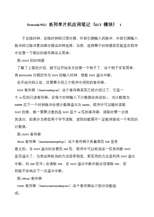
于总线时钟、总线时钟经过预分频、外部引脚输入的脉冲、外部引脚输入脉冲经过脉冲累加器分频这四种选择。
当然,选择哪个时钟源其实就是在程序中设置一下相应的寄存器这么简单。
图2TCNT的时钟源
了解了上面的介绍,就可以开始本文的第一个例子了,这个例子非常简单,将BUSCLOCK分频后作为TCNT的输入时钟,使能TCNT溢出中断。
在开始代码之前,还需要介绍几个程序中用到的寄存器。
TCNT寄存器(TimerCountRegister)这个寄存器其实已经介绍过了,它是一个16位的只读寄存器。
在每个时钟输入下计数值会自动加1,当计数值为
0xFFFF后下一个时钟脉冲会使计数器溢出为0x0000。
程序中可以随时读取TCNT的值,唯一需要注意的是TCNT是个16位的寄存器,读取时要一次将
其读出,如果分为高低两个字节读取,读到的数据不一定能拼接成一个有效的计数值。
图3TCNT寄存器
TFLG2寄存器(MainTimerInterruptFlag2)这个寄存器只有最高位TOF是有意义的。
当TCNT溢出时会置位TOF位,程序中可以轮询这一位来判断TCNT 是否溢出了。
当然这种轮询的方法效率很低,更实用的方法是利用TCNT溢出中断。
向TOF位写1会清除TOF,在TCNT溢出中断中就必须清除TOF,否则就不会响应下一次溢出中断。
图4TFLG2寄存器
TSCR2寄存器(TimerSystemControlRegister2)这个寄存器由三部分功能组成。
- 1、下载文档前请自行甄别文档内容的完整性,平台不提供额外的编辑、内容补充、找答案等附加服务。
- 2、"仅部分预览"的文档,不可在线预览部分如存在完整性等问题,可反馈申请退款(可完整预览的文档不适用该条件!)。
- 3、如文档侵犯您的权益,请联系客服反馈,我们会尽快为您处理(人工客服工作时间:9:00-18:30)。
PWM应用程序/*程序实现功能:PP1口输出PWM方波程序说明:通过改变duty和period ,从而控制PWM周期和占空比duty cycle=duty/periodPWM frequency=1M/(2*period)(Fbus=24M,scla=24)*/#include <hidef.h> /* common defines and macros */#include "derivative.h" /* derivative-specific definitions */void SetBusClock_24MHZ(void);void PWMDisable(byte channel);void PWMEnable(byte channel);void PWMSinglePortSetting(byte channel ,byte period ,byte duty) ;void PWMsinglePortInitial(byte channel, byte clkab,byte clock, byte polarity,byte align) ; void Service_WD(void);void PWMGeneralInitial(byte prclk,byte scla,byte sclb,byte ctl);void PWMConcatenateSetting(byte channel,word period,word duty);void main(void){/* put your own code here *///总线时钟频率设置:24MSetBusClock_24MHZ();//对预分频时钟,分频时钟A,分频时钟B和控制寄存器的配置//0分频01级联PWMGeneralInitial(0,24,0,0x10);//PWM端口寄存器的配置// 1通道SA时钟起始高电平左对齐PWMsinglePortInitial(1,0,1,1,0);//PWM级联输出配置//50HZ 占空比12.5%PWMConcatenateSetting(1,10000,250);//EnableInterrupts;for(;;) {_FEED_COP(); /* feeds the dog */} /* loop forever *//* please make sure that you never leave main */}//*********************************************//函数名:PWMEnable//函数功能:PWM单个端口使能//函数参数:一个byte 类型channel 代表PWM通道号// 返回值:无//********************************************void PWMEnable(byte channel){if(channel>7) channel=7;PWME|=(1<<channel); //选择使能位}//**********************************************//函数名称:PWMDisable//函数功能:PWM单个端口禁止//函数参数:一个byte类型channel 代表PWM通道号//返回值:无//***********************************************void PWMDisable(byte channel){if(channel>7) channel=7;PWME&=~(1<<channel); //选择禁止位}//函数功能:启动看门狗void Service_WD(void){CPMUARMCOP=0x55;CPMUARMCOP=0xAA;}//函数功能:总线时钟设置void SetBusClock_24MHZ(void){CPMUOSC_OSCE=1; //enable osc/*时钟倍频:24MHz BusClock48MHz VCO48MHz PLL*/CPMUSYNR=0x00|0x05; //VCOFRQ[1:0],SYNDIV[5:0]CPMUREFDIV=0x20|0x03;//REFFRQ[1:0],REFDIV[3:0]CPMUPOSTDIV=0x00; //POSTDIV=0;while(!CPMUFLG_LOCK)//等待VCO稳定Service_WD(); //看门狗CPMUCLKS_PLLSEL=1;}//*********************************************//函数名称:PWMSinglePortSetting//函数功能:实现PWM周期寄存器和占空比寄存器通道的单独输出//函数参数:3个byte类型//参数1:channel代表了当前配置的PWM通道//参数2:period 周期配置参数/*Left aligned output (CAEx = 0) PWMx Period = Channel Clock Period * PWMPERxCenter Aligned Output (CAEx = 1) PWMx Period = Channel Clock Period * (2 * PWMPERx)*///参数3:duty 占空比配置参数/*Polarity = 0 (PPOL x =0) Duty Cycle = [(PWMPERx-PWMDTYx)/PWMPERx] * 100%Polarity = 1 (PPOLx = 1) Duty Cycle = [PWMDTYx / PWMPERx] * 100%*///返回值:无//**********************************************void PWMSinglePortSetting(byte channel ,byte period ,byte duty){if(channel>7) channel=7;PWMDisable(channel); //禁止该通道switch(channel){case 0:PWMPER0=period; //设置周期寄存器PWMDTY0=duty; //设置占空比寄存器break;case 1:PWMPER1=period; //设置周期寄存器PWMDTY1=duty; //设置占空比寄存器case 2:PWMPER2=period; //设置周期寄存器PWMDTY2=duty; //设置占空比寄存器break;case 3:PWMPER3=period; //设置周期寄存器PWMDTY3=duty; //设置占空比寄存器break;case 4:PWMPER4=period; //设置周期寄存器PWMDTY4=duty; //设置占空比寄存器break;case 5:PWMPER5=period; //设置周期寄存器PWMDTY5=duty; //设置占空比寄存器break;case 6:PWMPER6=period; //设置周期寄存器PWMDTY6=duty; //设置占空比寄存器break;case 7:PWMPER7=period; //设置周期寄存器PWMDTY7=duty; //设置占空比寄存器break;default:break;}PWMEnable(channel);}//*********************************************//函数名:PWMSinglePortInitial//函数功能:PWM端口寄存器的配置//函数参数:5个byte类型//参数1:channel 代表了当前配置的PWM通道//参数2:clkab 参数2,3决定了时钟源的选择//参数3: clock/*PWM Channel 0,1,4,5PCLKAB[0,1,4,5] PCLK[0,1,4,5] Clock Source Selection0 0 Clock A0 1 Clock SA1 0 Clock B1 1 Clock SBPWM Channel 2,3,6,7PCLKAB[2,3,6,7] PCLK[2,3,6,7] Clock Source Selection0 0 Clock B0 1 Clock SB1 0 Clock A1 1 Clock SA*///参数4:polarity PWM极性选择// 0 开始为低电平,周期计数开始为高电平// 1 开始为高电平,周期计数开始为低电平//参数5:align PWM对齐方式选择// 0 输出左对齐// 1 输出中心对齐//返回值:无//**********************************************void PWMsinglePortInitial(byte channel, byte clkab,byte clock, byte polarity,byte align) {if(channel>7) channel=7;//禁止该通道PWMDisable(channel);// PWM 时钟A/B 选择if(clkab==0) PWMCLKAB&=~(1<<channel);else PWMCLKAB|=(1<<channel);// PWM 时钟选择寄存器设置if(clock==0) PWMCLK&=~(1<<channel);else PWMCLK|=(1<<channel);//PWM 极性选择设置if(polarity==0) PWMPOL&=~(1<<channel) ;else PWMPOL|=(1<<channel);//PWM 对齐方式设置if(align==0) PWMCAE&=~(1<<channel);else PWMCAE|=(1<<channel);}//**********************************************************//函数名:PWMGeneralInitial//函数功能:对预分频时钟,分频时钟A,分频时钟B和控制寄存器的配置//函数参数:4个byte类型//参数1 prclk/*Clock A or Clock B Prescaler SelectsPCKA/B2 PCKA/B1 PCKA/B0 Value of Clock A/B0 0 0 Bus clock0 0 1 Bus clock / 20 1 0 Bus clock / 40 1 1 Bus clock / 81 0 0 Bus clock / 161 0 1 Bus clock / 321 1 0 Bus clock / 641 1 1 Bus clock / 128*///参数2:scla// Clock SA = Clock A / (2 * PWMSCLA)//参数3:sclb// Clock SB = Clock B / (2 * PWMSCLB)//参数4:ctl/*control[CON67,CON45,CON23,CON01,PSWAI,PFRZ]PWM级联控制寄存器CON67,CON45,CON23,CON010 单独一个通道1 两个通道级联PSWAI 0 等待模式禁止时钟输入1 等待模式允许时钟输入PFRZ 0 冻结模式允许PWM时钟输入1 冻结模式禁止PWM时钟输入//返回值:无*///**************************************************************void PWMGeneralInitial(byte prclk,byte scla,byte sclb,byte ctl){//禁止所有的PWM通道PWME=0x00;//设置预分频参数PWMPRCLK=prclk;//设置A分频参数PWMSCLA=scla;//设置B分频参数PWMSCLB=sclb;//级联配置PWMCTL=ctl;}//***********************************************************//函数名称:PWMConcatenateSetting//函数功能:PWM级联输出配置//函数参数:1个byte类型,2个word类型//参数1:channel代表了当前配置的PWM通道//参数2:period 周期配置参数/*Left aligned output (CAEx = 0) PWMx Period = Channel Clock Period * PWMPERxCenter Aligned Output (CAEx = 1) PWMx Period = Channel Clock Period * (2 * PWMPERx)*///参数3:duty 占空比配置参数/*Polarity = 0 (PPOL x =0) Duty Cycle = [(PWMPERx-PWMDTYx)/PWMPERx] * 100%Polarity = 1 (PPOLx = 1) Duty Cycle = [PWMDTYx / PWMPERx] * 100%*///返回值:无//**************************************************************void PWMConcatenateSetting(byte channel,word period,word duty){if(channel>7) channel=7;switch(channel){case 0:case 1:PWMDisable(0); //禁止通道0PWMDisable(1); //禁止通道1PWMPER01=period; //设置周期寄存器PWMDTY01=duty; //设置占空比寄存器PWMEnable(0); //使能通道0;PWMEnable(1); //使能通道1;break;case 2:case 3:PWMDisable(2); //禁止通道2PWMDisable(3); //禁止通道3PWMPER23=period; //设置周期寄存器PWMDTY23=duty; //设置占空比寄存器PWMEnable(2); //使能通道2;PWMEnable(3); //使能通道3;break;case 4:case 5:PWMDisable(4); //禁止通道4PWMDisable(5); //禁止通道5PWMPER45=period; //设置周期寄存器PWMDTY45=duty; //设置占空比寄存器PWMEnable(4); //使能通道4;PWMEnable(5); //使能通道5;break;case 6:case 7:PWMDisable(6); //禁止通道6PWMDisable(7); //禁止通道7PWMPER67=period; //设置周期寄存器PWMDTY67=duty; //设置占空比寄存器PWMEnable(6); //使能通道6;PWMEnable(7); //使能通道7;break;default:break;}}定时器应用程序#include <hidef.h> /* common defines and macros */#include "derivative.h" /* derivative-specific definitions */// 函数声明void OutputCompare_Init(void);;void Service_WD(void);void SetBusClock_24MHz(void);// 全局变量uint Timer7_Cnt=0;void main(void) {/* put your own code here */SetBusClock_24MHz();OutputCompare_Init();EnableInterrupts;for(;;) {_FEED_COP(); /* feeds the dog */} /* loop forever *//* please make sure that you never leave main */}void OutputCompare_Init(void){TSCR1_TEN = 0; /* Disable Timer module before adjusting registers. */ TIOS_IOS7 = 1; /* Set Channel 0 as output compare. */ TCTL1_OM7 = 0; /* Set channel 0 to toggle when a Timer match occurs. */ TCTL1_OL7 = 1; /* Set channel 0 to toggle when a Timer match occurs. */ TC7 = 0x4926; /* Set a value for channel 0 timer compare. */ TIE_C7I = 1; /* Enable channel 0 interrupt, handled by function TIM0ISR. */TSCR1_TSWAI = 1; /* Disables the timer module while in wait mode. */ TSCR1_TSFRZ = 1; /* Disables the timer counter while in freeze mode. */TSCR2_PR = 0x7; /* Set prescaler to divide by 128 */ TSCR2_TCRE = 1;TSCR1_TEN = 1; /* Timer Enable. *///中断周期:0x4926*128/24MHz = 100ms}#pragma CODE_SEG __NEAR_SEG NON_BANKEDvoid interrupt VectorNumber_Vtimch7 TIM7_ISR(void){Timer7_Cnt++;TFLG1 = TFLG1_C7F_MASK; /* Clear channel 0 flag. */}#pragma CODE_SEG DEFAULT// 看门狗void Service_WD(void){CPMUARMCOP = 0x55;CPMUARMCOP = 0xAA;}void SetBusClock_24MHz(void){CPMUOSC_OSCE = 1; /* enable ext osc *//*Initialise the system clock from a 16 MHz Crystal,24 MHz Bus CLK (48 MHz VCO, 48 MHz PLL)*/CPMUSYNR = 0x00 | 0x05; /* VCOFRQ[7:6], SYNDIV[5:0] */ CPMUREFDIV = 0x20 | 0x03; /* REFFRQ[7:6], REFDIV[3:0] */ CPMUPOSTDIV = 0x00; /* POSTDIV = 0 FPLL = FVCO */ while(!CPMUFLG_LOCK); /* wait for VCO to stabilize*/ Service_WD();CPMUCLKS_PLLSEL = 1; /* Switch clk to use PLL */}SCI应用程序#include <hidef.h> /* common defines and macros */#include "derivative.h" /* derivative-specific definitions */// 函数声明void SCI0_Init(void);void SCI0_BR(unsigned long br);void SCI0_SendByte(char ch);void Service_WD(void);void SetBusClock_24MHz(void);// 全局变量char SCI_Flag = 0;char SCI_Rev = 0;void main(void) {/* put your own code here */SetBusClock_24MHz();SCI0_BR(38400);SCI0_Init();EnableInterrupts;SCI0_SendByte(0x01);SCI0_SendByte(0x02);SCI0_SendByte(0x03);for(;;) {_FEED_COP(); /* feeds the dog */if(SCI_Flag==1) {SCI_Flag = 0;SCI0_SendByte(SCI_Rev);}} /* loop forever *//* please make sure that you never leave main */}void Service_WD(void){CPMUARMCOP = 0x55;CPMUARMCOP = 0xAA;}void SetBusClock_24MHz(void){CPMUOSC_OSCE = 1; /* enable ext osc *//*Initialise the system clock from a 16 MHz Crystal,24 MHz Bus CLK (48 MHz VCO, 48 MHz PLL)*/CPMUSYNR = 0x00 | 0x05; /* VCOFRQ[7:6], SYNDIV[5:0] */ CPMUREFDIV = 0x20 | 0x03; /* REFFRQ[7:6], REFDIV[3:0] */ CPMUPOSTDIV = 0x00; /* POSTDIV = 0 FPLL = FVCO */ while(!CPMUFLG_LOCK); /* wait for VCO to stabilize*/Service_WD();CPMUCLKS_PLLSEL = 1; /* Switch clk to use PLL */}//串口初始化void SCI0_Init(void){SCI0CR1 = 0x00; /* 8 Data Bits, 1 Start Bit, 1 Stop Bit, No Parity */SCI0CR2 = 0x2C; /* 使能接收中断;使能Tx,Rx *//* SCIASR1, SCIACR1, SCIACR2, SCISR1, SCISR2, SCIDRH & SCIDRL left at default values */ }//串口波特率设置void SCI0_BR(unsigned long br){uint brPrescaler;brPrescaler = (uint)(24000000 / (16 * br));/* Set the Baud Rate */SCI0BDH = (uchar)((brPrescaler>>8));SCI0BDL = (uchar)(brPrescaler);}//串口发送字节void SCI0_SendByte(char ch){/* check SCI transmit data register is empty */while(SCI0SR1_TDRE == 0);SCI0DRL = ch;}//串口中断#pragma CODE_SEG __NEAR_SEG NON_BANKEDvoid interrupt VectorNumber_Vsci0 SCI0_ISR(void){SCI0CR2_RIE=0;while(SCI0SR1_RDRF == 0);SCI_Rev = SCI0DRL;SCI_Flag = 1;SCI0CR2_RIE = 1;}#pragma CODE_SEG DEFAULTADC应用程序#include <hidef.h> /* common defines and macros */#include "derivative.h" /* derivative-specific definitions */// 函数声明void ADC_Init(void);uint ADC_GetValue(byte ch);void Service_WD(void);void SetBusClock_24MHz(void);void Delay(void);// 全局变量uint AD_Result;uint AD_Result2;void main(void) {/* put your own code here */SetBusClock_24MHz();ADC_Init();EnableInterrupts;for(;;) {_FEED_COP(); /* feeds the dog */AD_Result = ADC_GetValue(7);AD_Result2 = ADC_GetValue(0);} /* loop forever *//* please make sure that you never leave main */// AD初始化void ADC_Init(void){ATDCTL1 = 0x3F; /* 10-Bit resolution ,discharge before sampling. */ATDCTL3 = 0x88; /* Right Justified Data, Single conversion sequence */ATDCTL4 = 0xE1; /* 6 MHz, Notice: 12MHz Max ATD Clock, Fatdlk = FBUS/(2*(PRS+1)) *//* 26 ATD Clock cycles sample time */}// ADC通道采集uint ADC_GetValue(byte ch){ATDCTL5 = 0x0F & ch; /* Start Continuous Conversions on ch */while (!ATDSTAT0_SCF); /* wait for conversion sequence to complete */return ATDDR0;}// 看门狗void Service_WD(void){CPMUARMCOP = 0x55;CPMUARMCOP = 0xAA;}void SetBusClock_24MHz(void){CPMUOSC_OSCE = 1; /* enable ext osc *//*Initialise the system clock from a 16 MHz Crystal,24 MHz Bus CLK (48 MHz VCO, 48 MHz PLL)*/CPMUSYNR = 0x00 | 0x05; /* VCOFRQ[7:6], SYNDIV[5:0] */CPMUREFDIV = 0x20 | 0x03; /* REFFRQ[7:6], REFDIV[3:0] */CPMUPOSTDIV = 0x00; /* POSTDIV = 0 FPLL = FVCO */while(!CPMUFLG_LOCK); /* wait for VCO to stabilize*/ Service_WD();CPMUCLKS_PLLSEL = 1; /* Switch clk to use PLL */ }void Delay(void){uint dummy_ctr;for(dummy_ctr=0; dummy_ctr<0x007f;dummy_ctr++){;}}。
