新型50A和75A_600V压注模封装IPM
600v的半导体放电管

600v的半导体放电管600V的半导体放电管在现代电子技术中扮演着重要的角色。
它是一种能够在高压环境下实现电流控制的器件,具有很多应用领域。
在本文中,我们将探索半导体放电管的工作原理、特性以及应用。
半导体放电管是一种半导体器件,能够在电压超过一定阈值时产生放电现象。
这种器件通常由多个半导体材料层叠而成,其中包含N 型和P型硅等材料。
当电压施加到半导体放电管上时,电子和空穴会在半导体材料中产生,并形成电流。
当电压超过一定阈值时,半导体放电管中的电子和空穴会发生复合,产生能量释放,从而引发放电现象。
半导体放电管的特性使得它在许多领域得到了广泛应用。
首先,它可以用作电子开关,因为它能够在开关状态间快速切换。
这使得它在电力系统中的保护装置中得到了广泛应用,可以有效地防止电流过载和短路等故障。
其次,半导体放电管还可以用于电磁干扰的抑制。
它可以通过在电路中引入一个阻抗,将电磁干扰分散或吸收,从而减少电子设备之间的干扰。
此外,半导体放电管还可以用于光电子器件和激光器等高科技领域。
除了以上应用外,半导体放电管还可以用于电力电子转换器、医疗设备、通信设备等领域。
它的小体积、高效率和可靠性使得它成为了现代电子技术中不可或缺的一部分。
尽管半导体放电管在电子技术中起着重要的作用,但它也存在一些局限性。
首先,它的工作电压范围相对有限,通常在几百伏特至几千伏特之间。
其次,半导体放电管对温度变化非常敏感,过高或过低的温度都可能影响其性能。
此外,半导体放电管还存在寿命限制,长时间使用后可能出现性能下降或故障。
600V的半导体放电管是一种重要的半导体器件,具有广泛的应用领域。
它的工作原理和特性使得它成为现代电子技术中不可或缺的一部分。
然而,它也存在一些局限性,需要在实际应用中加以考虑。
通过深入了解半导体放电管的工作原理和应用,我们可以更好地利用它的优点,为现代电子技术的发展做出贡献。
2N7002A N型增强模MOSFET产品说明书
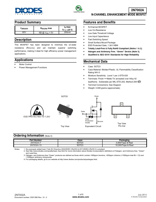
Product SummaryV(BR)DSS R DS(ON) maxI D maxT A = +25°C60V 6Ω @ V GS = 5V 200mA DescriptionThis MOSFET has been designed to minimize the on-state resistance (R DS(ON)) and yet maintain superior switching performance, making it ideal for high efficiency power management applications.Applications∙ MotorControl∙Power Management Functions Features and Benefits∙ N-ChannelMOSFET∙ LowOn-Resistance∙Low Gate Threshold Voltage∙Low Input Capacitance∙Fast Switching Speed∙Small Surface Mount Package∙ESD Protected Gate, 1.2kV HBM∙Totally Lead-Free & Fully RoHS Compliant (Notes 1 & 2)∙Halogen and Antimony Free. “Green” Device (Note 3)∙Qualified to AEC-Q101 Standards for High Reliability Mechanical Data∙ Case:SOT23∙Case Material: Molded Plastic. UL Flammability Classification Rating 94V-0∙Moisture Sensitivity: Level 1 per J-STD-020∙ Terminals:Finish− Matte Tin annealed over Alloy 42leadframe. Solderable per MIL-STD-202, Method 208∙Terminal Connections: See Diagram∙Weight: 0.008 grams (approximate)Ordering Information(Note 4)Part Number Case Packaging2N7002A-7 SOT23 3,000/Tape & Reel2N7002A-13SOT23 10,000/Tape & ReelNotes: 1. No purposely added lead. Fully EU Directive 2002/95/EC (RoHS) & 2011/65/EU (RoHS 2) compliant2. See /quality/lead_free.html for more information about Diodes Incorporated’s definitions of Halogen- and Antimony-free, "Green"and Lead-free.3. Halogen- and Antimony-free "Green” products are defined as those which contain <900ppm bromine, <900ppm chlorine (<1500ppm total Br + Cl) and<1000ppm antimony compounds.4. For packaging details, go to our website at /products/packages.html.SOT23Top View Equivalent CircuitTop ViewPin-Out ESD PROTECTED TO 1.2kVe3Marking InformationDate Code KeyYear 2008 2009 2010 2011 2012 2013 2014 2015 Code V W X Y Z A B CMonth Jan Feb Mar Apr May Jun Jul Aug Sep Oct Nov DecCode 1 2 3 4 5 6 7 8 9 O N DMaximum Ratings (@T A = +25°C, unless otherwise specified.)Characteristic Symbol Value UnitsDrain-Source Voltage V DSS 60 VGate-Source VoltageV GSS ±20 V Continuous Drain Current (Note 5) V GS = 10VSteady State T A = +25°C T A = +85°C T A = +100°C I D180130 115 mAContinuous Drain Current (Note 6) V GS = 10V Steady StateT A = +25°C T A = +85°C T A = +100°CI D 220 160 140mAMaximum Continuous Body Diode Forward Current (Note 6) I S 0.5 A Pulsed Drain Current (10µs pulse, duty cycle = 1%) I DM800 mAThermal Characteristics (@T A = +25°C, unless otherwise specified.)Characteristic Symbol ValueUnitsTotal Power Dissipation (Note 5)P D370 mW (Note 6) 540 Thermal Resistance, Junction to Ambient (Note 5) R θJA348°C/W (Note 6) 241 Thermal Resistance, Junction to Case (Note 6)R θJC 91 Operating and Storage Temperature RangeT J, T STG-55 to +150°CNotes:5. Device mounted on FR-4 PCB, with minimum recommended pad layout6. Device mounted on 1” x 1” FR-4 PCB with high coverage 2oz. Copper, single sided.MN1 = Product Type Marking Code YM = Date Code Marking for SAT (Shanghai Assembly/ Test site) = Date Code Marking for CAT (Chengdu Assembly/ Test site) Y or = Year (ex: A = 2013) M = Month (ex: 9 = September) Shanghai A/T Site Chengdu A/T Site YM Y MN1Y MElectrical Characteristics (@T A = +25°C, unless otherwise specified.)Characteristic SymbolMin Typ Max Unit Test Condition OFF CHARACTERISTICS (Note 7)Drain-Source Breakdown VoltageBV DSS 60 70 − V V GS = 0V, I D= 10µA Zero Gate Voltage Drain Current @ T C = +25°C @ T C = +125°C I DSS − − 1.0 500µAV DS = 60V, V GS = 0VGate-Body LeakageI GSS − − ±10 µA V GS = ±20V, V DS = 0V ON CHARACTERISTICS (Note 7) Gate Threshold VoltageV GS(th)1.2 −2.0 V V DS = V GS , I D= 250µA Static Drain-Source On-Resistance@ T J = +25°C@ T J = +125°CR DS(ON)− 3.53.0 6 5 Ω V GS = 5.0V, I D = 0.115A V GS = 10V, I D =0.115A Forward Transconductanceg FS 80 − − mS V DS = 10V, I D = 0.115ADYNAMIC CHARACTERISTICS (Note 8) Input Capacitance C iss − 23 − pF V DS = 25V, V GS = 0V, f = 1.0MHz Output CapacitanceC oss − 3.4 − pF Reverse Transfer Capacitance C rss − 1.4−pFGate ResistanceR G − 260 400 Ω V DS = 0V, V GS = 0V, f = 1.0MHz SWITCHING CHARACTERISTICS (Note 8) Turn-On Delay Time t D(ON) − 10 − ns V DD = 30V, I D = 0.115A, R L = 150Ω, V GEN = 10V , R GEN = 25Ω Turn-Off Delay Timet D(OFF)−33−nsNotes: 7. Short duration pulse test used to minimize self-heating effect.8. Guaranteed by design. Not subject to product testing.Fig. 2 Typical Transfer CharacteristicsV , GATE SOURCE VOLTAGE (V)GS I , D R A I N C U R R E N T (A )D 0.11Fig. 3 On-Resistance vs. Drain Current & Gate Voltage I , DRAIN-SOURCE CURRENT (A)D R , S T A T I C D R A I N -S O U R CE O N -R E S I S T A N C E ()D S (O N ) 123456789Fig. 5 Gate Threshold Variation vs. Ambient TemperatureT , AMBIENT TEMPERATURE (°C)A V , G A T E T H R E S H O L D V O L T A G E (V )G S (T H )Fig. 6 Typical T otal CapacitanceV , DRAIN-SOURCE VOLTAGE (V)DS C , C A P A C I T A N C E (p F )T 10100Fig. 7 Reverse Drain Current vs. Source-Drain VoltageV , SOURCE-DRAIN VOLTAGE (V)SD I , S O U R C E C U R R E N T (A )SPackage Outline DimensionsPlease see AP02002 at /datasheets/ap02002.pdf for latest version.Suggested Pad LayoutPlease see AP02001 at /datasheets/ap02001.pdf for the latest version.SOT23Dim Min Max Typ A 0.37 0.51 0.40 B 1.20 1.40 1.30 C 2.30 2.50 2.40 D 0.89 1.03 0.915 F 0.45 0.60 0.535 G 1.78 2.05 1.83 H 2.80 3.00 2.90 J 0.0130.10 0.05 K 0.903 1.10 1.00 K1 - - 0.400 L 0.45 0.61 0.55 M 0.0850.18 0.110° 8°- All Dimensions in mmDimensions Value (in mm) Z2.9X 0.8 Y 0.9 C 2.0 E 1.35 X E YCZIMPORTANT NOTICEDIODES INCORPORATED MAKES NO WARRANTY OF ANY KIND, EXPRESS OR IMPLIED, WITH REGARDS TO THIS DOCUMENT, INCLUDING, BUT NOT LIMITED TO, THE IMPLIED WARRANTIES OF MERCHANTABILITY AND FITNESS FOR A PARTICULAR PURPOSE (AND THEIR EQUIVALENTS UNDER THE LAWS OF ANY JURISDICTION).Diodes Incorporated and its subsidiaries reserve the right to make modifications, enhancements, improvements, corrections or other changes without further notice to this document and any product described herein. Diodes Incorporated does not assume any liability arising out of the application or use of this document or any product described herein; neither does Diodes Incorporated convey any license under its patent or trademark rights, nor the rights of others. Any Customer or user of this document or products described herein in such applications shall assume all risks of such use and will agree to hold Diodes Incorporated and all the companies whose products are represented on Diodes Incorporated website, harmless against all damages.Diodes Incorporated does not warrant or accept any liability whatsoever in respect of any products purchased through unauthorized sales channel. Should Customers purchase or use Diodes Incorporated products for any unintended or unauthorized application, Customers shall indemnify and hold Diodes Incorporated and its representatives harmless against all claims, damages, expenses, and attorney fees arising out of, directly or indirectly, any claim of personal injury or death associated with such unintended or unauthorized application.Products described herein may be covered by one or more United States, international or foreign patents pending. Product names and markings noted herein may also be covered by one or more United States, international or foreign trademarks.This document is written in English but may be translated into multiple languages for reference. Only the English version of this document is the final and determinative format released by Diodes Incorporated.LIFE SUPPORTDiodes Incorporated products are specifically not authorized for use as critical components in life support devices or systems without the express written approval of the Chief Executive Officer of Diodes Incorporated. As used herein:A. Life support devices or systems are devices or systems which:1. are intended to implant into the body, or2. support or sustain life and whose failure to perform when properly used in accordance with instructions for use provided in thelabeling can be reasonably expected to result in significant injury to the user.B. A critical component is any component in a life support device or system whose failure to perform can be reasonably expected to cause thefailure of the life support device or to affect its safety or effectiveness.Customers represent that they have all necessary expertise in the safety and regulatory ramifications of their life support devices or systems, and acknowledge and agree that they are solely responsible for all legal, regulatory and safety-related requirements concerning their products and any use of Diodes Incorporated products in such safety-critical, life support devices or systems, notwithstanding any devices- or systems-related information or support that may be provided by Diodes Incorporated. Further, Customers must fully indemnify Diodes Incorporated and its representatives against any damages arising out of the use of Diodes Incorporated products in such safety-critical, life support devices or systems.Copyright © 2013, Diodes Incorporated。
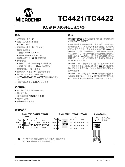
TC4422_中文数据手册
2006 Microchip Technology Inc.
1.0 电气特性
绝对最大值 †
供电电压............................................................... +20V 输入电压 ...........................(VDD + 0.3V) 至 (GND - 5V) 输入电流 (VIN > VDD)...................................... 50 mA 封装功耗 (TA ≤ 70°C)
80 ns 图 4-1
3
mA VIN = 3V
0.2
VIN = 0V
18
V
温度特性
电气规范:除非另外说明,否则所有参数均为 4.5V ≤ VDD ≤ 18V 条件下的值。
参数
符号 最小值 典型值 最大值 单位
条件
温度范围 规定温度范围 (商业级) 规定温度范围 (扩展级) 规定温度范围 (汽车级) 最高结温 储存温度范围 封装热阻 热阻, 5 引脚 TO-220 热阻, 8 引脚 6x5 DFN
2006 Microchip Technology Inc.
DS21420D_CN 第 3 页
TC4421/TC4422
直流特性 (在整个工作温度范围内)
电气规范:除非另外说明,否则温度超出正常工作范围,且 4.5V ≤ VDD ≤ 18V。
参数
符号
最小值 典型值 最大值 单位
条件
输入
逻辑 “1”,高输入电压 逻辑 “0”,低输入电压 输入电流 输出
VIH
2.4
—
VIL
—
概述智能功率模块IGBT—IPM及其应用
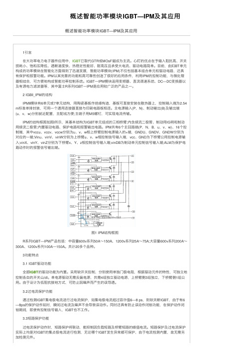
1引⾔ 在⼤功率电⼒电⼦器件应⽤中,IGBT 已取代GTR 或MOsF 龃成为主流。
⼼盯的优点在予输⼊阻抗⾼、开关损耗⼩、饱和压降低、通断速度快、热稳定性能好、耐⾼压且承受⼤电流、驱动电路简单。
⽬前,由妇BT 单元构成的功率模块在智能化⽅⾯得到了迅速发展,智能功率模块(IPM)不仅包括基本组合单元和驱动电路,还具有保护和报警功能。
IPM 以其完善的功能和⾼可靠性创造了很好的应⽤条件,利⽤IPM 的控制功能,与微处理器相结合,可⽅便地构成智能功率控制系统。
IGBT ⼀IPM 模块适⽤变频器、直流调速系统、DC—DC 变换器以及有源电⼒滤波器等,其中富⼠R 系列IGBT ⼀IPM 是应⽤较⼴泛的产品之⼀。
2 IGBll_IPM 的结构 IPM Ⅱ模块有6单元或7单元结构,⽤陶瓷基板作绝缘构造,基板可直接安装在散热器上,控制输⼊端为2.54m 标准单排封装,可⽤⼀个通⽤连接器直接与印刷电路板相连。
主电源输⼊(P ,N)、制动输出(B)及输出端(u ,v ,w)分别就近配置,主配线⽅便;主端⼦⽤M5螺钉,可实现电流传输。
IPM 的结构框图如图l 所⽰,其基本结构为IGBT 单元组成的三相桥臂;内含续流⼆极管、制动⽤IG 明和制动⽤续流⼆极管;内置驱动电路、保护电路和报警输出电路。
IPM 共有6个主回路端(P ,N ,B ,u ,v ,w)、16个控制端,其中vccu 、vccv 、vccw 分别为u 、v 、w 相上桥臂控制电源输⼊的+端,GNDU 、GNDV 、GNDW 分别为对应的⼀端;Vinu 、vinV 、vinW 分别为上桥臂u 、v 、w 相控制信号输⼊端,vcc 、GND 为下桥臂公⽤控制电源输⼊;vinX 、vinY 、vinZ 分别为下桥臂x 、Y 、z 相控制信号输⼊端;vinDB 为制动单元控制信号输⼊端;ALM 为保护电路动作时的报警信号输出端。
图1 IPM 结构框图 R 系列IGBT—IPM 产品包括:中容量600v 系列50A ~150A 、1200v 系列25A ~75A;⼤容量600v 系列200A ~300A 、1200v 系列100A ⼀150A 。
贴片电容封装与耐压值关系
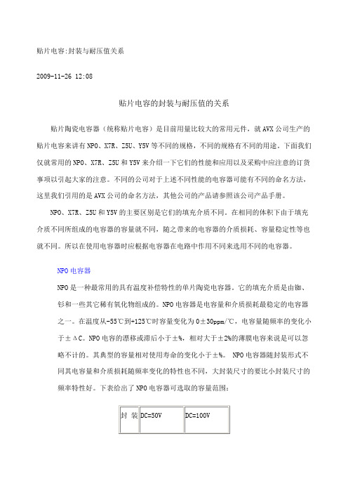
贴片电容:封装与耐压值关系2009-11-26 12:08贴片电容的封装与耐压值的关系贴片陶瓷电容器(统称贴片电容)是目前用量比较大的常用元件,就AVX公司生产的贴片电容来讲有NPO、X7R、Z5U、Y5V等不同的规格,不同的规格有不同的用途。
下面我们仅就常用的NPO、X7R、Z5U和Y5V来介绍一下它们的性能和应用以及采购中应注意的订货事项以引起大家的注意。
不同的公司对于上述不同性能的电容器可能有不同的命名方法,这里我们引用的是AVX公司的命名方法,其他公司的产品请参照该公司产品手册。
NPO、X7R、Z5U和Y5V的主要区别是它们的填充介质不同。
在相同的体积下由于填充介质不同所组成的电容器的容量就不同,随之带来的电容器的介质损耗、容量稳定性等也就不同。
所以在使用电容器时应根据电容器在电路中作用不同来选用不同的电容器。
NPO电容器NPO是一种最常用的具有温度补偿特性的单片陶瓷电容器。
它的填充介质是由铷、钐和一些其它稀有氧化物组成的。
NPO电容器是电容量和介质损耗最稳定的电容器之一。
在温度从-55℃到+125℃时容量变化为0±30ppm/℃,电容量随频率的变化小于±ΔC。
NPO电容的漂移或滞后小于±%,相对大于±2%的薄膜电容来说是可以忽略不计的。
其典型的容量相对使用寿命的变化小于±%。
NPO电容器随封装形式不同其电容量和介质损耗随频率变化的特性也不同,大封装尺寸的要比小封装尺寸的频率特性好。
下表给出了NPO电容器可选取的容量范围:080512061210 560---5600pF 560---2700pF2225 μFμFNPO电容器适合用于振荡器、谐振器的槽路电容,以及高频电路中的耦合电容。
X7R电容器X7R电容器被称为温度稳定型的陶瓷电容器。
当温度在-55℃到+125℃时其容量变化为15%,需要注意的是此时电容器容量变化是非线性的。
X7R电容器的容量在不同的电压和频率条件下是不同的,它也随时间的变化而变化,大约每10年变化1%ΔC,表现为10年变化了约5%。
瞬态抑制二极管5.0SMD型号参数规格书大全

26.0
28.90
31.90
5.0SMDJ 28A-CA 5PFG 5BFG
28.0
31.10
34.40
5.0SMDJ 30A-CA 5PFK
5BFK
30.0
33.30
36.80
5.0SMDJ 33A-CA 5PFM 5BFM
33.0
36.70
40.60
5.0SMDJ 36A-CA 5PFP 5BFP
SURFACE MOUNT TRANSIENT VOLTAGE SUPPRESSOR VOLTAGE-20 TO 170 Volts
5000 Watt Peak Pulse Power
DO-214AB (SMC J-Bend)
Cathode Band
0.126 (3.20) 0.114 (2.90)
Half Value- IPPM 2
50
10/1000µsec.Waveform
as defined by R.E.A.
td
0
0
1.0
2.0 3.0
t - Time(ms)
3.0 4.0
4.0
Fig. 5 - Steady State Power Derating Curve
IFSM
300
Amps
Operating junction and Storage Temperature Range
TJ , TSTG
-55 to + 150
℃
Notes :
1.Non-repetitive current pulse , per Fig. 3 and derated above TA = 25℃ per Fig. 2 .
最全的芯片封装方式_(图文对照)
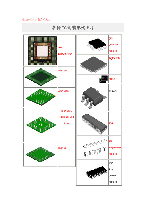
最全的芯片封装方式大全各种IC封装形式图片各种封装缩写说明BGABQFP132BGABGABGABGABGA CLCCCNRPGADIPDIP-tab BGADIPTOFlat PackHSOP28 TOTOJLCC LCCCLCCBGALQFP DIPPGAPLCCPQFPDIP LQFPLQFPPQFPQFPQFPTQFP BGASC-70 5LDIPSIPSOSOHSOJSOJSOPTOSOPSOPCANTOTOTOTO3CANCANCANCANCANTO8TO92CANCANTSOPTSSOP or TSOP BGABGAZIPPCDIP以下封装形式未找到相关图片,仅作简易描述,供参考:DIM单列直插式,塑料例如:MH88500QUIP蜘蛛脚状四排直插式,塑料例如:NEC7810DBGA BGA系列中陶瓷芯片例如:EP20K400FC672-3CBGA BGA系列中金属封装芯片例如: EP20K300EBC652-3 MODULE方形状金属壳双列直插式例如:LH0084RQFP QFP封装系列中,表面带金属散装体例如:EPF10KRC系列DIMM电路正面或背面镶有LCC封装小芯片,陶瓷,双列直插式例如:X28C010DIP-BATTERY电池与微型芯片内封SRAM芯片,塑料双列直插式例如:达拉斯SRAM系列(五)按用途分类集成电路按用途可分为电视机用集成电路。
音响用集成电路、影碟机用集成电路、录像机用集成电路、电脑(微机)用集成电路、电子琴用集成电路、通信用集成电路、照相机用集成电路、遥控集成电路、语言集成电路、报警器用集成电路及各种专用集成电路。
电视机用集成电路包括行、场扫描集成电路、中放集成电路、伴音集成电路、彩色解码集成电路、AV/TV转换集成电路、开关电源集成电路、遥控集成电路、丽音解码集成电路、画中画处理集成电路、微处理器(CPU)集成电路、存储器集成电路等。
音响用集成电路包括AM/FM高中频电路、立体声解码电路、音频前置放大电路、音频运算放大集成电路、音频功率放大集成电路、环绕声处理集成电路、电平驱动集成电路、电子音量控制集成电路、延时混响集成电路、电子开关集成电路等。
IGBT工艺技术

结构技术
•与mos工艺相近 •需要刻深槽 •优化Vce(SAT)& BVces
【设计】
高性能
•芯粒排列紧密可靠 •专为稳定的短路电流设计 的通道
结构技术
•外延电阻率和厚度
高压
•设计厚度和浓度 •可靠的高BV FLR 边界
薄硅片技术
•薄硅片处理 •减薄/粗糙化/损伤层 去除 •高能注入 •低温,激活
IC+分立器件
IC+分立器件+封装
工艺过程参考
列举6种产品的芯粒尺寸和层数
1. 芯片尺寸: 600V IGBT: 3000X3000um, 5600 x 5900um 1200V IGBT: 3000x3000um, 5600 x 5900um 通过设计,可以将芯粒尺寸变小。 2. 产品: 共6项 NPT 1,200V: 15A, 25A NPT 600V: 30A Field Stop 1,200V: 15, 25A Field stop 600V: 50A 3. 层数
IGBT市场目标(2)
市场占有率
大
电磁加热 (1200V)
模块 芯片
点火器 闪光灯
电磁加热 (600V)
马达
焊机
电磁加热 (900V)
逆变器
家用电器
小
低 高
工艺技术
IGBT市场目标(3)
电磁加热市场分析(在中国)
市场趋势
电磁加热情况 在感应加热领域中,中国10 大企业的IGBT消耗量占整体 的50%。 每年以30~40% 的速度增长 1153M 台/广州 竞争者在市场占有率 Infineon(70%) FSC (30%) Infineon (20%)价格高 ﹥1200V/25A(0.80$) FCS,ST 低价策略
超六类双屏蔽网线
超六类双屏蔽网线俗称6A,即万兆系统,超六类双屏蔽网线标准对于测试而言,超六类双屏蔽网线是需要达到500MHZ测试,超六类双屏蔽网线分非屏蔽和屏蔽两种系统。
超六类双屏蔽网线非屏蔽系统,需要增加一个6包1的外来串扰测试。
目前美国的福禄克FLUKE测试达到万兆标准的,应用广泛的为亚太超六类系统,超六类双屏蔽网线非屏蔽的结构,超六类双屏蔽网线目前看,流行的是在六类的基础上,绞距更密,线径更粗,最重要的改变是在PVC外被上的改变,增加塑料棒或者PVC外被做成锯齿状来改善外开串扰测试指标。
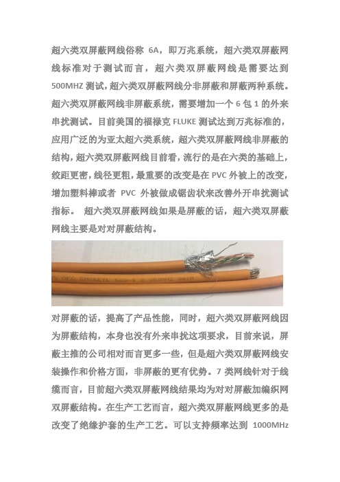
超六类双屏蔽网线如果是屏蔽的话,超六类双屏蔽网线主要是对对屏蔽结构。
对屏蔽的话,提高了产品性能,同时,超六类双屏蔽网线因为屏蔽结构,本身也没有外来串扰这项要求,目前来说,屏蔽主推的公司相对而言更多一些,但是超六类双屏蔽网线安装操作和价格方面,非屏蔽的更有优势。
7类网线针对于线缆而言,目前超六类双屏蔽网线结果均为对对屏蔽加编织网双屏蔽结构。
在生产工艺而言,超六类双屏蔽网线更多的是改变了绝缘护套的生产工艺。
可以支持频率达到1000MHz的传输,10G带宽。
目前能提供的厂家不多,超六类双屏蔽网线基本6A和7类主要用于数据中心,超六类双屏蔽网线----亚太线缆超六类双屏蔽网线----亚太线缆超六类双屏蔽网线----亚太线缆公司简介亚太线缆(AsiaPacificCabl e)是一家致力于:网络综合布线、计算机电缆、屏蔽控制电缆、光纤光缆、电力电缆、通讯产品等研发、生产、销售的科技公司,并提供系统解决方案的公司,是全球知名品牌,总部位于北美,通过其运营子公司在亚太地区从事通讯电缆、电力电缆及漆包线等产品的制造与分销,营运范围主要分布于新加坡、泰国、澳大利亚和中国大陆。
其客户群包括:政府机关、国家电网、系统集成商、通信运营商和跨国企业,服务亚太地区电力基础设施,光电通信设施等为用户提供完善的产品和服务。
凭借着“科技至上、品质至上,团队至上,服务至上”的理念,成为全球电缆通讯行业的领先品牌,并拥有实力雄厚的产品设计研发团队,系统方案解决团队,供应链管理团队以及市场营销团队。
功率模块IGBT、IPM、PIM性能综述说明书

功率模块IGBT、IPM、PIM 的性能及使用时有关问题的综述1 IGBT主要用途IGBT是先进的第三代功率模块,工作频率1-20KHZ,主要应用在变频器的主回路逆变器及一切逆变电路,即DC/AC变换中。
例电动汽车、伺服控制器、UPS、开关电源、斩波电源、无轨电车等。
问世迄今有十年多历史,几乎已替代一切其它功率器件,例SCR、GTO、GTR、MOSFET,双极型达林顿管等,目今功率可高达1MW的低频应用中,单个元件电压可达4.0KV(PT结构)— 6.5KV(NPT结构),电流可达1.5KA,是较为理想的功率模块。
追其原因是第三代IGBT模块,它是电压型控制,输入阻抗大,驱动功率小,控制电路简单,开关损耗小,通断速度快,工作频率高,元件容量大等优点。
实质是个复合功率器件,它集双极型功率晶体管和功率MOSFET的优点于一体化。
又因先进的加工技术使它通态饱和电压低,开关频率高(可达20KHZ),这两点非常显著的特性,最近西门子公司又推出低饱和压降(2.2V)的NPT—IGBT性能更佳,相继东芝、富士、IR、摩托罗拉亦已在开发研制新品种。
IGBT发展趋向是高耐压、大电流、高速度、低压降、高可靠、低成本为目标的,特别是发展高压变频器的应用,简化其主电路,减少使用器件,提高可靠性,降低制造成本,简化调试工作等,都与IGBT有密切的内在联系,所以世界各大器件公司都在奋力研究、开发,予估近2-3年内,会有突破性的进展。
目今已有适用于高压变频器的有电压型HV-IGBT,IGCT,电流型SGCT等。
2 关断浪涌电压在关断瞬时流过IGBT的电流,被切断时而产生的瞬时电压。
它是因带电动机感性负载(L)及电路中漏电感(Lp),其总值L*p = L + Lp则Vp* = Vce + Vp而Vp = L*p di/dt在极端情况下将产生Vp* Vces(额定电压)导致器件的损坏发生,为此要采取尽可能减小电感(L),电路中的漏电感(Lp)—由器件制造结构而定,例合理分布,缩短到线长度,适当加宽减厚等。
爱森摩尔Z5型号超压保护器说明说明书

Eaton 210075Eaton Moeller® series Z5 Overload relay, Ir= 200 - 250 A, 1 N/O, 1 N/C, For use with: DILM250, DILM300AGeneral specificationsEaton Moeller® series Z5 Thermal overload relay2100754015082100759Z5-250/FF250146 mm 167 mm 128 mm 1.727 kgIEC/EN 60947UL Category Control No.: NKCR VDE 0660 CECSA Class No.: 3211-03 ULCSA-C22.2 No. 60947-4-1-14 CSA File No.: 012528 UL 60947-4-1 UL File No.: E29184 IEC/EN 60947-4-1 CSAProduct NameCatalog Number EANModel Code Product Length/Depth Product Height Product Width Product Weight CertificationsReset pushbutton manual/autoTrip-free releaseTest/off buttonPhase-failure sensitivity (according to IEC/EN 60947, VDE 0660 Part 102)-25 °C60 °C25 °C40 °CCLASS 10 ADamp heat, constant, to IEC 60068-2-78Damp heat, cyclic, to IEC 60068-2-30IP00Separate mountingDirect mountingDirect attachment/single positioning200 A250 AIII3Overload relay Z5With terminal cover, Protection against direct contact when actuated from front (EN 50274)4000 V (auxiliary and control circuits)8000 V ACFeatures Ambient operating temperature - minAmbient operating temperature - maxAmbient operating temperature (enclosed) - minAmbient operating temperature (enclosed) - maxClassClimatic proofingDegree of protectionMounting methodOverload release current setting - minOverload release current setting - maxOvervoltage categoryPollution degreeProduct categoryProtectionRated impulse withstand voltage (Uimp)Shock resistance10 g, Mechanical, Sinusoidal, Shock duration 10 ms Branch circuits, (UL/CSA)≤ 0.25 %/K, residual error for T > 40° Continuous 25 mm width, Main connection185 mm²2 x (0.75 - 2.5) mm², Control circuit cables1 x (0.75 - 2.5) mm², Control circuit cables1 x (0.75 - 4) mm², Control circuit cables2 x (0.75 - 4) mm², Control circuit cables2/0 - 500 MCM, Main cables2 x (18 - 14), Control circuit cables185 mm²16 mm (Hexagon head spanner SW)8 mmM10 x 35, Terminal screw, Main connectionsM3.5, Terminal screw, Control circuit cables1 x 6 mm, Terminal screw, Control circuit cables, Standard screwdriver2, Terminal screw, Control circuit cables, Pozidriv screwdriver18 Nm, Main cable connection screw/bolt1.2 Nm, Screw terminals, Control circuit cables6 A 1.5 A 1200 A Class L, max. Fuse, SCCR (UL/CSA) 18 kA, SCCR (UL/CSA)1200 A, max. CB, SCCR (UL/CSA)500 A gG/gL, Fuse, Type “1” coordinationSuitable forTemperature compensationTerminal capacity (busbar)Terminal capacity (flexible with cable lug)Terminal capacity (flexible with ferrule)Terminal capacity (solid)Terminal capacity (solid/stranded AWG)Terminal capacity (stranded with cable lug)Width across flatsStripping length (control circuit cable)Screw sizeScrewdriver sizeTightening torqueConventional thermal current ith of auxiliary contacts (1-pole,open)Rated operational current (Ie) at AC-15, 120 VShort-circuit current rating (basic rating)Short-circuit protection rating1.5 A0.9 A0.4 A0.2 A0.9 A0.75 A1000 V440 V, Between auxiliary contacts and main contacts, According to EN 61140240 V AC, Between auxiliary contacts, According to EN 61140 500 V AC, Between main circuits, According to EN 61140R300, DC operated (UL/CSA)B300 at opposite polarity, AC operated (UL/CSA)B600 at opposite polarity, AC operated (UL/CSA)600 VAC600 VAC 500 A gG/gL, Fuse, Type “2” coordinationMax. 6 A gG/gL, fuse, Without welding, Auxiliary and control circuits111143.5 W0 W14.5 W250 A0 WMeets the product standard's requirements.Meets the product standard's requirements.Meets the product standard's requirements.Meets the product standard's requirements.Rated operational current (Ie) at AC-15, 220 V, 230 V, 240 V Rated operational current (Ie) at AC-15, 380 V, 400 V, 415 V Rated operational current (Ie) at DC-13, 110 VRated operational current (Ie) at DC-13, 220 V, 230 V Rated operational current (Ie) at DC-13, 24 VRated operational current (Ie) at DC-13, 60 VRated operational voltage (Ue) - maxSafe isolationSwitching capacity (auxiliary contacts, pilot duty) Voltage rating - maxVoltage rating - max Number of auxiliary contacts (change-over contacts)Number of auxiliary contacts (normally closed contacts) Number of auxiliary contacts (normally open contacts) Number of contacts (normally closed contacts)Number of contacts (normally open contacts)Equipment heat dissipation, current-dependent PvidHeat dissipation capacity PdissHeat dissipation per pole, current-dependent PvidRated operational current for specified heat dissipation (In) Static heat dissipation, non-current-dependent Pvs10.2.2 Corrosion resistance10.2.3.1 Verification of thermal stability of enclosures10.2.3.2 Verification of resistance of insulating materials to normal heat10.2.3.3 Resist. of insul. mat. to abnormal heat/fire by internal elect. effectsMeets the product standard's requirements.Does not apply, since the entire switchgear needs to be evaluated.Does not apply, since the entire switchgear needs to be evaluated.Meets the product standard's requirements.Does not apply, since the entire switchgear needs to be evaluated.Meets the product standard's requirements.Does not apply, since the entire switchgear needs to be evaluated.Does not apply, since the entire switchgear needs to be evaluated.Is the panel builder's responsibility.Is the panel builder's responsibility.Is the panel builder's responsibility.Is the panel builder's responsibility.Is the panel builder's responsibility.The panel builder is responsible for the temperature rise calculation. Eaton will provide heat dissipation data for the devices.Is the panel builder's responsibility. The specifications for the switchgear must be observed.Product Range Catalog Switching and protecting motorseaton-tripping-devices-z5-overload-relay-characteristic-curve-003.eps eaton-tripping-z5-overload-relay-characteristic-curve.epsDA-DC-00004856.pdfDA-DC-00004846.pdfeaton-tripping-devices-overload-relay-z5-overload-relay-dimensions-002.epseaton-tripping-devices-overload-relay-z5-overload-relay-3d-drawing.epsDA-CE-ETN.Z5-250_FF250IL03407006ZIL026005ZUIL03407081ZDA-MN-h1476dgbDA-CS-z5_ff250DA-CD-z5_ff250eaton-general-release-zeb-overload-relay-wiring-diagram.epseaton-tripping-devices-overload-relay-zeb-overload-relay-wiring-diagram.eps10.2.4 Resistance to ultra-violet (UV) radiation10.2.5 Lifting10.2.6 Mechanical impact10.2.7 Inscriptions10.3 Degree of protection of assemblies10.4 Clearances and creepage distances10.5 Protection against electric shock10.6 Incorporation of switching devices and components 10.7 Internal electrical circuits and connections10.8 Connections for external conductors10.9.2 Power-frequency electric strength10.9.3 Impulse withstand voltage10.9.4 Testing of enclosures made of insulating material 10.10 Temperature rise10.11 Short-circuit rating10.12 Electromagnetic compatibility CatalogsCharacteristic curve Declarations of conformity DrawingseCAD modelInstallation instructionsManuals and user guides mCAD modelWiring diagramsEaton Corporation plc Eaton House30 Pembroke Road Dublin 4, Ireland © 2023 Eaton. All Rights Reserved. Eaton is a registered trademark.All other trademarks areproperty of their respectiveowners./socialmediaIs the panel builder's responsibility. The specifications for the switchgear must be observed.The device meets the requirements, provided the information in the instruction leaflet (IL) is observed.10.13 Mechanical function。
表面贴装电子元器件知识
SMT电子元器件知识在表面贴装技术生产的过程中,我们会接触到各种各样的电子物料,通常将这些物料分为SMT元件(也称SMC,包含表面贴装电阻、电容、电感等)和SMT器件(也称SMD,包含表面贴装二极管、三极管、插座、集成电路等)两大类,下面就我们常用的电子元器件作以介绍:一、表面贴装电容表面贴装电容在电子线路中用或表示,以字母C 代表。
基本单位为法拉,符号为F 。
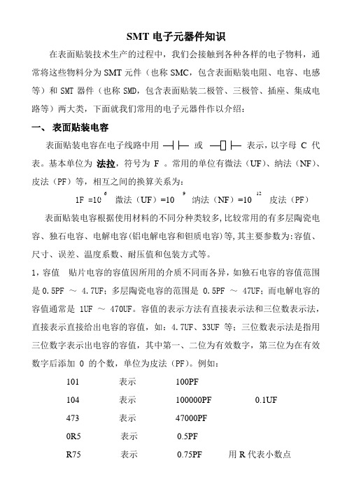
常用的单位有微法(UF)、纳法(NF)、皮法(PF)等,相互之间的换算关系为:1F =10 微法(UF)=10 纳法(NF)=10 皮法(PF)表面贴装电容根据使用材料的不同分种类较多,比较常用的有多层陶瓷电容、独石电容、电解电容(铝电解电容和钽质电容)等,其主要参数为:容值、尺寸、误差、温度系数、耐压值和包装方式等。
1,容值贴片电容的容值因所用的介质不同而各异,如独石电容的容值范围是0.5PF ~ 4.7UF;多层陶瓷电容的范围是 0.5PF ~ 47UF;而电解电容的容值通常是 1UF ~ 470UF。
容值的表示方法有直接表示法和三位数表示法,直接表示直接给出电容的容值,如:4.7UF、33UF等;三位数表示法是指用三位数字表示出电容的容值,其中第一、二位为有效数字,第三位为在有效数字后添加 0 的个数,单位为皮法(PF)。
例如:101 表示100PF104 表示100000PF 0.1UF473 表示47000PF0R5 表示0.5PFR75 表示0.75PF 用R代表小数点6 9 12陶瓷电容 铝电解电容 钽质电容铝电解电容颜色较深(或有负号标记)的一极为负极, 钽质电容颜色较深(或有标记)的一极为正极。
因陶瓷电容其容值没有丝印在元件表面,且同样大小、厚度、颜色的元件,容值大小不一定相同,故对其容值的判定必须借助检测仪表测量。
2,尺寸 不同介质的电容尺寸不同,多层陶瓷贴片电容的尺寸同贴片电阻尺寸,有公制(单位为毫米mm )和英制(单位为英寸)两种尺寸代码,由4位数字组成,前两位数表示电容的长度,后两位数表示电容的宽度。
凌特公司基准芯片参数
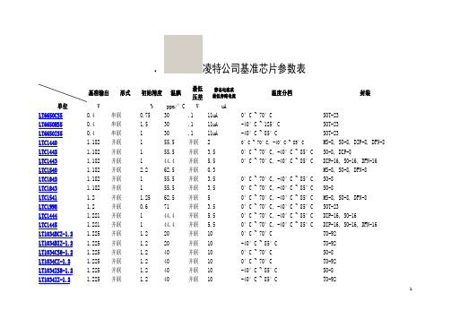
凌特公司基准芯片参数表基准输出形式初始精度温飘最低压差静态电流或最低旁路电流温度分档封装单位V % ppm/°C V uALT6650CS50.4 串联0.75 30 .1 11uA 0°C ~ 70°C SOT-23LT6650HS50.4 串联 1.5 30 .1 11uA -40°C ~ 125°C SOT-23LT6650IS50.4 串联 1 30 .1 11uA -40°C ~ 85°C SOT-23LTC1440 1.182 并联 1 55.5 并联 2 0°C ~ 70°C, -40°C ~ 85°C MS-8, SO-8, DIP-8, DFN-8LTC1442 1.182 并联 1 55.5 并联 3.5 0°C ~ 70°C, -40°C ~ 85°C SO-8, DIP-8LTC1443 1.182 并联 1 44.4 并联 5.5 0°C ~ 70°C, -40°C ~ 85°C DIP-16, SO-16, DFN-16LTC1540 1.182 并联 2.2 62.5 并联0.3 MS-8, SO-8, DFN-8LTC1842 1.182 并联 1 55.5 并联 3.5 0°C ~ 70°C, -40°C ~ 85°C SO-8LTC1843 1.182 并联 1 55.5 并联 3.5 0°C ~ 70°C, -40°C ~ 85°C SO-8LTC1541 1.2 并联 1.25 62.5 并联 5 0°C ~ 70°C, -40°C ~ 85°C MS-8, SO-8, DFN-8LTC1998 1.2 并联0.6 71 并联 3.5 0°C ~ 70°C, -40°C ~ 85°C SOT-23LTC1444 1.221 并联 1 44.4 并联 5.5 0°C ~ 70°C, -40°C ~ 85°C DIP-16, SO-16LTC1445 1.221 并联 1 44.4 并联 5.5 0°C ~ 70°C, -40°C ~ 85°C DIP-16, SO-16, DFN-16LT1034BCZ-1.2 1.225 并联 1.2 20 并联10 0°C ~ 70°C TO-92LT1034BIZ-1.2 1.225 并联 1.2 20 并联10 -40°C ~ 85°C TO-92LT1034CS8-1.2 1.225 并联 1.2 40 并联10 0°C ~ 70°C SO-8LT1034CZ-1.2 1.225 并联 1.2 40 并联10 0°C ~ 70°C TO-92LT1034IS8-1.2 1.225 并联 1.2 40 并联10 -40°C ~ 85°C SO-8LT1034IZ-1.2 1.225 并联 1.2 40 并联10 -40°C ~ 85°C TO-921LT1004IS8-1.2 1.235 并联0.8 20 并联8 -40°C ~ 85°C SO-8LT1004IZ-1.2 1.235 并联0.3 20 并联8 -40°C ~ 85°C TO-92LT1389ACS8-1.25 1.25 并联0.05 10 并联0.6 0°C ~ 70°C SO-8LT1389BCS8-1.25 1.25 并联0.05 20 并联0.6 0°C ~ 70°C SO-8LT1634ACS8-1.25 1.25 并联0.05 10 并联7 0°C ~ 70°C SO-8LT1634AIS8-1.25 1.25 并联0.05 10 并联7 -40°C ~ 85°C SO-8LT1634BCMS8-1.25 1.25 并联0.05 25 并联7 0°C ~ 70°C MS-8LT1634BCS8-1.25 1.25 并联0.05 25 并联7 0°C ~ 70°C SO-8LT1634BIS8-1.25 1.25 并联0.05 25 并联7 -40°C ~ 85°C SO-8LT1634CCZ-1.25 1.25 并联0.2 25 并联7 0°C ~ 70°C TO-92LT1790ACS6-1.25 1.25 串联0.05 10 .1 35 0°C ~ 70°C SOT-23LT1790AIS6-1.25 1.25 串联0.05 10 .1 35 -40°C ~ 85°C SOT-23LT1790BCS6-1.25 1.25 串联0.1 25 .1 35 0°C ~ 70°C SOT-23LT1790BIS6-1.25 1.25 串联0.1 25 .1 35 -40°C ~ 85°C SOT-23LTC6652AHMS8-1.25 1.25 串联0.05 5 .3 350 -40°C ~ 125°C MS-8LTC6652BHMS8-1.25 1.25 串联0.1 10 .3 350 -40°C ~ 125°C MS-8LTC6655BHMS8-1.25 1.25 串联0.025 2 .5 5000 -40°C ~ 125°C MS-8LTC6655CHMS8-1.25 1.25 串联0.05 5 .5 5000 -40°C ~ 125°C MS-8LT1790ACS6-2.048 2.048 串联0.05 10 .1 35 0°C ~ 70°C SOT-23LT1790AIS6-2.048 2.048 串联0.05 10 .1 35 -40°C ~ 85°C SOT-23LT1790BCS6-2.048 2.048 串联0.1 25 .1 35 0°C ~ 70°C SOT-23LT1790BIS6-2.048 2.048 串联0.1 25 .1 35 -40°C ~ 85°C SOT-23LTC6652AHMS8-2.0482.048 串联0.05 5 .3 350 -40°C ~ 125°C MS-8LTC6652BHMS8-2.0482.048 串联0.1 10 .3 350 -40°C ~ 125°C MS-8LTC6655BHMS8-2.0482.048 串联0.025 2 .5 5000 -40°C ~ 125°C MS-8LTC6655CHMS8-2.0482.048 串联0.05 5 .5 5000 -40°C ~ 125°C MS-8LT1004CS8-2.5 2.5 并联0.8 20 并联12 0°C ~ 70°C SO-82LT1004IZ-2.5 2.5 并联0.8 20 并联12 -40°C ~ 85°C TO-92LT1009CMS8 2.5 并联0.2 25 并联400 0°C ~ 70°C MS-8LT1009CZ 2.5 并联0.2 25 并联400 0°C ~ 70°C TO-92LT1009IS8 2.5 并联0.4 35 并联400 -40°C ~ 85°C SO-8LT1009IZ 2.5 并联0.2 35 并联400 -40°C ~ 85°C TO-92LT1009S8 2.5 并联0.4 25 并联400 0°C ~ 70°C SO-8LT1019ACN8-2.5 2.5 串联0.05 5 1.1 650 0°C ~ 70°C DIP-8LT1019ACS8-2.5 2.5 串联0.05 5 1.1 650 0°C ~ 70°C SO-8LT1019AIS8-2.5 2.5 串联0.05 10 1.1 650 -40°C ~ 85°C SO-8LT1019CN8-2.5 2.5 串联0.2 20 1.1 650 0°C ~ 70°C DIP-8LT1019CS8-2.5 2.5 串联0.2 20 1.1 650 0°C ~70°C SO-8LT1019IN8-2.5 2.5 串联0.2 20 1.1 650 -40°C ~ 85°C DIP-8LT1019IS8-2.5 2.5 串联0.2 20 1.1 650 -40°C ~ 85°C SO-8LT1034BCZ-2.5 2.5 并联 1.6 20 并联15 0°C ~ 70°C TO-92LT1034BIZ-2.5 2.5 并联 1.6 20 并联15 -40°C ~ 85°C TO-92LT1034CS8-2.5 2.5 并联 1.6 40 并联15 0°C ~ 70°C SO-8LT1034CZ-2.5 2.5 并联 1.6 40 并联15 0°C ~ 70°C TO-92LT1034IS8-2.5 2.5 并联 1.6 40 并联15 -40°C ~ 85°C SO-8LT1034IZ-2.5 2.5 并联 1.6 40 并联15 -40°C ~ 85°C TO-92LT1389BCS8-2.5 2.5 并联0.05 20 并联0.6 0°C ~ 70°C SO-8LT1460ACN8-2.5 2.5 串联0.075 10 .9 100 0°C ~ 70°C DIP-8LT1460ACS8-2.5 2.5 串联0.075 10 .9 100 0°C ~ 70°C SO-8LT1460BIN8-2.5 2.5 串联0.1 10 .9 100 -40°C ~ 85°C DIP-8LT1460BIS8-2.5 2.5 串联0.1 10 .9 100 -40°C ~ 85°C SO-8LT1460CCMS8-2.5 2.5 串联0.1 15 .9 100 0°C ~ 70°C MS-8LT1460DCN8-2.5 2.5 串联0.1 20 .9 100 0°C ~ 70°C DIP-8LT1460DCS8-2.5 2.5 串联0.1 20 .9 100 0°C ~ 70°C SO-83LT1460EIN8-2.5 2.5 串联0.125 20 .9 100 -40°C ~ 85°C DIP-8LT1460EIS8-2.5 2.5 串联0.125 20 .9 100 -40°C ~ 85°C SO-8LT1460FCMS8-2.5 2.5 串联0.15 25 .9 100 0°C ~ 70°C MS-8LT1460GCZ-2.5 2.5 串联0.25 25 .9 100 0°C ~ 70°C TO-92LT1460GIZ-2.5 2.5 串联0.25 25 .9 100 -40°C ~ 85°C TO-92LT1460HCS3-2.5 2.5 串联0.5 20 .9 100 0°C ~ 70°C SOT-23LT1460JCS3-2.5 2.5 串联0.4 20 .9 100 0°C ~ 70°C SOT-23LT1460KCS3-2.5 2.5 串联0.5 50 .9 100 0°C ~ 70°C SOT-23LT1460LHS8-2.5 2.5 串联0.2 25 .9 100 -40°C ~ 125°C SO-8LT1460MHS8-2.5 2.5 串联0.2 50 .9 100 -40°C ~ 125°C SO-8LT1461ACS8-2.5 2.5 串联0.04 3 .3 35 0°C ~ 70°C SO-8LT1461AIS8-2.5 2.5 串联0.04 3 .3 35 -40°C ~ 85°C SO-8LT1461BCS8-2.5 2.5 串联0.06 7 .3 35 0°C ~ 70°C SO-8LT1461BIS8-2.5 2.5 串联0.06 7 .3 35 -40°C ~ 85°C SO-8LT1461CCS8-2.5 2.5 串联0.1 12 .3 35 0°C ~ 70°C SO-8LT1461CIS8-2.5 2.5 串联0.1 12 .3 35 -40°C ~ 85°C SO-8LT1461DHS8-2.5 2.5 串联0.15 20 .3 35 -40°C ~ 125°C SO-8LT1634ACS8-2.5 2.5 并联0.05 10 并联7 0°C ~ 70°C SO-8LT1634AIS8-2.5 2.5 并联0.05 25 并联7 -40°C ~ 85°C SO-8LT1634BCMS8-2.5 2.5 并联0.05 25 并联7 0°C ~ 70°C MS-8LT1634BCS8-2.5 2.5 并联0.05 25 并联7 0°C ~ 70°C SO-8LT1634BIS8-2.5 2.5 并联0.05 25 并联7 -40°C ~ 85°C SO-8LT1634CCZ-2.5 2.5 并联0.2 25 并联7 0°C ~ 70°C TO-92LT1790ACS6-2.5 2.5 串联0.05 10 .1 35 0°C ~ 70°C SOT-23LT1790AIS6-2.5 2.5 串联0.05 10 .1 35 -40°C ~ 85°C SOT-23LT1790BCS6-2.5 2.5 串联0.1 25 .1 35 0°C ~ 70°C SOT-23LT1790BIS6-2.5 2.5 串联0.1 25 .1 35 -40°C ~ 85°C SOT-23LT6654AHS6-2.5 2.5 串联0.05 3 .055 350 -40°C ~ 85°C SOT-23LT6654AMPS6-2.5 2.5 串联0.05 3 .055 350 -55°C ~ 125°C SOT-234LT6654BHS6-2.5 2.5 串联0.1 6 .055 350 -55°C ~ 125°C SOT-23LT6654BMPS6-2.5 2.5 串联0.1 6 .055 350 -40°C ~ 85°C SOT-23LT6656ACS6-2.5 2.5 串联0.05 10 .5 0.85 0°C ~ 70°C SOT-23LT6656AIS6-2.5 2.5 串联0.05 10 .5 0.85 -40°C ~ 85°C SOT-23LT6656BCS6-2.5 2.5 串联0.1 20 .5 0.85 0°C ~ 70°C SOT-23LT6656BIS6-2.5 2.5 串联0.1 20 .5 0.85 -40°C ~ 85°C SOT-23LT6660HCDC-2.5 2.5 串联0.2 20 .9 115 0°C ~ 70°C DFN-3LT6660JCDC-2.5 2.5 串联0.4 20 .9 115 0°C ~ 70°C DFN-3LT6660KCDC-2.5 2.5 串联0.5 50 .9 115 0°C ~ 70°C DFN-3LTC1258CMS8-2.5 2.5 串联0.21 60 .1 4 0°C ~ 70°C MS-8LTC1258CS8-2.5 2.5 串联0.15 40 .1 4 0°C ~ 70°C SO-8LTC1798CS8-2.5 2.5 串联0.15 15 .1 4 0°C ~ 70°C SO-8LTC6652AHMS8-2.5 2.5 串联0.05 5 .3 350 -40°C ~ 125°C MS-8LTC6652BHMS8-2.5 2.5 串联0.1 10 .3 350 -40°C ~ 125°C MS-8LTC6655BHMS8-2.5 2.5 串联0.025 2 .5 5000 -40°C ~ 125°C MS-8LTC6655CHMS8-2.5 2.5 串联0.05 5 .5 5000 -40°C ~ 125°C MS-8LT1460HCS3-3 3 串联0.2 20 .9 145 0°C ~ 70°C SOT-23LT1460JCS3-3 3 串联0.4 20 .9 145 0°C ~ 70°C SOT-23LT1460KCS3-3 3 串联0.5 50 .9 145 0°C ~ 70°C SOT-23LT1461ACS8-3 3 串联0.04 3 .3 35 0°C ~ 70°C SO-8LT1461AIS8-3 3 串联0.04 3 .3 35 -40°C ~ 85°C SO-8LT1461BCS8-3 3 串联0.1 10 .3 35 0°C ~ 70°C SO-8LT1461BIS8-3 3 串联0.06 7 .3 35 -40°C ~ 85°C SO-8LT1461CCS8-3 3 串联0.1 12 .3 35 0°C ~ 70°C SO-8LT1461CIS8-3 3 串联0.1 12 .3 35 -40°C ~ 85°C SO-8LT1461DHS8-3 3 串联0.2 20 .3 35 -40°C ~ 125°C SO-8LT1790ACS6-3 3 串联0.05 10 .1 35 0°C ~ 70°C SOT-23LT1790AIS6-3 3 串联0.05 10 .1 35 -40°C ~ 85°C SOT-23LT1790BCS6-3 3 串联0.1 25 .1 35 0°C ~ 70°C SOT-235LT1790BIS6-3 3 串联0.1 25 .1 35 -40°C ~ 85°C SOT-23LT6660HCDC-3 3 串联0.2 20 .9 145 0°C ~ 70°C DFN-3LT6660JCDC-3 3 串联0.4 20 .9 145 0°C ~ 70°C DFN-3LT6660KCDC-3 3 串联0.5 50 .9 145 0°C ~ 70°C DFN-3LTC1258CMS8-3 3 串联0.15 60 .1 4 0°C ~ 70°C MS-8LTC1258CS8-3 3 串联0.15 40 .1 4 0°C ~ 70°C SO-8LTC1798CS8-3 3 串联0.15 15 .1 4 0°C ~ 70°C SO-8LTC6652AHMS8-3 3 串联0.05 5 .3 350 -40°C ~ 125°C MS-8LTC6652BHMS8-3 3 串联0.1 10 .3 350 -40°C ~ 125°C MS-8LTC6655BHMS8-3 3 串联0.025 2 .5 5000 -40°C ~ 125°C MS-8LTC6655CHMS8-3 3 串联0.05 5 .5 5000 -40°C ~ 125°C MS-8LT1460HCS3-3.3 3.3 串联0.2 20 .9 145 0°C ~ 70°C SOT-23LT1460JCS3-3.3 3.3 串联0.4 20 .9 145 0°C ~ 70°C SOT-23LT1460KCS3-3.3 3.3 串联0.5 50 .9 145 0°C ~ 70°C SOT-23LT1461ACS8-3.3 3.3 串联0.04 3 .3 35 0°C ~ 70°C SO-8LT1461AIS8-3.3 3.3 串联0.04 3 .3 35 -40°C ~ 85°C SO-8LT1461BCS8-3.3 3.3 串联0.1 10 .3 35 0°C ~ 70°C SO-8LT1461BIS8-3.3 3.3 串联0.1 10 .3 35 -40°C ~ 85°C SO-8LT1461CCS8-3.3 3.3 串联0.1 12 .3 35 0°C ~ 70°C SO-8LT1461CIS8-3.3 3.3 串联0.1 12 .3 35 -40°C ~ 85°C SO-8LT1461DHS8-3.3 3.3 串联0.2 20 .3 35 -40°C ~ 125°C SO-8LT1790ACS6-3.3 3.3 串联0.05 10 .1 35 0°C ~ 70°C SOT-23LT1790AIS6-3.3 3.3 串联0.05 10 .1 35 -40°C ~ 85°C SOT-23LT1790BCS6-3.3 3.3 串联0.1 25 .1 35 0°C ~ 70°C SOT-23LT1790BIS6-3.3 3.3 串联0.1 25 .1 35 -40°C ~ 85°C SOT-23LT6660HCDC-3.3 3.3 串联0.2 20 .9 145 0°C ~ 70°C DFN-3LT6660JCDC-3.3 3.3 串联0.4 20 .9 145 0°C ~ 70°C DFN-3LT6660KCDC-3.3 3.3 串联0.5 50 .9 145 0°C ~ 70°C DFN-3LTC6652AHMS8-3.3 3.3 串联0.05 5 .3 350 -40°C ~ 125°C MS-86LTC6655BHMS8-3.3 3.3 串联0.025 2 .5 5000 -40°C ~ 125°C MS-8LTC6655CHMS8-3.3 3.3 串联0.05 5 .5 5000 -40°C ~ 125°C MS-8LT1389BCS8-4.096 4.096 并联0.075 50 并联0.6 0°C ~ 70°C SO-8LT1461ACS8-4 4.096 串联0.04 3 .3 35 0°C ~ 70°C SO-8LT1461AIS8-4 4.096 串联0.04 3 .3 35 -40°C ~ 85°C SO-8LT1461BCS8-4 4.096 串联0.06 7 .3 35 0°C ~ 70°C SO-8LT1461BIS8-4 4.096 串联0.1 10 .3 35 -40°C ~ 85°C SO-8LT1461CCS8-4 4.096 串联0.1 12 .3 35 0°C ~ 70°C SO-8LT1461CIS8-4 4.096 串联0.1 12 .3 35 -40°C ~ 85°C SO-8LT1461DHS8-4 4.096 串联0.2 20 .3 35 -40°C ~ 125°C SO-8LT1634ACS8-4.096 4.096 并联0.05 10 并联7 0°C ~ 70°C SO-8LT1634AIS8-4.096 4.096 并联0.05 10 并联7 -40°C ~ 85°C SO-8LT1634BCS8-4.096 4.096 并联0.05 25 并联7 0°C ~ 70°C SO-8LT1634BIS8-4.096 4.096 并联0.05 25 并联7 -40°C ~ 85°C SO-8LT1634CCZ-4.096 4.096 并联0.2 25 并联7 0°C ~ 70°C TO-92LT1790ACS6-4.096 4.096 串联0.05 10 .1 35 0°C ~ 70°C SOT-23LT1790AIS6-4.096 4.096 串联0.05 10 .1 35 -40°C ~ 85°C SOT-23LT1790BCS6-4.096 4.096 串联0.1 25 .1 35 0°C ~ 70°C SOT-23LT1790BIS6-4.096 4.096 串联0.1 25 .1 35 -40°C ~ 85°C SOT-23LTC1258CMS8-4.1 4.096 串联0.15 40 .1 4 0°C ~ 70°C MS-8LTC1258CS8-4.1 4.096 串联0.15 40 .1 4 0°C ~ 70°C SO-8LTC1798CS8-4.1 4.096 串联0.15 15 .1 4 0°C ~ 70°C SO-8LTC6652AHMS8-4.0964.096 串联0.05 5 .3 350 -40°C ~ 125°C MS-8LTC6652BHMS8-4.0964.096 串联0.1 10 .3 350 -40°C ~ 125°C MS-8LTC6655BHMS8-4.0964.096 串联0.025 2 .5 5000 -40°C ~ 125°C MS-8LTC6655CHMS8-4.0964.096 串联0.05 5 .5 5000 -40°C ~ 125°C MS-8LT1019ACN8-4.5 4.5 串联0.05 5 1.1 650 0°C ~ 70°C DIP-8LT1019CN8-4.5 4.5 串联0.2 20 1.1 650 0°C ~ 70°C DIP-87LT1019IN8-4.5 4.5 串联0.2 5 1.1 650 -40°C ~ 85°C DIP-8LT1019ACN8-5 5 串联0.05 5 1.1 650 0°C ~ 70°C DIP-8LT1019ACS8-5 5 串联0.05 3 1.1 650 0°C ~ 70°C SO-8LT1019AIS8-5 5 串联0.05 3 1.1 650 -40°C ~ 85°C SO-8LT1019CN8-5 5 串联0.2 5 1.1 650 0°C ~ 70°C DIP-8LT1019CS8-5 5 串联0.2 20 1.1 650 0°C ~ 70°C SO-8LT1019IN8-5 5 串联0.2 5 1.1 650 -40°C ~ 85°C DIP-8LT1019IS8-5 5 串联0.2 20 1.1 650 -40°C ~ 85°C SO-8LT1021BCH-5 5 串联 1 5 2.2 800 0°C ~ 70°C to-5LT1021BCN8-5 5 串联 1 5 2.2 800 0°C ~ 70°C DIP-8LT1021BMH-5 5 串联 1 5 2.2 800 -55°C ~ 125°C TO-5LT1021CCH-5 5 串联0.05 20 2.2 800 0°C ~ 70°C TO-5LT1021CCN8-5 5 串联0.05 20 2.2 800 0°C ~ 70°C DIP-8LT1021CIN8-5 5 串联0.05 20 2.2 800 -40°C ~ 85°C DIP-8LT1021CMH-5 5 串联0.05 20 2.2 800 -55°C ~ 125°C TO-5LT1021DCN8-5 5 串联 1 20 2.2 800 0°C ~ 70°C DIP-8LT1021DCS8-5 5 串联 1 20 2.2 800 0°C ~ 70°C SO-8LT1021DIN8-5 5 串联 1 20 2.2 800 -40°C ~ 85°C DIP-8LT1027BCN8-5 5 串联0.05 1 3 2200 0°C ~ 70°C DIP-8LT1027CCN8-5 5 串联0.05 2 3 2200 0°C ~ 70°C DIP-8LT1027CCS8-5 5 串联0.05 2 3 2200 0°C ~ 70°C SO-8LT1027DCN8-5 5 串联0.05 2 3 2200 0°C ~ 70°C DIP-8LT1027DCS8-5 5 串联0.05 2 3 2200 0°C ~ 70°C SO-8LT1027ECN8-5 5 串联0.1 3 3 2200 0°C ~ 70°C DIP-8LT1027ECS8-5 5 串联0.1 3 3 2200 0°C ~ 70°C SO-8LT1029ACZ 5 并联0.2 20 并联700 0°C ~ 70°C TO-92LT1029CZ 5 并联 1 34 并联700 0°C ~ 70°C TO-92LT1236ACN8-5 5 串联0.05 2 1 800 0°C ~ 70°C DIP-88LT1236BCN8-5 5 串联0.1 5 1 800 0°C ~ 70°C DIP-8LT1236BCS8-5 5 串联0.1 5 1 800 0°C ~ 70°C SO-8LT1236BIN8-5 5 串联0.1 15 1 800 -40°C ~ 85°C DIP-8LT1236BIS8-5 5 串联0.1 5 1 800 -40°C ~ 85°C SO-8LT1236CCN8-5 5 串联0.1 10 1 800 0°C ~ 70°C DIP-8LT1236CCS8-5 5 串联0.1 10 1 800 0°C ~ 70°C SO-8LT1236CIN8-5 5 串联0.1 10 1 800 -40°C ~ 85°C DIP-8LT1236CIS8-5 5 串联0.1 10 1 800 -40°C ~ 85°C SO-8LT1389BCS8-5 5 并联0.075 50 并联0.6 0°C ~ 70°C SO-8LT1460ACN8-5 5 串联0.075 5 .9 125 0°C ~ 70°C DIP-8LT1460ACS8-5 5 串联0.075 10 .9 125 0°C ~ 70°C SO-8LT1460BIN8-5 5 串联0.1 5 .9 125 -40°C ~ 85°C DIP-8LT1460BIS8-5 5 串联0.1 10 .9 125 -40°C ~ 85°C SO-8LT1460CCMS8-5 5 串联0.1 15 .9 125 0°C ~ 70°C MS-8LT1460DCN8-5 5 串联0.125 10 .9 125 0°C ~ 70°C DIP-8LT1460DCS8-5 5 串联0.125 10 .9 125 0°C ~ 70°C SO-8LT1460EIN8-5 5 串联0.125 10 .9 125 -40°C ~ 85°C DIP-8LT1460EIS8-5 5 串联0.125 20 .9 125 -40°C ~ 85°C SO-8LT1460FCMS8-5 5 串联0.15 25 .9 125 0°C ~ 70°C MS-8LT1460GCZ-5 5 串联0.25 25 .9 125 0°C ~ 70°C TO-92LT1460GIZ-5 5 串联0.25 25 .9 125 -40°C ~ 85°C TO-92LT1460HCS3-5 5 串联0.2 20 .9 125 0°C ~ 70°C SOT-23LT1460JCS3-5 5 串联0.4 20 .9 125 0°C ~ 70°C SOT-23LT1460KCS3-5 5 串联0.5 50 .9 125 0°C ~ 70°C SOT-23LT1460LHS8-5 5 串联0.2 20 .9 125 -40°C ~ 125°C SO-8LT1460MHS8-5 5 串联0.2 50 .9 125 -40°C ~ 125°C SO-8LT1461ACS8-5 5 串联0.04 3 .3 35 0°C ~ 70°C SO-89LT1461BIS8-5 5 串联0.06 7 .3 35 -40°C ~ 85°C SO-8LT1461CCS8-5 5 串联0.1 12 .3 35 0°C ~ 70°C SO-8LT1461CIS8-5 5 串联0.1 12 .3 35 -40°C ~ 85°C SO-8LT1461DHS8-5 5 串联0.2 20 .3 35 -40°C ~ 125°C SO-8LT1634ACS8-5 5 并联0.05 10 并联7 0°C ~ 70°C SO-8LT1634AIS8-5 5 并联0.05 10 并联7 -40°C ~ 85°C SO-8LT1634BCS8-5 5 并联0.05 25 并联7 0°C ~ 70°C SO-8LT1634BIS8-5 5 并联0.05 25 并联7 -40°C ~ 85°C SO-8LT1634CCZ-5 5 并联0.2 25 并联7 0°C ~ 70°C TO-92LT1790ACS6-5 5 串联0.05 10 .1 35 0°C ~ 70°C SOT-23LT1790AIS6-5 5 串联0.05 10 .1 35 -40°C ~ 85°C SOT-23LT1790BCS6-5 5 串联0.1 25 .1 35 0°C ~ 70°C SOT-23LT1790BIS6-5 5 串联0.1 25 .1 35 -40°C ~ 85°C SOT-23LT6660HCDC-5 5 串联0.2 20 .9 160 0°C ~ 70°C DFN-3LT6660JCDC-5 5 串联0.4 20 .9 160 0°C ~ 70°C DFN-3LT6660KCDC-5 5 串联0.5 50 .9 160 0°C ~ 70°C DFN-3LTC1258CMS8-5 5 串联0.18 60 .1 4 0°C ~ 70°C MS-8LTC1258CS8-5 5 串联0.15 40 .1 4 0°C ~ 70°C SO-8LTC1798CS8-5 5 串联0.15 15 .1 4 0°C ~ 70°C SO-8LTC6652AHMS8-5 5 串联0.05 5 .3 350 -40°C ~ 125°C MS-8LTC6652BHMS8-5 5 串联0.1 10 .3 350 -40°C ~ 125°C MS-8LTC6655BHMS8-5 5 串联0.025 2 .5 5000 -40°C ~ 125°C MS-8LTC6655CHMS8-5 5 串联0.05 5 .5 5000 -40°C ~ 125°C MS-8LT1021BCN8-77 串联0.71 5 1.5 800 0°C ~ 70°C DIP-8LT1021DCN8-77 串联0.71 20 1.5 800 0°C ~ 70°C DIP-8LT1021DCS8-77 串联0.71 20 1.5 800 0°C ~ 70°C SO-8LTZ1000ACH/CH7.2 Super Zener 4 0.05 N/A 250 -55°C ~ 125°C to-510LT1019CS8-1010 串联0.2 5 1.1 650 0°C ~ 70°C SO-8LT1019IN8-1010 串联0.2 20 1.1 650 -40°C ~85°C DIP-8LT1021BCN8-1010 串联0.5 5 1.5 800 0°C ~ 70°C DIP-8LT1021BMH-1010 串联 1 5 2.2 800 -55°C ~ 125°C TO-5LT1021CCN8-1010 串联0.05 5 2.2 800 0°C ~ 70°C DIP-8LT1021CIN8-1010 串联0.05 5 2.2 800 -40°C ~ 85°C DIP-8LT1021DCN8-1010 串联0.5 5 2.2 800 0°C ~ 70°C DIP-8LT1021DCS8-1010 串联0.5 20 1.5 800 0°C ~ 70°C SO-8LT1021DIN8-1010 串联0.05 5 2.2 800 -40°C ~ 85°C DIP-8LT1031BCH10 串联0.05 5 1 1200 0°C ~ 70°C TO-39LT1031BMH10 串联0.05 5 1 1200 -55°C ~ 125°C TO-39LT1031CCH10 串联0.1 15 1 1200 0°C ~ 70°C TO-39LT1031DCH10 串联0.2 25 1 1200 0°C ~ 70°C TO-39LT1031DMH10 串联0.2 25 1 1200 -55°C ~ 125°C TO-39LT1236ACN8-1010 串联0.05 2 1 800 0°C ~ 70°C DIP-8LT1236ACS8-1010 串联0.05 5 1 800 0°C ~ 70°C SO-8LT1236AIN8-1010 串联0.05 2 1 800 -40°C ~ 85°C DIP-8LT1236AIS8-1010 串联0.05 2 1 800 -40°C ~ 85°C SO-8LT1236BCN8-1010 串联0.1 5 1 800 0°C ~ 70°C DIP-8LT1236BCS8-1010 串联0.1 5 1 800 0°C ~ 70°C SO-8LT1236BIN8-1010 串联0.1 5 1 800 -40°C ~ 85°C DIP-8LT1236BIS8-1010 串联0.1 5 1 800 -40°C ~ 85°C SO-8LT1236CCN8-1010 串联0.1 10 1 800 0°C ~ 70°C DIP-8LT1236CCS8-1010 串联0.1 10 1 800 0°C ~ 70°C SO-8LT1236CIN8-1010 串联0.1 10 1 800 -40°C ~ 85°C DIP-8LT1236CIS8-1010 串联0.1 10 1 800 -40°C ~ 85°C SO-8LT1460ACN8-1010 串联0.075 10 .9 190 0°C ~ 70°C DIP-811LT1460BIS8-1010 串联0.1 10 .9 190 -40°C ~ 85°C SO-8LT1460CCMS8-1010 串联0.1 7 .9 190 0°C ~ 70°C MS-8LT1460DCN8-1010 串联0.1 10 .9 190 0°C ~ 70°C DIP-8LT1460DCS8-1010 串联0.1 20 .9 190 0°C ~ 70°C SO-8LT1460EIN8-1010 串联0.125 20 .9 190 -40°C ~ 85°C DIP-8LT1460EIS8-1010 串联0.125 20 .9 190 -40°C ~ 85°C SO-8LT1460FCMS8-1010 串联0.15 25 .9 190 0°C ~ 70°C MS-8LT1460GCZ-1010 串联0.25 25 .9 190 0°C ~ 70°C TO-92LT1460GIZ-1010 串联0.25 25 .9 190 -40°C ~ 85°C TO-92LT1460HCS3-1010 串联0.2 20 1.1 190 0°C ~ 70°C SOT-23LT1460JCS3-1010 串联0.4 20 1.1 190 0°C ~ 70°C SOT-23LT1460KCS3-1010 串联0.5 50 1.1 190 0°C ~ 70°C SOT-23LT6660HCDC-1010 串联0.2 20 .9 215 0°C ~ 70°C DFN-3LT6660JCDC-1010 串联0.4 20 .9 215 0°C ~ 70°C DFN-3LT6660KCDC-1010 串联0.5 50 .9 215 0°C ~ 70°C DFN-3LT1431CN8可调并联0.4 30 并联600 0°C ~ 70°C DIP-8LT1431CS8可调并联0.4 30 并联600 0°C ~ 70°C SO-8LT1431CZ可调并联0.4 30 并联600 0°C ~ 70°C TO-92LT1431IN8可调并联0.4 30 并联600 -40°C ~ 85°C DIP-8LT1431IS8可调并联0.4 30 并联600 -40°C ~ 85°C SO-8LT1431IZ可调并联0.4 50 并联600 -40°C ~ 85°C TO-9212。
半导体集成电路封装术语-最新国标

半导体集成电路封装术语1 范围本文件规定了半导体集成电路封装在生产制造、工程应用和产品交验等方面使用的基本术语。
本文件适用于与半导体集成电路封装相关的生产、科研、教学和贸易等方面的应用。
2 规范性引用文件下列文件中的内容通过文中的规范性引用而构成本文件必不可少的条款。
其中,注日期的引用文件,仅该日期对应的版本适用于本文件;不注日期的引用文件,其最新版本(包括所有的修改单)适用于本文件。
GB/T 7092 半导体集成电路外形尺寸GB/T 9178 集成电路术语3 通用术语GB/T 9178界定的以及下列术语和定义适用于本文件。
3.1封装 package半导体集成电路的全包封或部分包封体,它提供:——机械保护;——环境保护;——外形尺寸。
封装可以包含或提供引出端,它对集成电路的热性能产生影响。
3.2底座 header封装体中用来安装半导体芯片并已具备了芯片焊接(粘接)、引线键合和引出端等功能的部分,它是封装结构的基体。
3.3底板 base在陶瓷或金属封装中,构成底座的一种片状陶瓷或金属零件。
3.4盖板(管帽) cap在陶瓷封装或金属底座上,采用金属或陶瓷制成片状或帽状结构,封接后对整个封装形成密封的一个零件。
3.5密封环 seal ring装在陶瓷封装表面上的一个金属或陶瓷件,在其上可焊接一个用于密封的盖板。
3.6引线框架 leadframes采用冲制或刻蚀工艺制造,使具有一定几何图形和规定外形尺寸,提供陶瓷封装、塑料封装或陶瓷熔封引出线的一个或一组金属零件。
引线框架各部位名称见图1a)、图1b)和图1c)。
a)陶瓷封装引线框架b)塑料封装引线框架(成型后)c ) 陶瓷熔封封装引线框架图1 引线框架3.7引线 lead安装在封装底板上用于电接触的金属线。
3.8引岀端 terminal封装上电接触的外接点,通常指引出线或端子。
3.9引岀端识别标志 terminal visual index鉴别第一引出端位置的参考特征(例如标记、凹槽、缺口、切角、凹陷或键等)。
PWD5F60 高压集成电路说明书
PWD5F60PWD5F60TRVFQFPN 15 x 7 x 1 mmFeatures•Power system-in-package integrating gate drivers and high-voltage power MOSFETs –R DS(ON) = 1.38 Ω–BV DSS = 600 V•Suitable for operating as –full bridge –dual independent half bridges•UVLO protection on low-side and high-side• 3.3 V to 15 V compatible inputs with hysteresis and pull-down •Internal bootstrap diode •Uncommitted comparators •Adjustable dead-time •Bill of material reduction•Very compact and simplified layout •Flexible, easy and fast designApplications•Industrial fans and pumps•Cooking hoods and gas heaters •Blowers•Industrial drives and factory automation •Power supply unitsDescriptionThe PWD5F60 is an advanced power system-in package integrating gate drivers and four N-channel power MOSFETs in dual half-bridge configuration.The integrated power MOSFETs have R DS(ON) of 1.38 Ω and 600 V drain-source breakdown voltage, while the embedded gate drivers high side can be easilysupplied by the integrated bootstrap diode. The high integration of the device allows to efficiently drive loads in a tiny space.The PWD5F60 accepts a supply voltage (VCC) extending over a wide range (10 V to 20 V) and also features UVLO protection on both the lower and upper driving sections, preventing the power switches from operating in low efficiency or dangerous conditions.The input pins extended range allows easy interfacing with microcontrollers, DSP units or Hall effect sensors.The PWD5F60 embeds two uncommitted comparators available for protections against overcurrent, overtemperature, etc.The PWD5F60 operates in the industrial temperature range, -40 °C to 125 °C.The device is available in a compact VFQFPN package.High density power driver - high voltage full bridge with integrated comparatorsPWD5F60Datasheet1Block diagramFigure 2.Block diagramPWD5F60Block diagram2Pin description and connection diagramFigure 3. Pin connection (top view)38 S D 239 r e s e r v e dGND1EPAD440 G N D 241 P W M 242 V C C 243 D T 244 N C45 C P O U T 246 G N D 2OUT1EPAD1EPAD3GND2VSVSOUT2EPAD5EPAD6EPAD2S D 1 15G N D 1 16P W M 1 17V C C 1 18D T 1 19N C 20C P O U T 1 21G N D 1 22CP+2 1CP-2 2SENSE2 3GND2 4OUT2 5VS 9OUTB1 12BOOT1 13OUT2 623 CP+124 CP-125 SENSE126 GND130 OUT131 VS 34 OUTB235 BOOT236 reserved 37 IN229 OUT128 OUT127 OUT132 VS 33 VS E P 7OUT2 7OUT2 8VS 10VS 11IN1 14PWD5F60Pin description and connection diagramPWD5F60Pin list 2.1Pin listTable 1. Pin description1.EPAD3 is internally connected with EPAD6. No connection is required at PCB level.2.Pin 12 is internally connected to OUT1. No connection is required at PCB level.3.Pin 34 is internally connected to OUT2. No connection is required at the PCB level. Use pin 34 for bootstrap capacitorconnection only.PWD5F60Electrical data 3Electrical data3.1Absolute maximum ratingsTable 2. Absolute maximum ratings1.T CB is temperature of case bottom pad.2.Characterized, not tested in production.3.The value specified by design factor, pulse duration limited by max junction temperature and SOA.4.Value calculated based on thermal resistance, power uniformly distributed over the four power MOSFETs, still air.5.Actual applicative board max dissipation could be higher or lower depending on layout and cooling techniques.3.2Recommended operating conditionsTable 3. Recommended operating conditionsPWD5F60Thermal data1.At least one of the comparator inputs must be lower than2.5 V to guarantee proper operation.3.3Thermal dataTable 4. Thermal data1.The junction to ambient thermal resistance is obtained simulating the device mounted on a 2s2p (4-layer) FR4 board as perJESD51-5,7 with 4 thermal vias for each MOSFET pad. Power dissipation is uniformly distributed over the four powerMOSFETs.PWD5F60Electrical characteristics 4Electrical characteristics4.1DriverVCCx = 15 V; T J = 25 °C, unless otherwise specified.Table 5. Driver electrical characteristicsPWD5F60Driver1.R BD(on) is tested in the following way: R BD(on) = [(VCC - V BOOTa) - (VCC - V BOOTb)] / [Ia - Ib], where: Ia is BOOT pin currentwhen V BOOT = V BOOTa; Ib is BOOT pin current when V BOOT = V BOOTb.2.The comparator is disabled when VCC is in UVLO condition.3.Tested at wafer level before packaging4.MDT = | DTLH – DTHL |.Figure 4. Typical dead time vs. R DT resistor valueD T (µs )Formula for approximate R DT calculation (typ.): R DT [kΩ] = 92.2 x DT[µs] - 16.650100150200250300R DT (kΩ)00.51.01.52.02.53.03.54.2Power MOSFETVCCx = 15 V; T J = 25 °C, unless otherwise specified.Table 6. Power MOSFET electrical characteristics1.Tested at the wafer level before packaging.PWD5F60Power MOSFET5Device characterization valuesTable 7., Table 8. and the electrical characteristics curves (from Figure 6. to Figure 15.) represent typical valuesbased on characterization and simulation results and are not subject to production tests.Table 7. Power MOSFET characterization valuesTable 8. Inductive load switching characteristics1.t(on) and t(off) include the propagation delay time of the internal driver2.t C(on) and t C(off) are the switching times of MOSFET itself under the internally given gate driving conditionsFigure 5.Switching time definition6Functional description6.1Logic inputsThe PWD5F60 full bridge features two identical half-bridge sections. Each section has three logic inputs to control the internal high-side and low-side MOSFETs.Table 9. Truth tableThe logic inputs have internal pull-down resistors. The purpose of these resistors is to set a defined logic level if,for example, there is an interruption on the logic lines or the controller outputs are in tri-state conditions.6.2Bootstrap structureBootstrap circuitry is typically used to supply the high-voltage section. This function is normally accomplished witha high-voltage fast recovery diode, as shown in Figure 16. (side a).In the PWD5F60, a patented integrated structure replaces the external diode. The structure consists of a series of low-voltage diodes and a high-voltage DMOS, driven synchronously by the low-side driver (LVG), as shown in Figure 16. (side b). An internal bootstrap provides the DMOS driving voltage. The integrated diode structure is actively turned on and guarantees best performance only when the low-side driver is on.In applications where the control strategy requires recharging the bootstrap capacitor even when the low-side driver is off, the use of an external bootstrap diode in parallel to the integrated structure is possible.Figure 16.Bootstrap structureD BOOTFunctional descriptionSupply pins and UVLO function6.3Supply pins and UVLO functionThe VCCx supply pin supplies current to the low-side section of the gate driver and to the integrated bootstrapdiode used to charge the bootstrap capacitor. During output commutations, the average current used to providegate charge to the high-side and low-side MOSFETs flow through these pins.The VCC1 and VCC2 pins separately supply power to the two drivers, even if they are usually connected togetherat the power supply in final applications.The PWD5F60 VCCx supply voltage is continuously monitored by undervoltage lockout (UVLO) circuits that turnthe high-side and low-side MOSFETs off when the supply voltage falls below the VCC_thOFF threshold. The VCCxUVLO circuitry turns on the high-side or low-side MOSFET according to the input status as soon as the supplyvoltage rises above the VCC_thON voltage. VCC_hys hysteresis is provided for noise rejection purposes.Two separate UVLO circuits monitor VCC1 and VCC2 so that when a UVLO occurs on a single rail, only thecorresponding half bridge MOSFETs are turned off.The PWD5F60 V BO supply voltages are also continuously monitored by two dedicated V BO UVLO circuits thatturn the corresponding high-side MOSFET off when the supply voltage falls below the V BO_thOFF threshold. TheUVLO circuitry allows turning the high-side MOSFET on again, according to input edges, as soon as the V BOsupply voltage rises above the V BO_thON voltage. A V BO_hys hysteresis is provided for noise rejection purposes.6.4Dead timeThe PWD5F60 automatically inserts a DT dead time on each half bridge. This avoids shoot-through as aMOSFET gate discharges completely before charging starts on the other MOSFET gate.The DT value is set by the resistor placed between the DTx pin and GNDx, as shown in Figure 4..The minimum dead time value set with a 0 Ω resistor is normally sufficient to avoid shoot-through between highside and low side.Some applications, like those operating with soft turn-on commutations at low current seeking maximumefficiency, might benefit from a longer dead time. The PWD5F60 lets you set the dead time for each half bridge formaximum flexibility.7Typical application diagramsFigure 17.Generic applicationfrom CONTROLLERto CONTROLLERFigure 18.Current mode motor controlHall effect sensorShutdownSpeed control voltage referenceTypical application diagrams8Package informationIn order to meet environmental requirements, ST offers these devices in different grades of ECOPACK ®packages, depending on their level of environmental compliance. ECOPACK ® specifications, grade definitions and product status are available at: . ECOPACK ® is an ST trademark.8.1VFQFPN 15 x 7 x 1 mm package informationThe package outline CAD file is available upon request.Figure 19. VFQFPN 15 x 7 x 1 mm package dimensions – drawing top and side viewA A Package informationFigure 20. VFQFPN 15 x 7 x 1 mm package dimensions – drawing bottom viewFigure 21. VFQFPN 15 x 7 x 1 mm package dimensions – exposed pads details(116°)232744732333428293031Table 10. VFQFPN 15 x 7 x 1 mm package mechanical dataVFQFPN 15 x 7 x 1 mm package informationNote:•VFQFPN stands for Thermally Enhanced Very thin Fine pitch Quad Flat Packages No lead.•Dimensioning and tolerances comply with ASME Y14.5-2009.•All dimensions are in millimetres.• A variable pitch is applied on leads. Please refer to Figure 20. for lead position details.•The leads size is comprehensive of the thickness of the leads finishing material.•Dimensions do not include mold protrusion, not to exceed 0.15 mm.•Package outline does not include eventual metal burr dimensions.Ordering information 9Ordering informationTable 11. Device summaryRevision historyTable 12. Document revision historyContentsContents1Block diagram (2)2Pin description and connection diagram (3)2.1Pin list (3)3Electrical data (5)3.1Absolute maximum ratings (5)3.2Recommended operating conditions (5)3.3Thermal data (6)4Electrical characteristics (7)4.1Driver (7)4.2Power MOSFET (9)5Device characterization values (10)6Functional description (14)6.1Logic inputs (14)6.2Bootstrap structure (14)6.3Supply pins and UVLO function (14)6.4Dead time (15)7Typical application diagrams (16)8Package information (17)8.1VFQFPN 15 x 7 x 1 mm package information (17)9Ordering information (21)Revision history (22)List of figuresFigure 2. Block diagram (2)Figure 3. Pin connection (top view) (3)Figure 4. Typical dead time vs. R DT resistor value (9)Figure 5. Switching time definition (11)Figure 6. Normalized gate threshold voltage vs temperature (11)Figure 7. Normalized drain-source breakdown voltage vs. temperature (11)Figure 8. Static drain-source on-resistance (12)Figure 9. Normalized on-resistance vs temperature (12)Figure 10. Transfer characteristics (12)Figure 11. Output characteristics (12)Figure 12. Static source-drain diode forward characteristics (12)Figure 13. Gate charge vs. gate-source voltage (12)Figure 14. MOSFET capicatance variations (13)Figure 15. MOSFET output capacitance stored energy (13)Figure 16. Bootstrap structure (14)Figure 17. Generic application (16)Figure 18. Current mode motor control (16)Figure 19. VFQFPN 15 x 7 x 1 mm package dimensions – drawing top and side view (17)Figure 20. VFQFPN 15 x 7 x 1 mm package dimensions – drawing bottom view (18)Figure 21. VFQFPN 15 x 7 x 1 mm package dimensions – exposed pads details (19)List of tablesTable 1. Pin description (4)Table 2. Absolute maximum ratings (5)Table 3. Recommended operating conditions (5)Table 4. Thermal data (6)Table 5. Driver electrical characteristics (7)Table 6. Power MOSFET electrical characteristics (9)Table 7. Power MOSFET characterization values (10)Table 8. Inductive load switching characteristics (10)Table 9. Truth table (14)Table 10. VFQFPN 15 x 7 x 1 mm package mechanical data (19)Table 11. Device summary (21)Table 12. Document revision history (22)IMPORTANT NOTICE – PLEASE READ CAREFULLYSTMicroelectronics NV and its subsidiaries (“ST”) reserve the right to make changes, corrections, enhancements, modifications, and improvements to ST products and/or to this document at any time without notice. Purchasers should obtain the latest relevant information on ST products before placing orders. ST products are sold pursuant to ST’s terms and conditions of sale in place at the time of order acknowledgement.Purchasers are solely responsible for the choice, selection, and use of ST products and ST assumes no liability for application assistance or the design of Purchasers’ products.No license, express or implied, to any intellectual property right is granted by ST herein.Resale of ST products with provisions different from the information set forth herein shall void any warranty granted by ST for such product.ST and the ST logo are trademarks of ST. All other product or service names are the property of their respective owners.Information in this document supersedes and replaces information previously supplied in any prior versions of this document.© 2018 STMicroelectronics – All rights reservedPWD5F60PWD5F60TR。
芯片 加强绝缘 标准

芯片的加强绝缘标准通常涉及到过压等级的概念。
以系统电压为600V的情况为例,如果要满足过压等级Ⅲ的基本绝缘,瞬态隔离电压需要达到6000V;若要加强绝缘,瞬态隔离电压则需达到8000V。
另外,当碳化硅MOS使用在800V的母线电压时,如果要满足等级Ⅱ的基本绝缘,那么VIOTM (一种电压参数)达到6000V即可,若要加强绝缘,则VIOTM得达到8000V;而如果需要满足等级Ⅲ的基本绝缘,VIOTM要达到8000V,这时加强绝缘的话,VIOTM就需要达到12000V。
请注意,以上标准不允许插值,可以就高。
同时,这些标准可能会因具体芯片和应用场景的不同而有所变化,因此在实际操作中,应参照具体芯片的技术手册和相关行业标准来确定加强绝缘的标准。
- 1、下载文档前请自行甄别文档内容的完整性,平台不提供额外的编辑、内容补充、找答案等附加服务。
- 2、"仅部分预览"的文档,不可在线预览部分如存在完整性等问题,可反馈申请退款(可完整预览的文档不适用该条件!)。
- 3、如文档侵犯您的权益,请联系客服反馈,我们会尽快为您处理(人工客服工作时间:9:00-18:30)。
优化可以获得软开关的效果,有助于抑制开关噪声。
2.4 封装技术( 降低热阻)
采用与 50 A 模块相同的尺寸,而将额定电流
提高到 75 A,模块的发热量会增加,所以必须改善 DIPIPMTM 的散热特性。这里以具有优异热传导特
性的绝缘薄膜取代传统的绝缘树脂,使得模块基
图 2 折衷曲线特性
板和硅片间的热阻比传统结构减小了 30%,有效
在 75 A/600 V 第 4 代 DIPIPMTM 模块内,IGBT 硅片采用图 1a 所示的全栅型 CSTBTTM,通过优化的 内置驱动 IC,可获得最佳短路承受能力,模块的功 率损耗也因此大大降低。图 2 示出改善的通态压降 与关断损耗的折衷曲线。全栅型 CSTBTTM 硅片技术
新型 50 A 和 75 A/600 V 压注模封装智能功率模块
(三菱电机功率器件福岡制作所,日本 福岡 819- 0192)
摘要: 介绍了额定值为 50 A/600 V 和 75 A/600 V 的大型双列直插式智能功率模块(第 4 代 DIPIPMTM),该产品是三菱电
机针对柜式变频空调和工业变频驱动应用而开发的。它采用第 5 代全栅型 CSTBTTM 硅片、小型化 IC 和新型导热绝缘膜
图 4 PS21A7A 内部框图(PS21A79 同)
PS21A7A 模块内部有三相全桥结构的 IGBT、续 流二极管和控制 IC。发射极开路型模块有 3 个独立 的低压侧发射极端子,可通过外接旁路电阻来检测
图 7 VOT 输出波形
此外,由于 DIPIPMTM 本身并没有过温保护措 施,因此整个系统需要监控变频器的输出电流。
85
第 42 卷第 8 期 2008 年 8 月
电力电子技术 Power Electronics
Vol.42, No.8 August, 2008
4 短路电流保护
功率器件的短路保护通常需要旁路电阻来检测 发射极的电流,旁路电阻的功率为几十瓦。新的 DIPIPMTM 模块将数千分之一的发射极电流从功率 硅片上引出用于接外部检测电阻 (如图 4 所示),这 样可以大大减小检测电阻的功率和尺寸,从而降低
现高性能。在 HVIC 中,用实现高压电位转换的圆形 及其热阻比较。
MOSFET 代替了传统的椭圆形 MOSFET,从而缩小了
芯片的尺寸。另外,通过浅结工艺优化传统的偏置结
构晶体管,无需扩大芯片尺寸就能提高输出能力。输
出能力与芯片尺寸的关系曲线如图 3 所示。尽管全栅 型 CSTBTTM 硅片比插入式元胞结构的硅片需要更大 的驱动功率,但采用上述优化工艺后,可在不牺牲芯
第 42 卷第 8 期 2008 年 8 月
电力电子技术 Power Electronics
Vol.42, No.8 August, 2008
新型 50 A 和 75 A/600 V 压注模封装 IPM
商 明, Kazuhiro Kuriaki, Toru Iwagami, Hisashi Kawafuji
图 5 第 3 代、第 4 代 DIP-IPM 结构剖面图
片尺寸的前提下提高 IC 的驱动能力。
图 3 输出能力与芯片尺寸的关系
2.3 电路结构和组件 图 4 示出 PS21A7A 的内部框图。
图 6 第 3 代、第 4 代 DIP-IPM 热阻比较
3 温度检测端的模拟输出电压 VOT
传统的温度保护法是在散热片上安装热敏电 阻,通过外围电路来实现模块的温度检测和保护。 在最新推出的 DIPIPMTM 中内置的 LVIC (低压侧 IC)具有输出模块内部温度信息的功能,不再需要 外接热敏电阻,因而减少了外围电路的部件数量, 大大降低了变频器印制板的成本。虽然传统的温度 检测法并不能检测到模块与散热器的接触是否很 好,但它毕竟可以检测到异常情况。图 7 示出 VOT 输出波形图。
1前言
近年来,为了实现节能并获得更好的性能,在柜 式变频空调和工业变频驱动中,广泛采用了变频电 机驱动系统,其电流范围大至几百安培,小至几安 培。三菱电机在 1997 年推出压注模双列直插式智能 功率模块(DIPIPMTM),并在白色家电和工业电机变 频驱动中得到广泛应用。2003 年后,又推出了第 3 代 DIPIPMTM(20~50 A),使同等电流的 DIPIPMTM 体积 缩小、热阻降低,很好地满足了家用柜式空调器、工 业变频器等对大电流的需求。
[2] H Iwamoto,E Motto,J Achhammer,et al.New Intelligent Power Module for Appliance MotorControl [C].PCIM Eu - rope,2000.
VD=VDB=15 V VUFB- U,VVFB- V,VWFB- W -
- 0.55
Vth(on)/V Vth(off)/V
应用在 UP,VP,WP- VPC 与 UN,VN,WN- VNC 之间
2.1 2.3 2.6 0.8 1.4 2.1
7 展望与结论
为了实现额定电流 75 A 以上的同类产品,必须 开发相应的散热技术。今后的任务是进一步减小热 阻和降低功率器件的损耗。三菱电机还开发了采用 与第 4 代大型 DIPIPMTM 相同封装尺寸的 1.2 kV/5~ 35 A 的 DIPIPMTM,它们不仅可用于逆变,还可用于有 源整流。下一步任务是改善其散热特性和降低功耗, 实现额定电流大于 35 A 的模块,以适应市场需要。
- 1.65 2.15
Ic=75 A,Vin=5 V,Tj=125 ℃
- 1.60 2.10
- Ic=75 A,Vin=0 VVcc=300 V,
- -
1.70 2.20 2.50 3.50
VD=VDB=15 V
- 0.30 -
Ic=75 A,Tj=125 ℃ 感应负载 Vin=0~5 V
- 0.40 0.60 - 3.50 4.50 - 0.65 0.95
全栅型 CSTBTTM 硅片和优化的驱动 IC 大大减小了 模块的功率损耗。也大大减小了 PS21A7A 安装到空 调控制板上所占用的面积。
整个变频器印制板的成本。
5 变频器功耗仿真
图 8 示出了三相正弦调制的功耗仿真结果。运 行 条 件 :Vcc =300 V,VD=15 V,Tj =125 ℃,fc =5 kHz。 PS21A7A 为外接散热器的波形化作出了贡献,同时
(Power Device Works,Mitsubishi Electric Corporation,Fukuoka 819- 0192,Japan) Abstr act: This paper presents a large-scale Dual In-line Package Intelligent Power Module (DIPIPMTM Ver.4 series)with ratings of 50 A and 75 A/600 V developed by Mitsubishi Electric for package inverter air conditioner.75 A/600 V large- scale DIPIPMTM Ver.4 has been achieved by development of 5th generation full gate CSTBTTM,shrink process ICs and novel heat dissipating insulation sheet,etc. Keywor ds: module / inverter home appliances; dual in-line package intelligent power Mmodule; transfer molding pack- age technology
等多项新技术。
关键词: 模块 / 变频家电;双列直插式智能功率模块;压注模封装技术
中图分类号: TN3
文献标识码: A
文章编号: 1000- 100X(2008)08- 0084- 03
New 50 A and 75 A/600 V Tr ansfer Mold IPM
SHANG Ming,Kazuhiro Kuriaki,Toru Iwagami,Hisashi Kawafuji
新开发的第 4 代 75 A/600 V DIPIPMTM 采用了 全栅型 CSTBTTM 硅片、优化的驱动 IC 以及导热性能 优异的绝缘薄膜,可用于柜式变频空调和工业变频 器中,并为变频系统的进一步小型化做出应有的贡 献。该文由三菱电机机电( 上海) 有限公司负责编译。
参考文献
[1] G Majumdar,et al.A new Generation High Performance In- telligent Power Module[C].PCIM Europe,1992.
6 电气特性
PS21A7A 的主要电气特性如表 1,表 2 所示。
表1
符号
Vec(sat)/V
Vec /V ton /μs trr /μs tc(on)/μs toff/μs tc(off)/μs
PS21A7A变频部分的主要电气特性( Tj=25 ℃)
条件
最小 Tvp 最大
VD=VDB=15 V, Tj=25 ℃
表 2 PS21A7A控制保护部分主要电气特性
符号
条件
最小 Tvp 最大
Vin=5 V
VPI- VNC,VNI- VNC 总和
- - 7.00
ID /mA
VD=VDB=15 V Vin=0 V
VUFB- U,VVFB- V,VWFB- W VPI- VNC,VNI- VNC 总和
- -
- 0.55 - 7.00
第 4 代大型 DIPIPMTM 可以将电流额定值提高 到 75 A,且模块尺寸与第 3 代大型 DIPIPMTM 相同。 第 4 代 DIPIPMTM 产品将为变频器板的小型化和低 成本化做出卓越的贡献。
