NI USB-622x、625x、628x OEM User Guide
PhoenixUSBPRo
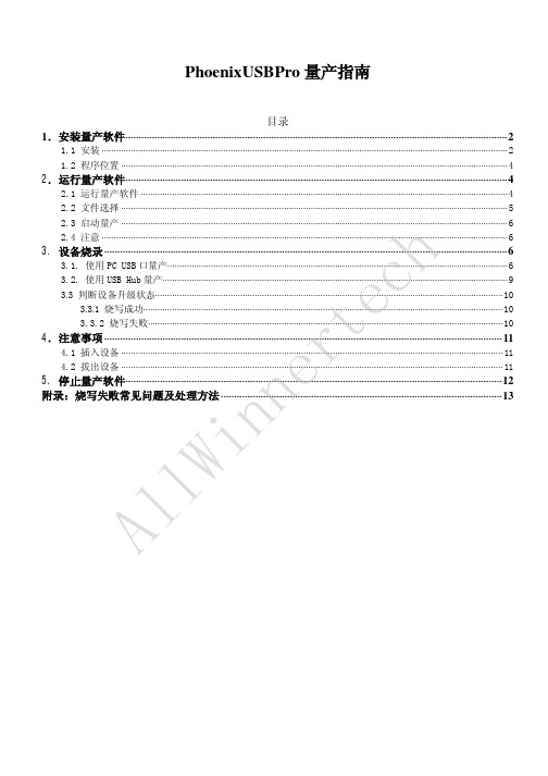
5. 停止量产软件··············································································································································12 附录:烧写失败常见问题及处理方法 ··········································································································13
1.2.1 安装提示界面自动关闭后,打开开始菜单中可以看到
打开
即可启动量产软件。
AllWinnertech 1.2.1 用户也可以在桌面上将看到量产软件图标,如图 1.4 所示。
图 1.4
2.运行量产软件 2.1 运行量产软件
在桌面上打开量产软件
,接下来会出现主界面如下图(图 2.1)所示。
AllWinnertech 2.2 文件选择
AllWinnertech 图3.3
D.量产完成后,出现下图(图 3.4)提示。此时可以拔出标签的 ID 号为 9 的设备。
图 3.4
注意:
1) 只有指示灯为
时才可以插入新设备。
擎泰科技 SK6281 USB PDT量产工具 说明书
Ver. 3.0
3-2-1. UFD Information Setting: USB磁碟參數設定。 (1). Prod. Line: Production Line ID, 客戶可於此設定與記錄產線編號,以方便區別產品是 由哪一條生產線產出的 (2). VID: Vender ID 製造商ID碼。 (3). PID: Product ID 產品ID碼。 (4). Vender Name: 製造商名稱。 (5). Product Name: 產品名稱。 (6). Revision: 產品版別碼。 (7). S/N: 產品序號。 (8). S/N GEN.: 序號產生功能選項。 共有4種測試模式可供選擇: - Fixed S/N num.: 固定式序號。 - Random: 亂數式序號。 - Increase: 遞增式序號。 - Don’t Change SN: 不改變原有序號內容。 (9). Disk Type 磁碟型態。
FAIL
6
2007-12-03
3. 程式介紹:
3-1 主畫面
SK6281 USB Disk 量產工具使用手冊
Ver. 3.0
3-1-1. Time 時間 記錄測試的起始、終止及總共所花費時間
3-1-2. Configuration Selection 選擇設定檔 (Configuration File) 按下下拉選項選擇已經編輯好的Config File. 如欲編輯或修改所選擇的設定檔,可以按下Advanced Button後在Environment Setting畫面 中編輯。Advanced Button的功能將詳述於第3章。
請注意,在還沒輸入Pass Word之前是無法對設定檔進行編輯的,必須輸入正確的Pass word 之後,視窗才會變為可編輯模式。Tool的預設Pass word 為123456 當輸入Password後。 下列章節描述這個設定視窗的各部分功能。 各部分的功能描述如下章節。
NI USB-621x OEM M Series USB-6211 6212 6216 6218 O
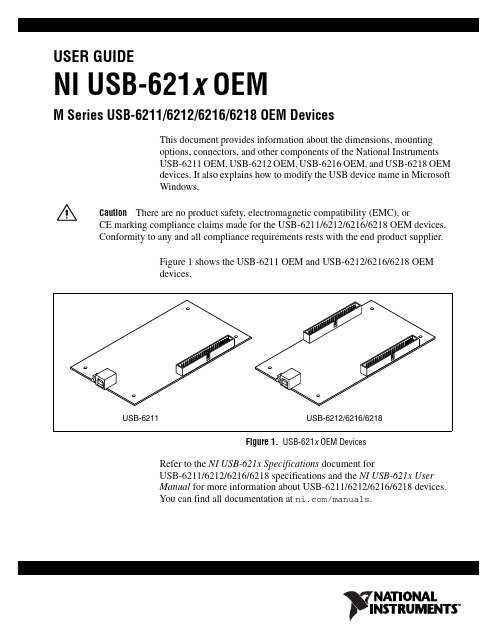
USER GUIDENI USB-621x OEMM Series USB-6211/6212/6216/6218 OEM DevicesThis document provides information about the dimensions, mounting options, connectors, and other components of the National Instruments USB-6211 OEM, USB-6212 OEM, USB-6216 OEM, and USB-6218 OEM devices. It also explains how to modify the USB device name in Microsoft Windows.CautionThere are no product safety, electromagnetic compatibility (EMC), orCE marking compliance claims made for the USB-6211/6212/6216/6218 OEM devices. Conformity to any and all compliance requirements rests with the end product supplier.Figure 1 shows the USB-6211 OEM and USB-6212/6216/6218 OEM devices.Figure 1. USB-621x OEM DevicesRefer to the NI USB-621x Specifications document forUSB-6211/6212/6216/6218 specifications and the NI USB-621x User Manual for more information about USB-6211/6212/6216/6218 devices. You can find all documentation at /manuals.DimensionsFigure2 shows the dimensions of the USB-6211 OEM device.Figure 2. USB-6211 OEM Dimensions in Inches (Millimeters)NI USB-621x OEM User Figure3 shows the dimensions of the USB-6212/6216/6218 OEM device.Figure 3. USB-6212/6216/6218 OEM Dimensions in Inches (Millimeters)© National Instruments Corporation3NI USB-621x OEM User GuideI/O Connector PinoutsRefer to the NI USB-621x User Manual at /manuals for moreinformation about USB-6211/6212/6216/6218 signals and how to connectthem.Figure4 shows the connector pinout on the USB-6211 OEM device.Figure 4. USB-6211 OEM Connector PinoutNI USB-621x OEM User USB-6216 OEM devices.Figure 5. USB-6212/6216 OEM Connector Pinout© National Instruments Corporation5NI USB-621x OEM User GuideNI USB-621x OEM User Guide Figure 6. USB-6218 OEM Connector PinoutNoteIn non-referenced single-ended (NRSE) mode, the USB-6218 OEM device measures AI <0..15> relative to the AI SENSE input, and AI <16..35> relative to AI SENSE 2.© National Instruments Corporation 7NI USB-621x OEM User GuideBoard Mounting the USB-621x OEMThe USB-621x OEM device can be mounted on a motherboard using the 50-pin connector(s) and board mount socket(s), as shown in Figures 7 and 8.NoteYou can use either one or both 50-pin connectors to board mount the USB-6212/6216/6218 OEM device.Figure 7. USB-621x OEM Mounting Using 50-Pin Connectors(USB-6218OEM Device Shown)Figure 8. USB-621x OEM Device Installed on Motherboard(USB-6218OEM Device Shown)Refer to the Device Components section for more information about mounting components.1Mo u nting S t a ndoff 2Bo a rd Mo u nt S ocket350-Pin Connector4US B-6218 OEM Device5Mo u nting ScrewsNI USB-621x OEM User Guide Device ComponentsTable 1 contains information about the components used for interfacing and interacting with the USB-621x OEM device.Modifying the USB Device Name in Microsoft WindowsYou can change how the USB-621x OEM device name appears when users install the device in both the Found New Hardware Wizard that appears when the device is initially installed and in the Windows Device Manager.Windows Vista/XP UsersFigure 9 depicts how a USB-6211 (OEM) device name appears in the Found New Hardware Wizard and Windows Device Manager.Table 1. USB-621x OEM ComponentsComponentReference Designator(s) on PCBManufacturer Manufacturer Part Number 50-pin connector J6*, J73M N2550-6002UB USB connectorJ5AMP 787780-150-pin board mount socket †—3M8550-4500PL (or equivalent)Mounting standoff,using board mount socket —RAF Electronic Hardware M1261-3005-SS ‡ with M3×0.5screw Mounting standoff, using ribbon cable—RAF Electronic Hardware2053-440-SS ** with 4-40 screw* J6 is available on USB-6212/6216/6218 OEM devices only.† You can use either one or both 50-pin connectors to board mount the USB-6212/6216/6218 OEM device.‡ 3/16 in. HEX female-to-female, 14 mm long.** 3/16 in. HEX female-to-female, 1/4 in. long.© National Instruments Corporation 9NI USB-621x OEM User GuideFigure 9. USB-6211 OEM Device in the Found New Hardware Wizardand Device Manager (Windows Vista/XP)To modify the device name in the Found New Hardware Wizard and Windows Device Manager in Microsoft Windows Vista/XP, complete the following steps.NoteYou must have NI-DAQmx 8.6 or later installed on your PC.1.Locate the OEM x .inf file in the y :\WINDOWS\inf\ directory, where x is the random number assigned to the INF file by Windows, and y :\is the root directory where Windows is installed.NoteNew security updates to Microsoft Vista and NI-DAQ 8.6 create random INF files for NI hardware. Windows assigns random file numbers to all INF files, which causes the user to search through several INF files until the correct file is located.If you want to revert back, save a copy of this file as OEM x _original.infin a different location.NI USB-621x OEM User Guide 2.Edit the device INF file by opening OEM x .inf with a text editor. At the bottom of this file are the descriptors where Windows looks to identify the device. Locate the two lines of text that contain in quotes the descriptors for the device name you are modifying. Change the descriptor on both lines to the new device name, as shown in Figure 10.Figure 10. INF File Descriptors Changed to “My Device” (Windows Vista/XP)3.Save and close the INF file.4.Go to the Windows Device Manager.(Windows Vista) In the Device Manager, notice that the OEM device now appears as My Device , as shown in Figure 11.(Windows XP) In the Device Manager, right-click the OEM device underData Acquisition Devices, and select Uninstall . Disconnect the USB cable from your PC.When you reconnect the device, it appears as My Device in the Found New Hardware Wizard and Windows Device Manager, as shown in Figure 11.NoteWhen the device is initially installed, the Windows alert message may display the following: Found New Hardware: M Series USB 621x (OEM). This message appears for a few seconds until the custom name appears and the Found New Hardware Wizard is launched. This alert message device name cannot be changed.Original FileModified File© National Instruments Corporation 11NI USB-621x OEM User GuideFigure 11. “My Device” in the Found New Hardware Wizard and Device Manager(Windows Vista/XP)Note Modifying the INF file will not change the USB-621x OEM device name inMeasurement & Automation Explorer (MAX).NI USB-621x OEM User Guide Windows 2000 UsersFigure 12 depicts how a USB-6211 (OEM) device name appears in theFound New Hardware Wizard and Windows Device Manager.Figure 12. USB-6211 OEM Device in the Found New Hardware Wizardand Device Manager (Windows 2000)To modify the device name in the Found New Hardware Wizard andWindows Device Manager in Windows 2000, complete the following steps.Note You must have NI-DAQmx 8.6 or later installed on your PC.1.Locate the nimioxsu.inf file in the x :\WINNT\inf\ directory,where x :\ is the root directory where Windows is installed.If you want to revert back, save a copy of this file asnimioxsu_original.infin a different location.© National Instruments Corporation 13NI USB-621x OEM User Guide2.Edit the device INF file by opening nimioxsu.inf with a text editor.At the bottom of this file are the descriptors where Windows looks toidentify the device. Locate the two lines of text that contain in quotesthe descriptors for the device name you are modifying. Change thedescriptor on both lines to the new device name, as shown in Figure 13.Figure 13. INF File Descriptors Changed to “My Device” (Windows 2000)3.Save and close the INF file.4.Go to the Windows Device Manager, right-click the OEM device under Data Acquisition Devices, and select Uninstall .5.Disconnect the USB cable from your PC.When you reconnect the device, it appears as My Device in the Found NewHardware Wizard and Windows Device Manager, as shown in Figure 14.NoteWhen the device is initially installed, the Windows alert message may display the following: Found New Hardware: M Series USB 621x (OEM). This message appears for a few seconds until the custom name appears and the Found New Hardware Wizard is launched. This alert message device name cannot be changed.Original FileModified FileNational Instruments, NI, , and LabVIEW are trademarks of National Instruments Corporation. Refer to the Terms of Use section on /legal for more information about NationalInstruments trademarks. Other product and company names mentioned herein are trademarks or trade names of their respective companies. For patents covering National Instruments products, refer to the appropriate location:Help»Patents in your software, the patents.txt file on your CD, or/patents .© 2006–2007 National Instruments Corporation. All rights reserved.372083C-01Oct07Figure 14. “My Device” in the Found New Hardware Wizardand Device Manager (Windows 2000)Note Modifying the INF file will not change the USB-621x OEM device name inMeasurement & Automation Explorer (MAX).。
ni6221采集卡引脚定义
ni6221采集卡引脚定义(原创实用版)目录1.NI 6221 采集卡的概述2.NI 6221 采集卡的主要特点3.NI 6221 采集卡的引脚定义4.NI 6221 采集卡的应用领域正文一、NI 6221 采集卡的概述I 6221 是一款由美国国家仪器(National Instruments)公司推出的数据采集卡,它具有体积小、性能稳定、接口丰富等特点,广泛应用于各种测试、测量和控制系统中。
NI 6221 采集卡支持多种接口标准,如 PCI、PXI、PCI Express 等,用户可以根据自己的需求选择合适的接口类型。
二、NI 6221 采集卡的主要特点1.高性能:NI 6221 采集卡具有高速、高精度的数据采集能力,可以满足各种复杂信号的采集需求。
2.多功能:NI 6221 采集卡支持多种信号输入类型,如模拟信号、数字信号、脉冲信号等,用户可以根据需要进行配置。
3.灵活性:NI 6221 采集卡支持自定义采样率、通道数、数据位等参数,用户可以根据实际需求进行调整。
4.稳定性:NI 6221 采集卡采用高品质元器件,具有优良的抗干扰性能和稳定性,可在恶劣环境下长期稳定工作。
三、NI 6221 采集卡的引脚定义I 6221 采集卡的引脚定义如下:1.Power:电源输入脚,接 +5V 电源。
2.Ground:接地脚,与电源地相连。
3.System Clock:系统时钟输入脚,接系统时钟信号。
4.Trigger:触发输入脚,用于触发数据采集。
5.Channel 0:通道 0 输入脚,接模拟信号输入。
6.Channel 1:通道 1 输入脚,接模拟信号输入。
7.Channel 2:通道 2 输入脚,接模拟信号输入。
8.Channel 3:通道 3 输入脚,接模拟信号输入。
9.Digital I/O:数字输入/输出脚,可配置为输入或输出模式。
10.Counter/Frequency:计数器/频率输入脚,接计数器或频率信号。
Duo v2 NV+ v2 Ultra 2 Ultra 2 Plus Ultra 4 Ultra 4
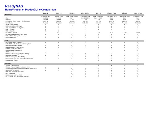
Home/Prosumer Product Line Comparison
Hardware
- CPU - Memory - Embedded flash memory for firmware - Form factor - Serial ATA channels - Hot-swappable disk trays - 10/100/1000 Ethernet ports - USB 2.0 ports - USB 3.0 ports - LCD/OLED display - Compatible with SATA I & II HDD - Native SATA II support - Kensington latch
Volumes
- Volume management
- Volume monitoring and resource view
√
√
- Single-volume auto-expansion (X-RAID/X-RAID2)
√
√
- Journaled file system
√
√
- User and group-level quotas
√ √ √ √ √ √ √ √ √ √ √ √ Optional
√
√ √ √
√ √ √ √
√
√
√ √ √ √ √ √ √
Optional
Ultra 6 Plus
√ √ √ √ √ √ √ √ √ √
√ √ √ √ √ √ √ √ √ √ √ √ Optional
√
√ √ √
√ √ √ √
√
√
√ √ √ √ √ √ √
U盘各主控量产修复工具导航
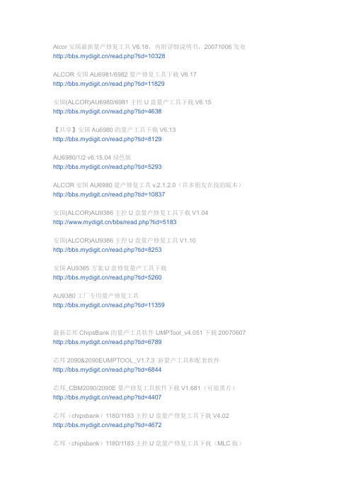
Alcor安国最新量产修复工具V6.18,内附详细说明书,20071006发布/read.php?tid=10328ALCOR安国AU6981/6982量产修复工具下载V6.17/read.php?tid=11829安国(ALCOR)AU6980/6981主控U盘量产工具下载V6.15/read.php?tid=4638【共享】安国Au6980的量产工具下载V6.13/read.php?tid=8129AU6980/1/2 v6.15.04绿色版/read.php?tid=5293ALCOR安国AU6980量产修复工具v.2.1.2.0(许多朋友在找的版本)/read.php?tid=10837安国(ALCOR)AU9386主控U盘量产修复工具下载V1.04/bbs/read.php?tid=5183安国(ALCOR)AU9386主控U盘量产修复工具V1.10/read.php?tid=8253安国AU9385方案U盘修复量产工具下载/read.php?tid=5260AU9380工厂专用量产修复工具/read.php?tid=11359最新芯邦ChipsBank的量产工具软件UMPT ool_v4.051下载20070607 /read.php?tid=6789芯邦2090&2090EUMPTOOL_V1.7.3 新量产工具和配套软件/read.php?tid=6844芯邦_CBM2090/2090E量产修复工具软件下载V1.681(可做黑片)/read.php?tid=4407芯邦(chipsbank)1180/1183主控U盘量产修复工具下载V4.02 /read.php?tid=4672芯邦(chipsbank)1180/1183主控U盘量产修复工具下载(MLC版)/read.php?tid=4673芯邦CBM2080主控U盘量产修复工具下载V4.0/bbs/read.php?tid=5808iCreate5122方案U盘量产工具下载V1.06/read.php?tid=4335iCreate 5122方案U盘量产修复工具下载V1.08/read.php?tid=4333iCreate 5062LQ主控U盘量产工具下载/read.php?tid=4324iCreate i5128量产修复工具PDx16 V1.3B1最新版下载/read.php?tid=11758icreate 5128l 量产工具程序下载V1.18/read.php?tid=6002iCreate5128主控量产工具1.17b/read.php?tid=5767iCreate5128 方案U盘量产工具下载V1.08/read.php?tid=4319iCreate5128主控量产工具扩充特别版2007/read.php?tid=4318iCreate5122/5128方案U盘量产修复工具PDx16最新版V1.14B3,感谢wyggang提供/read.php?tid=4735iCreate i5062方案U盘修复量产工具中文版V3.27/read.php?tid=5263iCreate i5062方案U盘修复量产工具下载V3.20/read.php?tid=5262iCreate 5060/5062-ZD主控U盘量产工具下载V2.20(适合早期U盘)/read.php?tid=6109iCreate 5062主控U盘量产修复工具下载V3.38/read.php?tid=6299iCreate i5068主控量产检测工具下载V3.11/read.php?tid=5261UT163 U盘量产修复工具下载USBest(MP tool)/read.php?tid=4239Ut163方案U盘量产修复工具下载V3.0.1.14/read.php?tid=8505Ut161方案U盘量产修复工具下载V1.3.3/read.php?tid=5330SM321&SM323 U盘量产修复工具下载/read.php?tid=3970SMI32X主控U盘量产修复程序下载/bbs/read.php?tid=5811MP2202方案U盘修复工具下载V1.032/read.php?tid=4322U盘X2202方案修复工具下载V1.33/read.php?tid=5214ARK3143主控U盘量产修复工具软件V1.3/read.php?tid=4344SKY6201 U盘量产修复工具下载/read.php?tid=4317OTI2168&6828方案U盘量产修复工具V2.855/bbs/read.php?tid=5184OTI6808 主控U盘量产修复工具下载V1.30(附FLASH清空程序)/bbs/read.php?tid=5812NC1116方案U盘修复量产工具下载V1.00/read.php?tid=5259NC1119方案U盘修复量产工具下载/read.php?tid=5258skymedi量产修复工具-适合kingston data traveler DT1/read.php?tid=9286朗科NT2033CMS主控量产工具/read.php?tid=4784朗科NT2033BMS 量产工具v2.0A/read.php?tid=4921朗科2033CMS扩容工具/read.php?tid=5053朗科NT2033CMS主控Flash清空工具/read.php?tid=4785朗科nt2033cms量产工具20070706(1.0.2.20)新/read.php?tid=6980群联phison 2143-2134系列U盘量产格式化修复程序下载V1.28/bbs/read.php?tid=5806群联phison UP8-R 主控U盘量产格式化工具下载V2.0/bbs/read.php?tid=5800phison UP10主控U盘量产修复工具下载v1.78,感谢zhby9462提供/read.php?tid=6984TRVMPION T3551的U盘量产修复工具下载(可修清华普天的U盘)/read.php?tid=9689UDK2008主控方案资料说明/支持FLASH列表/量产修复工具下载(在二楼) /read.php?tid=3434上传一个很少见的U盘量产工具AB8028主控V1.01/read.php?tid=6278爱国者迷你王II代(极速型)U盘格式化工具下载V2.0/read.php?tid=6614aigo智慧棒85倍速格式化工具/read.php?tid=8270最新超强U盘方案上市了&AMECO MW6208量产修复工具下载/read.php?tid=6365MW6208方案U盘量产修复工具V2.0&FLASH支持列表下载[目前最新20070730] /read.php?tid=6756MW6208方案U盘量产修复工具V2.0下载[20070818]/read.php?tid=7499M5634主控U盘量产修复工具下载V2.1/read.php?tid=7919贴一个台电U盘的修复工具/read.php?tid=9145ARK方案U盘格式化修复工具V1.4版/bbs/read.php?tid=11839U盘存储相关工具:检测U盘是否被扩容的工具:UWriteTest/read.php?tid=7853比ATTO更好的U盘测速软件HDBENCH/read.php?tid=7477SDFormatter V2.0下载(Panasonic SD卡格式化软件)/read.php?tid=8182可以解决无法格式化的HP U盘格式化工具/read.php?tid=10217MMC卡修复软件-MMCmedic格式化工具下载/bbs/read.php?tid=5392存储卡修复软件下载,可修复MMC SD XD CF卡等/bbs/read.php?tid=5391台电系列U盘格式化修复工具Urescue V1.024/read.php?tid=11021AU6368主控多合一读卡器故障图解&驱动低格工具下载/read.php?tid=6292芯邦CBM3080SD卡MMC卡量产工具及相关资料_用读卡器就可以做/read.php?tid=8646慧荣SMI方案SM321量产工具Test_SM32x_H0229(汉化版)/thread-24066-1-2.htmlSM321最新版本1.7量产工具/thread-25016-1-4.htmlSM321与SM323量产工具下载/thread-6948-1-4.html慧荣SMI_U盘量产工具合集/thread-29111-1-4.html飙王U盘修复工具321TestTool0608/thread-17043-1-5.html慧荣SMI方案2008年首版SMI H0109量产工具及FLASH支持列表/thread-22763-1-9.htmlSM32x_E0824量产工具/thread-19918-1-12.htmlSM321&SM323量产工具/thread-14217-1-16.html纽曼闪盘USB2.0(321)/thread-7293-1-17.htmlSMI32X主控U盘量产修复程序下载/thread-6949-1-18.html群联Phison方案phison-UP10v1.78.00金士顿u盘量产工具/thread-17796-1-2.htmlKingston_1G_phison-UP10量产工具/thread-13351-1-5.htmlPhison MPTool MP2232 v1.06.00/thread-25360-1-7.htmlphison UP10主控U盘量产修复工具下载v1.78/thread-6967-1-8.htmlPHISON UP12(PS2231) &UP10(PS2136)量产工具V1.890/thread-20756-1-11.html群联phison 2143-2134系列U盘量产格式化修复程序下载V1.28 /thread-6965-1-13.html群联phison2143-2134修复程序/thread-9190-1-17.html纽曼闪盘USB2.0(2134)/thread-7296-1-17.html群联phison UP8-R 主控U盘量产格式化工具下载V2.0/thread-6966-1-17.html联盛USBest方案联盛USBest-UT165量产工具汉化及说明/thread-18453-1-1.html台电U盘格式化量产工具UT163 setup-v3.7.4.0/thread-9498-1-2.htmlut165量产工具1.65.13.4/thread-21240-1-6.htmlubest163/165通用量产工具,兼容性暴强!/thread-25211-1-7.htmlUSBest UT190 v.1.90.7.0/thread-25660-1-7.htmlUT163 U盘量产修复工具下载USBest(MP tool)/thread-6945-1-8.htmlUt161方案U盘量产修复工具下载V1.3.3/thread-6947-1-11.html纽曼闪盘USB2.0(UT161)/thread-7297-1-17.htmlUt163方案U盘量产修复工具下载V3.0.1.14/thread-6946-1-18.html擎泰Skymedi方案SK6211_20090227_BA/thread-30820-1-3.htmlsk6211主控U盘量产修复工具/thread-11682-1-3.htmlSK6281量产工具/thread-10671-1-11.htmlSK6211_20071207更新/thread-19275-1-13.htmlSK6281量产工具20080123/thread-12139-1-16.htmlSKY6201U盘量产修复工具/thread-13615-1-16.html安国(群胜)Alcor方案安国AU6981 AU6982 AU6983 AU6984 AU6986 最新量产工具20081010 /thread-31700-1-1.html安国AU6983/AU6986最新量产工具( V080630)/thread-19295-1-1.htmlAlcorMP(090227)/thread-30182-1-1.html安国最新6983,6986量产工具MP(09010902)/thread-30979-1-2.html安国Au6980的量产工具下载V6.13ALCOR安国AU6980量产修复工具v.2.1.2.0/thread-11591-1-4.htmlAU9384量产修复工具MP2.01 中文版/thread-29151-1-4.html安国AlcorMP量产工具08082902版本/thread-27183-1-6.html安国Alcor MP UFD Version : 08.12.08/thread-25447-1-7.html安国AU6980-6982v6.13/thread-23535-1-8.html安国量产工具中英繁三语AlcorMP(08.02.28)版/thread-22762-1-9.html6980安国U盘单机生产工具适用于6980 6981 6982 6983/thread-22723-1-9.html安国(ALCOR)AU6980/6981主控U盘量产工具下载V6.15/thread-6907-1-9.html安国6980/6982量产工具6.13/thread-19367-1-10.htmlAU6980/1/2 v6.15.04绿色版/thread-6909-1-11.html安国AU9385方案U盘修复量产工具下载/thread-6912-1-12.htmlAU6981、6982、6983 量产修复工具v6.21工具下载/thread-19410-1-12.htmlAU9386P主控U盘修复工具/thread-19016-1-13.html安国(ALCOR)AU9386主控U盘量产修复工具V1.10/thread-6911-1-14.htmlAU9386修复/thread-11972-1-16.html安国(ALCOR)AU9386主控U盘量产工具下载V1.04/thread-6910-1-18.html芯邦Chipsbank方案芯邦CBM2090E2091最新版量产工具V1.8.3.2(支持黑片及downgrade) /thread-13745-1-2.html芯邦chipsbank 1180/1183主控U盘量产修复工具下载V4.02/thread-6921-1-2.html芯邦ChipsBnk专修工具适合大容量的umptoolv4.02mlc专用/thread-8293-1-3.html芯邦CBM2091最新量产修复工具V1.80/thread-16180-1-3.html芯邦2090&2090E-UMPTOOL_V1.7.3 新量产工具和配套软件芯邦CBM2080主控U盘量产修复工具下载V4.0/thread-6924-1-3.html芯邦CBM3082 MP Tool Version :2.0.15/thread-26619-1-5.htmlCBM209XUMPToolV1.9.15_A30319/thread-22772-1-5.html芯邦2092最新量产工具CBM209X_UMPTOOL_V1.9.21_Beta_0826 /thread-20642-1-5.html芯邦CBM2092 UMPTool V2.0.0 只支持主控2092了,不再支持2091 /thread-25144-1-6.html芯邦CMB1180 Umptool Version : 4.02 MLC/thread-26409-1-6.html芯邦cbm2080量产工具V4.1专用FLASH/thread-22774-1-7.html芯邦CBM3080量产修复工具V1.25(百立SD卡)/thread-16181-1-7.html芯邦CBM1183的量产工具/thread-19920-1-8.html芯邦2091A3版主控50NM新制程FLASH最新量产工具/thread-24261-1-8.html芯邦-cbm2072量产工具V1.0 可做广告盘/thread-22773-1-8.html芯邦(chipsbank)11801183主控U盘量产修复工具下载(MLC版) /thread-16183-1-9.html芯邦2091MPTool_V1.9.13_8bitECC0314/thread-22771-1-9.html芯邦2091A3版主控50NM新制程FLASH最新量产工具/thread-22770-1-9.htmlMT29F8G08MAA v3专用的CBM2080工具V4.1/thread-16179-1-10.html芯邦ChipsBank的量产工具软件UMPTool_v4.051下载20070607 /thread-6917-1-11.htmlCBM3080_SD卡量产工具v1.262/thread-16178-1-12.html芯邦_CBM2090/2090E量产修复工具软件下载V1.681/thread-6919-1-12.htmlCBM2090CBM2091量产工具/thread-19917-1-12.html芯邦CBM209XUMPToolV1.9.15_A30402/thread-19334-1-13.html芯邦CBM2090和2090E量产工具V1.6.8.1普通版/thread-19333-1-13.html芯邦CBM209XUmptool_V1[1].9.5_1227芯邦量产工具CBM2091_1.9.13_A3版主控(50纳米技术闪存)/thread-16182-1-14.htmlCBM209X_UMPToolV1.9.15_A30319/thread-16177-1-14.htmlCBM2091A3版通用量产工具080319/thread-16176-1-14.htmlCBM2080量产工具V4.05 MLC专用版/thread-16175-1-15.htmlCBM2090E_CBM2091分区加密工具/thread-16173-1-15.htmlCBM2076主控(指纹U盘)量产修复工具v3.18/thread-16172-1-15.htmlCBM2076+SW6888指纹U盘量产工具V3.20/thread-16171-1-15.htmlcbm2072量产工具V1.0_可做网页广告盘/thread-16170-1-15.html芯邦2090E量产/thread-14556-1-15.htmlCBM2090UMPTOOLV1.5.18普通版/thread-14562-1-16.html纽曼闪盘USB2.0(2080)/thread-7294-1-17.html时代民芯MXTronics方案超科微Ameco方案MW6208E_8208量产工具_1.0.5.0_20081201/thread-24407-1-1.htmlMXT6208A +8208量产工具再次更新!!UdTools1.0.3.8_200806120 /thread-18635-1-2.htmlMW6208E_82088209量产工具_1.2.0.520 20090415/thread-31201-1-2.html迈科微(MW6208A 6208E 8208量产软件UdTools1.0.4/thread-24470-1-2.htmlMW6208E 8208量产工具1.2.0.3 20090306 正式版/thread-29611-1-2.html金士顿MW6208E_8208量产工具_1[1].2.0.2beta_20090302/thread-30708-1-3.htmlMXT6208A +MXT6208e+8208量产工具更新!!UdTools1.0.4.5_20080910 /thread-21619-1-4.html迈科微优盘(MW6208E_8208芯片)量产工具/thread-25312-1-4.htmlU盘量产工具MXT6208和MXT6208+A MPTool v1.0.2.9_20080325 /thread-16192-1-4.htmlMW6208E 8208 1.0.5.0解决4G闪存量产后成2G问题/thread-24418-1-4.htmlMW8209产量工具/thread-29158-1-4.html最新超强U盘方案&AMECO MW6208量产工具/thread-17877-1-5.htmlMW6208E 8208 1.0.4.9支持现代H27U(A)BG8U5MTR两种新闪存/thread-24415-1-8.htmlMW6208方案U盘量产修复工具V2.0与FLASH支持列表下载[目前最新20070730] /thread-6973-1-10.htmlMXT6208A量产工具/thread-20869-1-11.htmlmxt6208A+MW6208通用驱动/thread-12206-1-11.htmlMW6208方案U盘量产修复工具V2.0下载[20070818]/thread-6974-1-12.htmlMXT6208量产工具/thread-19659-1-12.htmlAMECO MW6208量产修复工具下载(版本更新)/thread-6972-1-17.html朗科Netac方案朗科NT2033CMS主控量产工具/thread-6958-1-1.html朗科U180 NT2039 量产工具/thread-23868-1-1.html朗科NT2033CMS主控Flash清空工具/thread-6961-1-2.html朗科NT2033BMS 量产工具v2.0A/thread-6959-1-2.html分享:朗科NT2033BMS 量产工具v2.0A/thread-10246-1-2.htmlNetac U219 NT2039/thread-25754-1-3.html朗科U208量产套餐/thread-19509-1-4.htmlNetac NT2033BMS Version 2.0A/thread-25755-1-7.html朗科U盘量产工具1.0.8.4破解版/thread-13346-1-7.html朗科优芯系列通用格式化修复量产工具/thread-25209-1-7.html朗科u320(NT2033BMS)量产工具/thread-20993-1-8.html朗科NT2033BMS2.0/thread-22551-1-9.html朗科nt2033cms量产工具20070706(1.0.2.20)/thread-6962-1-17.html朗科2033CMS扩容工具下载/thread-6960-1-17.html我想iCreate方案iCreate 5062主控U盘量产修复工具下载V3.38/thread-6943-1-3.htmli5128量产修复工具PDX16 v1.34/thread-15753-1-5.html5128a量产新版/thread-14568-1-11.htmliCreate i5062-ZD方案U盘修复量产工具下载V3.20/thread-6941-1-5.html台晶T5188(我想i5188)扩容升级工具v1.0/thread-25741-1-7.htmliCreate i5188量产工具PDx16 v1.5B5/thread-25740-1-7.html台晶T5188新版量产工具PDx16 v1.51(原iCreate5188)/thread-25739-1-7.html5128 量产工具最新版1G 2G V1.14B3/thread-18484-1-7.htmliCreate5122/5128方案U盘量产修复工具PDx16最新版V1.14B3 /thread-6938-1-8.htmliCreate i5062-ZD修复量产工具V3.161/thread-24518-1-8.htmliCreate U盘芯片通用修复工具/thread-3778-1-8.htmliCreate5128 方案U盘量产工具下载V1.08/thread-6934-1-9.htmli5128最新量产工具扩充版V1.08B3/thread-22927-1-9.html5128 5127升级工具ut专用/thread-22549-1-10.html5128至尊版量产工具/thread-22325-1-10.html5128 PDx16_V1.34/thread-22168-1-10.htmliCreate PDx16 V1.14B3 适用于5062LQ、5122、5128等主控芯片/thread-11810-1-10.htmlU盘i5062_datasheet/thread-2053-1-10.htmliCreate5128主控量产工具1.17b/thread-6932-1-11.htmliCreate i5068主控量产检测工具下载V3.11/thread-6944-1-11.htmliCreate U盘芯片通用修复工具(中文版)/thread-18285-1-11.htmliCreate i5127/thread-14567-1-12.htmli5128/5122/5062LQ量产工具(最新版)/thread-19411-1-13.htmlIC5128量产程式1.3b版/thread-18485-1-13.htmliCreate U盘芯片通用修复工具(中文版)/thread-15850-1-15.htmliCreate i5062ZD方案U盘修复量产工具中文版V3.27/thread-6939-1-15.htmlicreate5026-LQ v1.18量产工具/thread-14999-1-15.htmlU盘工具5128PD V1.16/thread-13549-1-16.html5128 1.14 5128 1.18板量产工具/thread-9258-1-17.htmliCreate 5060/5062-ZD主控U盘量产工具下载V2.20/thread-6942-1-18.htmlicreate 5128l 量产程序1.18/thread-6931-1-18.htmliCreate 5062LQ 方案U盘量产工具,注意不是5062ZD 5122的升级版,支持软升级/thread-6929-1-18.htmliCreate 5122 方案U盘工具下载V1.08/thread-6927-1-18.htmliCreate5122方案U盘量产工具下载V1.06/thread-6926-1-18.htmliCreate U盘芯片通用修复工具(中文版)/thread-3984-1-18.html鑫创3S(Solid State System)方案SSS-6690,SSS-6677,SSS-5521方案的优盘工具/thread-31372-1-1.htmlSSS6677 B5最新量产修复工具中文汉化版/thread-22761-1-3.html台湾U盘方案SSS 6677 B5,最新量产工具,不要钱的啊/thread-17269-1-3.htmlSSS6677开卡量产工具V2103版本,台湾鑫创大陆总代理镇深科技提供版本/thread-22094-1-3.html最新的3S_USB_V3.010-UltraNet量产工具/thread-27530-1-3.html3SU盘量产工具套餐/thread-29116-1-4.html3S SSS6686 Version :2.112/thread-25345-1-7.htmlSSS 6666B1主控U盘量产修复工具V1.51/thread-9188-1-10.html台湾U盘方案SSS 6677 B5,最新量产工具,支持Intel 8GB芯片,速度超快!/thread-14326-1-11.html瀚邦OTI方案OTI 2168&6828方案U盘量产工具PTMD2.9.0.11/thread-29110-1-4.htmlOTI OTI2168&6828 PTMD Vesion :2.9.0.11D/thread-25834-1-7.html[瀚邦OTI方案]OTI 2126主控芯片多合一读卡器量产工具及资料/thread-23328-1-9.html[瀚邦OTI方案]OTI 1905 sd卡量产修复工具V1.05/thread-23327-1-9.html[瀚邦OTI方案]OTI 1901 MMC卡量产修复工具/thread-23326-1-9.html[瀚邦OTI方案]OTI6808 主控U盘量产修复工具下载V1.30(附FLASH清空程序)/thread-23325-1-9.html[瀚邦OTI方案]OTI2168&6828方案U盘量产修复工具V2.855/thread-23324-1-9.htmlOTI2168&6828方案U盘量产工具PTMD2.9.0.11D/thread-22764-1-9.htmlOTI2168与6828方案U盘量产修复工具V2.855/thread-6954-1-12.htmlOTI6808 主控U盘量产修复工具下载V1.30(附FLASH清空程序)/thread-6955-1-12.htmlOTI 6828修复工具/thread-12897-1-16.html其它U盘方案经典极少的U盘产量工具CION 192 192EF/thread-29004-1-2.htmlSUNPLUS的刷新工具/thread-2554-1-4.html金士顿DTI 2G U盘修复工具/thread-17245-1-4.html台湾邑福(efortune)eu201量产工具20090107/thread-29161-1-4.htmlProlific_PL-2528_MPTool_CM_M2209/thread-26574-1-5.htmlHP优盘格式化工具HPUSBFW+2.20/thread-27914-1-5.htmlX2202 Mass Production Tool Version : 1.33/thread-25924-1-6.htmlDDTIC-DT1628-L量产工具/thread-14561-1-8.htmlU盘2202修复工具/thread-3986-1-8.htmlU盘PP2201修复工具/thread-2549-1-8.htmlCCM3110芯片,U盘修复工具/thread-22918-1-9.html爱国者迷你王II代(极速型)U盘格式化工具下载V2.0/thread-6970-1-9.htmlUDK2008方案U盘量产修复工具HSMPTool V1.0D/thread-9191-1-11.htmlM5634主控U盘量产修复工具下载V2.1/thread-6975-1-13.htmlAB8028_U盘量产工具/thread-14267-1-16.htmlU盘pp2366修复工具/thread-3300-1-17.htmlmp2202主控工具/thread-7187-1-17.htmlU盘量产工具AB8028主控V1.01/thread-6969-1-17.htmlUDK2008主控方案资料说明/支持FLASH列表/量产修复工具下载/thread-6968-1-17.htmlMP2202方案U盘修复工具下载V1.032/thread-6950-1-17.htmlNC1119方案U盘修复量产工具下载/thread-6957-1-17.htmlNC1116方案U盘修复量产工具下载V1.00/thread-6956-1-17.htmlARK3143主控U盘量产修复工具软件V1.3/thread-6952-1-17.htmlU盘X2202方案修复工具下载V1.33/thread-6951-1-17.htmlNC1119U盘修复工具/thread-3983-1-18.html。
u盘芯片组对应表
/read.php?tid=144332
鑫创(3S)
SSS6677 第二次量产ISO镜像成功(同一U盘)
/read.php?tid=51867
SSS6677量产USB-CDROM方法(数码之家首发)
成功量产金士顿 2G DataTraveler Mini U盘
/read.php?tid=32256
金士顿DataTraveler100 8G 量产教程,还有附加技巧哦【原创】
/read.php?tid=19718
初学者金士顿逸盘4G量化成功初体验 [SK6211_20080402_BA]
/read.php?tid=44864
一波三折 金士顿4G 量产真正成功了(具体步骤)速度也大大提升 [SK6281]
/read.php?tid=40652
/read.php?tid=19222
台电U盘,慧荣324BC主控量产成功,重发祥细说明
/read.php?tid=38384
一看就会,smi SM32x量产详细图示教程(已添加说明文字)
/read.php?tid=46874
群联UP14方案4G金士顿U盘量产过程,新手看看,高手止步
/read.php?tid=61387
金士顿8G 量产CDROM成功,芯片型号:SSS 6677/SK6281/PS2232
/read.php?tid=58925
kingston 4G量产CDROM和分区成功历程(心得)还有教程 [PS2231]
/read.php?tid=52110
金士顿4GU盘量产(失败,情况糟糕!)经历28小时终于修复(过程附上) [PS2232]
/read.php?tid=51452
NI USB-7856R OEM 用户手册说明书
USER MANUALNI USB-7856R OEMR Series for USB Multifunction RIO with Kintex-7 160T FPGA Français Deutsch日本語한국어简体中文/manualsThis document provides dimensions, connectivity information, and pinouts for the National Instruments USB-7856R OEM device.Caution National Instruments makes no product safety, electromagneticcompatibility (EMC), or CE marking compliance claims for NI USB-7856R OEMdevice. The end-product supplier is responsible for conformity to any and allcompliance requirements.Caution Do not operate the NI USB-7856R OEM device in a manner notspecified in this user manual. Product misuse can result in a hazard. You cancompromise the safety protection built into the product if the product is damaged inany way. If the product is damaged, return it to National Instruments for repair.Hardware OverviewThe following high-level block diagram represents the NI USB-7856R OEM device.Figure 1. NI USB-7856R OEM Device Block DiagramUSBC O N N E C T O R 1C O N N E C T O R 2C O N N E C T O R 3C O N N E C T O R 02 | NI USB-7856R OEM User Manual | Parts LocatorB Connector2.Power Supply Connector3.Power Switch4.External LED Attachments5.Connector 0 (Analog)6.Connector 1 (Digital)7.Connector 2 (Digital)8.Connector 3 (Digital)NI USB-7856R OEM Device ComponentsThe following table lists the interfacing components on the NI USB-7856R OEM device and the component manufacturers.The following table lists and describes the I/O connectors on the NI USB-7856R OEM device. Refer to the connector manufacturer for information about using and matching these connectors.NI USB-7856R OEM User Manual | © National Instruments | 34 | NI USB-7856R OEM User Manual | Dimensions2X .175 (4.45)2X 2.863 (72.72)2X 6.055 (153.81)6.263 (159.08)2X 6.675 (169.55).119 (3.02).000 (0)2X 6.435 (163.46)3X .285 (7.24)3X 6.115 (155.32)6.400 (162.56)2.055 (52.19)3.797 (96.44)2X 5.838 (148.29).000 (0)0.285 (7.24)NI USB-7856R OEM User Manual | © National Instruments | 5Note Visit /dimensions for more information about the dimensions ofthe NI USB-7856R OEM device, including two-dimensional drawings and three-dimensional models.Note The NI USB-7856R OEM device has plated mounting holes that can act aschassis ground.Connecting the NI USB-7856R OEM DeviceThe NI USB-7856R OEM device provides connections for eight analog input (AI) channels, eight analog output (AO) channels, and forty-eight digital input/output (DIO) channels, as shown in Figure 2.6 | NI USB-7856R OEM User Manual | Figure 2. NI USB-7856R OEM Device PinoutAnalog InputThe NI USB-7856R OEM device provides connections for eight AI channels. Each channel has an AI+ pin, AI- pin, and AIGND pin to which you can connect both single-ended or differential voltage signals. Use the AISENSE pin to connect non-referenced single-ended signals.Connecting Single-Ended Voltage SignalsTo connect referenced single-ended voltage signals to the NI USB-7856R OEM device, you must connect the voltage ground signal to AI GND in order to keep the common-mode voltage in the specified range, as shown in Figure 3.Figure 3. Connecting Referenced Single-Ended Signals to the NI USB-7856R OEM DeviceV NI USB-7856R OEM User Manual | © National Instruments | 7To connect non-referenced single-ended voltage signals to the NI USB-7856R OEM device, you must connect the voltage ground signal to AI SENSE in order to keep the common-mode voltage in the specified range, as shown in Figure 4.Figure 4. Connecting Non-Referenced Single-Ended Signals to the NI USB-7856R OEM DeviceVConnecting Differential Voltage SignalsYou can connect grounded or floating differential signal sources to the NI USB-7856R OEM device. Connect the positive voltage signal to the AI+ and the negative voltage signal to AI-. To connect grounded differential signals to the NI USB-7856R OEM device, you must also connect the signal reference to AI GND.Figure 5. Connecting Grounded Differential Signals to the NI USB-7856R OEM DeviceVTo connect floating differential signals to the NI USB-7856R OEM device, you must connect the negative and positive signals to AI GND through 1 MΩ resistors to keep the voltage within the common-mode voltage range. If the voltage source is outside the common-mode voltage range, the NI USB-7856R OEM device does not read data accurately.8 | NI USB-7856R OEM User Manual | Figure 6. Connecting Floating Differential Signals to the NI USB-7856R OEM DeviceV Analog OutputThe NI USB-7856R OEM device provides connections for eight analog output channels. Each channel has an AO pin and AOGND pin to which you can connect a load.Figure 7. Connecting a LoadLOADDigital I/OThe NI USB-7856R OEM device provides connections for 48 digital input/output (DIO)channels. Connector 1, Connector 2, and Connector 3 contains 16 low-speed channels that can run up to 10 MHz signal frequencies. Each connector has selectable logic levels that you can configure as 1.2 V, 1.5 V, 1.8 V, 2.5 V, or 3.3 V. You can configure each channel as input or output.NI USB-7856R OEM User Manual | © National Instruments | 9Figure 8. Connecting to the DIO Channels1.Low-speed signal frequencies up to 10 MHz with logic levels configured as 1.2 V, 1.5 V, 1.8 V,2.5 V, or3.3 V. Connectors 1 and 2 share the same voltage settings.2.LEDThe DIO channels connect to the FPGA through buffers, which have overvoltage and undervoltage protection as well as over current protection. Refer to theNI USB-7856R OEM device Specifications for more information about the maximum voltage and current.When the system powers on, the DIO channels are set as input low with pull-down resistors.To set another power-on state, you can configure the NI USB-7856R OEM device to load a VI when the system powers on. The VI can then set the DIO lines to any power-on state.National Instruments recommends performing signal integrity measurements to test the effect of signal routing with the cable and connection accessory for your application.LEDsIf you are putting the NI USB-7856R OEM device in an enclosure, you can either seat the optional lightpipes on the device or attach external LEDs, as described in the Attaching External LEDs section. When the lightpipes are attached, the top row is Error, USB Ready,and POWER LEDs, and the bottom row has the User LEDs.The NI USB-7856R OEM device has six LEDs which reflect the device state.10 | NI USB-7856R OEM User Manual | NI USB-7856R OEM User Manual | © National Instruments | 11Figure 10. Attaching External LEDsLEDExternalResistorPower SwitchUse the power switch to power the NI USB-7856R OEM device on and off. The following figure shows the pins on the power switch and power circuitry.Figure 11. Power Switch (Shown in the On Position)Device The following table lists the pin locations and signal descriptions.12 | NI USB-7856R OEM User Manual | +5 V Power SourceUse the +5 V terminals on the I/O connector supply +5 V referenced to DGND to power external circuitry.Caution Never connect the +5 V power terminals to analog or digital ground orany other voltage source on the NI USB-7856R OEM device or any other device.Doing so can damage the device and the computer. National Instruments is not liablefor damage resulting from such a connection.The power rating is 4.75 to 5.1 VDC at 0.5 A.Autonomous ModeYou can run the NI USB-7856R OEM device without a USB connection to a host computer using Autonomous Mode. To collect data the NI USB-7856R OEM device acquires in Autonomous Mode, you must reconnect the NI USB-7856R OEM device to a host computer.Caution Data is lost and is not recoverable upon reconnection if a DMA FIFOoverflows while the NI USB-7856R OEM device is disconnected from the hostcomputer or if the NI USB-7856R OEM device loses power at any point. Autonomous Mode includes the following capabilities.NI USB-7856R OEM User Manual | © National Instruments | 13Worldwide Support and ServicesThe National Instruments website is your complete resource for technical support. At / support you have access to everything from troubleshooting and application development self-help resources to email and phone assistance from NI Application Engineers.Visit /services for NI Factory Installation Services, repairs, extended warranty, and other services.Visit /register to register your National Instruments product. Product registration facilitates technical support and ensures that you receive important information updates from NI.National Instruments corporate headquarters is located at 11500 North Mopac Expressway, Austin, Texas, 78759-3504. National Instruments also has offices located around the world. For telephone support in the United States, create your service request at /support or 1The Host VI errors out if you do not call the Close FPGA VI Reference Function without aborting or resetting the FPGA VI.14 | NI USB-7856R OEM User Manual | dial 512 795 8248. For telephone support outside the United States, visit the Worldwide Offices section of /niglobal to access the branch office websites, which provide up-to-date contact information, support phone numbers, email addresses, and current events.NI USB-7856R OEM User Manual | © National Instruments | 15Refer to the NI Trademarks and Logo Guidelines at /trademarks for information on National Instruments trademarks. Other product and company names mentioned herein are trademarks or trade names of their respective companies. For patents covering National Instruments products/technology, refer to the appropriate location: Help»Patents in your software, the patents.txt file on your media, or the National Instruments Patent Notice at /patents. You can find information about end-user license agreements (EULAs) and third-party legal notices in the readme file for your NI product. Refer to the ExportCompliance Information at /legal/export-compliance for the National Instruments global trade compliance policy and how to obtain relevant HTS codes, ECCNs, and other import/export data.© 2013 National Instruments. All rights reserved.374230A-01Nov13。
National Instruments USB-6000 OEM设备参考指南说明书
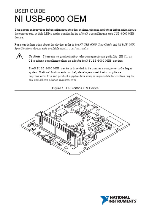
USER GUIDENI USB-6000 OEMThis document provides information about the dimensions, pinouts, and other information about the connectors, switch, LEDs, and mounting holes of the National Instruments USB-6000 OEM device.For more information about the device, refer to the NI USB-6000 User Guide and NI USB-6000 Specifications documents available at /manuals.Caution There are no product safety, electromagnetic compatibility (EMC), orCE marking compliance claims made for the NI USB-6000 OEM devices.The NI USB-6000 OEM device is intended to be used as a component of a largersystem. National Instruments can help developers meet their compliancerequirements. The end product supplier, however, is responsible for conforming toany and all compliance requirements.Figure 1. USB-6000 OEM DeviceUSB-6000 OEM Device SpecificationsMost specifications of the USB-6000 OEM device are listed in the NI USB-6000 Specifications document on /manuals. The following sections contain exceptions to the main specifications.Physical Characteristics Weight...............................................................23 g (0.811 oz) Dimensions.......................................................693 mm × 658 mm × 117 mm(2.73 in. × 2.59 in. × 0.46 in.)Figure 2. USB-6000 OEM Device Dimensions in Inches (Millimeters)2||NI USB-6000 OEM User GuideI/O Connector PinoutsFigure3 shows the USB-6000 OEM device I/O connector pinouts.Figure 3. USB-6000 OEM Terminal AssignmentsSignal DescriptionsMost of the signals available on the I/O connector are described in the NI USB-6000 User Guide document available for download at /manuals. Table1 describes additional signals on the I/O connector of the OEM device.Table 1. Additional Signal DescriptionsSignal Name Reference Direction Description VBUS D GND Input USB PowerD+, D- D GND Input/Output USB Data LinesLED D GND Output Status LED DriverFor more information about USB signals, refer to the Universal Serial Bus Specification accessible at .NI USB-6000 OEM User Guide|© National Instruments|34| |NI USB-6000 OEM User GuideUsing the 34-Pin Connector with a Board Mount SocketThe USB-6000 OEM device can be mounted to a motherboard using the 34-pin connector, as shown in Figures 4 and 5.Figure 4. Mounting Using a 34-Pin ConnectorNoteRefer to the Device Components section for more information aboutmounting components.Figure 5. USB Device Installed on Motherboard1Board Mount Socket 234-Pin Connector3USB-6000 OEM Device4Mounting Screw 5Mounting StandoffConnecting to USBYou can use the USB connector on the USB-6000 OEM device to connect to the USB host. In this case, leave the D+ and D- signals (on the 34-pin connector) and VBUS unconnected.You can also use a USB connector on your motherboard to connect the USB-6000 OEM device to the USB host through the 34-pin connector. In this case, do not connect to the USB connector on the USB-6000 OEM device.Using the Status LED DriverThe LED signal indicates the device status as listed in the NI USB-6000 User Guide document on /manuals. An open collector output drives the LED signal. For applications that use the LED signal, connect an external pull-up resistor from the LED signal to an external voltage.To drive a status LED, refer to the circuit as shown in Figure6.Figure 6. To Drive a Status LEDTo use the LED signal to monitor the device state, refer to the circuit as shown in Figure7.Figure 7. To Monitor Device State Through the LED SignalNI USB-6000 OEM User Guide|© National Instruments|56| |NI USB-6000 OEM User GuideElectrical CharacteristicsTable 2 lists the LED electrical characteristics.Device ComponentsTable 3 lists the components used for interfacing and interacting with the USB-6000 OEM device.Table 2. LED Electrical CharacteristicsParameter Condition Typical MaximumOutput Low V oltageI OL = 8 mA —0.4 V I OL = 18 mA1.2 V —External Pull-up V oltage —— 5.25 V Maximum Sinking Current——18 mATable 3. NI USB-6000 OEM Device ComponentsComponent Reference Designator(s) on PCBManufacturerManufacturer Part NumberPartSpecificationsMicro USB connector J001Molex 105164-0001—Hi-Speed USB cable, A to Micro-B, 1m —NI 782909-01—Hi-Speed USB cable, A to Micro-B, 2m —NI 782909-02—34-pin connector J0023M N2534-6V0C-RB-WF —34-pin mating connector—3M 8534-4500PL (or equivalent)—Mounting StandoffUsing 34-pin board mount socket ———4.76 mm (3/16 in.) HEX female-to-female, 15 mm (0.59 in.) long Using ribbon cable———4.76 mm (3/16 in.) HEX female-to- female, 6.35 mm (1/4 in.) long Screw ———M3 × 0.5, 4-40 UNCWhere to Go for SupportThe National Instruments Web site is your complete resource for technical support. At / support you have access to everything from troubleshooting and application development self-help resources to email and phone assistance from NI Application Engineers.National Instruments corporate headquarters is located at 11500 North Mopac Expressway, Austin, Texas, 78759-3504. National Instruments also has offices located around the world to help address your support needs. For telephone support in the United States, create your service request at /support and follow the calling instructions or dial 512 795 8248. For telephone support outside the United States, visit the Worldwide Offices section of / niglobal to access the branch office Web sites, which provide up-to-date contact information, support phone numbers, email addresses, and current events.Refer to the NI Trademarks and Logo Guidelines at /trademarks for more information on National Instruments trademarks. Other product and company names mentioned herein are trademarks or trade names of their respective companies. For patents covering National Instruments products/technology, refer to the appropriate location: Help»Patents in your software, the patents.txt file on your media, or the National Instruments Patents Notice at /patents. You can find information about end-user license agreements (EULAs) and third-party legal notices in the readme file for your NI product. Refer to the Export Compliance Information at /legal/export-compliance for the National Instruments global trade compliance policy and how to obtain relevant HTS codes, ECCNs, and other import/export data.© 2013 National Instruments. All rights reserved.373896A-01Aug13。
国际仪器USB-6211说明书

USER GUIDENI USB-622x /625x OEMM Series USB-6221/6225/6229/6251/6255/6259 OEM DevicesThis document provides dimensions, pinouts, and informationabout the connectors, switch, LEDs, and chassis ground of the National Instruments USB-6221 OEM, USB-6225 OEM, USB-6229 OEM,USB-6251 OEM, USB-6255 OEM, and USB-6259 OEM devices. It also explains how to modify the USB device name in Microsoft Windows.CautionThere are no product safety, electromagnetic compatibility (EMC), orCE marking compliance claims made for the USB-622x /625x OEM devices. Conformity to any and all compliance requirements rests with the end product supplier.Figure 1 shows the USB-6221/6251 OEM and USB-6225/6229/6255/6259 OEM devices.Figure 1. USB-6221/6251 OEM and USB-6225/6229/6255/6259 OEM DevicesRefer to the NI 622x Specifications document for USB-6221/6225/6229 specifications and the NI 625x Specifications document forUSB-6251/6255/6259 specifications. Refer to the M Series User Manual for more information about USB-622x /625x devices. You can find all documentation at /manuals.DimensionsFigure2 shows the dimensions of the USB-6221/6251 OEM device.NI USB-622x/625x OEM User Figure 2. USB-6221/6251 OEM Dimensions in Inches (Millimeters)© National Instruments Corporation3NI USB-622x/625x OEM User GuideFigure3 shows the dimensions of the USB-6225/6229/6255/6259 OEMdevice.Figure 3. USB-6225/6229/6255/6259 OEM Dimensions in Inches (Millimeters) NI USB-622x/625x OEM User I/O Connector PinoutsFigures4 through9 show the connector pinouts for the USB-6221 OEM,USB-6225 OEM, USB-6229 OEM, USB-6251 OEM, USB-6255 OEM,and USB-6259 OEM devices.Refer to the M Series User Manual at /manuals for moreinformation about USB-622x/625x signals and how to connect them.© National Instruments Corporation5NI USB-622x/625x OEM User GuideFigure 4. USB-6221 OEM Connector PinoutNI USB-622x/625x OEM User Figure 5. USB-6225 OEM Connector Pinout© National Instruments Corporation7NI USB-622x/625x OEM User GuideFigure 6. USB-6229 OEM Connector PinoutNI USB-622x/625x OEM User Figure 7. USB-6251 OEM Connector Pinout© National Instruments Corporation9NI USB-622x/625x OEM User GuideFigure 8. USB-6255 OEM Connector PinoutFigure 9. USB-6259 OEM Connector PinoutAttaching External LEDsUSB-622x/625x OEM devices have two LEDs that reflect the device state.The green READY LED indicates when the device is powered on andconfigured as a USB device. The yellow ACTIVE LED indicates USB busactivity.Three connectors on the device allow you to connect an external LEDcircuit to the device, as shown in Figure10. To connect an external READYLED, use E1 as the positive connection (+3.3 V) and E2 as the negativeconnection. To connect an external ACTIVE LED, use E1 as the positiveconnection and E3 as the negative connection. E1 is current limited witha100 Ω resistor to the 3.3V internal supply. This configuration limitsthe current to approximately 16mA into a single external LED orapproximately 8 mA each when both LEDs are lit. You also can limit thiscurrent further by using external resistors, also shown in Figure10.Figure 10. Schematic for External LED CircuitsPower SwitchThe power switch on the USB-622x/625x OEM device powers the deviceon and off. Figure11 shows the pins on the power switch and circuitry.Figure 11. Schematic for the Power SwitchPin1, VDC In, is connected to VDC through the fuse (reference designatorXF1). The VDC is the voltage provided by the power supply through thepower connector (reference designator J4/J6/J81) and must be 11–30VDC,20W.Pin2, VDC Out, provides power to the circuitry on the device. When theswitch is in the On position, the VDC power supply from pin1 is routed topin2.Pin3, 100 kΩ to Ground, connects pin2 to ground through a 100kΩresistor when the switch is in the Off position.1 The power connector is designated as J4 on USB-6225/6255 OEM devices, J6 on USB-6221/6229 OEM devices, and J8 on USB-6251/6259 OEM devices.Connecting the USB-622x /625x OEM Device to Your ChassisThe USB-622x /625x OEM device includes several plated mounting holes that are designed for customer grounded connections, as shown in Figure 12.CautionDo not use the holes labeled A in Figure 12 as mounting holes.Figure 12.Customer Mounting Holes (USB-6225/6229/6255/6259 OEM Shown)Device ComponentsTable 1 contains information about the components used for interfacing and interacting with the USB-622x /625x OEM device.Modifying the USB Device Name in Microsoft WindowsYou can change how the USB-622x /625x OEM device name appears when users install the device in both the Found New Hardware Wizard that appears when the device is initially installed and in the Windows Device Manager.Table 1. USB-622x /625x OEM ComponentsComponent Reference Designator(s)on PCB Manufacturer Manufacturer Part Number LEDsDS1Dialight 553-033234-pin connectors(USB-6221/6251 OEM) J13MN2534-6002RB(USB-6225/6229/6255/6259 OEM)J1, J250-pin connectors(USB-6221/6251 OEM) P13M N2550-6002UB(USB-6225/6229/6255/6259 OEM)P1, P2USB connector J3AMP 787780-1Power connector(USB-6221/6229OEM) J6Switchcraft722RA(USB-6225/6255OEM) J4(USB-6251/6259OEM) J8Power switch SW1ITT Industries, Cannon E101J1A3QE2F 2A L 250V fuse XF1Littelfuse 217.00268-pin connectors *(USB-6221 OEM) J8HondaPCS-E68RLMD1+(USB-6225/6229/6255 OEM) J7, J8(USB-6251OEM) J7(USB-6259OEM) J6, J7* Optional mass termination connectors. These are not populated by default.Windows Vista/XP UsersFigure13 depicts how a USB-6251 (OEM) device name appears in theFound New Hardware Wizard and Windows Device Manager.Figure 13. USB-6251 OEM Device in the Found New Hardware Wizard andDevice Manager (Windows Vista/XP)To modify the device name in the Found New Hardware Wizard andWindows Device Manager in Microsoft Windows Vista/XP, complete thefollowing steps.Note You must have NI-DAQmx 8.6 or later installed on your PC.1.Locate the OEM x.inf file in the y:\WINDOWS\inf\ directory,where x is the random number assigned to the INF file by Windows,and y:\is the root directory where Windows is installed.Note New security updates to Microsoft Vista and NI-DAQ 8.6 create random INF filesfor NI hardware. Windows assigns random file numbers to all INF files, which causes theuser to search through several INF files until the correct file is located.If you want to revert back, save a copy of this file asOEM x_original.inf in a different location.2.Edit the device INF file by opening OEM x .inf with a text editor. At the bottom of this file are the descriptors where Windows looks to identify the device. Locate the two lines of text that contain in quotes the descriptors for the device name you are modifying. Change the descriptor on both lines to the new device name, as shown in Figure 14.Figure 14. INF File Descriptors Changed to “My Device” (Windows Vista/XP)3.Save and close the INF file.4.Go to the Windows Device Manager.(Windows Vista) In the Device Manager, notice that the OEM device now appears as My Device , as shown in Figure 15.(Windows XP) In the Device Manager, right-click the OEM device underData Acquisition Devices, and select Uninstall . Power down the OEM device and disconnect the USB cable from your PC.When you reconnect and power on the device, it appears as My Device in the Found New Hardware Wizard and Windows Device Manager, as shown in Figure 15.Note When the device is initially installed, the Windows alert message may display the following: Found New Hardware: M Series USB 62xx (OEM). This message appearsfor a few seconds until the custom name appears and the Found New Hardware Wizard is launched. This alert message device name cannot be changed.Original FileModified FileFigure 15. “My Device” in the Found New Hardware Wizard andDevice Manager (Windows Vista/XP)Note Modifying the INF file will not change the USB-622x /625x OEM device name inMeasurement & Automation Explorer (MAX).Windows 2000 UsersFigure16 depicts how a USB-6251 (OEM) device name appears in theFound New Hardware Wizard and Windows Device Manager.Figure 16. USB-6251 OEM Device in the Found New Hardware Wizard andDevice Manager (Windows 2000)To modify the device name in the Found New Hardware Wizard andWindows Device Manager in Windows 2000, complete the following steps.Note You must have NI-DAQmx 8.6 or later installed on your PC.1.Locate the nimioxsu.inf file in the x:\WINNT\inf\ directory,where x:\ is the root directory where Windows is installed.If you want to revert back, save a copy of this file asnimioxsu_original.inf in a different location.2.Edit the device INF file by opening nimioxsu.inf with a text editor.At the bottom of this file are the descriptors where Windows looks toidentify the device. Locate the two lines of text that contain in quotesthe descriptors for the device name you are modifying. Change thedescriptor on both lines to the new device name, as shown in Figure17.NI USB-622x/625x OEM User Guide Figure 17. INF File Descriptors Changed to “My Device” (Windows 2000)3.Save and close the INF file.4.Go to the Windows Device Manager, right-click the OEM device under Data Acquisition Devices, and select Uninstall .5.Power down the OEM device and disconnect the USB cable fromyour PC.When you reconnect and power on the device, it appears as My Device inthe Found New Hardware Wizard and Windows Device Manager, as shownin Figure 17.Note When the device is initially installed, the Windows alert message may display thefollowing: Found New Hardware: M Series USB 62xx (OEM). This message appearsfor a few seconds until the custom name appears and the Found New Hardware Wizard is launched. This alert message device name cannot be changed.Original FileModified FileNational Instruments, NI, , and LabVIEW are trademarks of National Instruments Corporation.Refer to the Terms of Use section on /legal for more information about NationalInstruments trademarks. Other product and company names mentioned herein are trademarks or tradenames of their respective companies. For patents covering National Instruments products, refer to theappropriate location: Help»Patents in your software, the patents.txt file on your CD, or /patents.© 2006–2007 National Instruments Corporation. All rights reserved.371910C-01Jul07Figure 18. “My Device” in the Found New Hardware Wizard andDevice Manager (Windows 2000)Note Modifying the INF file will not change the USB-622x /625x OEM device name inMeasurement & Automation Explorer (MAX).。
NI配置清单PXI.doc
个数 1
处理器:2.53 GHz Intel C ore 2 Duo
1
T9400 双核处理器
RAM: 标准配置为 1 GB, 最大为 4 GB
操作系统: Windows, 配有基于硬盘的修
复
选件: 扩展温度, 24/7, 固态硬盘
16 位, 250 kS/s, 16 路模拟输入
1
2 路 16 位模拟输出 (833 kS/s)
NI 配置清单
名称 机箱
型号 NI PXI-1044
处理器
NI PXI-8108
多功能板卡 NI PXI-6221
PWM/IO 板卡 NI PXI-6602 模拟输出 NI PXI-6722
说明
插槽总数: 14 外围插槽数: 13 系统带宽: 132 MB/s 操作温度: 0 到 55 ºC 声压级别: 49 dBA 兼容模块: PXI, C ompactPC I
高达 24 路数字 I/O; 32 位计数器; 数字触
发
NIST 校准认证书以及 70 多个信号调理选
项
关联(C orrelated)DIO (8 条时钟线, 1
MHz)
另有 5 倍采样速率的高速 M 系列和 4 倍分
辨率的高精度 M 系列可供选择.EW
SignalExpress 交互式数据记录软件
8 通道,32 位加减计数器/定时器模块
1
32 条数字 I/O 线(5V/TTL)--8 条专用,
另 24 条与其他计数器/定时器共用
数字去抖动滤波器
3 种同步高速 DMA 转换能力
80MHz 最大源频率(使用预定标度可达
125MHz)
8 通道模拟输出,8 路数字 IO
NI PXI-8106安装指南说明书
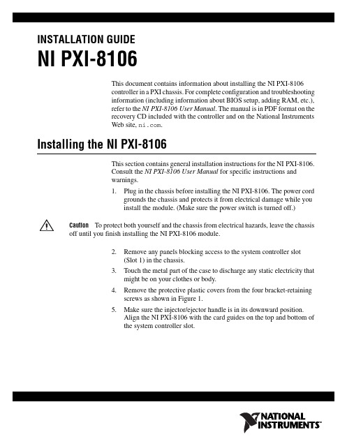
INSTALLATION GUIDENI PXI-8106This document contains information about installing the NI PXI-8106controller in a PXI chassis. For complete configuration and troubleshootinginformation (including information about BIOS setup, adding RAM, etc.),refer to the NI PXI-8106User Manual. The manual is in PDF format on therecovery CD included with the controller and on the National InstrumentsWeb site, .Installing the NI PXI-8106This section contains general installation instructions for the NI PXI-8106.Consult the NI PXI-8106User Manual for specific instructions andwarnings.1.Plug in the chassis before installing the NI PXI-8106. The power cordgrounds the chassis and protects it from electrical damage while youinstall the module. (Make sure the power switch is turned off.)Caution To protect both yourself and the chassis from electrical hazards, leave the chassisoff until you finish installing the NI PXI-8106 module.2.Remove any panels blocking access to the system controller slot(Slot1) in the chassis.3.Touch the metal part of the case to discharge any static electricity thatmight be on your clothes or body.4.Remove the protective plastic covers from the four bracket-retainingscrews as shown in Figure1.5.Make sure the injector/ejector handle is in its downward position.Align the NI PXI-8106 with the card guides on the top and bottom ofthe system controller slot.NI PXI-8106 Installation Guide Figure 1. Removing Protective Screw CapsCautionDo not raise the injector/ejector handle as you insert the NI PXI-8106. Themodule will not insert properly unless the handle is in its downward position so that it does not interfere with the injector rail on the chassis.6.Hold the handle as you slowly slide the module into the chassis until the handle catches on the injector/ejector rail.7.Raise the injector/ejector handle until the module firmly seats into thebackplane receptacle connectors. The front panel of the NI PXI-8106should be even with the front of the chassis.8.Tighten the four bracket-retaining screws on the top and bottom of thefront panel to secure the NI PXI-8106 to the chassis.9.Check the installation.10.Connect the keyboard and mouse to the USB connectors. If you areusing a PS/2 keyboard and a PS/2 mouse, use USB-to-PS/2 adapters toconnect both to the USB connectors on the front panel. You may use aY-splitter adapter to connect both keyboard and mouse to one USBport, leaving the other USB ports free for other peripherals, such as aCD-ROM drive, or secondary hard drive. National Instruments offersa Y-splitter adapter cable, part number 778713-02, available throughthe online catalog at /products .11.Connect the DVI monitor video cable to the DVI connector. If you areusing a VGA monitor, use the DVI-to-VGA adapter included withyour kit.12.Connect peripherals to ports as required by your system configuration.13.Power on the display. Refer to the NI PXI-8106 User Manual fordetails.14.Power on the chassis.15.Verify that the controller boots. If it does not boot, refer to the What Ifthe NI PXI-8106 Does Not Boot? section later in this guide.Figure2 shows an NI PXI-8106 controller installed in the system controllerslot of a National Instruments PXI-1042 chassis. You can place PXI devicesin any other slot.1PXI-1042 Chassis2NI PXI-8106 Controller3Injector/Ejector RailFigure 2. NI PXI-8106 Installed in a PXI ChassisHow to Remove the Controller from the PXI ChassisThe NI PXI-8106 controllers are designed for easy handling. To removethe unit from the PXI chassis:1.Turn off power.2.Remove the cables from the controller front panel.3.Remove the bracket-retaining screws in the front panel.4.Press the injector/ejector handle down.5.Slide the unit out of the chassis.What If the NI PXI-8106 Does Not Boot?Several problems can cause a controller not to boot. Here are some thingsto look for and possible solutions.Things to Notice•Which LEDs come on? The Power OK LED should stay lit. TheDrive LED should blink during boot as the disk is accessed.•What appears on the display? Does it hang at some particular point(BIOS, Operating System, etc.)? If nothing appears on the screen, trya different monitor. Does your monitor work with a different PC? If it © National Instruments Corporation3NI PXI-8106 Installation Guidehangs, note the last screen output that you saw for reference whenconsulting National Instruments technical support.•What has changed about the system? Did you recently move thesystem? Was there electrical storm activity? Did you recently add anew module, memory chip, or piece of software?Things to Try•Make sure the chassis is plugged into a working power source.•Check any fuses or circuit breakers in the chassis or other powersupply (possibly an uninterruptible power supply).•Make sure the controller module is firmly seated in the chassis.•Remove all other modules from the chassis.•Remove any nonessential cables or devices.•Try the controller in a different chassis or a similar controller in thissame chassis.•Clear the CMOS. (Refer to the System CMOS section of theNI PXI-8106 User Manual.)•Recover the hard drive on the controller. (Refer to the Hard DriveRecovery section of the NI PXI-8106 User Manual.)For more troubleshooting information, refer to the NI PXI-8106 UserManual. The manual is in PDF format on the recovery CD included withyour controller and on the National Instruments Web site, . What If I Cannot See the Video?This problem usually results from having the video card output set past thelimits of the monitor. You will need to boot Windows in Safe Mode. To dothis, reboot the controller. As Windows begins to boot, hold down <F8>.You should now be able to reset the video driver to lower settings. Trysetting the resolution to 640 × 480 and the refresh rate to 60 Hz. Once youreboot, you can raise these values again, using the test option in Windows.These settings are accessible through the Advanced tab of the Display itemin the Control Panel. Alternately, you can try a different monitor,preferably a newer and larger one.If the system has been booted to Windows without a monitor attached, thedriver may have defaulted to the video output connector being disabled.Press <Ctrl-Alt-F1> to re-enable the video display in Windows. Press<Ctrl-Alt-F4> to re-enable a DVI display. For more information, refer toKnowledgeBase 3OHCFRD8 at /support.National Instruments, NI, , and LabVIEW are trademarks of National Instruments Corporation.Refer to the Terms of Use section on /legal for more information about NationalInstruments trademarks. Other product and company names mentioned herein are trademarks or tradenames of their respective companies. For patents covering National Instruments products, refer to theappropriate location: Help»Patents in your software, the patents.txt file on your CD, or/patents.© 2006 National Instruments Corporation. All rights reserved.372093A-01Dec06。
国家信息科技USB-634x 635x 636x OEM X Series USB-6341 634
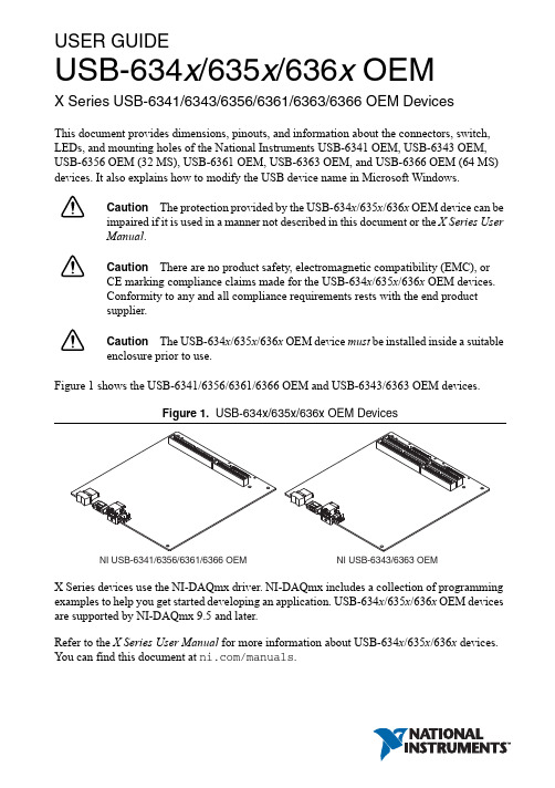
USER GUIDEUSB-634x /635x /636x OEMX Series USB-6341/6343/6356/6361/6363/6366 OEM DevicesThis document provides dimensions, pinouts, and information about the connectors, switch, LEDs, and mounting holes of the National Instruments USB-6341 OEM, USB-6343 OEM, USB-6356 OEM (32MS), USB-6361 OEM, USB-6363 OEM, and USB-6366 OEM (64MS) devices. It also explains how to modify the USB device name in Microsoft Windows.Caution The protection provided by the USB-634x /635x /636x OEM device can beimpaired if it is used in a manner not described in this document or the X Series User Manual .CautionThere are no product safety, electromagnetic compatibility (EMC), orCE marking compliance claims made for the USB-634x /635x /636x OEM devices. Conformity to any and all compliance requirements rests with the end product supplier.CautionThe USB-634x /635x /636x OEM device must be installed inside a suitableenclosure prior to use.Figure 1 shows the USB-6341/6356/6361/6366 OEM and USB-6343/6363 OEM devices.Figure 1. USB-634x/635x/636x OEM DevicesX Series devices use the NI-DAQmx driver. NI-DAQmx includes a collection of programming examples to help you get started developing an application. USB-634x /635x /636x OEM devices are supported by NI-DAQmx 9.5 and later.Refer to the X Series User Manual for more information about USB-634x /635x /636x devices. You can find this document at /manuals.USB-634x/635x/636x OEM Device Specifications AddendumThe Weight and Dimensions (PCB) sections contain specification exceptions for the USB-634x/635x/636x OEM devices to the main specification documents. You can find the appropriate NI 634x/635x/636x specification document for your OEM device at / manuals.WeightUSB-6341/6361 OEM......................................156 g (5.4 oz)USB-6343/6363 OEM......................................167 g (5.8 oz)USB-6356/6366 OEM......................................172 g (6.0 oz)Dimensions (PCB)USB-6341 OEM...............................................175.3 × 162.6 mm (6.9 × 6.4 in.),Refer to Figure2USB-6343 OEM...............................................175.3 × 162.6 mm (6.9 × 6.4 in.),Refer to Figure3USB-6356/6361/6366 OEM.............................175.3 × 162.6 mm (6.9 × 6.4 in.),Refer to Figure4USB-6363 OEM...............................................175.3 × 162.6 mm (6.9 × 6.4 in.),Refer to Figure52||USB-634x/635x/636x OEM User GuideUSB-634x/635x/636x OEM User Guide|© National Instruments|34||USB-634x/635x/636x OEM User GuideFigure 4. USB-6356/6361/6366 OEM DimensionsUSB-634x/635x/636x OEM User Guide|© National Instruments|5Figure 5. USB-6363 OEM Dimensions6||USB-634x/635x/636x OEM User GuideI/O Connector PinoutsFigures6 through10 show the connector pinouts for the USB-6341OEM, USB-6343 OEM, USB-6356/6366 OEM, USB-6361 OEM, and USB-6363 OEM devices.Refer to the X Series User Manual at /manuals for more information aboutUSB-634x/635x/636x OEM device signals and how to connect them.USB-634x/635x/636x OEM User Guide|© National Instruments|78||USB-634x/635x/636x OEM User GuideUSB-634x/635x/636x OEM User Guide|© National Instruments|9Figure 8. USB-6356/6366 OEM Connector Pinout10||USB-634x/635x/636x OEM User GuideUSB-634x/635x/636x OEM User Guide|© National Instruments|11Default NI-DAQmx Counter/Timer PinsBy default, NI-DAQmx routes the counter/timer inputs and outputs to the PFI pins, shown in thefollowing table.12||USB-634x/635x/636x OEM User GuideCounter/Timer Signal Default Terminal Name CTR 0 SRC PFI 8CTR 0 GATE PFI 9CTR 0 AUX PFI 10CTR 0 OUT PFI 12CTR 0 A PFI 8CTR 0 Z PFI 9CTR 0 B PFI 10CTR 1 SRC PFI 3CTR 1 GATE PFI 4CTR 1 AUX PFI 11CTR 1 OUT PFI 13CTR 1 A PFI 3CTR 1 Z PFI 4CTR 1 B PFI 11CTR 2 SRC PFI 0CTR 2 GATE PFI 1CTR 2 AUX PFI 2CTR 2 OUT PFI 14CTR 2 A PFI 0CTR 2 Z PFI 1CTR 2 B PFI 2CTR 3 SRC PFI 5CTR 3 GATE PFI 6CTR 3 AUX PFI 7CTR 3 OUT PFI 15CTR 3 A PFI 5CTR 3 Z PFI 6CTR 3 B PFI 7FREQ OUT PFI 14USB-634x/635x/636x OEM User Guide|© National Instruments|13LEDsUSB-634x/635x/636x OEM devices have two LEDs that reflect the device state. The ACTIVE LED (at reference designator DS4) indicates activity over the bus. The READY LED (at reference designator DS3) indicates whether or not the device is configured. Refer to theX Series User Manual for more information about LED behavior on the USB-634x/635x/636x OEM devices.If you are putting the USB-634x/635x/636x OEM device in an enclosure, you can either seat the supplied lightpipe in the holes (at reference designators DS3 and DS4) on the device, as shown in Figure11, or attach external LEDs, as described in the Attaching External LEDs section. When the lightpipe is attached, the top LED is the ACTIVE LED, and the bottom LED is the READY LED.Attaching External LEDsThree connectors on the device—E1, E2, and E3—allow you to connect an external LED circuit to the device, as shown in Figure11.To connect an external READY LED, use E1 as the positive connection (+5V) and E2 as the negative connection.To connect an external ACTIVE LED, use E1 as the positive connection and E3 as the negative connection.NI recommends that you limit the current to 10mA per LED. You can limit this current by using external resistors, as shown in Figure11.Figure 11. Schematic for External LED Circuits14||USB-634x/635x/636x OEM User GuidePower SwitchThe power switch on the USB-634x/635x/636x OEM device powers the device on and off. Figure12 shows the pins on the power switch and power circuitry.Figure 12. Schematic for the Power Switch (Switch Shown in ON Position) ArrayPin1, VDC In, is connected to VDC through a non-user-replaceable fuse (reference designator F1). The VDC is the voltage provided by the power supply through pin 2 of the power connector (reference designator J10) and must be 11V DC to 30V DC, 30W.Pin2, VDC Out, provides power to the circuitry on the device. When the switch is in the ON position, the VDC power supply from pin1 is routed to pin2.Pin3, 100 kΩ to Ground, connects pin2 to ground through a 100kΩ resistor when the switch is in the OFF position.Connecting the USB-634x/635x/636x OEM Device to Y our ChassisThe USB-634x/635x/636x OEM device features five mounting holes, shown in Figure13. Threeof the mounting holes are plated for customer grounded connections.USB-634x/635x/636x OEM User Guide|© National Instruments|1516| |USB-634x/635x/636x OEM User GuideFigure 13. Customer Mounting Holes (USB-6343/6361/6366OEM Shown)Device ComponentsTable 1 contains information about the components used for interfacing and interacting with the USB-634x /635x /636x OEM devices.Table 1. USB-634x /635x /636x OEM ComponentsComponent(s)Reference Designator(s) on PCBManufacturerManufacturer Part NumberLEDs DS3, DS4, DS1*,DS2*SunLED XZBB54W-1TN Lightpipe —Dialight 515-1061F 34-pinconnector(s)(USB-6341/6356/6361/6366) J33MN2534-6002RB(USB-6343/6363) J3, J450-pinconnector(s)(USB-6341/6356/6361/6366) P13M N2550-6002UB(USB-6343/6363) P1, P2USB connector J9AMP 292304-1Power connectorJ10Phoenix Contact1727566USB-634x/635x/636x OEM User Guide|© National Instruments|17Modifying the OEM Device Name in Microsoft WindowsYou can change how the USB-634x /635x /636x OEM device name appears in the Windows Device Manager 1 in Microsoft Windows when users install the device, as shown in Figure 14. Complete the following steps.NoteYou must have NI-DAQmx 9.5 or later installed on your PC.Figure 14. USB-6363 OEM Device “USB DAQ” in the Windows Device Manager(Windows 7Shown)Power switch SW2C&K E101J1AQE268-pinconnector(s)†(USB-6341/6356/6361/6366) J12Molex71430-0013(USB-6343/6363) J11, J12* Optional LED locations near the mass termination connectors. These are not populated by default.† Optional mass termination connectors. These are not populated by default.1 (Windows XP) You can change how the USB-634x /635x /636x OEM device name appears when usersinstall the device in both the Found New Hardware Wizard that appears when the device is initially installed and in the Windows Device Manager.Table 1. USB-634x /635x /636x OEM Components (Continued)Component(s)Reference Designator(s) on PCBManufacturerManufacturer Part Number18||USB-634x/635x/636x OEM User Guide1.Locate the OEM x .inf file in the y :\WINDOWS\inf\ directory, where x is the random number assigned to the INF file by Windows, and y :\is the root directory where Windows is installed.Security updates to Microsoft Windows and NI-DAQmx create random INF files for NI hardware. Windows assigns random file numbers to all INF files, which causes the user to search through several INF files until the correct file is located.If you want to revert back, save a copy of this file as OEM x _original.inf in a different location.2.Edit the device INF file by opening OEM x .inf with a text editor.At the bottom of this file, in the [Strings] section, are the descriptors where Windows looks to identify the device. Locate the four lines of text that contain in quotes the descriptors for the device name you are modifying. Change the descriptor on all four lines to the new device name, as shown in Figure 15.Figure 15. INF File Descriptors Changed to “My Device” (Windows 7 Shown)3.Save and close the INF file.4.Open the Windows Device Manager. In the Device Manager, notice that the OEM device now appears as My Device , as shown in Figure 16.11 (Windows XP) In the Device Manager, right-click the OEM device under Data Acquisition Devices,and select Uninstall . Power down the OEM device and disconnect the USB cable from your PC. When you reconnect and power on the device, it appears as My Device in Windows Device ManagerOrigin a l FileModified File© 2012–2017 National Instruments. All rights reserved. 371041C-01Feb17Refer to the NI Trademarks and Logo Guidelines at /trademarks for more information on NI trademarks. Other product and company names mentioned herein are trademarks or trade names of their respective companies. For patents covering NI products/technology, refer to the appropriate location: Help»Patents in your software, the patents.txt file on your media, or the National Instruments Patents Notice at/patents . You can find information about end-user license agreements (EULAs) and third-party legal notices in the readme file for your NI product. Refer to the Export Compliance Information at /legal/export-compliance for the NI global trade compliance policy and how to obtain relevant HTS codes, ECCNs, and other import/export data. NI MAKES NO EXPRESS OR IMPLIED WARRANTIES AS TO THE ACCURACY OF THE INFORMATION CONTAINED HEREIN AND SHALL NOT BE LIABLE FOR ANY ERRORS. U.S. Government Customers: The data contained in this manual was developed at private expense and is subject to the applicable limited rights and restricted data rights as set forth in FAR 52.227-14, DFAR 252.227-7014, and DFAR 252.227-7015.Figure 16. “My Device” in the Windows Device Manager (Windows 7Shown)NoteWhen the device is initially installed, Windows may display the followingmessages: USB DAQ detected!, and then USB DAQ: Device driver software installed successfully . These alert messages cannot be changed.NoteModifying the INF file will not change the USB-634x /635x /636x OEMdevice name in Measurement & Automation Explorer (MAX).。
NI Windows 10支持和PCIe系列产品概述说明书

Supercharging T est and Measurement SystemsWith Windows 10, an Intel Xeon CPU, and PCI Express Gen 3 TechnologyC O N T E N T SWindows 10 SupportPXIe-8880 Intel Xeon-Based Embedded ControllerPXIe-1085 24 GB/s ChassisPXIe-8830mc Coprocessing ModuleKey Application AreasAdditional ResourcesWindows 10 SupportAs the test and measurement industry continues to evolve, the reliance on software to perform the majority of instrumentation continues to increase. Virtual instrumentation, which was a term coined in the late 1980s torepresent the importance of software, is now common terminology in the industry. A synergistic combination of the OS and application development environment is crucial to the success of virtual instrumentation. NI worked with Microsoft to ensure that all the application development environments and hardware device drivers work seamlessly and harvest the extensive capabilities of the OS.Starting from Microsoft DOS and Windows 3.1 to the latest and greatest Windows 10 OS, NI’s hardware and software tools have been tested and optimized to perform at their best with the operating system. With renewed focus on system security and application optimization and best-in-class driver support, NI recommends Windows10 for most test and measurement applications. National Instruments is proud to be the first test andmeasurement vendor to provide PXI Embedded controllers with Windows 10NI recommends Windows.For more information, visit /windows10.Figure 1. The PXIe-1085 24 GB/s Chassis, PXIe-8880 Intel Xeon-Based Embedded ControllerWith Windows 10 Support, and Various Modular InstrumentsPXIe-8880 Intel Xeon-based Embedded ControllerNI collaborated with Intel to deliver the server-class power of Intel Xeon processors to the test and measurement market. The PXIe-8880 embedded controller features eight cores, up to 24 GB of DDR4 memory, and 24 lanes of PCI Express Gen 3 connectivity to the backplane. This gives engineers and scientists up to twice the processing power and bandwidth compared with previous-generation controllers.Controller Technology at a Glance∙Intel Xeon E5-2618L v3 processor With 2.3 GHz (base) and 3.4 GHz (Turbo Boost)∙8 physical and 16 logical CPU Cores∙8 GB DDR4 1866 MHz RAM (standard); 24 GB maximum∙Up to 24 GB/s system bandwidth (each direction)∙240 GB, 1.8 in. SSD hard drive∙ 2 USB 3.0, 4 USB 2.0, 1 DisplayPort v1.2, 2 Gigabit Ethernet, GPIB, SMB trigger∙Windows 10 64-bit or LabVIEW Real-Time OSSee the Resources section of the PXIe-8880 model page for the full user manual and specifications.Figure 2. (Left) Teardown View of PXIe-8880 Embedded Controller With Intel Xeon Processor Exposed and two 8 GB RAM Upgrades; (Right) Front View of the PXIe-8880 Embedded Controller With Peripherals Performance BenchmarksTo understand the value of the new PXIe-8880 controller, consider the raw performance power of the CPU. Because most test and measurement systems are more computationally intensive than graphically intensive, we used more processor-centric CPU benchmarks. Figure 3 shows that the new PXIe-8880 with an eight-core Intel Xeon E5-2618L v3 processor performs 76 percent better than the previous-generation PXIe-8135 quad-core Intel Core i7-3610QE processor in the CPU Mark benchmark.Figure 3. The PXIe-8880 has a 76 percent CPU Mark performance improvementcompared to the previous-generation PXIe-8135 embedded controller.You also need to look at how the PXIe-8880 performs when used with test and measurement software, such as LabVIEW graphical system design software. A processor-intensive measurement that is commonly used in test and measurement is the fast Fourier transform (FFT). In Figure 4 below, you can see that the PXIe-8880 can compute 91 percent more FFTs than the previous-generation PXIe-8135 quad-core Intel Core i7-3610QE processor in the benchmarked time window. LabVIEW is a natively multithreading application software, so it highly leverages the eight cores of the Intel Xeon processor of the PXIe-8880 embedded controller.Figure 4. The PXIe-8880 computes 91 percent more LabVIEW FFTs comparedto the previous-generation PXIe-8135 embedded controller.“The use of the latest Intel Xeon processors is a new milestone for our collaboration with NI. The Internet of Things requires the highest possible processing power to reduce time to market and lower the cost of test, and NI’s approach with PXI is critical toward that goal.”—Shahram Mehraban Director, Market Development for Industrial IoT, IntelPXIe-1085 24 GB/s ChassisSince the inception of the PXI standard in 1997, NI has played a key role in building a foundation for innovation by continually delivering a broad and high-performance chassis portfolio to meet the I/O point and performanceneeds of customer applications. With the latest chassis release, NI has delivered the first PXI chassis based on PCI Express Gen 3 technology to offer engineers twice the slot and system bandwidth of previous-generation chassis.Chassis Technology at a Glance∙PXI Express with PCI Express Gen 3 technology∙16 hybrid slots; 1 PXI Express system timing slot; 1 system slot∙Up to 24 GB/s system bandwidth (each direction)∙Up to 8 GB/s slot bandwidth (each direction)∙Removable power shuttle; 925 W total system power∙38.25 W power and cooling capability per slot∙Optional rack-mount kitSee the Resources section of the PXIe-1085 24 GB/s model page for the full user manual and specifications.Figure 5. Front View of a Vacant PXIe-1085 24 GB/s ChassisPXI Express SpecificationAs the complexity of customer applications and demand for processing power and bandwidth have grown over the past decades, the PXI specification has evolved to meet these needs. Initially PXI was based on PCI technology and provided 132 MB/s of data bandwidth. This specification then evolved into PXI Express by using PCI Express technology, which sends data serially through pairs of transmit and receive connections called lanes, providing the ability to transfer data at 250 MB/s per direction with PCI Express Gen 1 technology. Multiple lanes are grouped together to form x4, x8, and x16 links to increase bandwidth.This then grew to 500 MB/s per lane with PCI Express Gen 2 technology. With the release of the PXIe-1085 24 GB/s chassis, the industry’s first chassis that is based on PCI Express Gen 3 technology, the lane bandwidth has been doubled to 1 GB/s per lane, and with 24 data lanes (x24), a total of 24 GB/s of data per direction can be sent from the controller to the PXI Express backplane as seen in Figure 6 below.The system bandwidth outlined in the previous paragraph addresses only the amount of data that can be transferred between the system controller and the chassis. When using peer-to-peer (P2P) communication between peripheral modules, the total amount of data that can be transferred in the chassis increases dramatically. As an example, with three peripheral modules streaming to the system controller at 8 GB/s and seven pairs of modules using P2P at 8GB/s, in theory, total system bandwidth becomes 80 GB/s in single direction and 160 GB/s bidirectionally. Actual system bandwidth will vary based on many factors such as memory bandwidth, PCI Express packet sizes and overhead, single versus bidirectional traffic, and so on.Figure 6. System Bandwidth for Each Generation of PXI and PXI ExpressBased on the 24 Available Data Lanes (x24)All Hybrid SlotsAlong with advancements in chassis communication buses to incorporate the latest PC technology, PXI peripheral modules have evolved from PXI to PXI Express to take advantage of PCI Express communication bus capabilities. To ensure module compatibility between PXI and PXI Express modules, the PXI specification added the hybrid slot. With this slot, you can insert hybrid-compatible PXI or PXI Express peripheral modules in PXI chassis and use any previous investments in hybrid-compatible PXI modules. As with the previous 12 GB/s PXIe-1085 chassis, the 24 GB/s variant is an 18-slot chassis (1 system controller + 17 peripheral slots) with 16 hybrid slots.PXI Backplane TechnologyA key benefit of the PXI platform over traditional instrumentation is the integration of triggering, power, reference clocks, and data buses, which are normally external cables, into the PXI chassis backplane. For the PXIe-1085 24 GB/s chassis based on PCI Express Gen 3 technology, the key innovation is implementation of two Gen 3 switches as seen in Figure 7. These switches handle the routing of information from module to module and between the modules and controllers.Figure 7. Rear View of the PXIe-1085 24 GB/s Chassis With the Power Shuttle Removedto View the PCI Express Gen 3 Switching TechnologyPXIe-8830mc Coprocessing ModuleA recent development in the PXI platform is the PXI MultiComputing (PXImc) specification, which allows two ormore intelligent systems to exchange data through PCI Express. Previously, you could use the PXIe-8383peripheral slot to physically connect to a remote processor such as a workstation computer. The new PXIe-8830mc is an embedded coprocessing module that you can install directly into any PXI Express peripheral slot to quickly add processing power to your system. For example, in an 18-slot chassis, you can combine the PXIe-8880 with eight NI PXIe-8830mc co-processing modules for a total of 40 physical cores.Coprocessing Module at a Glance∙Intel Core i7-4700EQ processor∙ 4 Physical and 8 logical cores∙ 2 USB 2.0, 1 Gigabit Ethernet LAN ports∙ 4 GB (1 x 4 GB DIMM) single-channel 1600 MHz DDR3 RAM∙Up to 4GB/s theoretical (2.7 GB/s actual) bandwidth for data transfer (single direction)∙ 5 μs t otal (software plus hardware) latency between coprocessing module and main CPU See resources section of PXIe-8830mc model page for full user manual and specifications.Figure 8. A PXI System Full of High-Bandwidth, Signal-Processing Intensive RF Instrumentation and a PXIe-8830mc Coprocessing Module in Slots 6 and 7 to Add Four Processing Cores“Over the past two decades, we have witnessed a gradual shift from traditional instru mentation in favor of the PXI platform for automated test. With the addition of Intel Xeon processor technology, we expect the adoption of PXI to only increase for high-performance applications.”—Jessy Cavazos Industry Manager, Measurement and Instrumentation Frost & SullivanKey Application AreasIn addition to the key application areas below, the new chassis and controller are ideal for any computationally intensive or high-bandwidth test and measurement application, as well as any application that must scale into the future without sacrificing performance.Wireless TestSince the implementation of the AMPS protocol in 1978, wireless communication protocols have continuallydemanded more bandwidth to transmit data. This means that the test systems built to validate theimplementation of these protocols in devices must be able to acquire, analyze, and present large sets of datafrom instrumentation. With the average life span of five to seven years for a test system, wireless test engineers are adopting a modular approach to mitigate retooling costs to update software and hardware as each newprotocol becomes implemented.Semiconductor TestThough test systems for semiconductor, such as the Semiconductor Test System (STS), do not consume large sets of data, they do need to consume many sets of data in parallel to increase their test throughput or part per hour. A big contributor for multisite test throughput is the parallel test efficiency (PTE) of a test system, which is typically fixed for a system. But for a modular approach such as the STS, the ability to add an eight-core IntelXeon processor and powerful multicore test executive software like TestStand provides an economical approach for increasing PTE, and therefore production throughput for semiconductor test engineers.5G PrototypingPrototyping fifth-generation (5G) cellular systems requires intense signal processing, tight synchronization,control functionality, and the I/O points that can achieve multigigabit per second data rates. Along with powerful software such as the LabVIEW Communications System Design Suite, the multicore processing and high-bandwidth of the PXIe-8880 controller and PXIe-1085 24 GB/s chassis provide an ideal starting point for anyprototyping platform.Building a Future-Proofed Test and Measurement System on the Bedrock of NI PXIThe past two decades have seen more technological innovation than we could have ever predicted. It tookroughly 18 years to go from 1G to 2G cellular communication but LTE replaced 3G in just under 6 years. We have seen analog-to-digital converters go from hundreds of MS/s to tens of GS/s. And the predictions around theimpact of the Internet of Things, which encourage us to enable every “thing” to sense, compute andcommunicate, will all be exceeded if the adoption rates continue at their current trajectory.But innovation has implications. Going from “it works” in a design environment to “it works” when the useropens the box requires multiple test and measurement steps, and the need for increased bandwidth andprocessing power is increasing each year. Though sacrificing product quality is not a preferable option, neither is spending valuable time and money to bolt on additional hardware and software each time a new productreleases. Predicting the future of product innovation is not possible, but choosing an architecture that accounts for flexibility and scalability is. With the modularity to meet evolving requirements, the combination of the PXIe-8880 embedded controller, the PXIe-1085 24 GB/s chassis, Windows 10 support, and the largest portfolio ofmodular instrumentation makes PXI a zero-compromise solution for any test and measurement application. Additional ResourcesPXIe-8880 Embedded ControllerPXIe-1085 24 GB/s ChassisPXIe-8830mc Co-Processing ModuleLearn about the NI PXI PlatformStreaming Architecture of the Industry’s Highest Performance PXI Express Platform©2016 National Instruments. All rights reserved. LabVIEW, National Instruments, NI, NI TestStand, and are trademarks of National Instruments. Other product and company names listed are trademarks or trade names of their respective companies.。
NI6251
The following sections contain information about the NI PCI/PCIe/PXI/PXIe-6251, USB-6251 Screw Terminal, USB-6251 BNC, and USB-6251 Mass Termination devices. NI PCI/PCIe/PXI/PXIe-6251 NI PCI/PCIe/PXI/PXIe-6251 Pinout Figure A-28 shows the pinout of the NI PCI/PCIe/PXI/PXIe-6251. For a detailed description of each signal, refer to the I/O Connector Signal Descriptions section of Chapter 3, Connector and LED Information. Note M Series devices may be used with most E Series accessories. However, some E Series accessories use different terminal names. Refer to the M Series and E SeriesPinout Comparison section of Chapter 3, Connector and LED Information, for more information.Counter/Timer Signal 计数器/定时器信号Default Pin Number (Name)默认的PIN 号码(名字) *:Note For more information about default NI-DAQmx counter inputs, refer to Connecting Counter Signals in the NI-DAQmx Help or the LabVIEW Help in version 8.0 or later.有关默认NI-DAQmx 计数器输入更多的信息,请注意,是指连接在NI-DAQmx 帮助或在8或更高版本的LabVIEW 帮助计数器信号。
NI最新推出一系列USB数据采集卡
NI最新推出一系列USB数据采集卡
无
【期刊名称】《自动化信息》
【年(卷),期】2004(000)006
【总页数】1页(P8)
【作者】无
【作者单位】无
【正文语种】中文
【中图分类】TN492
【相关文献】
1.NI最新推出一系列USB数据采集卡 [J],
2.NI推出高精度多功能USB接口数据采集设备——NIUSB-6281及USB-6289功能增强型18位分辨率设备 [J], 无
3.NI为数据采集设定新标准 USB采集卡即插即用 [J],
4.NI最新推出一系列USB数据采集卡最先推出的5款全新USBDAQ卡,为您提供即插即用的便携式数据采集方案 [J],
5.NI推出高精度多功能USB接口数据采集设备NIUSB-6281及USB-6289功能增强型18位分辨率设备 [J],
因版权原因,仅展示原文概要,查看原文内容请购买。
- 1、下载文档前请自行甄别文档内容的完整性,平台不提供额外的编辑、内容补充、找答案等附加服务。
- 2、"仅部分预览"的文档,不可在线预览部分如存在完整性等问题,可反馈申请退款(可完整预览的文档不适用该条件!)。
- 3、如文档侵犯您的权益,请联系客服反馈,我们会尽快为您处理(人工客服工作时间:9:00-18:30)。
USER GUIDENI USB-622x /625x /628x OEMM Series USB-6221/6225/6229/6251/6255/6259/6281/6289 OEM DevicesThis document provides dimensions, pinouts, and informationabout the connectors, switch, LEDs, and chassis ground of the National Instruments USB-6221 OEM, USB-6225 OEM, USB-6229 OEM,USB-6251 OEM, USB-6255 OEM, USB-6259 OEM, USB-6281 OEM, and USB-6289 OEM devices. It also explains how to modify the USB device name in Microsoft Windows.CautionThere are no product safety, electromagnetic compatibility (EMC), orCE marking compliance claims made for the USB-622x /625x /628x OEM devices. Conformity to any and all compliance requirements rests with the end product supplier.Caution(USB-628x Devices) Exercise caution when placing USB-628x OEM devices insidean enclosure. Auxiliary cooling may be necessary to keep the device under the maximum ambient temperature rating of 45 °C, as specified in the NI 628x Specifications .Figure 1 shows the USB-6221/6251/6281 OEM and USB-6225/6229/6255/6259/6289 OEM devices.Figure 1. USB-622x /625x /628xOEM DevicesRefer to the NI 622x Specifications document for USB-6221/6225/6229specifications, the NI 625x Specifications document forUSB-6251/6255/6259 specifications, and the NI 628x Specificationsdocument for USB-6281/6289 specifications. Refer to the M Series UserManual for more information about USB-622x/625x/628x devices.You can find all documentation at /manuals. DimensionsFigure2 shows the dimensions of the USB-6221/6251/6281 OEM device. NI USB-622x/625x/628x OEM User Figure 2. USB-6221/6251/6281 OEM Dimensions in Inches (Millimeters)© National Instruments Corporation3NI USB-622x/625x/628x OEM User GuideFigure3 shows the dimensions of the USB-6225/6229/6255/6259/6289OEM device.Figure 3. USB-6225/6229/6255/6259/6289 OEM Dimensions in Inches (Millimeters) NI USB-622x/625x/628x OEM User I/O Connector PinoutsFigures4 through9 show the connector pinouts for the USB-6221 OEM,USB-6225 OEM, USB-6229 OEM, USB-6251 OEM, USB-6255 OEM,USB-6259 OEM, USB-6281 OEM, and USB-6289 OEM devices.Refer to the M Series User Manual at /manuals for moreinformation about USB-622x/625x/628x signals and how to connect them.© National Instruments Corporation5NI USB-622x/625x/628x OEM User GuideFigure 4. USB-6221 OEM Connector PinoutNI USB-622x/625x/628x OEM User Figure 5. USB-6225 OEM Connector Pinout© National Instruments Corporation7NI USB-622x/625x/628x OEM User GuideFigure 6. USB-6229 OEM Connector PinoutNI USB-622x/625x/628x OEM User Figure 7. USB-6251/6281 OEM Connector Pinout© National Instruments Corporation9NI USB-622x/625x/628x OEM User GuideFigure 8. USB-6255 OEM Connector PinoutNI USB-622x/625x/628x OEM User Figure 9. USB-6259/6289 OEM Connector PinoutDefault Counter/Timer PinoutsBy default, NI-DAQmx routes the counter/timer inputs and outputs to thePFI pins, shown in Table1.Table 1. NI-DAQmx Default Counter/Timer PinsCounter/Timer Signal Default Terminal NameCTR 0 SRC PFI 8CTR 0 GATE PFI 9CTR 0 AUX PFI 10CTR 0 OUT PFI 12CTR 0 A PFI 8CTR 0 Z PFI 9CTR 0 B PFI 10CTR 1 SRC PFI 3CTR 1 GATE PFI 4CTR 1 AUX PFI 11CTR 1 OUT PFI 13CTR 1 A PFI 3CTR 1 Z PFI 4CTR 1 B PFI 11FREQ OUT PFI 14Attaching External LEDsUSB-622x/625x/628x OEM devices have two LEDs that reflect the devicestate. The green READY LED indicates when the device is powered on andconfigured as a USB device. The yellow ACTIVE LED indicates USB busactivity.Three connectors on the device allow you to connect an external LEDcircuit to the device, as shown in Figure10. To connect an external READYLED, use E1 as the positive connection (+3.3 V) and E2 as the negativeconnection. To connect an external ACTIVE LED, use E1 as the positiveconnection and E3 as the negative connection. E1 is current limited witha100 Ω resistor to the 3.3V internal supply. This configuration limitsthe current to approximately 16mA into a single external LED orapproximately 8 mA each when both LEDs are lit. You also can limit thiscurrent further by using external resistors, also shown in Figure10.Figure 10. Schematic for External LED CircuitsPower SwitchThe power switch on the USB-622x/625x/628x OEM device powers thedevice on and off. Figure11 shows the pins on the power switch andcircuitry.Figure 11. Schematic for the Power SwitchPin1, VDC In, is connected to VDC through the fuse (reference designatorXF1). The VDC is the voltage provided by the power supply through thepower connector (reference designator J4/J6/J81) and must be 11–30VDC,20W.Pin2, VDC Out, provides power to the circuitry on the device. When theswitch is in the On position, the VDC power supply from pin1 is routed topin2.Pin3, 100 kΩ to Ground, connects pin2 to ground through a 100kΩresistor when the switch is in the Off position.1 The power connector is designated as J4 on USB-6225/6255 OEM devices, J6 on USB-6221/6229 OEM devices, and J8 on USB-6251/6259/6281/6289 OEM devices.Connecting the USB-622x /625x /628x OEM Device to Your ChassisThe USB-622x /625x /628x OEM device includes several plated mounting holes that are designed for customer grounded connections, as shown in Figure 12.CautionDo not use the holes labeled A in Figure 12 as mounting holes.Figure 12. Customer Mounting Holes (USB-6225/6229/6255/6259/6289OEM Shown)Caution(USB-628x Devices) Exercise caution when placing USB-628x OEM devices insidean enclosure. Auxiliary cooling may be necessary to keep the device under the maximum ambient temperature rating of 45 °C, as specified in the NI 628x Specifications.Replacing FusesUSB-622x /625x /628x OEM devices have a replaceable T 2A 250V (5×20mm) fuse that protects the device from overcurrent through the power connector.(USB-628x Devices Only) USB-628x OEM devices also have a replaceableF 2A 125V fuse that protects the device from overcurrent through the +5 V terminal(s).Replacement fuse information can be found in Table 2. To replace a broken fuse in USB-622x /625x /628x OEM devices, complete the following steps.1.Power down and unplug the device.2.Replace the broken fuse while referring to Figure 13 for the fuse locations.Figure 13. USB-622x /625x /628x OEM Fuse Locations1T 2A 250V (5 x 20 mm) F us e2F 2A 125V F us e on U S B-628x OEM DevicesDevice ComponentsTable2 contains information about the components used for interfacingand interacting with the USB-622x/625x/628x OEM device.Table 2. USB-622x/625x/628x OEM ComponentsComponent Reference Designator(s) on PCB Manufacturer Manufacturer Part NumberLEDs DS1Dialight553-033234-pin connectors(USB-6221/6251/6281 OEM) J13M N2534-6002RB(USB-6225/6229/6255/6259/6289OEM) J1, J250-pin connectors(USB-6221/6251/6281 OEM) P13M N2550-6002UB(USB-6225/6229/6255/6259/6289OEM) P1, P2USB connector J3AMP787780-1 Power connector(USB-6221/6229OEM) J6Switchcraft722RA(USB-6225/6255OEM) J4(USB-6251/6259/6281/6289OEM) J8Power switch SW1ITT Industries,CannonE101J1A3QE2 T 2A 250V fuse XF1Littelfuse218.002XPF 2A 125V fuse(USB-6281/6289OEM) F1Littelfuse045300268-pin connectors*(USB-6221 OEM) J8Honda PCS-E68RLMD1+ (USB-6225/6229/6255 OEM) J7, J8(USB-6251/6281OEM) J7(USB-6259/6289OEM) J6, J7* Optional mass termination connectors. These are not populated by default.Modifying the USB Device Name in Microsoft WindowsYou can change how the USB-622x/625x/628x OEM device name appearswhen users install the device in both the Found New Hardware Wizard thatappears when the device is initially installed and in the Windows DeviceManager.Windows Vista/XP UsersFigure14 depicts how a USB-6251 OEM device name appears in theFound New Hardware Wizard and Windows Device Manager.Figure 14. USB-6251 OEM Device in the Found New Hardware Wizard andDevice Manager (Windows Vista/XP)To modify the device name in the Found New Hardware Wizard andWindows Device Manager in Microsoft Windows Vista/XP, complete thefollowing steps.Note You must have NI-DAQmx 8.7 or later installed on your PC.1.Locate the OEM x.inf file in the y:\WINDOWS\inf\ directory,where x is the random number assigned to the INF file by Windows,and y:\is the root directory where Windows is installed.NoteNew security updates to Microsoft Vista and NI-DAQ 8.6 or later create random INF files for NI hardware. Windows assigns random file numbers to all INF files, which causes the user to search through several INF files until the correct file is located.If you want to revert back, save a copy of this file as OEM x _original.inf in a different location.2.Edit the device INF file by opening OEM x .inf with a text editor. At the bottom of this file are the descriptors where Windows looks to identify the device. Locate the two lines of text that contain in quotes the descriptors for the device name you are modifying. Change the descriptor on both lines to the new device name, as shown in Figure 15.Figure 15. INF File Descriptors Changed to “My Device” (Windows Vista/XP)3.Save and close the INF file.4.Go to the Windows Device Manager.(Windows Vista) In the Device Manager, notice that the OEM device now appears as My Device , as shown in Figure 16.(Windows XP) In the Device Manager, right-click the OEM device underData Acquisition Devices, and select Uninstall . Power down the OEMdevice and disconnect the USB cable from your PC.Original FileModified FileWhen you reconnect and power on the device, it appears as My Device inthe Found New Hardware Wizard and Windows Device Manager, as shownin Figure16.Note When the device is initially installed, the Windows alert message may display the following: Found New Hardware: M Series USB 62xx (OEM). This message appears for a few seconds until the custom name appears and the Found New Hardware Wizard is launched. This alert message device name cannot be changed.Figure 16. “My Device” in the Found New Hardware Wizard andDevice Manager(Windows Vista/XP)Note Modifying the INF file will not change the USB-622x/625x/628x OEM device name in Measurement & Automation Explorer (MAX).© National Instruments Corporation 21NI USB-622x/625x/628x OEM User GuideWindows 2000 UsersFigure 17 depicts how a USB-6251 OEM device name appears in theFound New Hardware Wizard and Windows Device Manager.Figure 17. USB-6251 OEM Device in the Found New Hardware Wizard andDevice Manager (Windows 2000)To modify the device name in the Found New Hardware Wizard andWindows Device Manager in Windows 2000, complete the following steps.Note You must have NI-DAQmx 8.7 or later installed on your PC.1.Locate the nimioxsu.inf file in the x :\WINNT\inf\ directory,where x :\ is the root directory where Windows is installed.If you want to revert back, save a copy of this file asnimioxsu_original.infin a different location.2.Edit the device INF file by opening nimioxsu.inf with a text editor.At the bottom of this file are the descriptors where Windows looks toidentify the device. Locate the two lines of text that contain in quotesthe descriptors for the device name you are modifying. Change thedescriptor on both lines to the new device name, as shown in Figure18.Original FileModified FileFigure 18. INF File Descriptors Changed to “My Device” (Windows 2000)3.Save and close the INF file.4.Go to the Windows Device Manager, right-click the OEM device underData Acquisition Devices, and select Uninstall.5.Power down the OEM device and disconnect the USB cable fromyour PC.NI USB-622x/625x/628x OEM User National Instruments, NI, , and LabVIEW are trademarks of National Instruments Corporation.Refer to the Terms of Use section on /legal for more information about NationalInstruments trademarks. Other product and company names mentioned herein are trademarks or tradenames of their respective companies. For patents covering National Instruments products, refer to theappropriate location: Help»Patents in your software, the patents.txt file on your media, or/patents .© 2006–2008 National Instruments Corporation. All rights reserved.371910E-01Jun08When you reconnect and power on the device, it appears as My Device inthe Found New Hardware Wizard and Windows Device Manager, as shownin Figure 19.Note When the device is initially installed, the Windows alert message may display the following: Found New Hardware: M Series USB 62xx (OEM). This message appears for a few seconds until the custom name appears and the Found New Hardware Wizard is launched. This alert message device name cannot be changed.Figure 19. “My Device” in the Found New Hardware Wizard andDevice Manager (Windows 2000)Note Modifying the INF file will not change the USB-622x /625x /628x OEM device namein Measurement & Automation Explorer (MAX).。
