PLC国产之路,5%的反思——小型PLC,国产PLC发展的困境
PLC5系统应用简介

•4 SLOT •8 SLOT
•12
•16
•1771
•1771
•1S7L7O1 T
•1S7L7O1 T
•I/O柜A架1最B 左槽安装A处2B理器、适配A器3B模块,不占用槽A数4B。
•I/O柜架背板有一开关和一组组态插头;8位组合开关用来确定一些处理 器工作方式:寻址方式;输出最后状态;内存保护。
•组态插头:用来选择外部电源或电源模块(内部电源)
PLC5系统应用简介
•硬件介绍 •编程基础 •指令介绍 •应用举例
•纲要
•PLC概述:
•1、PLC定义:可程序逻辑控制器(PLC,Programmable Logic • Controller),是一种固态电子装置,主要利用输入/输 出装置的回授信号及储存程序,控制机械或程序的操作。在 工厂自动化(FA)系统中,PLC因为具备价格便宜、系统稳 定及环境适应性佳的特点,故一直为自动化业界所采用。
•
PLC5/40L;PLC5/40E;PLC5/40C;PLC5/60;PLC5/60L;
•
PLC5/80;PLC5/80E。
•区别:内存区别;I/O点数区别;通讯端口区别;
•E:ETHERNET通讯口;C:CONTROLLNET通讯口;L:LOCAL I/O通讯 口。
•2、PLC系列处理器间的相同点: ➢相同的物理尺寸,安装在通用1771-I/0柜架最左槽。 ➢可带8点、16点、32点1771通用I/O模块和智能I/O模块。 ➢相同的编程软件和编程终端。 ➢相同的基本指令。 ➢可与AB其它设备进行通迅(网络通讯口:DH+、REM I/O)
•最大电缆长度
•DH+通讯:可接64个终 端
•网络结构:
K5系列PLC使用简要说明(20130624)
3
80 81 22 85 86 87 95 96 97 一般错误 136 137 138 139 300 301 320 321 322 323 324 325 326 327 329 330 331 332 333 334 335 336 341 350 351 360
上电时,第 5 个扩展模块超时没有响应。 上电时,第 5 个模块响应错误。 第 5 个扩展模块与硬件配置中的类型不一致。 上电时,第 6 个扩展模块超时没有响应。 上电时,第 6 个模块响应错误。 第 6 个扩展模块与硬件配置中的类型不一致。 上电时,CPU 模块发送扩展通信报文失败。 上电时,CPU 模块扩展总线进入错误被动状态。 上电时,CPU 模块扩展总线进入总线关闭状态。
内存、指令错误寄存器
SM
SMB0(只读) SM0.2 SMB1(只读)
功能描述 若上电后 PLC 检测到 RAM 中的掉电保持数据丢失,则将该位置 1,否则置 0。
5
SM1.0 SM1.1 SM1.2 SM1.3 SM1.4 SM1.5 SM1.6
当执行 DIV、MOD 指令时,若除数为 0,则该位被置 1。 当执行 LOG、LN、SQRT 指令时,若参数值为 0,则该位被置 1。 当执行类型转换指令时,若结果超过了范围,则该位被置 1。 当执行 I_TO_BCD 指令时,若数值不是有效的 BCD 码,则该位被置 1。 当执行 A_TO_H 指令时,若字符不能被转换为有效的数值,则该位被置 1。 当执行 R_TO_A 指令时,若不能被转换为有效的字符串,则该位被置 1。 当执行 FOR 指令时,若参数错误,则该位被置 1。
一般错误 一般错误是 PLC 执行某项功能时发生错误,但 PLC 能够容忍这种错误,可以继续正确运行用户程序,其结果是可
PLC5产品概述
PLC5产品概述PLC5(Programmable Logic Controller 5)是由罗克韦尔自动化公司(Rockwell Automation)开发的一款工业控制器。
PLC5系列是PLC (可编程逻辑控制器)领域的经典产品,已经在工业控制和自动化领域中广泛应用。
PLC5系列的特点是稳定可靠、功能强大、灵活可扩展。
它是一种基于各种硬件模块相互连接和互联的可编程逻辑控制器,能够集成各种传感器、执行器和外部设备,实现对工业过程的全面控制和监控。
PLC5系列控制器采用Modular架构,不同的模块可以根据系统需求灵活组合,满足不同规模和复杂度的应用。
PLC5系列的主要应用领域包括制造业、能源、水处理、物流等。
在制造业中,PLC5系列广泛应用于生产线控制、机械装置控制、运输设备控制等方面。
在能源行业中,PLC5系列可以用于电力系统控制、石油化工过程控制等。
在水处理领域,PLC5系列可以实现对污水处理设备、供水设备的控制和监控。
在物流领域,PLC5系列可以应用于自动化仓储、分拣设备控制等场景。
PLC5系列有多个型号可供选择,包括PLC-5/10、PLC-5/11、PLC-5/12等。
不同型号具有不同的输入/输出点数、存储容量和运算速度,可以根据实际应用需求选择合适的型号。
PLC5系列支持多种通信接口,包括远程通信接口、以太网接口、以及通用串行接口等,可以方便地与上位机、下位机或其他PLC进行通信和数据交换。
此外,PLC5系列还提供了编程软件RSLogix 500,用户可以使用该软件进行程序的开发和调试。
PLC5系列具备故障检测和自动恢复功能,能够实时监测系统状态,如传感器是否正常工作、执行器是否执行命令等,一旦发现异常情况,PL5系列会立刻生成相应的报警信号并采取相应的措施。
此外,PLC5系列还支持在线升级和调试功能,可以方便地进行系统维护和升级。
总之,PLC5系列是一款功能强大、灵活可靠的工业控制器。
三菱PLC指令传送比较指令及实际应用
X1——启动
Y0——电源
X2——停止
Y1——Y接法
Y2——△接法
X1
X2
X1
Y0
Y1
1s
Y1
5s
T1
Y0
Y2
T2
X2
十六进制 Y3 Y2 Y1 Y0
0
0000
1
0001
2
0010
3
0011
4
0100
5
0101
6
0110
7
0111
8
1000
9
1001
MOV H03
T1 K50
K1Y0
MOV H01
T2 K60
图5-21
四、块传送
1.指令代码:FNC15,助记符:BMOV,BMOV(P) 2.功能:把指定操作数软元件区的内容传送到 目标操作数软 元件区中,连续源单元→连续目标单元。 3.格式
X0
S Dn
BMOV D5 D10 K3
S:KnX,KnY,KnM,KnS,T,C,D——指定源元件的首 地址 D:KnX,KnY,KnM,KnS,T,C,D——指定目标元件的 首地址 n:≤512 ——传送单元的数量
6.定时器与比较器应用(二)
3.操作数:S1,S2:K,H,KnX,KnY, KnM,KnS,T,C,D,V.Z D:Y,M,S(位元件,3个连续的位元 件)
不是指位组合元件
4.说明:
a 比较的两个源操作数一般所有类型都可以,但输出结果 只能是Y,M,S三种类型元件。
b 将比较结果送至目标元件中,位元件,且3个连续位元 件来表示两个源操作数三种关系。大于、小于、等于 (只能三取一)。
3.操作格式:
plc详细讲解(共224张)

I0.0 I0.0
SB2 I0.1 I0.1
I0.0 I0.1 Q0.0
I0.2 Q0.0 ()
ST I0.2 I0.2
公共端
≈
1M
PLC
KM Q0.0
PLC
1L
~
输出端子
Q0.0
KM
~
1L
公共端
输入部分
用户程序
输出部分
第16页,共224页。
触点闭合 电动机转
SB1闭合
I0.0闭 合
I0.0 I0.0
第34页,共224页。
2.2.3 模拟量输入输出映象(yìnɡ xiànɡ)区(AI/AQ区)
1. 模拟量输入映象区(AI区)
AIW[起始字节地址]
将测得的模拟量(如温度、压力)转换成1个字长(16位 )的数字量存储。 模拟量输入用区域标识符(AI)、数据长度(W)及字节的起始地址表示。
CPU221、222有16路模拟量输入:AIW0、AIW2、…AIW30
ST I0.2 I0.2
≈
1M
触点断开
~
1L
PLC
第18页,共224页。
第2章 存储器的数据类型与寻址方式(fāngshì)
第19页,共224页。
2.1 S7-200的主要指标(zhǐbiāo)及接线端口
2.1.1 S7-200的主要指标 1. S7-200 PLC的结构
第20页,共224页。
2. S7-200的主要(zhǔyào)指标
可编程序控制器应用(yìngyòng)技术
第1页,共224页。
第1章 概述(ɡài shù)
1.1 PLC控制系统的构成与特点
1. PLC控制系统的构成
PLC-5可编程控制器闪存工具用户指南说明书

User ManualPLC-5 Programmable ControllerFlash Tool(Catalog Number 1785-L11B, -L20B, -L20C, -L20C15,-L20E, -L26B, -L30B, -L40B, -L40C, -L40C15, -L40E, -L40L,-L46B, -L46C15, -L60B, -L60C, -L60C15, -L60L, -L80B,-L80C, -L80C15, -L80E, -L86B)Use This Manual e this manual if you are responsible for performing a flashfirmware upgrade to a flash-based PLC-5® processor.This Manual Describes...This manual describes how to use the PLC-5 programmablecontroller flash tool to upgrade these products:•series E and later Enhanced PLC-5 processors•series E and later Ethernet® PLC-5 processors•series C and later ControlNet™ PLC-5 processorsThis manual also describes what to do if the flash upgrade does notcomplete successfully.The following publications contain additional information aboutAllen-Bradley PLC-5 processor products. To obtain copies, contactyour local Allen-Bradley office or distributor.For more information about:Read this publication:Publication number:Enhanced PLC-5 processors Enhanced and Ethernet PLC-5 ProgrammableControllers User Manual 1785-6.5.12Ethernet PLC-5 processorsControlNet 1.0 or 1.25 PLC-5 processors ControlNet PLC-5 Programmable ControllersUser Manual1785-6.5.14ControlNet 1.5 PLC-5 processors ControlNet PLC-5 Programmable ControllersPhase 1.5 User Manual1785-6.5.22For A-B Internal Use Only Publication 1785-6.2 March 19982Publication 1785-6.2 March 1998For A-B Internal Use OnlyBefore You Begin...Gathering What You Need Gather the following items before you begin using the flash upgrade.(Items marked with an asterisk (*) are included in the flash tool package you ordered.)•flash firmware upgrade tool disk*•PLC-5 processor whose firmware you want to update (with chassis and power supply)•personal computer with PLC-5 programming software installed •shielded serial cable (1784-CP10 or 1784-CP11)•this manual*•firmware revision label*•plug PROM(s) (if you require a plug PROM firmware update)*Running the Software You will copy the flash files to your hard ing the Flash ToolTo successfully use the flash tool, you need to complete seven steps:1.Prepare the PLC-5 processor.2.Install the flash tool.3.Perform the firmware upgrade.4.Apply the firmware revision label.5.Update the communication plug firmware, if necessary.6.Reconnect the PLC-5 processor.7.Uninstall the flash tool.!ATTENTION:You must install and run the PLC-5 flash tool on a computer booted up in DOS 6.22 or later. Do not use a DOS window running under Windows 95 or Windows NT .!ATTENTION:Pay strict attention to the flash tool procedure. Failure to follow this procedure exactly may result in an inoperable processor.3For A-B Internal Use Only Publication 1785-6.2 March 1998Step 1 - Preparing the PLC-5 Processor1.Save processor memory to your hard disk or to an EEPROM using yourPLC-5 programming software.2.Remove the processor battery cover and disconnect the battery. This resetsthe serial port to its default configuration so that the PLC-5 processor and theflash tool can communicate.3.Turn off processor power.4.Disconnect all cables (serial, DH+™, ControlNet, Ethernet, etc.) fromthe processor.5.Disconnect the coprocessor or PLC-5 Ethernet Interface module, if oneis connected.6.Turn the processor keyswitch to Program mode.7.Turn on processor power.8.Attach the shielded serial cable (1784-CP10 or 1784-CP11) betweenchannel 0 on the PLC-5 processor and the serial port on the computer.!ATTENTION:You must save the processor memoryto your hard disk or to an EEPROM. If you do not, thePLC-5 user memory will be lost because the flash procedure erases processor memory.4Publication 1785-6.2 March 1998For A-B Internal Use OnlyStep 2 - Installing the Flash Tool1.Boot the computer in DOS 6.22 or later. Do not use a DOS window running under Windows 95 or Windows NT . Verify that there is a DOS prompt on the screen.2.Create the following directory on the programming terminal’s hard drive by typing:md c:\flash3.Place the flash firmware upgrade tool diskette in the a: drive of the programming terminal. Copy the files from this diskette to the programming terminal hard drive by typing:4.On the programming terminal, change to the following directory containing the firmware files by typing:cd c:\flashStep 3 - Performing the Flash Upgrade Follow these steps to upgrade the processor firmware.1.Enter this command:The flash upgrade catalog number selection screen e the arrow keys to move the cursor to the catalog number of the flash upgrade you want to download to the processor and!ATTENTION:Make sure you install this application on the hard drive. Do not attempt to run it from the floppy disk; it will not work.!ATTENTION:Do not interrupt the flash download process by disturbing the processor or computer. Failure to do so may result in an inoperable processor.5For A-B Internal Use Only Publication 1785-6.2 March 19983.Select the appropriate script file by moving the cursor to the file name andLwwx_yz.ini4.On your computer, select the communication port (COM1 or COM2) by5.Make sure you have established a connection. This could take about 60seconds.Where:Represents:ww 11, 20, 26, 30, 40, 46, 60, 80, or 86depending on what flash upgrade you aretrying to download to the processor.x the type of flash upgrade to download:• B (for Enhanced)•L (for Extended-local I/O)• C (for ControlNet 1.0 or 1.25)• E (for Ethernet)•C15 (for ControlNet 1.5)y the series of the flash upgrade to download(see the disk label)z the revision of the flash upgrade to download(see the disk label)If you:The screen displays:established a connection information about the target processorThe processor’s PROC LED flashesred/green.did not establish a connection an error messageSee the following table.6Publication 1785-6.2 March 1998For A-B Internal Use OnlyIf you received an error:When the flash download begins:•the processor’s COMM LED blinks green •the processor’s PROC LED blinks red/green • a percent complete status (0 - 100) appears in the middle of the screen that indicates how much of the flash update is complete 6.Wait for the flash update to complete. The upgrade should take about 5 minutes to complete.When the download is complete the status bar will be at 100% and the screen will display this message: Processors Flash Update Completed. Press Any Key to Continue.If you received this error:Do this:Processor not connected. a.Make sure the keyswitch is in Program mode.b.Make sure the processor power is on.c.Check the serial cable.d.Verify the COM port being used by the computer.e.Return to item 3, step 3 on page 5 and repeat this section.Target processor does not match script file. a.Check the name of the script file.b.Make sure you are connected to the correct type and series of processor.c.Return to item 3, step 3 on page 5 and repeat this section.Firmware series stated in script file does not match PLC. a.Make sure you are connected to the correct type and series of processor.b.Return to item 3, step 3 on page 5 and repeat this section.No script files found. a.Make sure you copied all files from the firmware upgrade diskette to the c:\flash hard drive directory as described in item 2, step 2 on page 4.b.Make sure you selected the catalog number of the flash upgrade you want to download to the processor on the flash upgrade catalog number selection screen. Do not select the catalog number of the processor you currently have.c.Return to item 3, step 3 on page 5 and repeat this section.7For A-B Internal Use Only Publication 1785-6.2 March 19987.When the flash update is complete, cycle power to the processor.8.Disconnect the serial cable that you used to perform the flash upgrade.Step 4 - Applying the Firmware Revision LabelImportant: It is important to apply this label to your processor to ensure youreceive the correct version back if you send it in for repair.1.Turn off power to the processor.2.Remove the processor from the chassis.3.Apply the new firmware revision label in the space indicated by dotted lineson the product identification label. The following figure shows where toplace the label on a series E PLC-5 processors and on older PLC-5 processors.If the processor powers up with the:Do this:PROC LED solid red and CH1A DH+ LEDblinking green (normally)continue with the item 8, step 3 that follows this table.PROC LED flashing red/green(flash mode)Return to item 3, step 3 on page 5 and repeat this section.If you have repeated this item more than 3 times, send the processor toAllen-Bradley repair services.PROC LED solid red and CH1A DH+LED off8Publication 1785-6.2 March 1998For A-B Internal Use OnlyStep 5 - Updating the Communication Plug Firmware If you received communication plug PROM(s) with your order, you need to update your PROM(s) to complete the flash upgrade.1.Make sure you have already removed the battery cover and disconnected the battery and disconnected any cables attached to the processor.!ATTENTION:Printed circuit board components can be damaged during routine handling and installation. Follow these precautions to reduce static electricity discharges before you upgrade the processor firmware.•Handle the printed circuit board by the case or carrier without touching the pins or the edge connector.•Use a static-free workstation.•Connect the static-free workstation to ground through a minimum 200K ohm resistance.•Wear a grounded, conductive wrist strap with a minimum 200K ohm resistance.•Ground all tools before you begin to upgrade the firmware.•Control the relative humidity of the installation area. Ideal conditions are 40-60% relative humidity.9For A-B Internal Use Only Publication 1785-6.2 March 19982.Do one of the following:3.Remove the PROM, observing the orientation of the PROM notch. Replacethe plug PROM, checking to see that the PROM notch is correctly oriented.4.Reassemble and power up the processor.Step 6 - Reconnecting the PLC-5 Processor1.Reconnect the battery, any cables, and coprocessor or PLC-5 EthernetInterface module.2.Reload your program and make certain that it runs properly.(If you have any questions, call technical support at 440-646-6800.)If you have a:Do this:PLC-5/11, or -5/20 type processor a.Remove the four screws that hold the right sideplastic cover.b.Remove the cover.c.Remove the two large screws and washers located in the middle of the exposed circuit board.d.Separate the two processor boards by pulling theexposed circuit board at the backplane edge connectoraway from the metal cover as you would open a book.Notice the direction in which the battery cable is wrappedaround the nearby standoff.e.Disconnect the wires leading from the battery to thestake pins on the exposed circuit board.f.Disconnect the wires leading from the keyswitch to thestake pins on the exposed circuit board.See the figure at the left for the location of thecommunication plug PROM.Series D and earlier PLC-5/40C, -5/60C, or -5/80C processor Remove the phillips head screw near the channel 1B LED and gently remove the channel 1 communication plug. Beaware that the memory grounding clip may move or drop offfrom the cover mounting tab.41024。
GSK988TA简明安装调试手册2017年4月第2版28定

本手册为最终用户收藏。
V
GSK988TA 车床数控系统 简明安装调试手册
I
GSK988TA 车床数控系统 简明安装调试手册
前言
尊敬的客户:
对您惠顾选用广州数控设备有限公司研发制造的GSK988TA车床数控系统产品,本 公司深感荣幸并深表感谢!
本 手 册 为 GSK988TA 车 床 数 控 系 统 之 简 明 安 装 调 试 手 册 。 本 手 册 简 明 介 绍 了 GSK988TA 车床数控系统安装调试事项。
1.5.1 IOR-04T、IOR-44T 输入插座 ............................................................................................................. 6 1.5.2 IOR-04T、IOR-44T 输出插座 ............................................................................................................. 5 1.5.3 IOR-44T 型号 I/O 单元 ........................................................................................................................ 5 1.5.4 I/O 单元的输入信号 ............................................................................................................................. 7 1.5.5 I/O 单元的输出信号 ............................................................................................................................. 7
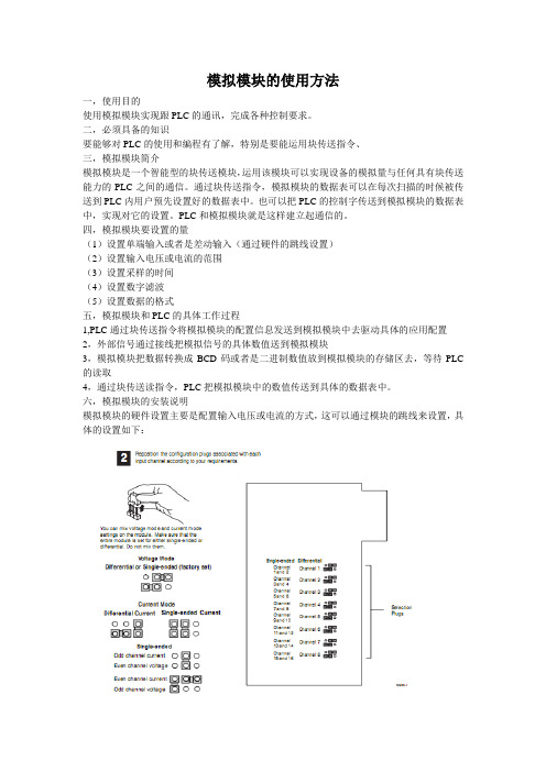
AB PLC5模拟模块的使用方法
模拟模块的使用方法一,使用目的使用模拟模块实现跟PLC的通讯,完成各种控制要求。
二,必须具备的知识要能够对PLC的使用和编程有了解,特别是要能运用块传送指令、三,模拟模块简介模拟模块是一个智能型的块传送模块,运用该模块可以实现设备的模拟量与任何具有块传送能力的PLC之间的通信。
通过块传送指令,模拟模块的数据表可以在每次扫描的时候被传送到PLC内用户预先设置好的数据表中。
也可以把PLC的控制字传送到模拟模块的数据表中,实现对它的设置。
PLC和模拟模块就是这样建立起通信的。
四,模拟模块要设置的量(1)设置单端输入或者是差动输入(通过硬件的跳线设置)(2)设置输入电压或电流的范围(3)设置采样的时间(4)设置数字滤波(5)设置数据的格式五,模拟模块和PLC的具体工作过程1,PLC通过块传送指令将模拟模块的配置信息发送到模拟模块中去驱动具体的应用配置2,外部信号通过接线把模拟信号的具体数值送到模拟模块3,模拟模块把数据转换成BCD码或者是二进制数值放到模拟模块的存储区去,等待PLC 的读取4,通过块传送读指令,PLC把模拟模块中的数值传送到具体的数据表中。
六,模拟模块的安装说明模拟模块的硬件设置主要是配置输入电压或电流的方式,这可以通过模块的跳线来设置,具体的设置如下:七,外部设备的接线方法外设模块的接线方法主要是根据变送器的不同类型(如两线式或者是四线式)的不同接法来接线的。
具体接法如下:两线式接法:四线式接法:八,模块的编程:对模拟模块的编程主要是把数据通过块传送指令发到模拟模块的配置表中或者从模块存储区中把数据读到用户配置的区域。
这里主要的方法一个是块传送指令的使用,一个是配置表和反馈表的用法。
配置表的主要数据如下:反馈表的各个数值说明:。
信捷PLC培训5-基础指令

Wy
信以致远捷行弘毅
基本指令
指令块折叠指令GROUP、GROUPE
GROUP和GROUPE指令无目标原件,使用方法是在折叠
语段的开始部分输入GROUP指令,在折叠语段的结束部分输 入GROUPE指令。 GROUP和GROUPE指令必须成对使用。该组指令并不具 有实际意义,仅是对程序的一种结构优化,因此该组指令添加 与否,并不影响程序的运行效果。
基本指令应用6
(二)程序设计
X0 出口1按钮 X1 出口2按钮 X2 出口3按钮 ALT Y0 景观灯
LDP
X0
ORP
ORP ALT
X1
X2 Y0
Wy
信以致远捷行弘毅
基本指令
脉冲输出指令PLS、PLF
程序举例
X0
LD
PLS M0
X0 M0
PLS
X1
---------------------PLF M1
Wy
信以致远捷行弘毅
基本指令应用6
某广场有三个出入口,每个出入口装有控制按钮,广
场中央有一大型景观灯,每一个按钮都可以控制其亮灭。
试设计PLC程序。
Wy
信以致远捷行弘毅
基本指令应用6
(一)分配I/O地址
SB1 SB2
X0 X1
Y0
SB2
X2
PLC
LP
~
AC220V COM COM0
Wy
信以致远捷行弘毅
图的最左边;
LD
LD OUT OR
LD OR
AND OUT
ANB
Wy
信以致远捷行弘毅
编程规则
4、串联回路相并联时应尽量放在梯形图上边;
LD OUT LD AND ORB
K5 PLC硬件使用手册201908
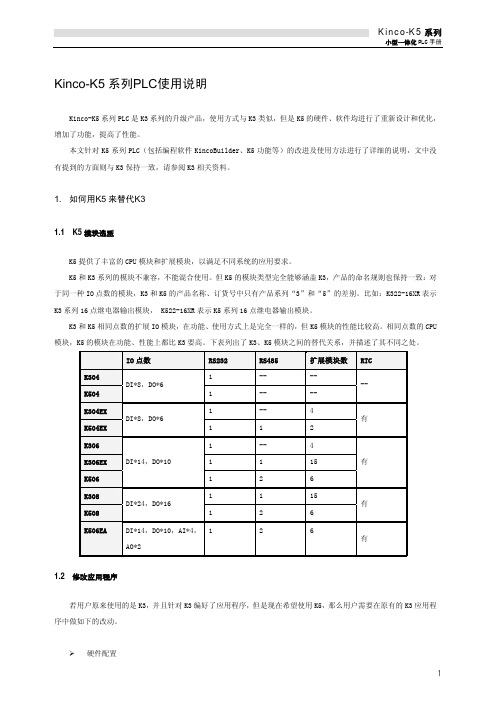
目录第一部分 (6)第一章系统通用说明 (7)1.1产品应用范围 (7)1.2本文常用名称 (7)1.3产品命名规则 (9)1.3.1产品名称说明 (9)1.3.2订货号说明 (12)1.4K INCO-K5系列PLC产品列表 (13)第二部分 (16)第一章KINCO-K5系列PLC应用 (17)1.1产品体系结构 (17)1.1.1概述 (17)1.1.2单机最大规模 (17)1.1.3通讯网络 (18)1.2系统电源设计 (19)1.2.1集成电源概述 (19)1.2.2DC24V输出电源核算 (19)1.2.3扩展电源核算 (20)1.2.4CPU模块输入功率 (21)1.3正常的工作条件 (22)第二章CPU原理及应用 (23)2.1概述 (23)2.1.1部件结构图 (23)12.2各部分功能介绍 (25)2.2.1CPU状态及指示灯 (25)2.2.2串行通信口 (26)2.2.3数据保持和数据备份 (26)2.2.4实时时钟(RTC) (27)2.2.5高速脉冲计数和高速脉冲输出 (27)2.2.6边沿中断 (27)2.3接线图 (28)2.4技术数据 (38)第三章DI扩展模块 (41)3.1DI8×DC24V (41)3.1.1接线图 (41)3.1.2技术数据 (42)3.2DI16×DC24V (43)3.2.1接线图 (43)3.2.2技术数据 (44)第四章DO扩展模块 (45)4.1DO8×DC24V (45)4.1.1接线图 (45)4.1.2技术数据 (46)4.2DO8×继电器 (47)4.2.1接线图 (47)4.2.2技术数据 (48)4.3DO16×DC24V (49)4.3.1接线图 (49)24.4DO16×继电器 (51)4.4.1接线图 (51)4.4.2技术数据 (52)第五章DI/O扩展模块 (53)5.1DI/O,DI4×DC24V DO4×DC24V (53)5.1.1端子接线图 (53)5.1.2技术数据 (54)5.2DI/O,DI4×DC24V DO4×继电器 (55)5.2.1端子接线图 (55)5.2.2技术数据 (56)5.3DI/O,DI8×DC24V DO8×DC24V (57)5.3.1端子接线图 (57)5.3.2技术数据 (58)5.4DI/O,DI8×DC24V DO8×继电器 (59)5.4.1端子接线图 (59)5.4.2技术数据 (60)第六章AI扩展模块 (61)6.1AI4×IV,电流/电压输入 (61)6.1.1端子接线图 (61)6.1.2测量范围和测量值表示格式 (61)6.1.3技术数据 (62)6.2AI4×RD,热电阻输入 (63)6.2.1端子接线图 (63)6.2.2测量范围和测量值表示格式 (63)6.2.3技术数据 (64)36.3.1端子接线图 (65)6.3.2测量范围和测量值表示格式 (65)6.3.3技术数据 (66)第七章AO扩展模块 (67)7.1AO2×IV,电流/电压输出 (67)7.1.1端子接线图 (67)7.1.2输出范围和输出值表示格式 (67)7.1.3技术数据 (68)第八章AI/O扩展模块 (69)8.1AI/O,AI2×IV AO2×IV,电流/电压输入/输出 (69)8.1.1端子接线图 (69)8.1.2AI测量范围和测量值表示格式 (70)8.1.3AO输出范围和输出值表示格式 (70)8.1.4技术数据 (71)第九章扩展功能模块 (72)9.1K541CAN通信模块 (72)9.1.1主要特点 (72)9.1.2端子和指示灯说明 (73)9.1.3接线示意图 (74)9.1.4技术数据 (74)9.2PS580扩展电源模块 (75)9.2.1主要特点 (75)9.2.2PS580使用示意图 (76)9.2.3PS580应用示例 (76)9.2.4技术数据 (78)4第十章安装及接线 (79)10.1模块外形尺寸 (79)10.2模块的连接 (80)10.3模块的安装 (81)10.4接线端子的拆卸和安装 (83)10.4.1端子排的拆卸 (83)10.4.2端子排的重新安装 (83)10.5保护电路和接地 (84)10.5.1晶体管型DO通道的保护功能 (84)10.5.2继电器型DO通道的外部保护指南 (84)10.5.3接地 (85)5第一部分通用说明6第一章系统通用说明1.1产品应用范围按照公认的PLC分类规则,Kinco-K5系列PLC属于小型一体化PLC,因此适用于工厂自动化领域中的机器控制和小规模过程控制。
PLC电路常用符号标示
Q——电路的开关器件
FU——熔断器
KM——接触器
KA——1、瞬时接触继电器 2、瞬时 有或无继电器 3、交流继电器
KT——延时 有或无继电器
SB——按钮开关
KA 一般是中间继电器.KM或K表示的是接触器.
KA是一种特殊的接触器(即开关)
AAT 电源自动投入装置
AC 交流电
整流器 U
可控硅整流器 UR
控制电路有电源的整流器 VC
变频器 UF
变流器 UC
逆变器 UI
电动机 M
异步电动机 MA
同步电动机 MS
直流电动机 MD
绕线转子感应电动机 MW
鼠笼型电动机 MC
电动阀 YM
电磁阀 YV
防火阀 YF
排烟阀 YS
DC 直流电
FU 熔断器
G 发电机
M 电动机
HG 绿灯
HR 红灯
HW 白灯
HP 光字牌
K 继电器
KA(NZ) 电流继电器(负序零序)
KD 差动继电器
KF 闪光继电器
KH 热继电器
KM 中间继电器
KOF 出口中间继电器
KS 信号继电器
KT 时间继电器
频率表 PF
相位表 PPA
最大需量表(负荷监控仪) PM
功率因数表 PPF
有功功率表 PW
无功功率表 PR
无功电流表 PAR
声信号 HA
光信号 HS
指示灯 HL
红色灯 HR
绿色灯 HG
黄色灯 HY
蓝色灯 HB
白色灯 HW
台达PLC MODRW指令
H10 K 16 K 16 K 16 K8 K8 K 16
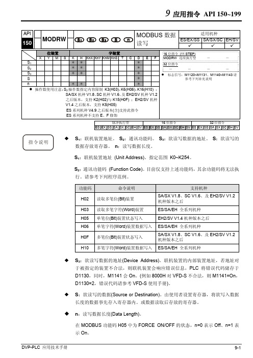
本指令于程序中使用次数并无限制,但是同时间仅有 1 个指令被执行。
功能码 K3(H03):读取多笔寄存器数据。 1. PLC 与 VFD-S 系列变频器联机 (M1143=Off 时,ASCII Mode) 2. PLC 与 VFD-S 系列变频器联机 (M1143=On 时,RTU Mode)
当在 RTU 模式时,接收数据以 HEX 数值形式储存于使用者指定 D0 开始的寄存 器内。
在 ASCII 模式或 RTU 模式,PLC 都会将要传送出的数据存放在传送数据暂存区 D1256~D1295 内,使用者若有需要可将此暂存区数据以 MOV、DMOV 或 BMOV 三个指令搬移到一般寄存器内使用。ES/EX/SS 系列机种其它指令功能对此区数 据无效。
D1296=H0100
PLC 自动将 ASCII 码转 地址 2101 H 的内容 换为数值储存于
D1297=H1766
PLC 自动将 ASCII 码转 地址 2102 H 的内容 换为数值储存于
D1298=H0000
PLC 自动将 ASCII 码转 地址 2103 H 的内容 换为数值储存于
D1299=H0000
功能码 H02 H03 H05 H06 H0F H10
命令说明 读取多笔位(Bit)装置 读取多笔字符(Word)装置 单笔位(Bit)装置状态写入 单笔字符(Word)装置数据写入 多笔位(Bit)装置状态写入 多笔字符(Word)装置数据写入
支持机种
SA/SX V1.8、SC V1.6、及 EH2/SV V1.2 机种版本之后
DATA
‘0’
30 H
‘1’
31 H
PLC5系统应用简介

PLC5系统应用简介一、PLC5系统概述PLC5(可编程逻辑控制器)是一种用于工业控制系统的计算机控制系统。
它通常被用于控制工厂中的各种自动化设备,如生产线、机器人和其他工业设备。
PLC5系统由中央处理器、输入/输出模块、通信模块和编程软件等部分组成,可以实现对工艺过程的实时监控和自动控制。
二、PLC5系统的特点1.可靠性高:PLC5系统采用模块化设计,故障率低,具有较强的抗干扰能力,保证了工业生产的稳定性和可靠性。
2.灵活性强:PLC5系统支持多种通信协议和编程语言,能够满足不同工业场景的需求,具有较强的灵活性。
3.易于维护:PLC5系统的硬件模块可直接替换和升级,编程软件简单易用,方便工程师对系统进行维护和升级。
4.成本低廉:相对于传统的硬件控制系统,PLC5系统具有成本低、安装方便的优势,适合中小型企业使用。
三、PLC5系统的应用领域PLC5系统广泛应用于各种工业控制领域,如汽车制造、化工、电力、食品加工等。
具体应用包括但不限于以下几个方面:1.生产线控制:PLC5系统可以实现对生产线各个环节的控制和协调,提高生产效率和质量。
2.过程控制:PLC5系统可以监控和控制工艺过程中的参数,实现对温度、压力、流量等参数的精确调控。
3.机器人控制:PLC5系统可以为工厂中的机器人提供精确的控制指令,实现自动化操作和生产。
4.设备安全:PLC5系统还可以用于设备安全控制,实现对设备的状态监测和异常处理,确保工作场所的安全。
四、PLC5系统在工业自动化中的作用PLC5系统在工业自动化中扮演着至关重要的角色。
它可以实现工厂生产过程的自动化控制,提高生产效率、降低生产成本,同时提高产品质量和可靠性。
通过PLC5系统的应用,工业企业可以实现数字化转型,提升竞争力,实现可持续发展。
五、PLC5系统的未来发展趋势随着工业4.0时代的到来,PLC5系统也在不断进行创新和升级。
未来,PLC5系统将更加智能化、网络化,支持更多的外部设备接入和数据交互。
Kinco步科PLCkinckk5系列编程软件用户手册英文高清版
ContentsCONTENTS (1)CHAPTER I WELCOME TO USE KINCOBUILDER (10)1.1O VERVIEW (10)1.2G ENERAL D ESIGNATION IN THE M ANUAL (11)CHAPTER II HOW TO USE KINCOBUIL DER ... A QUICK GUIDE. (14)2.1C OMPUTER R EQUIREMENTS (14)2.1.1 Minimum hardware requirements to run KincoBuilder: (14)2.1.2 Minimum Software requirements to run KincoBuilder: (14)2.2U SER I NTERFACE OF K INCO B UILDER (16)2.3U SING K INCO B UILDER TO C REATE P ROGRAMS FOR Y OUR A PPLICATIONS (18)2.3.1 Project Components (18)2.3.2 Where to store the Project Files (19)2.3.3 Importing and Exporting a Project (19)2.4H OW T HE CPU E XECUTES I TS T ASKS IN A S CAN C YCLE? (22)2.5H OW TO CONNECT THE COMPUTER WITH THE K INCO-K5 (24)2.6H OW TO MODIFY THE CPU‟S COMMUNICATION PARAMETERS (27)2.7E XAMPLE:C OMMON S TEPS TO C REATE A P ROJECT (28)CHAPTER III CONCEPTS FOR PROGRAMMING (36)3.1POU(P ROGRAMME O RGNIZATION U NIT) (36)3.2D ATA T YPES (38)3.3I DENTIFIERS (40)3.3.1 How to define an identifier (40)3.3.2 Use of Identifiers (40)3.4C ONSTANT (41)3.5V ARIABLES (43)3.5.1 Declaration (43)3.5.2 Declaring Variables in KincoBuilder (44)3.5.3 Checking Variables (44)3.6H OW TO A CCESS PLC M EMORY (45)3.6.1 Memory Types and Characteristics (45)3.6.2 Direct Addressing (47)3.6.3 Indirect Addressing (54)3.6.4 Memory Address Ranges (56)3.6.5 Function Block and Function Block Instance (58)3.6.6 Using FB Instances (60)3.6.7 FB Instances Memory Ranges (62)CHAPTER IV HOW TO USE KINCOBUIL DER ... BASIC FUNCTION S (63)4.1C ONFIGURING G ENERAL S OFTWARE O PTIONS (63)4.2A BOUT D OCKING W INDOWS (65)4.3C ONFIGURING H ARDWARE (66)4.3.1 How to open the Hardware window (67)4.3.2 Copy and paste the hardware configuration in different projects (67)4.3.3 Add/Remove Modules (67)4.3.4 Configuring Module Parameters (68)4.4T HE I NITIAL D ATA T ABLE (77)4.4.1 Opening the Initial Data Table (77)4.4.2 Editing a Cell (77)4.4.3 Making Initial Data Assignments (78)4.4.4 Editing the Initial Data Table (78)4.5T HE G LOBAL V ARIABLE T ABLE (79)4.5.1 Opening the Global Variable Table (80)4.5.2 Declaring the Global Variables (80)4.6T HE C ROSS R EFERENCE T ABLE (82)4.6.1 Opening the Cross Reference Table (82)4.6.2 The Pop-up Menu (83)4.7T HE S TATUS C HART (84)4.7.1 Opening the Status Chart (86)4.7.2 Monitoring the Variable Value (86)4.7.3 The Force Function (86)4.7.4 Right-click Menu (87)4.7.5 Force and Cancel Force (87)4.8P ASSWORD P ROTECTION (89)4.8.1 Protection Privileges (89)4.8.2 How to change the password and the protection level (89)4.8.3 How to recover from a lost password (91)CHAPTER V HOW TO US E KINCOBUILDER ... PRO GRAMMING (92)5.1P ROGRAMMING IN IL (92)5.1.1 Overview (92)5.1.2 Rules (93)5.1.3 The IL Editor in KincoBuilder (95)5.1.4 Converting IL Program to LD Program (98)5.1.5 Debug and Monitor the Program (98)5.2P ROGRAMMING IN LD (101)5.2.1 Overview (101)5.2.2 Network (101)5.2.3 Standardized graphic symbols (101)5.2.4 The LD Editor in KincoBuilder (104)5.2.5 Monitoring and Debugging the Program (111)CHAPTER VI KINCO-K5 INSTRUCTION SET (114)6.1S UMMARY (114)6.2B IT L OGIC I NSTRUCTIONS (115)6.2.1 Standard Contact (115)6.2.2 Immediate Contact (119)6.2.3 Coil (121)6.2.4 Immediate Coil (123)6.2.5 Set And Reset Coil (124)6.2.6 Set and Reset Block Coil (126)6.2.7 Set And Reset Immediate Coil (128)6.2.8 Edge detection (129)6.2.9 NCR (NOT) (131)6.2.10 Bistable elements (132)6.2.11 ALT (Alternate) (135)6.2.12 NOP (No Operation) (137)6.2.13 Bracket Modifier (138)6.3M OVE I NSTRUCTIONS (140)6.3.1 MOVE (140)6.3.2 BLKMOVE (Block Move) (141)6.3.3 FILL (Memory Fill) (144)6.3.4 SWAP (145)6.4C OMPARE I NSTRUCTIONS (148)6.4.1 GT (Greater Than) (148)6.4.2 GE (Greater than or Equal to) (150)6.4.3 EQ (Equal to) (152)6.4.4 NE (Not Equal to) (154)6.4.5 LT (Less than) (156)6.4.6 LE (Less than or Equal to) (158)6.5L OGICAL O PERATIONS (160)6.5.1 NOT (160)6.5.2 AND (162)6.5.3 ANDN (164)6.5.4 OR (166)6.5.5 ORN (168)6.5.6 XOR (Exclusive OR) (170)6.6S HIFT/R OTATE I NSTRUCTIONS (172)6.6.1 SHL (Shift left) (172)6.6.2 ROL (Rotate left) (174)6.6.3 SHR (Shift right) (176)6.6.4 ROR (Rotate right) (178)6.6.5 SHL_BLK (Bit String Shift Left) (180)6.6.6 SHR_BLK (Bit String Shift Right) (182)6.7C ONVERT I NSTRUCTIONS (185)6.7.1 DI_TO_R (DINT To REAL) (185)6.7.2 R_TO_DI (REAL To DINT) (186)6.7.3 B_TO_I ( BYTE To INT ) (188)6.7.4 I_TO_B ( INT To BYTE ) (189)6.7.5 DI_TO_I ( DINT To INT ) (192)6.7.6 I_TO_DI ( INT To DINT ) (194)6.7.7 BCD_TO_I ( BCD To INT ) (195)6.7.8 I_TO_BCD (INT To BCD ) (196)6.7.9 I_TO_A ( INT To ASCII ) (199)6.7.10 DI_TO_A ( DINT To ASCII ) (201)6.7.11 R_TO_A ( REAL To ASCII ) (203)6.7.12 H_TO_A ( Hexadecimal To ASCII ) (206)6.7.13 A_TO_H ( ASCII to Hexadecimal ) (208)6.7.14 ENCO (Encoding) (210)6.7.15 DECO (Decoding) (212)6.7.16 SEG ( 7-segment Display) (214)6.7.17 TRUNC (Truncate) (215)6.8N UMERIC I NSTRUCTIONS (217)6.8.1 ADD and SUB (217)6.8.2 MUL and DIV (219)6.8.3 MOD (Modulo-Division) (221)6.8.4 INC and DEC (223)6.8.5 ABS (Absolute Value) (225)6.8.6 SQRT (Square Root) (226)6.8.7 LN (Natural Logarithm), LOG (Common Logarithm) (227)6.8.8 EXP(Exponent with the base e) (228)6.8.9 SIN (sine), COS (cosine), TAN (tangent) (229)6.8.10 ASIN (arc-sine), ACOS (arc-cosine), ATAN (arc-tangent) (231)6.9P ROGRAM C ONTROL (233)6.9.1 LBL and JMP Instructions (233)6.9.2 Return Instructions (235)6.9.3 CAL(Call a subroutine) (237)6.9.4 FOR/NEXT ( FOR/NEXT Loop) (240)6.9.5 END (Terminate the scan cycle) (243)6.9.6 STOP (Stop the CPU) (244)6.9.7 WDR (Watchdog Reset) (245)6.10I NTERRUPT I NSTRUCTIONS (246)6.10.1 How the Kinco-K5 handles Interrupt Routines (246)6.10.2 Interrupt Priority and Queue (246)6.10.3 Types of Interrupt Events Supported by the Kinco-K5 (246)6.10.4 Interrupt Events List (247)6.10.5 ENI (Enable Interrupt), DISI (Disable Interrupt) (248)6.10.6 ATCH and DTCH Instructions (249)6.11C LOCK I NSTRUCTIONS (253)6.11.1 Adjusting the RTC online (253)6.11.2 READ_RTC and SET_RTC (254)6.11.3 RTC_R (256)6.11.4 RTC_W (258)6.12C OMMUNICATION I NSTRUCTIONS (261)6.12.1 Free-protocol Communication (261)6.12.2 XMT and RCV (261)6.12.3 Modbus RTU Master Instructions (271)6.12.4 SDO (277)6.12.5 CAN Communication Command (283)6.13C OUNTERS (292)6.13.1 CTU (Up Counter) and CTD (Down Counter) (292)6.13.2 CTUD (Up-Down Counter) (295)6.13.3 High-speed Counter Instructions (297)6.13.4 High-speed Pulse Output Instructions (313)6.14T IMERS (329)6.14.1 The resolution of the timer (329)6.14.2 TON (On-delay Timer) (329)6.14.3 TOF (Off-delay Timer) (331)6.14.4 TP (Pulse Timer) (333)6.15PID (336)6.16P OSITION C ONTROL (341)6.16.1 Model (341)6.16.2 The correlative variables (342)6.16.3 PHOME (Homing) (344)6.16.4 P ABS (Moving Absolutely) (347)6.16.5 PREL (Moving Relatively) (349)6.16.6 PJOG (Jog) (353)6.16.7 PSTOP (Stop) (355)6.16.8 PFLO_F (356)6.16.9 Examples (358)6.17A DDITIONAL I NSTRUCTIONS (369)6.17.1 LINCO( Linear Calculation ) (369)6.17.2 CRC16 ( 16-Bit CRC ) (371)6.17.3 SPD (Speed detection) (373)APPENDIX A COMMUNICA TE USING MODBUS RTU PROTOCOL (375)1.PLC M EMORY A REA (375)1.1 Accessible Memory Areas (375)1.2 Modbus Register Number (375)2.B ASIC R EPORT F ORMAT OF M ODBUS RTU (378)2.1 Modbus RTU (378)2.2 CRC Verification Algorithm in Modbus Protocol (381)APPENDIX B DYNAMIC MODIFICATION PARAMETER OF RS485 COMMUNICA TION PORT (385)1.G ENERAL D ESCRIPTION (385)2.R EGISTER I NSTRUCTION (386)3.I NSTRUCTIONS (389)4.E XAMPLE (391)APPENDIX C DA TA BACKUP (393)APPENDIX D ERROR DIAGNOSE (394)1.E RROR L EVEL (394)2.E RROR CODES (396)3.H OW TO R EAD E RRORS O CCUR B EFORE (399)4.E RROR R EGISTER (401)APPENDIX E DEFINITION OF SM AREA (404)1.SMB0: SYSTEM STATUS BYTE (404)2.SMB2: SYSTEM CONTROL BYTE (405)3.C OMMUNICATION P ORT R ESET (406)4.O THER FUNCTIONAL VARIABLES (408)5.SMD12 AND SMD16:T IMER I NTERRUPTION C YCLE (409)Chapter I Welcome to Use KincoBuilder1.1OverviewIEC61131-3 is the only global standard for industrial control programming. Its technical implications are high, leaving enough room for growth and differentiation. It harmonizes the way people design and operate industrial controls by standardizing the programming interface. IEC 61131-3 has a great impact on the industrial control industry, and it is accepted as a guideline by most PLC manufacturers. With its far-reaching support, it is independent of any single company.KincoBuilder is the programming software for Kinco-K5 series Micro PLC, and it's a user-friendly and high-efficient development system with powerful functions.KincoBuilder is developed independently and accords with the IEC61131-3 standard. It becomes easy to learn and use because many users have acquired most of the programming skills through different channels.KincoBuilder is provided with the following features:Accords with the IEC61131-3 standardSupports two standard programming languages, i.e. IL (Instruction List) and LD (Ladder Diagram)Powerful instruction set, build-in standard functions, function blocks and other special instructionsSupports structured programmingSupports interrupt service routinesSupports subroutinesSupports direct represented variables and symbolic variables, easy to develop and manage the user project.User-friendly and high-efficient environmentFlexible hardware configuration, you can define all types of the hardware parameters1.2General Designation in the Manual▪ Micro PLC (Programmable Logic Controller)According to the general classification rules, micro PLC generally refers to the type of PLC with the control points below 128. This type of PLC usually adopts compact structure, that is, a certain number of I/O channels, output power supply, high-speed output/input and other accessories are integrated on the CPU module.▪ CPU bodyNamely, the CPU module, it‟s the core of the control system. The user program is stored in the internal storage of the CPU module after being downloaded through the programming software, and will be executed by the CPU.Meanwhile, it also executes the CPU self-test diagnostics: checks for proper operation of the CPU, for memory areas, and for the status of any expansion modules.▪ Expansion module & expansion busThe expansion module is used to extend the functions of the CPU body and it is divided into expansion I/O module (to increase the input/output channels of the system) and expansion functional module (to expend the functions of CPU).The expansion bus connects the CPU and expansion modules, and the 16-core flat cable is adopted as the physical media. The data bus, address bus and the expansion module‟s working power supply are integrated into the expansion bus.▪ KincoBuilderThe programming software for Kinco-K5 series PLC, accords with IEC61131-3 standard KincoBuilder,presently provides LD and IL languages for convenience and efficiency in developing the control programs for your applications. KincoBuilder provides a user-friendly environment to develop and debug the programs needed to control your applications.▪ CPU firmwareIt is the “operating system”of the CPU module, and is stored in the Flash memory. At power on, it starts operation to manage and schedule all the tasks of the CPU module.▪ User programIt‟s also called user project or application program, the program written by the user to execute some specific control functions. After the user program is downloaded to the CPU module, it is stored in the FRAM. At power on, the CPU module shall read it from FRAM into RAM to execute it.▪ Main program and Scan CycleThe CPU module executes a series of tasks continuously and cyclically, and we call this cyclical execution of tasks as scan.The main program is the execution entry of the user program. In the CPU, the main program is executed once per scan cycle. Only one main program is allowed in the user program.▪ Free-protocol communicationThe CPU body provides serial communication ports that support the special programming protocol, Modbus RTU protocol (as a slave) and free protocols. Free-protocol communication mode allows your program to fully control the communication ports of the CPU. You can use free-protocol communication mode to implement user-defined communication protocols to communicate with all kinds of intelligent devices. ASCII and binary protocols are both supported.▪ I/O Image AreaIncluding input image area and output image area. At the beginning of a scan cycle, signal status are transferred from input channels to the input image area; at the end of a scan cycle, the values stored in the output image area are transferred to output channels;In order to ensure the consistency of data and to accelerate the program execution, the CPU module only access the image area during each scan cycle.▪ Retentive RangesThrough “Hardware” configuration in KincoBuilder, you can define four retentive ranges to select the areas of the RAM you want to retain on power loss. In the event that the CPU loses power, the instantaneous data in the RAM will be maintained by the super capacitor, and on the retentive ranges will be left unchanged at next power on. The retaining duration is 72 hours at normal temperature.▪ Data backupData backup is the activity that you write some data into E2PROM or FRAM through relevant instruction for permanent storage. Notice: Every type of permanent memory has its own expected life, for example, E2PROM allows 100 thousand of times of writing operations and FRAM allows 10 billions of times.Chapter II How to Use KincoBuilder … A Quick GuideIn this chapter, you will learn how to install KincoBuilder on your computer and how to program, connect and run your Kinco-K5 PLC. The purpose of this chapter is to give you a quick guide, and further details will be presented in the following chapter.2.1 Computer Requirements2.1.1 Minimum hardware requirements to run KincoBuilder:CPU: 1 GHz or higherHard disk space: at least 20M bytes of free spaceRAM: 512M or moreKeyboard, mouse, a serial communication port256-color VGA or higher, 1024*768 or higher2.1.2 Minimum Software requirements to run KincoBuilder:Operating system: Windows XP(32bit), Windows Vista(32bit), Windows7(32/64bit), Windows8 (32/64bit), Windows 8.1(32/64bit)Users may find errors when running KincoBuilder on OS of Windows 7 or above. Possible solutions are as follows:[COM] port in the Communication setting is nullKincoBuilder detects available COM port on a computer by reading the hardware information in the REGEDIT. In previous versions, KincoBuilder requires authorities from the Administrators to run; otherwise it shows null port lists.In the latest version, KincoBuilder will automatically detect branches. If KincoBuilder is not given authority to read port list, it will list ports from COM1 to COM9 for user to choose manually.KincoBuilder unable to run on computersUsers may turn to Compatibility Mode to run KincoBuilder and set as follows:Right click the shortcut of “KincoBuilder V1.5.x.x” and click [Properties];Click [Compatibility] in [Properties] dialogues, as shown in figure 2-1Figure 2-1 “Compatibility Mode” setting Figure 2-2 Open with SyncFail when using USB to RS232 convertor to communicate with PLCThe failure is caused by the driver programme of the convertor not compatible with the computer. Most of cases are caused with 64-bit Windows 7.Open KincoBuilder and find [Tool] →[Software Setting] →[Open Port Parallel], click “Open Port with Sync” and click “OK”. See figure 2-2.Afterwards KincoBuilder will open ports with sync and in most cases will successfully work.2.2 User Interface of KincoBuilderThe user interface uses standard Windows interface functionality along with a few additional features to make your development environment easy to use.Figure 2-1 User Interface of KincoBuilder▪Menu: It contains all the operation commands in KincoBuilder.▪Toolbar: It provides easy mouse access to the most frequently used operation commands.▪Statusbar: It provides status information and prompts for the operations.▪Manager: The Manager window provides a tree view of all project objects, including PROGRAM, Hardware,Global Variable, etc, and this can assist you in understanding the structure of the project. The project manager is a convenient tool for program organization and project management. A context menu will pop up when you right click on any tree node.▪Editor: It includes the Variable Table and the Program Editor (IL or LD). You can programming in the Program Editor and declare the local variables and input/output parameters of the POU in the Variable Table.▪Instructions: LD instruction set and IL instruction set. Here a tree view of all the available instructions is provided.▪Output: The Output Window displays several types of information. Select the tab at the base of the window to view the respective information: the “Compile”window displays the latest compiling information and the “Common” window displays some information concerning the latest operations.2.3 Using KincoBuilder to Create Programs for Your Applications2.3.1 Project ComponentsIn this manual, a user program and a user project have the same meaning.While programming for a specific application, you need to configure the controllers used in your control system, define symbolic variables and write all kinds of POUs, etc. In KincoBuilder, all of these data (including POUs, hardware configuration, global variables, etc.) are organized to structure a user project. You can manage the project information consistently and easily.The components of a project are described in the following table. The items marked with “Optional” are not essential components in the project, so you can ignore them.Table 2-1 Project Components2.3.2 Where to store the Project FilesWhen creating a project, KincoBuilder firstly ask you to specify a full path for the project file, and then an empty project file (with the ".kpr" extension) shall be created and saved in this path. In addition, a folder with the same name as the project shall be also created in this path; this folder is used to store all the program files, variable files and other temporary files of the project.For example, if you create a project named “example” in “c:\temp” directory, the project file path is“c:\temp\example.kpr”, and other files are stored in the “c:\temp\example” folder.2.3.3 Importing and Exporting a ProjectKincoBuilder provides [File]>[Import…] and [File]>[Export…] menu commands for you to backup and manage a project.[Export…]Compress all the files related to the current project into one backup file (with the “.zip” extension). Select the [File]> [Export…] menu command.The dialog box “Export Project…” appears, as shown in Figure 2-2.Figure 2-2 Export the ProjectSelect the path and enter the filename, then click [Save].The backup file for the current project shall be created.[Import…]Import a project from an existing backup file (with the extension .zip) and open it.Select the [File]> [Import…] menu command.The dialog box “Import Project…” appears, as shown in Figure 2-3.Figure 2-3 Import a Project: Select a backup fileSelect a backup file, and then click [Open].The following dialog box appears for you to select the directory to save the restored project files.Figure 2-4 Import a Project: Select the destination directorySelect a directory, then click [OK], and the project files shall be restored into the selected directory, withthat the restored project shall be opened.2.4 How The CPU Executes Its Tasks in a Scan Cycle?The CPU module executes a series of tasks continuously and cyclically, and we call this cyclical execution of tasks as scan. Only can the main program and interrupt routines be executed directly in the CPU module. The main program is executed once per scan cycle; an interrupt routine is executed once only on each occurrence of the interrupt event associated with it.The CPU module executes the following tasks in a scan cycle, as shown in Figure 2-11:Figure 2-5 Scan CycleExecuting the CPU diagnostics: The CPU module executes the self-test diagnostics to check for proper operation of the CPU, for memory areas, and for the status of the expansion modules.Read the inputs: The Kinco-K5 samples all the physical input channels and writes these values to the input image areas.Executing the user program: The CPU module executes the instructions in the main program continuously and updates the memory areas.Processing communication requestsWriting to the outputs: The Kinco-K5 writes the values stored in the output areas to the physical output channels.Interrupt events may occur at any moment during a scan cycle. If you use interrupts, the CPU module willinterrupt the scan cycle temporarily when the interrupt events occur and immediately execute the corresponding interrupt routines. Once the interrupt routine has been completed, control is returned to the scan cycle at the breakpoint.Figure 2-6 Execution of Interrupt Routines2.5 How to connect the computer with the Kinco-K5The CPU module provides an integrated RS232 or RS485 serial communication port to communicate with other equipments. Here we discuss how to connect a CPU module (with RS232 port) with the computer to start programming the Kinco-K5 PLC using KincoBuilder.Launch KincoBuilder, open an existing project or create a new project;Connect the serial port of the computer with that of the CPU module with a proper programming cable. Notice: RS232 connections are not hot-swappable, so you must switch off the power supply for at least one side (the CPU module or the computer) before you connect/disconnect the cable. Otherwise, the port may be damaged.②Configure the parameters of the computer‟s serial communication port. Notice: Communications can’t be established unless the serial communication parameters of the computer’s port are identical with those of the CPU’s port.Select [Tools]>[Communications…] menu command, or double-click the [Communications] node in the Manager window, or right-click the [Communications]node and select the [Open] command on the pop-up menu, then the “Communications” dialog box appears.Figure 2-7 The “Communications ” Dialog BoxSelect the station number of the target PLC in the [Remote] list box; Select a COM port used on the computer in the [Port] list box; Configure the parameters of the selected COM port (including[Baudrate], [Parity], [Data Bits] and [Stop Bits]) according to those of the CPU‟s port, and then click [OK] button to save and apply them.If you don‟t know the communication parameters of the CPU‟s port, how to acquire them?There are two ways:Select a [Port] used on the computer, then click [Search] button to make KincoBuilder search for the parameters of the online CPU module automatically. It shall take several seconds to several minutes to complete. If the search completes successfully, KincoBuilder will automatically configure the appropriate parameters for the computer.Turn off the power supply for the CPU module; Place its operation switch at STOP position; Then turn the power supply on, and now the CPU‟s port will use the default serial communication parameters: Station number, 1; Baudrate, 19200; None parity check; 8 data bits; 1 stop bit. You can configure the computer‟sserial COM port according to these parameters. Notice: Do not change the switch’s position until you have modified the CPU’s communication parameters.After you have configured the communication parameters of the computer‟s COM port, you are ready to program the Kinco-K5 PLC.2.6 How to modify the CPU’s communication parametersAfter you have connected a CPU module with the computer, you can modify its communication parameters at will using KincoBuilder.First, open the “Hardware” window by using one of the following ways:⏹Double-click the [Hardware] node in the Manager window;⏹Right-click the [Hardware] node, and then select the [Open…] command on the pop-up menu. The upper part of the hardware window shows a detailed list of the PLC modules in table form, and we call it Configuration Table. The Configuration Table represents the real configuration; you arrange your modules in the Configuration Table just as you do in a real control system.The lower part of the hardware window shows all the parameters of the selected module in the Configuration Table, and we call it Parameters Window.Select the CPU module in the Configuration Table, and then select the [Communication Ports] tab in the Parameters Window. Now, you can modify the communication parameters here, as shown in the following figure.Figure 2-8 Communication ParametersAfter you have modified the parameters, you must download them into the CPU module. Notice: The configuration parameters won’t take effect unless they are downloaded.2.7 Example: Common Steps to Create a ProjectIn order to help the beginners to understand the Kinco-K5 quickly, in the following we‟ll use a simple example to introduce some common steps for creating and debugging a project step by step. Please refer to the related sections to know a specific function in detail in the following chapters.Assume that we shall create the following project:Project: named “Example”;Hardware: a Kinco-K506-24A T CPU module;Control logic: Toggle Q0.0---Q0.7 in turn and cyclically. For better structure, we use two POUs: a subroutine named “Demo” to realize the control logic; the Main Program named “Main” in which “Demo”is invoked.Firstly, launch KincoBuilder.If necessary, modify the defaults used in KincoBuilder by using the following way:Select the [Tools]>[Options…] menu commandThe “Options” dialog box appears, in which you can configure some defaults, e.g. the default “Programming language”, etc. These defaults will be saved automatically; and so you just need configure them once before the next modification.Default programming language is [LD Ladder Diagram].Create a new project by using one of the following ways:Select the [File]>[New project...] menu commandClick the icon in the toolbarThe “New Project…” dialog box appears. You just need to enter the project name and assign its directory, and then click [Save], the new project shall be created.For this example, let‟s select “D:\temp” as the project directory, and name the project as “Example”.Modify the hardware configuration. You can configure the hardware at any time. However, because the hardware configuration is necessary for a project, you are recommended to complete it at first.When a new project has been created, KincoBuilder will automatically add a default CPU assigned in the “Options” dialog box.You can open the “Hardware” window by using one of the following ways:⏹Double-click the [Hardware] node in the Manager window;⏹Right-click the [Hardware] node, and then select the [Open…] command on the pop-up menu. Please refer to 2.6 How to modify the CPU‟s communication parameters for detailed steps.For this example, a Kinco-K506-24A T module with the default parameters is used.Initializing dataYou may initialize the data at any time. You may assign initial values to BYTE, WORD, DWORD, INT, DINT and REAL variables in V area. Before CPU is turned power on and enters into the main loop, the initial data will be processed and the initial values assigned by the user will be valued corresponding addresses.NOTE: Any memory areas that permanently saved by orders as “initialize data”or “data maintain”will be recovered or valued after CPU enters into the main loop. They will follow a sequence: recover the memory as per defined in “data maintain”, initialize value of areas as per defined in “initialize data”, recover permanently saved data as per defined by users.Create the example programs.KincoBuilder provides IL and LD programming languages. You can select the [Project]>[IL] or [Project]>[LD] menu command to change the current POU‟s language at will.For this example, a main program named “Main”and a subroutine named “Demo”shall be written in LD language.。
K5系列PLC使用简要说明(20130624)
2.2 错误代码
代码
严重错误 20 21 25 26 27 28 29 30 35 40 41 42 60 61 62 65 66 67 70 71 72 75 76 77
描述
在“PLC 硬件配置”信息中,CPU 类型配置错误。 在“PLC 硬件配置”信息中,扩展模块错误(使用了其它系列的模块)。 上电时,读取 PLC 保护类型失败。 上电时,读取目标文件(明文)失败。 上电时,读取目标文件(密文)失败。 上电时,目标文件的 CRC 校验错误。 上电时,检查 PLC 程序中有未知指令。 上电时,检查 PLC 程序的参数个数超过限制。 上电时,读取永久存储区数据失败。 运行时,JMP 指令跳转失败。 运行时,子程序调用失败。 运行时,中断子程序调用失败。 上电时,第 1 个扩展模块超时没有响应。 上电时,第 1 个模块响应错误。 第 1 个扩展模块与硬件配置中的类型不一致。 上电时,第 2 个扩展模块超时没有响应。 上电时,第 2 个模块响应错误。 第 2 个扩展模块与硬件配置中的类型不一致。 上电时,第 3 个扩展模块超时没有响应。 上电时,第 3 个模块响应错误。 第 3 个扩展模块与硬件配置中的类型不一致。 上电时,第 4 个扩展模块超时没有响应。 上电时,第 4 个模块响应错误。 第 4 个扩展模块与硬件配置中的类型不一致。
3
80 81 22 85 86 87 95 96 97 一般错误 136 137 138 139 300 301 320 321 322 323 324 325 326 327 329 330 331 332 333 334 335 336 341 350 351 360
上电时,第 5 个扩展模块超时没有响应。 上电时,第 5 个模块响应错误。 第 5 个扩展模块与硬件配置中的类型不一致。 上电时,第 6 个扩展模块超时没有响应。 上电时,第 6 个模块响应错误。 第 6 个扩展模块与硬件配置中的类型不一致。 上电时,CPU 模块发送扩展通信报文失败。 上电时,CPU 模块扩展总线进入错误被动状态。 上电时,CPU 模块扩展总线进入总线关闭状态。
Keyence KV5000 PLC 连接指南说明书

◎Revision RecordKeyence KV5000 Ethernet此技術文件用於說明當使用觸控屏時,如何與Keyence控制器KV 5000系列產品正確進行連線以及相關設置需要注意的事項。
(適用於KV 5000 Ethernet通訊連線,本文件以KV-5000實測)1、選擇Etherner 3、選擇電腦網路卡4、開始偵測2、自動偵測5、搜尋到的PLC1、點擊KV-50002、設定PLC IP3、設定PLC PORT(預設8501)PLC 參數設定即可HMI Setting1.選擇Device/Server Setting: Keyence Corp. --- KV-5000 設定通訊設定: 預設埠為”8501”PLC Device ListBit Devices:Word Devices:~Thank You~Technical Support Information中國大陸QQ專線 : 800014850 / 資料下載專區 ftp::// + User name + Password (欲加入會員需要申請)合作貼牌聯絡專線: China: 0910011916 / 86-138******** *****************Taiwan: 886-910011915 *****************Worldwide: 886-910011914 *****************Cermate Technologies (Shanghai) Inc. 屏通科技(上海)有限公司Phone: +86-21-51758590~2FAX : +86-21-51758589E-mail: ************************Shenzhen Cermate Technologies Inc. 屏通科技(深圳)有限公司Phone: +86-755-83562179,FAX : +86-755-83562294E-mail: **********************Cermate Technologies Inc. (台湾) 屏通科技股份有限公司7F-1, No. 168, Lien-Cheng Road, Chung-Ho City, Taipei, Taiwan 235 R.O.C.Phone: 886-2-22437000FAX : 886-2-22499933E-mail: *******************。
kc5
课题:第五章PLC应用程序课型:同步教学教学目的:能灵活运用以前所讲的指令编写程序,熟练掌握PLC产品FP1的编程语言。
教学重点:PLC基本应用程序,尤其与定时器相关的程序。
教学难点:PLC高级应用程序,尤其是混合液体设备控制程序和智能控制程序。
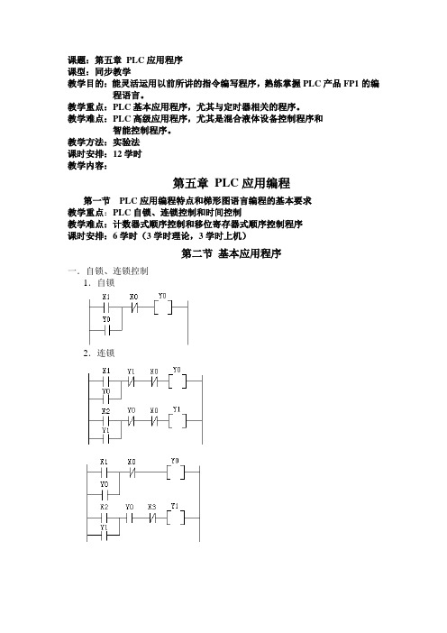
教学方法:实验法课时安排:12学时教学内容:第五章PLC应用编程第一节PLC应用编程特点和梯形图语言编程的基本要求教学重点:PLC自锁、连锁控制和时间控制教学难点:计数器式顺序控制和移位寄存器式顺序控制程序课时安排:6学时(3学时理论,3学时上机)第二节基本应用程序一.自锁、连锁控制1.自锁2.连锁二.时间控制1.延时断开控制2.闪烁控制3.长延时控制三.顺序控制1.连锁式顺序步进控制2.定时器式顺序控制3.计数器式顺序控制4.移位寄存器式顺序控制1.用步进指令进行顺序控制教学重点:单按钮控制电动机的启动和报警控制程序。
教学难点:混合液体设备控制程序和智能控制程序。
课时安排:6学时(3学时理论,3学时上机,其中最后两节上总复习)第三节PLC 应用编程一.三地控制电动机的启停二.单按钮控制电动机的启动三.报警控制。
要求:当报警开关S1闭合时,要求报警。
警灯闪烁,警铃响。
开关S2为报警响应开关。
当S2接通时,报警灯从闪烁变常。
同时报警铃关闭。
开关S3为警灯测试开关,S3接通,则警灯亮。
四.三地控制一盏灯。
五.行程控制六.顺序启动,逆序停止控制七.流水灯控制八.混合液体设备的控制九.智能控制。