文献翻译-盘式制动器的应用
盘式制动器中英文对照外文翻译文献
中英文对照外文翻译文献(文档含英文原文和中文翻译)外文:An Experimental Analysis of Brake Efficiency Using fourFluids in a Disc Brake SystemABSTRACTThe paper studies disc brake failure in Mini-buses using an experimental analysis to test the maximum braking force when different brake fluids such as clean, less dirty, dirty and soapy water solution were used in the braking system. The experimental results clearly showed that the soap solution appears to be the best fluid as far as low viscosity and stability of viscosity with increase in temperature are concerned. However, the soap solution is not compatible with other fluid which makes it difficult to be substitute as a clean brake fluid. The result of the Thepra Universal Brake Testing Equipment used for the braking efficiency test indicated that a pedal brake of 117 kN produce a brake force of 0.96 kN for clean brake fluid, 0.91 kN for the less dirty, 0.85 kN for dirty and 1.44 kN forsoap solution. The value of 1.44 kN which was achieved when the soap solution was used indicated a positive braking force and the indicating that soap solution could be used to produce a high pedal force within a very short time (about 10-30 min) and can therefore be used only in case of emergency. The brake efficiency test indicated that under hot conditions the braking efficiency is reduced and the presence of air in the system renders the braking ineffective because higher pedal force was needed to be able to produce a significant braking force which is noted for causing brake failure.Keywords: Brake fade, brake failure, disc brake, efficiency, pedal force INTRODUCTIONWhen a vehicle is accelerated, energy supplied by the engine causes the vehicle’s speed to increase. Part of this energy is instantly used up in overcoming frictional and tractive resistance but a large amount of it remains stored in the vehicle. According to Heinz (1999) this energy of motion is called the kinetic energy and the existence of kinetic energy is observed when a vehicle is moving and neutral gear is selected. The vehicle does not immediately come to rest; instead it travels for a considerable distance before it becomes stationary. In this case the stored energy is used to drive the vehicle against the resistances that oppose the vehicle’s motion. Relying on these r esistances to slow down a vehicle could cause many problems, so an additional resistance called a brake is needed to convert the kinetic energy to heat energy at a faster rate in order to reduce the speed of the vehicle Mcphee and Johnson (2007). This reduces the speed of the vehicle at a faster rate and brings the vehicle to rest within the shortest possibletime when the brakes are applied.From the point of view of Johnson et al. (2003) most automotive systems in use today utilize front disc brakes, but four-wheel disc systems are also common In disc brakes, the rotor rotates with the wheel and the pads move out to rub the rotor when the brakes are applied. Most disc brakes use floating calipers. The caliper slides in and out as the brakes are applied and released. The piston moves the inside pad out and pushes the outside pad into the rotor by sliding the caliper back toward the rotor.The use of disc brakes to reduce speed or bring the vehicle to rest when in motion cannot be over emphasized if the safety of the occupant is to be guaranteed Heinz (1999). To bring a vehicle to a stop, the disc brakes have to absorb all the energy given to thevehicle by the engine and that due to the momentum of the vehicle. This energy must then be dissipated. In most vehicle disc brakes, the energy is absorbed by friction, converted into heat and the heat dissipated to the surrounding air (Thoms, 1988). As the energy is absorbed, the vehicle is slowed down; in other words, its motion is retarded. The brakes must also pull up the vehicle smoothly and in a straight line to bring the vehicle to a stop position.It is therefore very important that the disc brakes of vehicles operate with the highest efficiency. This couldreduce the rate of accidents due to brake failure so that life and property could be preserved and also to ensure that occupants of these commercial vehicles go about their normal lives without any fear of being involved in an accident. Available crash data in Ghana suggests that about 1,900 persons are killed annually in road traffic crashes (Afukaar et al., 2008) and that more than 40% of the road traffic fatalities are occupants of cars, buses and trucks. Most often than not, some of the road accidents involving commercial vehicles, such as the mini-buses have been attributed to the failure of the disc brakes. The reason for testing the viscosity of these brake fluids, especially that of the soap solution was as a result of the practice of most Ghanaian drivers sometimes using the soapy solution as a substitute to the original brake fluid in the braking system and also using dirty brake fluid which has been used for bleeding purposes. The main objective of this study which is part of a larger work seeks to investigate and establish the reasons for the disc brake failure due to brake fluid also check the efficiency of the four different types of fluids used in the transmission of braking forces. The study looked at the maximum braking force when using clean, less dirty, dirty and soapy water solution in the braking system. It also looked at the braking force when the braking system is with or without servo unit and operating under cold or hot condition with air or without air in the braking systemDISC BRAKESThe disc brake consists of an exposed disc which is attached to the hub flange; the two friction pads arepressed on to this disc to give a braking action. Figure 1a, shows the disk brake system of a car and pad that is separated from wheel assembly to better shows the disk and the pad in sliding contact. As it can be seen, typical disk brake system and caliper assembly of a solid disk brake rotor is completely noticeable. Figure 1b shows schematic form of the disk and the pad in sliding contact assembly.(a) (b)Fig. 1: Disc brakeThe pads are moved by hydraulic pistons working in cylinders formed in a caliper that is secured to a fixed part of the axle. When the hydraulic pressure is applied to the two cylinders held in the fixed caliper, the pistons move; this action forces the friction pads into contact with the rotating cast iron disc. The sandwiching action of the pads on the disc gives a retarding action and heat generated from the energy of motion is conducted to the disc.Greater part of the disc is exposed to the air; therefore heat is easily radiated, with the result that the brake can be used continuously for long periods before serious fade occurs. Since the friction pads move at a right angle to the disc, any drop in the friction value does not affect the force applied to the pad. As a result this type of brake is not less sensitive to heat (Mudd, 1972). The disc brake was developed to minimize the fade problems. When fading occurs, the driver has to apply a much larger effort and in extreme cases it becomes impossible to bring the vehicle to rest. No assistance is obtained from the rotating disc to aid the driver in the application of a disc brake to achieve a given retardation. A disc brake requires a greater pedal pressure and toachieve this pressure required the hydraulic braking system using a good quality brake fluid in its operation.The fluid used in the hydraulic braking systems is a vegetable oil with certain additives. According to Nunney et al. (1998) a good brake fluid should have the following requirements, low viscosity, high boiling point, compatibility with rubber components, lubricating properties, resistance to chemical ageing and compatibility with other fluids. However, mostGhanaian drivers sometimes used other fluid such as dirty brake fluid, less dirty fluid and even soapy water sometimes as a substituted to the original brake fluid. This study among other things will also investigate which of these brake fluid, clean, dirty, less dirty and soapy water will have the best viscosity, high boiling point and less braking force.MATERIALS AND METHODSThe design used for this study was experiment which employed the used of viscometer and Thepra Universal Automotive Brake Testing machine to check the efficiency of the four fluids in the transmission of braking forces.Laboratory analysis: The viscosity tests on the four different liquids were carried out at the Kwame Nkrumah University of Science and Technology (KNUST) Thermodynamics laboratory. The liquids were clean brake fluid, less dirty brake fluid, dirty brake fluid and soap solution. It was necessary to find out how the viscosity of different qualities of brake fluid affected braking efficiency and to find out whether there was any correlation between these and the occurrence of brake failure.Viscosity test on the various fluids used: The viscosity test was carried out on a Redwood Viscometer in Fig. 2 on the four different kinds of fluids to determine their viscosities. The apparatus consists of a vertical cylinder containing the fluid under test which was allowed to flow through a calibrated orifice situated at the centre of the cylinder base. The orifice is closed by a ball valve when it is not being used.Fig. 2: Redwood viscometer used to determine the viscosity of the fluidsThe oil cylinder is surrounded by a water jacket which maintains the lubricant under test at a required temperature by means of a Bunsen burner flame applied to the heating tube. The thermometer for the water in the jacket is mounted in a paddle-type stirrer which can be rotated by hand, using the handle (Zammit, 1987).Procedure for testing various viscosities of the fluids: To test the viscosity of a fluid, the water jacket was filled with water with the orifice ball valve in position. Fluid was poured into the cylinder to the level of the pointer. A 50 mL measuring flask was placed centrally under the orifice. The water was stirred gently until the water and fluid thermometers were the same (room temperature, 30ºC). Thetemperature was recorded. The ball valve was then raised and a stopwatch used to record the time (in seconds) for a 50 mL of fluid to flow into the measuring flask. The test was repeated with the fluid temperatures increasing by 10ºC each time up to 90ºC. All the data for the four differentfluids were recorded as shown in Table 1Thepra universal stand automotive brake testing equipment:The ThepraUniversal Stand Automotive brake testing equipment is structured in such a way that the driven part, such as brake disc, was plugged on to the motor shaft. The brake anchor plate and the caliper are fastened to a flange via a linkage of bar which is connected to the flange. The brake force is measured and displayed on a digital indicator. The individualunits are plugged into the two span-frames which are fastened to both sides. All the brake components used in the testing equipment are original vehicle components. The pedalforce is measured at the actuating linkage of the brake master cylinder and displayed on a digital indicator (Technolab, 2009)RESULTS AND DISCUSSIONExperimental results of viscosity test: Table 1 present the results of viscosity test inan experiment for the four fluids, using the Redwood Viscometer.From the test results obtained using Redwood viscometer, Viscosity-Temperature graphs for the fluids were plotted. Figure 3 shows the plot of viscosity againsttemperature of the four fluids.Table 1: Viscosity testValues of the various viscosities werecalculated using the formula:V = hfρgD232hfvwhere,V : The Viscosityhf : The capillary heightρ : The density of the fluidg : Acceleration due to gravityD : The diameter of the orificev : The velocity (Bird et al., 1960) Fig. 3: Viscosity-temperature relationship of the fluidsFrom Fig. 3 the dirty fluid has the highest viscosity followed by the less dirty fluid, clean fluid and soap solution in that order. From the results shown in Fig. 2 and theviscosity test shown in Table 1, the soap solution appear to be the best fluid as far as lowviscosity and stability of viscosity with increase in temperature are concerned. However, it is less compatible with other fluids, difficult to mix easily with other brake fluids and has a low boiling point which will not make it suitable to be substitute as clean brake fluid (Nunney et al., 1998).The clean brake fluid is next as far as viscosity and stability of viscosity with increase in temperature are concerned. On the other hand, it satisfies all the other requirements of a good fluid for the braking system given in Table 1. According to Mudd (1972) and Nunney et al. (1998), a good brake fluid should have properties such as high boiling point, compatibility with rubber components, good lubrication properties, resistance to chemical ageing (long shelf life) and compatibility with other fluids. The less dirty fluid is very unstable as far as viscosity change with temperature increase is concerned. It is therefore not very reliable in a braking system since its behavior changes as the braking system heats up. The viscosity of the dirty fluid is stable with increase in temperature, however, it is very viscous (235-178 kgs/m3 in the temperature range 30 to 90ºC). It will therefore not be good and effective in brake force transmission. From these results and literature, it is obvious that the clean brake fluid is more suitable for the transmission of braking force as it’s possess all the good brake fluid qualities.Experimental results of the disc brake system:These sections present the results and discussion of the experiments using the four fluids in a Disc brake system under different conditions. Test results for hot and cold conditions of the Disc brake system using a servo system and without using a servo system were considered.Disc brake in cold condition with and without servo unit: The result in Table 2 clearly shows the pedal force and the brake force for clean, less dirty, dirty and soap solution when using disc brake in cold condition with servo unit with the Thepra Universal Brake Testing Equipment. A pedal brake of 117 kN produce a brake force of 0.96 kN for a clean brake fluid,Table 2: Results of disc brake in cold condition with servoTable 3: Results of disc brake in hot condition with servo0.91 kN for the less dirty, 0.85 kN for dirty and 1.44 kN for soap solution. Comparatively, a maximum brake force is achieved when the fluid is clean. When there is the presence of dirt,the brake force decreases and therefore more pedal force is needed to take up thewithout servoloss created by the dirt.Hence the greater the dirt, the greater thepedal force required.The value of 1.44kN which wasachieved when the soap solution wasused indicated a positive braking force compared with all the three fluids at the same pedal force. Subsequent pedal forces applied as shown in Table 2 gave a reduction in the brake force when soap solution was used. The implication was that soap solution could be used to produce a high pedal force within a very short time (about 10-30 min) and can therefore be used in case of emergency.From Table 2, it can be observed that for the same pedal force of 117 KN the soap solution transmitted the highest amount of brake force followed by the clean fluid, less dirty fluid and dirty fluid in that order. This implies that in cold condition using servo, the soap solution performs best followed by the clean, less dirty and dirty respectively.Disc brake in hot condition with servo unit: When the experiment was carried out using a disc brake under the hot conditions with the introduction of a servo, a pedal force of 120 kN gave a brake force of 0.95 kN for clean fluid, 0.90 kN for less dirty, 0.85 kN for a dirty fluid and 0.19 KN for soap solution. The result could be explain that, the clean brake fluid gave the highest brake force follow by less dirty, dirty and soap solution. It was observed that the soap solution perform poorly at this time recording a brake force of 0.19 KN as shown in Table 3.Disc brake in hot condition without servo: Figure 4 shows a plot of disc brake inhot condition without servo unit. It can be observed that, under hot conditions for the disc brake without servo, the trend is generally the same. The soap solution performed very badly compare with the other fluids, unlike its performance under cold conditions. This may be due to evaporation of the fluid making the fluid compressible; as if air was in the braking system. Generally, the clean fluid performed best in terms of transmission of brake force followed by the less dirty, dirty and soap solution in that order.Disc brake with air in system under cold condition: Braking force for this experiment was generally low as compared with the case when air was not trapped in the system as shown in Table 4. When the experiment was conducted with a pedal force of 165 kN, braking force ofTable 4: Results of disc brake with air in system under cold condition with servoFig. 5: Results of disc brake with air in system under hot condition with servo0.32 kN soap solution was obtained, for 0.37 KN for dirty, 0.28 KN for less dirty and 0.30 kN for clean fluid. This is in line with literature because according to Mudd (1972) the presence of air in the braking system makes the system ineffective since much of the drivers effort will be used to compress the air leaving very little for the brake application.Again, the soap solution did not give the least braking force because when the system is cold, soap solution is effective and its density is higher since there is nooccurrence of evaporation of the solution.Disc brake with air in system under hot condition: The Fig. 5 shows the plot of a graph indicating disc brake with air in the system under hot condition clearly shows that, when a pedal force of 152 kN was applied, a brake force of 1.11 kN was obtained for clean, 0.37 kN for less dirty, 0.28 kN for dirty and 0.26 kN for soap solution. It was observed that the maximum brake force was attained when the fluid was clean and on the introduction of dirty fluid, the brake force reduced drastically, though the pedal force was very high at 152 kN in the hot condition.Soap solution provides the least brake force because the air content in the system increases due to evaporation and hence the pedal force compresses air rather than transmitting power. As the system heats up, the air in the system expands thereby reducing the braking efficiency which results in brake failure.CONCLUSIONThe study was conducted using an experiment performed on a Thepra Brake Testing Equipment to check the efficiency of the four fluids in the transmission of braking forces. According tothe viscometer test shown that the soap solution appears to be the best fluid as far as low viscosity and stability of viscosity with increase in temperature is concerned. However, it is less compatible with other fluids, difficult to mix easily with other brake fluids and has a low boiling point which will not make it suitable to be substituted as a clean brake fluid.Again, when air is trapped in the braking system, which results in the brake fluid being compressible, higher pedal force was needed to be able to produce a significant braking force.Also, when brakes are operated under hot conditions its efficiency is reduced, a fault known as brake fade occurs as a result of the heating up of the brakes which creates less frictional resistance between rotating disc and the frictional pads.Finally, Soap solution when used at cold condition produces high braking force but becomes less effective after prolong use due to the presence of heat which evaporates the soap solution.REFERENCESAfukaar, F., K. Agyemang, W. Ackaah and I. Mosi, 2008. Road traffic crashes inGhana, statistics 2007. Consultancy Service Report for National Road SafetyCommission of Ghana.Bird, R., S. Wright and E.N. Light, 1960. Transport Phenomena, Gibrine Publishing Company,Heinz, H., 1999. Vehicle and Engine Technology. 2nd Edn.,Butterworth-Heinemann Publications, Nurumberg, pp: 235-291Johnson, D., B. Sperandei and R. Gilbert, 2003. Analysis of the flow through a vented automotive brake rotor. J. Fluids Eng., 125: 979-986.Mcphee, A.D. and D.A. Johnson, 2007. Experimental heat transfer and flow analysis of a vented brake rotor. Int. J. Thermal Sci., 47(4): 458-467.译文:一个使用四个液体系统分析盘式制动器的制动效率的实验摘要当车辆加速时能量由发动机提供使汽车的速度增加。
关于制动器的外文文献翻译、中英文翻译、外文翻译

外文原文:THE BRAKE BIBLEBrakes - what do they do?The simple answer: they slow you down.The complex answer: brakes are designed to slow down your vehicle but probably not by the means that you think. The common misconception is that brakes squeeze against a drum or disc, and the pressure of the squeezing action is what slows you down. This in fact is only part of the equation. Brakes are essentially a mechanism to change energy types. When you're travelling at speed, your vehicle has kinetic energy. When you apply the brakes, the pads or shoes that press against the brake drum or rotor convert that energy into thermal energy via friction. The cooling of the brakes dissipates the heat and the vehicle slows down. It's the First Law of Thermodynamics, sometimes known as the law of conservation of energy. This states that energy cannot be created nor destroyed, it can only be converted from one form to another. In the case of brakes, it is converted from kinetic energy to thermal energy.Angular force. Because of the configuration of the brake pads and rotor in a disc brake, the location of the point of contact where the friction is generated also provides a mechanical moment to resist the turning motion of the rotor.Thermodynamics, brake fade and drilled rotors.If you ride a motorbike or drive a race car, you're probably familiar with the term brake fade, used to describe what happens to brakes when they get too hot. A good example is coming downa mountain pass using your brakes rather than your engine toslow you down. As you start to come down the pass, the brakes on your vehicle heat up, slowing you down. But if you keep using them, the rotors or drums stay hot and get no chance to cool off. At some point they can't absorb any more heat so the brake pads heat up instead. In every brake pad there is the friction material that is held together with some sort of resin and once this starts to get too hot, the resin starts to vapourise, forming a gas. Because the gas can't stay between the pad and the rotor, it forms a thin layer between the two whilst trying to escape. The pads lose contact with the rotor, reducing the amount of friction and voila. Complete brake fade.The typical remedy for this would be to get the vehicle to a stop and wait for a few minutes. As the brake components cool down, their ability to absorb heat returns and the next time you use the brakes, they seem to work just fine. This type of brake fade was more common in older vehicles. Newer vehicles tend to have less outgassing from the brake pad compounds but they still suffer brake fade. So why? It's still to do with the pads getting too hot. With newer brake pad compounds, the pads transfer heat into the calipers once the rotors are too hot, and the brake fluid starts to boil forming bubbles in it. Because air is compressible (brake fluid isn't) when you step on the brakes, the air bubbles compress instead of the fluid transferring the motion to the brake calipers. Voila. Modern brake fade.So how do the engineers design brakes to reduce or eliminate brake fade? For older vehicles, you give that vapourised gas somewhere to go. For newer vehicles, you find some way to cool the rotors off more effectively. Either way you end up with cross-drilled or grooved brake rotors. While grooving the surface may reduce the specific heat capacity of the rotor, its effect is negligible in the grand scheme of things. However, under heavy braking once everything is hot and the resin is vapourising, the grooves give the gas somewhere to go, so the pad can continue to contact the rotor, allowing you to stop.The whole understanding of the conversion of energy is critical in understanding how and why brakes do what they do, and why they are designed the way they are. If you've ever watched Formula 1 racing, you'll see the front wheels have huge scoops inside the wheel pointing to the front (see the picture above). This is to duct air to the brake components to help them cool off because in F1 racing, the brakes are used viciously every few seconds and spend a lot of their time trying to stay hot. Withoutsome form of cooling assistance, the brakes would be fine for the first few corners but then would fade and become near useless by half way around the track.Rotor technology.If a brake rotor was a single cast chunk of steel, it would have terrible heat dissipation properties and leave nowhere for t he vapourised gas to go. Because of this, brake rotors are typically modified with all manner of extra design features to help them cool down as quickly as possible as well as dissapate any gas from between the pads and rotors. The diagram here shows some examples of rotor types with the various modification that can be done to them to help them create more friction, disperse more heat more quickly, and ventilate gas. From left to right.1: Basic brake rotor. 2: Grooved rotor - the grooves give more bite and thus more friction as they pass between the brake pads They also allow gas to vent from between the pads and the rotor. 3: Grooved, drilled rotor - the drilled holes again give more bite, but also allow air currents (eddies) to blow through the brake disc to assist cooling and ventilating gas. 4: Dual ventilated rotors - same as before but now with two rotors instead of one, and with vanes in between them to generate a vortex which will cool the rotors even further whilst trying to actually 'suck' any gas away from the pads.An important note about drilled rotors: Drilled rotors are typically only found (and to be used on) race cars. The drilling weakens the rotors and typically results in microfractures to the rotor. On race cars this isn't a problem - the brakes are changed after each race or weekend. But on a road car, this can eventually lead to brake rotor failure - not what you want. I only mention this because of a lot of performance suppliers will supply you with drilled rotors for street cars without mentioning this little fact.Big rotors.How does all this apply to bigger brake rotors - a common sports car upgrade? Sports cars and race bikes typically have much bigger discs or rotors than your average family car. A bigger rotor has more material in it so it can absorb more heat. More material also means a larger surface area for the pads to generate friction with, and better heat dissipation. Larger rotors also put the point of contact with the pads further away from the ax le of rotation. This provides a larger mechanical advantage to resist the turning of the rotor itself. To best illustrate how this works, imagine a spinning steel disc on an axle in front of you. If you clamped your thumbs either side of the disc close to the middle, your thumbs would heat up very quickly and you'd need to push pretty hard to generate the friction required to slow the disc down. Now imagine doing the same thing but clamping your thumbs together close to the outer rim of the disc. The disc w ill stop spinning much more quickly and your thumbs won't get as hot. That, in a nutshell explains the whole principle behind why bigger rotors = better stopping power.The different types of brake.All brakes work by friction. Friction causes heat which i s part of the kinetic energy conversion process. How they create friction is down to the various designs.Bicycle wheel brakesI thought I'd cover these because they're about the most basic type of functioning brake that you can see, watch working, and understand. The construction is very simple and out-in-the-open.A pair of rubber blocks are attached to a pair of calipers which are pivoted on the frame. When you pull the brake cable, the pads are pressed against the side or inner edge of the bicycle wheel rim. The rubber creates friction, which creates heat, which is the transfer of kinetic energy that slows you down. There's onlyreally two types of bicycle brake - those on which each brake shoe shares the same pivot point, and those with two pivot points. If you can look at a bicycle brake and not understand what's going on, the rest of this page is going to cause you a bit of a headache.Drum brakes - single leading edgeThe next, more complicated type of brake is a drum brake.The concept here is simple. Two semicircular brake shoes sit inside a spinning drum which is attached to the wheel. When you apply the brakes, the shoes are expanded outwards to press against the inside of the drum. This creates friction, which creates he at, which transfers kinetic energy, which slows you down. The example below shows a simple model. The actuator in this case is the blue elliptical object. As that is twisted, it forces against the brake shoes and in turn forces them to expand outwards. The return spring is what pulls the shoes back away from the surface of the brake drum when the brakes are released. See the later section for more information on actuator types.The "single leading edge" refers to the number of parts of the brake shoe which actually contact the spinning drum. Because the brake shoe pivots at one end, simple geometry means that the entire brake pad cannot contact the brake drum. The leading edge is the term given to the part of the brake pad which does contact the drum, and in the case of a single leading edge system, it's the part of the pad closest to the actuator. This diagram (right) shows what happens as the brakes are applied. The shoes are pressed outwards and the part of the brake pad which first contacts the drum is the leading edge. The action of the drum spinning actually helps to draw the brake pad outwards because of friction, which causes the brakes to "bite". The trailing edge of the brakeshoe makes virtually no contact with the drum at all. This simple geometry explains why it's really difficult to stop a vehicle rolling backwards if it's equipped only with single leading edge drum brakes. As the drum spins backwards, the leading edge of the shoe becomes the trailing edge and thus doesn't bite.Drum brakes - double leading edgeThe drawbacks of the single leading edge style of drum brake can be eliminated by adding a second return spring and turning the pivot point into a second actuator. Now when the brakes are applied, the shoes are pressed outwards at two points. So each brake pad now has one leading and one trailing edge. Because there are two brake shoes, there are two brake pads, which means there are two leading edges. Hence the name double leading edge.Disc brakesSome background. Disc brakes were invented in 1902 and patented by Birmingham car maker Frederick William Lanchester. His original design had two discs which pressed against each other to generate friction and slow his car down. It wasn't until 1949 that disc brakes appeared on a production car though. The obscure American car builder Crosley made a vehicle called the Hotshot which used the more familiar brake rotor and calipers that we all know and love today. His original design was a bit crap though - the brakes lasted less than a year each. Finally in 1954 Citroën launched the way-ahead-of-its-time DS which had the first modern incarnation of disc brakes along with other nifty stuff like self-levelling suspension, semi-automatic gearbox, active headlights and composite body panels. (all things which were re-introduced as "new" by car makers in the 90's).Disc brakes are an order of magnitude better at stopping vehicles than drum brakes, which is why you'll find disc brakes on the front of almost every car and motorbike built today. Sportier vehicles with higher speeds need better brakes to slow them down, so you'll likely see disc brakes on the rear of those too.译文:制动器制动器:它们的作用?简单的说:它会使你的汽车慢下来。
4T 盘式制动器中英文使用说明书
一、性能与用途One,Properties and Uses盘式制动器是靠碟形弹簧产生制动力,用油压解除制动,制动力沿轴向作用的制动器。
Disc brake is a braking force by the disc spring,a hydraulic brake is released, the braking force axially acting brake.盘式制动器和液压站、管路系统配套组成一套完整的制动系统。
适用于码头缆车、矿井提升机及其它提升设备,工作制动和安全制动之用。
Disc brakes and hydraulic station,supporting pipeline system consisting of a complete braking system.Suitable dock lifts,mine hoist and other lifting equipment,work safety brake and brake use.其制动力大小、使用维护、制动力调整对整个提升系统安全运行都具有重大的影响,安装、使用单位必须予以重视,确保运行安全。
Braking force size,maintenance,adjusting the braking force of the entire system to enhance the safe operation have a significant impact,installation,and use must take it seriously,to ensure safe operation.盘式制动器具有以下特点:1、制动力矩具有良好的可调性;2、惯性小,动作快,灵敏度高;3、可靠性高;4、通用性好,盘式制动器有很多零件是通用的,并且不同的矿井提升机可配不同数量相同型号的盘式制动器;5、结构简单、维修调整方便。
盘式制动器毕业论文

汽车盘式制动器设计摘要:本文主要是介绍盘式制动器的分类以及各种盘式制动器的优缺点,对所选车型制动器的选用方案进行了选择,针对盘式制动器做了主要的设计计算,同时分析了汽车在各种附着系数道路上的制动过程,对前后制动力分配系数和同步附着系数、利用附着系数、制动效率等做了计算。
在满足制动法规要求及设计原则要求的前提下,提高了汽车的制动性能。
关键词:盘式制动器;制动力分配系数;同步附着系数;利用附着系数;制动效率Automobile disc brake designAbstract:This paper is mainly the disc brake of the classification and various kinds of disc brake of the advantages and disadvantages are introduced, the selection scheme of the chosen vehicle brake was selected and for disc brake do the main design calculation and analysis of the car in a variety of attachment coefficient road on the braking process of, of braking force distribution coefficient and the synchronous adhesion coefficient, utilization coefficient of adhesion, braking efficiency calculated. Under the premise of meeting the requirements of the braking regulation requirement and design principle and improve the braking performance of automobile.Key words: Disc brake,Braking forcedistribution,coefficient,Synchronization coefficient,Synchronous adhesion coefficient,The use of adhesion coefficient,Braking efficiency目录第1章绪论 (5)1.1 制动器的作用 (5)1.2 制动器的种类 (5)1.3 制动器的组成 (6)1.4 制动器的新发展 (7)1.5 对制动器的要求 (7)1.6 工作任务及要求 (9)1.7 制动器研究方案 (10)第2章制动器机构形式的选择 (11)2.1 方案选择的依据 (11)2.2 制动器的种类 (11)2.3 盘式制动器的结构型式及选择 (12)2.4 盘式制动器与鼓式制动器优缺点比较 (15)2.5 雅阁六代车型制动器结构的最终方案 (16)第3章制动器主要参数及其选择 (17)3.1 雅阁六代基本参数确定 (17)3.1.1 轮滚动半径er (17)3.2.2 空、满载时的轴荷分配 (17)3.2.3 空、满载时的质心高度 (18)3.2 制动力与制动力分配系数 (18)3.2 同步附着系数计算 (22)3.3 制动器最大制动力矩 (25)3.4 利用附着系数和制动效率 (27)3.4.1 利用附着系数 (27)3.4.2 制动效率Ef 、Er (28)3.5 制动器制动性能核算 (29)第4章制动器主要零件的设计计算与校核 (31)4.1 制动盘主要参数确定 (31)4.1.1 制动盘直径D (31)4.1.2 制动盘厚度h (31)4.2 摩擦衬块主要参数的确定 (31)4.2.1 摩擦衬块半径和外半径 (31)4.2.2 摩擦衬块有效半径 (32)4.2.3 摩擦衬块的面积和磨损特性计算 (34)4.2.4 摩擦衬块参数设计校核 (36)4.3 驻车制动计算与校核 (37)4.4 液压制动驱动机构的设计计算 (38)4.4.1 制动轮缸直径d与工作容积V (38)4.4.2 制动主缸直径与工作容积 (40)4.4.3 制动踏板力 (40)S (41)4.4.4 踏板工作行程P第5章制动器主要零件的结构设计 (42)5.1 制动盘 (42)5.1.1 制动盘材料及要求 (42)5.1.2 制动盘分类及比较 (42)5.2 制动钳 (43)5.3 制动块 (44)5.4 摩擦材料 (44)5.5 盘式制动器工作间隙的调整 (46)总结 (47)致谢 (48)参考文献 (49)第1章绪论1.1 制动器的作用汽车制动系是用于使行驶中的汽车减速或停车,使下坡行驶的汽车的车速保持稳定以及使已停驶的汽车在原地(包括在斜坡上)驻留不动的机构。
盘式制动器制动系统原理外文文献翻译、中英文翻译、外文翻译

盘式制动器制动系统原理外文文献翻译、中英文翻译、外文翻译制动系统原理摩擦力是指抵抗两个物体之间相对运动的力。
在制动系统中,通过产生摩擦力来使汽车停止运动或减速行驶。
摩擦力的大小取决于物体表面粗糙度和接触面所受压力的大小。
当发生摩擦运动时,动能就会转化为热能。
因此在刹车时,必须尽量减少热量的产生,以避免制动系统故障。
摩擦力和制动系统在制动系统中,摩擦力的大小是由控制器控制的。
通过改变摩擦力,可以使汽车停止运动或以不同的速度行驶。
控制器通过制动蹄或制动板传递给旋转的制动鼓或制动盘。
当驾驶员踩在制动脚踏板上的力增大时,摩擦力也会随之增加。
车轮在制动摩擦力的作用下逐渐停止转动,但轮胎和地面之间也会产生摩擦力。
制动器上产生的摩擦力必须与轮胎与地面之间产生的摩擦力大小相匹配,避免车轮锁死或打滑的现象。
为了控制车轮在减速时出现打滑的现象,现在广泛使用电脑控制的制动器。
鼓式制动器的基本操作原理鼓式制动器由一个铸造鼓和连接在制动板上的制动蹄构成。
铸造鼓固定在车轮上,随车轮一起转动。
制动器内还有液压缸、弹簧和连接杆等部件。
制动蹄和摩擦材料连接在一起,制动器工作时,摩擦材料贴附在制动鼓的内表面,制动蹄在力的作用下紧贴在制动鼓的内表面,产生摩擦力。
制动器的工作原理是通过液压缸控制制动蹄的运动,使其紧贴在制动鼓上,从而实现制动效果。
在刹车系统开始工作时,盘式制动器的制动片会被推向制动盘。
制动片与制动盘之间的摩擦力会使得车轮减速或停止旋转。
制动盘通常是由铁制成的,而制动片则通常是由摩擦材料制成的。
制动片与制动盘之间的摩擦力是由制动液压缸内部的液压力驱动的。
这种液压力是由操纵者的脚踏板产生的。
盘式制动器的优点是可以承受更高的温度和更大的力量,因为它们的制动面积更大。
此外,盘式制动器的制动片更容易被更换和维护。
缺点是盘式制动器比鼓式制动器更昂贵,并且更容易受到灰尘和水的影响。
总的来说,盘式制动器是一种高效、可靠的刹车系统,适用于高速行驶和紧急制动。
文献翻译—现代汽车制动器发展浅析
附录1现代汽车制动器发展浅析国内汽车盘式制动器应用情况随着我国汽车工业技术的发展,特别是轿车工业的发展,合资企业的引进,国外先进技术的进入,汽车上采应用盘式制动器配置才逐步在我国形成规模。
特别是在提高整车性能、保障安全、提高乘车者的舒适性,满足人们不断提高的生活物质需求、改善生活环境等方面都发挥了很大的作用。
1. 在轿车、微型车、轻卡、SUV及皮卡方面:在从经济与实用的角度出发,一般采用了混合的制动形式,即前车轮盘式制动,后车轮鼓式制动。
因轿车在制动过程中,由于惯性的作用,前轮的负荷通常占汽车全部负荷的70%-80%,所以前轮制动力要比后轮大。
生产厂家为了节省成本,就采用了前轮盘式制动,后轮鼓式制动的混合匹配方式。
采用前盘后鼓式混合制动器,这主要是出于成本上的考虑,同时也是因为汽车在紧急制动时,轴荷前移,对前轮制动性能的要求比较高,这类前制动器主要以液压盘式制动器为主流,采用液压油作传输介质,以液压总泵为动力源,后制动器以液压式双泵双作用缸制动蹄匹配。
目前大部分轿车(中档类如夏利、吉利、神龙富康、上海华普、捷达)、微型车(长安之星、昌河、丰田海狮、天津华利、江铃全顺)、高端轻卡(东风小霸王、江铃、瑞风、南京依维柯)、SUV及皮卡(湖南长丰、江铃皮卡)等采用前盘后鼓式混合制动器。
2004年我国共产此类车计110万辆以上。
但随着高速公路等级的提高,乘车档次的上升,特别上国家安全法规的强制实施,前后轮都用盘式制动器是趋势。
2. 在大型客车方面:气压盘式制动器产品技术先进性明显,可靠性总体良好,具有创新性和技术标准的集成性。
欧美国家自上世纪90年代初开始将盘式制动器用于大型公交车。
至2000年,盘式制动器(前后制动均为盘式)已经成为欧美国家城市公交车的标准配置。
我国从1997年开始在大客车和载重车上推广盘式制动器及 A BS防抱死系统,因进口产品价格太高,主要用于高端产品。
2004年7月1日交通部强制在7---12米高Ⅱ型客车上“必须”配备后,国产盘式制动器得以大行其道。
盘式制动器(一、二、三)——译自英国LUCAS技术手册之六

簧用来消除制动时产生的噪音
制动钳活摩的尺寸与数垃(2—1只).取决于台
适的装配空间和不同制动力的需要 ,例如 :为 r提供
前后轮间特殊的制动力 比率 ,前后轮制动钳 的活塞
尺寸和数量就会有差异。后轮制动钳 七的安装孔 ,可
用来装 置机械钳式驻车制动器.主要应 用在停车制
力。当制动盘热至 600C甚至更高 点,仍具有制动
能力和可得到的热稳定性 。
因此,糊动液在此恶 劣条件下 ,必须具有良好的
性能。路卡斯格林通用制动液具有近 290C的高沸
点、良好的化学稳定性致抗气温变化的能力,它杰出
的 性 能 完 全 符 合 EMVSS I)oT3 和 DDT4、
IsO4925、SAE70R3和 sAEJ1703等标准的规定。
的消耗也会随之增多,因而正常合用 的制动 摩擦衬
块 已成为保证汽车安全行驶的一个决定性因素
维普资讯 34 技术纵 横 轻 型汽 车技 术 2002(4)总 152
为什么同轴要使用『司 公司生产制动摩擦衬块
呢?这是因为各种型号汽车 所使用的制动摩擦材
料(不论是用于盘式或鼓式制动器)都是 由制造 厂家
驻车制动
驻车制动杆和钢索要接汽车制造厂的维修说 明
进行调整。如果驻车制 动杆行程过大 ,应按制造厂的
技术规定重新调整定位
一
般说明
汽车制动系统必顽保持绝对的清洁 糊动系统
的零部件决不要去接触润滑脂和矿物油 为 r清诘
制 动系统,通常使用 乙醇(酒精 )或丙醇 ,来 作清洁
剂 从矿物油中提取的油品是绝对禁止作为制动系
气压盘式制动器的技术特点及应用
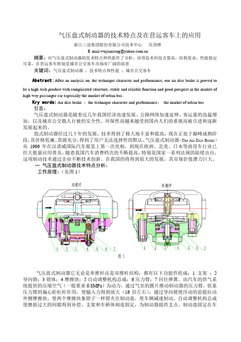
气压盘式制动器的技术特点及在营运客车上的应用浙江三浪集团股份有限公司技术中心吴剑增E-mail:wujianzeng@摘要:对气压盘式制动器的技术特点和性能作了分析,该项技术科技含量高,结构复杂、性能稳定可靠,在营运客车特别是城市公交客车市场有广阔的前景关键词:气压盘式制动器;技术特点和性能;城市公交客车Abstract:After an analysis on the technique character and performance, our air disc brake is proved tobe a high-tech product with complicated structure, stable and reliable function and good prospect in the market of high way passanger car especially the market of urban bus.Kry words: Air disc brake ;the technique character and performance;the market of urban bus引言:气压盘式制动器是随着近几年我国经济高速发展、公路网络加速延伸、客运量的迅猛增加,以及城市公交载人行驶的安全性、环保性而越来越受到国内人们的重视而被引进和逐渐发展起来的。
鼓式制动器经过几十年的发展,技术得到了极大地丰富和提高,现在正处于巅峰成熟阶段,其价格低廉、货源充分,得到了用户无法选择性的默认。
气压盘式制动器(The Air Disc Brake)从1996年在汉诺威国际汽车展览上第一次亮相,到现在欧洲、北美、日本等商用车行业已经大批量应用普及。
随着我国汽车消费档次的不断提高,特别是国家一系列法规的陆续出台,这项制动技术通过企业不断技术创新、在我国的将得到很大的发展,其市场价值潜力巨大。
盘式制动器在现代汽车上的应用与发展分析
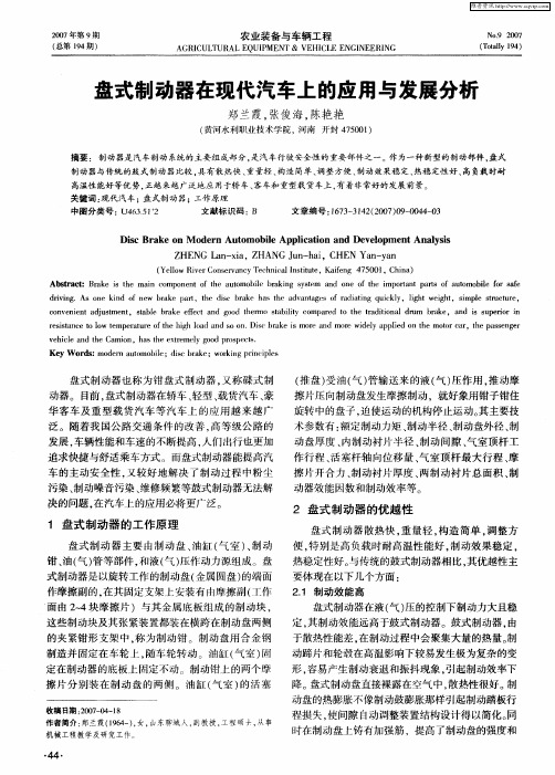
resistance to low temperature of the high load and SO on.Disc brake is more and more widely applied on the motor car,the passenger vehicle and the Camion,has the extremely good prospects. Key W ords:modern automobile;disc brake;working principles
盘式 制 动器 也称 为 钳 盘式 制 动 器 。又称 碟 式制 (推盘)受油 (气 )管输送来的液 (气 )压作用 ,推动摩
动器 。 目前 ,盘式 制动 器在轿 车 、轻 型 、载货汽 车 、豪 擦 片压 向制 动盘发 生摩擦 制 动 ,就 好象 用钳 子钳住
华 客 车 及 重 型 载 货 汽 车等 汽 车 上 的应 用 越 来 越 广 旋 转 中的盘子 ,迫使 运动 的机构 停止 运动 。其 主要 技
擦 片 分别 装 在制 动 盘 的两 侧 。油 缸 (气 室 )的 活 塞 降 。盘式 制 动盘直 接裸露 在空 气 中 ,散 热性 很好 。制
收稿 日期 :2007—04—18 作者简介 :郑兰霞(1964一),女,山东聊蛾 人,副教授 ,工程硕 士,从事 机械工程教 学及研 究工作。
(黄河水利职业技 术学 院,河南动 系统的主要组成部分 ,是汽车行驶安全性的重要部件之一 。作为一种新型的制动部件 ,盘式
盘式制动器在电机车上的应用
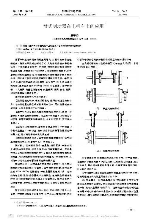
盘式制动器在电机车上的应用Ξ解翠英(大连昕迈机电控制工程公司,辽宁大连 116000)摘 要:阐述了盘式制动器在电机车上的应用及它的结构特点和连接形式。
关键词:电机车;盘式制动器;制动盘;制动力中图分类号:U463151 文献标识码:A 文章编号:1007-4414(2004)02-0035-02 随着车辆速度的提高和载重的增大,对制动的要求也越来越高。
传统的单纯闸瓦制动方式,大部分的热能由车轮来承担,1个车轮最多能安装1对闸瓦,而车轮的材质和结构不能自由选择,这就限制了它的使用。
而在盘式制动器中,作为磨擦副的制动盘的结构,可根据制动的要求进行多种方案的选择。
因此盘式制动器在铁道车辆上得到迅速发展。
早在20世纪30年代的德国柏林地铁车辆,首先用了BSI公司的盘式制动器,随后在高速列车(时速175km/h)也装用了这种制动器。
不久美国、荷兰也相继使用,现在美国、法国、日本、英国、和俄罗斯等国也普遍采用。
盘式制动器具有以下几种特点:①散热性能比较好,摩擦系数稳定,能得到较恒定的制动力。
它的热容量允许它采用较高的制动率,可以获得较高的减速度,从而也就缩短了制动距离。
②由于它可以自由地选择制动盘和合成闸片,使这一对磨擦副具有最佳的制动参数。
而且每个制动盘可以安装几个制动器,容易获得较高的摩擦系数,并且比较稳定,受速度的影响小。
③它还可以根据需要,在每根车轴上安装2个制动盘、3个制动盘甚至4个制动盘,使制动功率达到粘着条件所允许的最大值,这对高速车辆来说尤其重要。
④盘形制动运用经济。
由于制动盘摩擦面积大,承受的单位面积压力小,它磨耗率也小,寿命较长。
简而言之,它具有体积小、重量轻、结构紧凑、摩擦面积大、散热性能比较好、制动力恒定、制动率高等特点。
它的最大优点是可以根据制动力的大小自由地选择制动盘和制动器的数量,可以满足制动力要求比较大的情况下制动的需求,从而使制动功率达到粘着条件所允许的最大值。
在制动过程中,制动盘是受热载荷的主要部件,所以对制动盘的材质选择也就十分重要。
中英文文献翻译-盘式制动器的应用
附录A 外文文献原文China's engineers and users also stay in QianPan HouGu on the idea, and, before and after the application of the disc brake is commercial vehicle braking performance increase the optimal scheme. Because HouGu type brake on the temperature, the braking performance is very big, lead to the front axle attenuation disc brakes to bear on the part of the load, cause too much of the disc brake, brake piece of life of overload shorter. For cars in the braking process, because the role of the front, inertial load always takes all the car load 70% 80%, so the front wheel brake force to than the rear wheels. Manufacturers to cut costs, use the front disc brake, rear wheel drum brake mix of matching method. The QianPan HouGu type mixed brake, this is mainly due to the cost considerations. With the rapid development of China's national economy, the average consumer safety and environmental requirements of cars is increasing day by day, the miniature car industry from tiny truck started, the transition to tiny coaches, and then promoted to use tiny cars as transport, become the necessity of historical development; On the other hand, all miniature car companies already will capital and power steering mini car industry, to adapt to the different needs of consumers out mini car products, some private enterprises will also mini car into the breach of the car market as, constantly of price war, make mini car prices have no longer "too high", and began to close to ordinary people.Disc brake caliper disc and main overall type two kinds, modern car on the application of the most caliper disc brake, it is the rotation of the element is brake disc, fixed element is brake caliper. And, according to the brake caliper movement way and can be divided into set caliper disc brake, sliding caliper disc brake caliper disc brake and, including sliding caliper disc brake application more widely. The working principle of caliper disc brake is similar to a bicycle brake, braking process, the brake caliper will brake piece of extrusion to brake disc, along with the brake disc and lining block of the friction between the gradually will fall speed. And sliding caliper disc brake is brake caliper can be relatively brake disc axial sliding; Only in the inside of the brake disc set oil cylinders, and the outside of the brake block is in the grips attached on the body. Disc brakes in use process, also can appear fault, among them the more common wind resistance, underpowered and brake system has noise etc.Disc brake parts of fever in a narrow focus on the brake lining block, the unit and pressure than drum brakes, brake lining large block and clamp body of the piston direct contact with, so the quantity of heat of braking extremely easily to the brake fluid. So, make disc brakes easy to produce gas resistance phenomenon. But, if take corresponding measures, also can prevent air resistance happens.Miniature and affordable in our country are big car market, in recent years the domestic demand expansion drive the car market demand for miniature of the increase. Authorities say China's economy has entered into the platform, the moderate growth will pull the stable growth of car market. Last year, Chinese each enterprise benefits to improve, per capita disposable income increase, cause individual needs to improve the car; Countries carrying out the strategy for western development, to WeiChe market is tremendous potential demand of no doubt. From 0.9 to 1.6 L L, the price is suitable for China's national conditions, suitable for the current status of the development of the China is. Automobile brake clamps body stent is one of important parts, along with the car now design processing development of manufacturing technology, the brake clamps body in support of materials and processing method and so on is also in constant development, identify processing technology and clamping plan and design, attain thus to the automobile brake clamps body stents processing technology further deeper understanding;The main use of the software has Pro/e, ANSYS and CAPP. Pro/E software using 3 d entity the exact modeling, intuitive parts to reproduce the parts, accurate experience design intention, for parts of the process arrangement after help. Pro/E Mechanica module and the software ANSYS software, finite element analysis, combining do analysis processing produces in the process of the maximum displacement and the maximum stress, and the cutting tool for cutting dosages of the size of the choice to provide reliable basis. This topic use CAPP software developed including making the process route and process design, the complete process documents and improve the process of standardization and standardization. Early detection and solve. According to the retrieval, this in processing industries, and no one made the corresponding introduction. Pro/E software can be accurately to establish various large and complex models. ANSYS software in products manufacturing advance found potential problems, but its modeling ability are weak. The two tools combined, foster strengths and circumvent weaknesses, give full play to the advantages of two kinds of software research and development, is the first choice of complex mechanical structurescheme. This is also I choose the two software reasons. Previous engineering personnel with Pro/E complete three dimensions solid parts design, then use to Mechanica parts structure finite element analysis to find the place, and weak structure is improved. And I'm Pro/E, ANSYS will be applied to the design process of parts, make the past only in process actual implementation, can come into the open process defect, process design stage in can and The error after reflects the workpiece machining allowance method to calculate is, by definition, the processing, surface: its smallest machining allowance (Zbmin) are processing parts of two adjacent step freeways will limit of the difference of the minimum size; Its the biggest machining allowance (Zbmax) are processing parts of two adjacent step freeways will limit of the difference of the largest size. Inside surface processing, the minimum machining allowance is processed spares the maximum limit adjacent freeways will step size poor; Its the biggest machining allowance is processing components work of two adjacent step of the difference of the minimum size limit.The assistant time and basic time coincidence method, using the workbench processing center, get the staff in the cutting process completed work, and then, for auxiliary of the area is larger, and the volume of parts and relatively small, so can use one processing DuoGe parts to make the parts, the piece processing time as little as the basis, double the nc machining center area can also arranged four parts. The rotary worktable, two workpiece in processing at the same time, the clamping workpiece, the other two rotating, processing of just install two workpiece.Selection of cutting parameter and the formulation of &fair standards. Choose the right to improve the cutting dosages, cutting efficiency and guarantee the necessary tools durability and economy, ensure machining quality, has the vital role. Reasonable choice when processing cutting dosages should first choose a as far as possible big, secondly, optimizing the back of choice a larger feeding, and the last in the cutting tool durability, process system stiffness, machine tool power under the terms of the license, the rational choice of cutting speed. &fair standards also says time is fixed in a certain technology organization established under the condition of complete unit out products (such as a parts) or a job (such as a process that must be consumed time). &fair standards is not only, also be the measure index productivity arrange production plan, the calculations of the productioncost is an important basis for new or expansion of the factory, is also (or workshop) computing devices and workers number of basis.Brake caliper disc brake the car body is the critical, brake movement is in the grips body on the final. Installed in clamp body on parts and 16 pieces. One of the more important parts: brake caliper piston, piston callipers at the stents, sealing ring, friction piece, brake caliper shaft pins, spring of and purge screw, etc. Studio, brake fluid through the clamp body JinYou mouth will be pressure to brake caliper Detroit, and by the brake friction pressure before the pistons will to block, press the brake disc, and make clamp body in the brake caliper shaft pins, driving the sliding friction, also after pressure brake disc brake, complete action. The car brake disc brake caliper body shape, structure, material complex special for QT450-10, hardness is HB143-217, machining allowance for 3 mm, form and position tolerances stricter requirements. This product is the important parts, and related to China's automobile brake disc importied problem. In the existing gm in machine tool is completed or processing difficult brake caliper body, especially the lumen of processing, tank must determine the process, to ensure the quality of the processing equipment. Because in general on the machine processing, so blank datum positioning to repeated use, the request to have the precise location of the datum plane, this and use machining center is a very big difference. Such as we are in the process of slot PNE480 CNC machine even with pure inside the car, to ensure that slot cavity type, detection is precision with anatomical projection and after adjustment method of projection.Were now being mass production craft ready to work, according to the auto industry "high starting point, large quantities of specialization," the policy, we have identified on the domestic equipment, save funds, and choose the XK6040 CNC milling machine.附录B 外文文献翻译中国的工程师和用户还停留在前盘后鼓的理念上,而前、后盘式制动器的应用才是商用车提高制动性能的最佳方案。
毕业设计译文(盘式制动器)

A disc brake test stand for measurement of airborne wear particlesABSTRACTDuring braking, there is wear on both the rotor and the pads. This process generates particles that may become airborne. In fi eld tests, it is diffi cult to distinguish these particles from others in the surrounding environment.Therefore, a laboratory test stand has been designed which allows control of the cleanliness of the surrounding air. The test stand consists of a front right brake assembly mounted in a sealed chamber. A braking load is applied by a pneumatic system and the rotor, which has been pre-conditioned with a rust layer to simulate a car standing parked overnight in a wet environment, is driven by an electric motor. The number and size of airborne wear particles are then measured. This experimental set-up has been verifi ed by an initial test series performed at low braking loads. The results suggest that this test stand can be used to study rust layer removal from the rotor.key words: wear; airborne particles; disc brake; test stand; rust layerINTRODUCTIONMany studies have shown an association between adverse health effects and the concentration of airborne particles in the atmosphere.1–3 In urban environments, airborne particles can come from different sources, e.g. demolition and construction,4 resuspended road dust,5 wheel-to-rail contact,6,7 car-to-road contact8,9 and disc brakes.10,11 During braking, both the brake pads and rotors are worn, generating wear particles. Some of these particles are deposited on the brake hardware, and others become airborne. Furthermore, to ensure robust brake performance, some brake systems may require the pads to frequently be in low pressure contact with the rotor. This dragging may remove any rust layer, which may build standing parked overnight in a wet environment, from the rotor and keep the contact surfaces clean. However, the resulting drag torque increases the fuel consumption and generates wear particles, because the pads are still in contact with the rotor after the rust layer has been removed. It is therefore desirable to reduce the dragging without affecting the performance of the brakes.When measuring airborne brake particles in fi eld tests, it can be diffi cult to distinguish them from other traffic-generated aerosols. Therefore, it may be preferable to use laboratory tests that allow control of the cleanliness of the surrounding air. Although several test stands have been built to study wear and friction at the pad-to-rotor interface, few studies12,13 have focused on wear particles. In a laboratory test stand, the cleanliness of the surrounding air can be controlled, enabling more accurate study of airborne brake wear particles. With this in mind, a laboratory component test stand has been designed to measure the number and size of airborne wear particles generated by disc brakes. The purpose of this paper was to describe this test stand and present the results of a fi rst test series to verify the experimental set-up. These tests focus on rust layer removal at low braking loads.EXPERIMENTAL SET-UPIn this test stand, a front right brake assembly from a passenger car is used. The front right brake assembly consists of a knuckle, the wheel bearing and the disc brake assembly. The disc brake assembly in turn consists of a ventilated rotor, a sliding caliper with a single piston and two brake pads (Figure 1). The fi nger side brake pad includes a K-typethermocouple that measures the temperature near the fi nger side pad-to-rotor contact.A schematic diagram of the test stand is given in Figure 2. An electric direct current motor (K) with a nominal torque of 191 Nm drives the rotor, and a pneumatic system (M) connected to the front right brake assembly (H) is used to apply a controlled braking load. When the brake is applied, the motor continues to drive the system at a stationary rotational speed, i.e. the test system throttles and brakes at the same time. A drive shaft (L) transfers the torque from the motor to the wheel bearing, which in turn rotates the disc. The motor and the drive shaft are connected by a fi xed coupling, and the wheel bearing and the drive shaft are connected by a splined coupling. The knuckle is mounted to a suspension device. A sealing chamber (G) seals the front right brake assembly from the surroundings. The electric motor is balanced with bearings on each end. The applied torque on the motor is measured using a calibrated strain gauge force sensor multiplied by the distance from the motor centre,with an accuracy of ±2.2%. The rotational speed of the disc is measured by a built-in Hall effect sensor in the wheel bearing, with 48 pulses per revolution. A pneumatic system generates controlled low pressure levels of up to 4 bar in the brakecylinder. The pressure level is measured with an accuracyof ±0.5% by a calibrated piezoelectric pressure sensor near the inlet of the brake cylinder.盘式制动器试验台上测量空气中磨损颗粒摘要在制动过程中,制动盘和摩擦片都有磨损。
关于盘式制动器的参考文献

关于盘式制动器的参考文献
以下是关于盘式制动器的一些参考文献,供你参考:
1. "Automotive Brake Systems" by James D. Halderman 这
本书是关于汽车制动系统的综合指南,其中包括盘式制动器的原理、设计和性能分析等内容。
2. "Brake Design and Safety" by Rudolf Limpert 这本书详细介绍了制动系统的设计和安全性能,包括盘式制动器的设计原理、材料选择和制动力分析等方面。
3. "Brake Handbook" by Fred Puhn 这本手册提供了关于制动系统的全面介绍,包括盘式制动器的原理、设计、维护和故障排除
等方面的内容。
4. "Vehicle Brake Systems: A Textbook for Technicians" by Tom Denton 这本教材专门为汽车技术人员编写,涵盖了制动系
统的各个方面,包括盘式制动器的工作原理、构造和维护等内容。
5. "Brake Technology Handbook" by Bert Breuer and
Karlheinz H. Bill 这本手册提供了关于制动技术的详细信息,包括盘式制动器的设计、材料和制动系统的性能评估等方面的内容。
这些参考文献涵盖了盘式制动器的原理、设计、性能和维护等方面的知识,可以帮助你更全面地了解盘式制动器的工作原理和应用。
请根据你的具体需求选择适合的文献进行深入研究。
《文献翻译-盘式制动器》
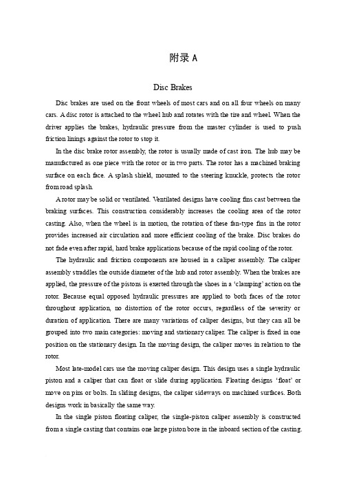
附录ADisc BrakesDisc brakes are used on the front wheels of most cars and on all four wheels on many cars. A disc rotor is attached to the wheel hub and rotates with the tire and wheel. When the driver applies the brakes, hydraulic pressure from the master cylinder is used to push friction linings against the rotor to stop it.In the disc brake rotor assembly, the rotor is usually made of cast iron. The hub may be manufactured as one piece with the rotor or in two parts. The rotor has a machined braking surface on each face. A splash shield, mounted to the steering knuckle, protects the rotor from road splash.A rotor may be solid or ventilated. V entilated designs have cooling fins cast between the braking surfaces. This construction considerably increases the cooling area of the rotor casting. Also, when the wheel is in motion, the rotation of these fan-type fins in the rotor provides increased air circulation and more efficient cooling of the brake. Disc brakes do not fade even after rapid, hard brake applications because of the rapid cooling of the rotor.The hydraulic and friction components are housed in a caliper assembly. The caliper assembly straddles the outside diameter of the hub and rotor assembly. When the brakes are applied, the pressure of the pistons is exerted through the shoes in a ‘clamping’ action on the rotor. Because equal opposed hydraulic pressures are applied to both faces of the rotor throughout application, no distortion of the rotor occurs, regardless of the severity or duration of application. There are many variations of caliper designs, but they can all be grouped into two main categories: moving and stationary caliper. The caliper is fixed in one position on the stationary design. In the moving design, the caliper moves in relation to the rotor.Most late-model cars use the moving caliper design. This design uses a single hydraulic piston and a caliper that can float or slide during application. Floating designs ‘float’or move on pins or bolts. In sliding designs, the caliper sideways on machined surfaces. Both designs work in basically the same way.In the single piston floating caliper, the single-piston caliper assembly is constructed from a single casting that contains one large piston bore in the inboard section of the casting.Inboard refers to the side of the casting nearest the center line of the car when the caliper is mounted. A fluid inlet hole and bleeder valve hole are machined into the inboard section of the caliper and connect directly to the piston bore.The caliper cylinder bore contains a piston and seal. The seal has a rectangular cross section. It is located in a groove that is machined in the cylinder bore. The seal fits around the outside diameter of the piston and provides a hydraulic seal between the piston a nd the cylinder wall. The rectangular seal provides automatic adjustment of clearance between the rotor and shoe and linings following each application. When the brakes are applied, the caliper seal is deflected by the hydraulic pressure and its inside diameter rides with the piston within the limits of its retention in the cylinder groove. When hydraulic pressure is released, the seal relaxes and returns to its original rectangular shape, retracting the piston into the cylinder enough to provide proper running clearance. As brake linings wear, piston travel tends to exceed the limit of deflection of the seal; the piston therefore slides in the seal to the precise extent necessary to compensate for lining wear.The top of the piston bore is machined to accept a sealing dust boot. The piston in many calipers is steel, precision ground, and nickel chrome plated, giving it a very hard and durable surface. Some manufacturers are using a plastic piston. This is much lighter than steel and provides for a much lighter brake system. The plastic piston insulates well and prevents heat from transferring to the brake fluid. Each caliper contains two shoe and lining assemblies. They are constructed of a stamped metal shoe with the lining riveted or bonded to the shoe and are mounted in the caliper on either side of the rotor. One shoe and lining assembly is called the inboard lining because it fits nearest to the center line of the car. The other is called the outboard shoe and lining assembly.As already mentioned, the caliper is free to float on its two mounting pins or bolts. Teflon sleeves in the caliper allow it to move easily on the pins. During application of the brakes, the fluid pressure behind the piston increases. Pressure is exerted equally against the bottom of the piston and the bottom of the cylinder bore. The pressure applied to the piston is transmitted to the inboard shoe and lining, forcing the lining against the inboard rotor surface. The pressure applied to the bottom of the cylinder bore forces the caliper to move on the mounting bolts toward the inboard side, or toward the air. Because the caliper is one piece, this movement causes the outboard section of the caliper to apply pressure against the back of the outboard shoe and lining assembly, forcing the lining against the outboard rotorsurface. As the line pressure builds up, the shoe and lining assemblies are pressed against the rotor surfaces with increased force, bringing the car to a stop.The application and release of the brake pressure actually causes a very slight movement of the piston and caliper. Upon release of the braking effort, the piston and caliper merely relax into a released position. In the released position, the shoes do not retract very far from the rotor surfaces.附录B外文翻译:盘式制动器许多汽车所有四个车轮,盘式制动器是用在大多数轿车的前轮上。
盘式制动器外文文献

机械工程学院毕业设计(外文翻译)附件外国文献HYDRAULIC BRAKE BASICSAir brakes get more attention, but hydraulic brakes are installed on more vehicles. Understanding how they work is the first step to safe, cost-effective diagnosis and repair.Ever wonder why there can't be just one kind of brake? It's because airand h ydraulic brakes each have operating characteristics that make one or the other ideal for certain applications.In heavy-duty combination vehicles, air is the clear choice because of the large volume of liquid that would be needed to CATIA all the wheel cylinders. Plus, dealing with glad hand and hoses filled with hydraulic fluid would be messy.But for light and medium-duty straight-truck applications, hydraulic brakes offer advantages including:•Brake feel — that is, as the pedal is pressed farther down, effort increases;•High line pressures, which permit the use of lighter, more compact braking components;•Less initial expense, due to smaller and fewer components;•Cleanliness — hydraulic brakes are closed systems;•Ease of locating leaks, since fluid is visible.There are many more permutations of hydraulic brake systems than found in air systems, but all have basic similarities.THE HYDRAULIC SYSTEMAll hydraulic brake systems contain a fluid reservoir, a master cylinder, whichproduces hydraulic pressure, hydraulic lines and hoses to carry pressurized fluid to the brakes, and one or more wheel cylinder(s) on each wheel.The wheel cylinders expand under fluid pressure, and force the brake shoes against the insides of the drums. If disc brakes are used, calipers, with integral cylinders, clamp down on the rotors when pressure is applied.Because a vehicle must be able to stop much more quickly than it can accelerate, a tremendous amount of braking force is needed. Therefore, the retarding horsepower generated by the brakes must be several times that of the engine.In order to develop the forces required to hold the brake linings against the drums or discs, and to achieve controlled deceleration, it is necessary to multiply the original force applied atthe brake pedal.When a hydraulic system is used, the only mechanical leverage is in the foot pedal linkage. However, varying the diameter of the wheel cylinders or caliper diameters, in relation to the master cylinder bore diameter, provides an additional increase in ratio.In a hydraulic system, the pressure delivered by the various wheel cylinders is directly affected by the areas of their pistons. For example, if one wheel-cylinder piston has an area of 2 square inches, and another piston has an area of 1 square inch, and the system pressure is 400 psi,the 2-square-inch piston will push against the brake shoes with a force of 800 pounds. The1-square-inch piston will exert a force of 400 pounds. The ratio between the areas of the master cylinder and the wheel cylinders determine the multiplication of force at the wheel cylinder pistons.Keep in mind that the larger a wheel cylinder's diameter, the more fluid must be supplied by the master cylinder to fill it. This translates into a longer master-cylinder stroke.If the master cylinder bore diameter is increased and the applying force remains the same, less pressure will be developed in the system, but a larger wheel-cylinder piston can be used to achieve the desired pressure at the wheel cylinder. Obviously, a replacement master cylinder, wheel cylinder or caliper must be of the same design and bore as the original unit.Hydraulic brake systems are split systems, comprising two discreet braking circuits. One master-cylinder piston and reservoir is used to actuate the brakes on one axle, with a separate piston and reservoir actuating the brakes on the other axle(s). Although rare, some light-duty brake systems are split diagonally rather than axle by axle.The reason for the split system is that if a leak develops in one hydraulic circuit, the other will stop the vehicle. Of course, the vehicle shouldn't be driven any farther than necessary to havethe brake system repaired.When one of the hydraulic circuits fails, a pressure -differential switch senses unequal pressure between the two circuits. The switch contains a piston located by a centering spring and electrical contacts at each end. Fluid pressure from one hydraulic circuit is supplied to one end of the pressure-differential switch, and pressure from the other circuit is supplied to the other end. As pressure falls in one circuit, the other circuit's normal pressure forces the piston to the inoperative side, closing the contacts and illuminating a dashboard warning light.POWER ASSISTPower assist units, or boosters, reduce operator effort at the brake pedal. Vacuum boosters, popular on light-duty vehicles, make use of an engine vacuum on one side of a diaphragm, and atmospheric pressure on the other side. A valve allows the vacuum to act on the diaphragm in proportion to brake pedal travel. This assists the pedal effort, and allows increased pressure onthe brake fluid, without an undue increase in pedal effort.Other types of boosters use hydraulic pressure — either from the vehicle's power steering pump or from a separate electric pump, or both — to assist pedal effort. As the brake pedal is depressed, a valve increases hydraulic pressure in a boost chamber to apply increased pressure to the master cylinder pistons.Some systems use both vacuum and hydraulic assist. In other systems, air pressure from an onboard compressor is used to generate hydraulic system pressure.VALVINGValves commonly found in hydraulic brake systems include: Proportioning, orpressure-balance valves. These restrict a percentage of hydraulic pressure to the rear brakes when system pressure reaches a preset high value. This improves front/rear brake balance duringhigh-speed braking, when some of a vehicle's rear weight is transferred forward, and helps prevent rear-wheel lockup. Some proportioning valves are height-sensing. That is, they adjustrear-brake pressure in response to vehicle load. As a vehicle's load increases (decreasing height) more hydraulic pressure to the rear brake s is allowed;Metering valves. These hold off pressure to front disc brakes to allow rear drum brake shoes to overcome return-spring pressure and make contact with the rear drums. This prevents locking the front brakes on slippery surfaces under light braking applications. These valves do not come into play during hard braking.PARKINGThe parking function varies greatly among hydraulic brake systems. Many light-duty vehicles with rear drum brakes use a passenger-car type lever-and-cable setup. A ratcheted lever or foot pedal pulls a cable, which, in turn, pulls a lever assembly at each rear wheel end. The lever forces the brake shoes apart, and they are mechanically held against the drums until the ratchet is released.Other parking systems include spring chambers, like those used onair-brake systems. These are spring-engaged, but are disengaged by hydraulic pressure instead of air.ANTILOCKOn many hydraulically braked light-duty trucks, brakes are used on the rear wheels to preserve braking stability when these vehicles are lightly loaded. Front and rear-wheel is usually an option, except for vehicles over 10,000 pounds GVWR, which are required to have steer and drive-axleIn current hydraulic systems, a dump valve releases pressurized hydraulic fluid into an accumulator in the event of an impending wheel lockup.An electronic control box receives speed signal(s) from sensors in the transmission and/or at the wheels. When the brakes are applied, the control box senses the decrease in rear wheel speed, and activates the dump valve(s) if the rate of deceleration exceeds a predetermined limit.The control box energizes the dump valve with a series of rapid pulses to bleed-offwheel hydraulic pressure. Continuing in mode, the dump valve is pulsed to keep the wheels rotating, while maintaining controlled deceleration.At the end of such a stop, the valve and any fluid in the accumulator is returned to the master cylinder. Normal brake operation resumes.FOUNDATION BRAKESFoundation brakes in hydraulic systems can be either drum or disc. In many applications, discs are used on the front axle and drums on the rear.Drum brakes are said to be self-energizing. That's because when the brake shoes expand and contact a rotating drum, the leading, or forward, brake shoe is pushed against the trailing shoe by the force of the moving drum. This results in higher lining-to-drum pressure than would be produced by the wheel cylinder alone.As brake linings wear, the shoes periodically must be moved closer to the drums to ensure proper contact during braking. While some older drum brake assemblies are manually adjusted, most are automatic. These use a star wheel or ratchet assembly, which senses when the wheel cylinder has traveled beyond its normal stroke, and expands the pivot point at the other end ofthe brake shoes.In addition to being one of the friction elements, the brake drum or rotor also acts as a heat sink. It must rapidly absorb heat during braking, and hold it until it can be dissipated into the air. The heavier a drum or rotor is, the more heat it can hold.This is important, since the hotter the brake linings get, the more susceptible they are to heat fade. Heat fade is induced by repeated hard stops and results in reduced lining-to-drum/rotor friction and increased vehicle stopping distance. As a rule, high-quality linings will display less heat fade than inferior ones. Also, are far more resistant to heat fade than drum brakes.Another type of fade that brakes are susceptible to is water fade. Drum brakes, with their large surface areas, apply fewer pounds per square inch of force between lining and drum during a stop than disc brakes. This, added to the drum's water-retaining shape, promotes hydroplaning between shoe and drum under wet conditions. The result is greatly increased stopping distance.Disc brakes, with their smaller friction surfaces and high clamping forces, do a good job of wiping water from rotors, and display little reduction in stopping capability when wet.中文翻译液压制动基础空气制动系统得到更多的关注,但更多的车辆上安装液压制动器。
基于ug的盘式制动器设计外文文献
一个复杂的特征值分析与设计相结合的实验方法(DOE)研究了盘式制动器制动尖叫摘要:本文提出了一种研究结合制动盘的盘式制动器的制动尖叫的影响因素探讨利用统计回归技术的有限元模拟。
复杂的特征值分析(CEA)已经广泛应用于不稳定制动系统的预测模型。
这个有限元模型是与试验模态测试结果相互关联的。
使用盘式制动器的各种几何配置是基于制动尖叫和制动盘的几何形状之间的输入输出关系建立的预测。
影响的各种因素:即背板的杨氏模量;背板厚度;槽间的距离,槽的宽度和角度;使用实验(DOE)技术方法。
预测数学模型的基本上已大部分实验证明了其影响因素的充分性和验证了仿真。
预测结果表明,制动尖叫倾向性可以通过增加杨氏模量的背板与摩擦材料两侧加上倒角和引入槽结构改性摩擦材料的形状来减少制动尖叫。
模拟制动尖叫使用CEA和DOE发现通过验证试验统计相结合的方法是足够的。
这种结合的方法将在盘式制动器的设计阶段是有用的。
关键词:盘式制动器的制动尖叫;有限元分析;试验模态分析;实验设计一.引言制动尖叫噪声问题是由摩擦力不稳定性引起的动态振动(凯,2002)。
制动操作过程中,焊盘与盘之间的摩擦可导致系统中的动态不稳定性。
通常制动尖叫发生在1和20千赫之间的频率范围。
尖叫声是一个复杂的现象,部分原因是由于其强烈依赖于许多参数,部分因为制动系统中机械的相互作用。
因为在摩擦界面接触非线性的影响使得机械的相互作用是非常复杂。
尖叫声是间歇的或随机的。
在一定的条件下,即使当车辆是全新的,它往往会产生尖叫噪声,已消除噪声的目的进行了更广泛的研究。
然而,尖叫噪音的机械细节尚未完全理解(乔等人,2008)。
一些理论已经被制定,解释制动尖叫的机制,无数的研究已经取得了不同程度的成功将其应用到盘式制动器的动力学(金凯德等人,2003)。
这个不稳定的爆发的原因已被归因于不同的原因。
一些主要的原因是摩擦的特性与接触点的速度变化;磁盘的相对取向的变化和摩擦片导致的变形的摩擦力和颤振失稳即发现有一个恒定的摩擦系数。
盘式制动器摘要

摘要汽车制动系统是汽车最重要的主动安全系统,制动器则是制动系统的执行机构,其性能好坏直接影响汽车的安全。
盘式制动器作为鼓式制动器的替代产品,具有热稳定性好、反应灵敏等优势,但是盘式制动器本身也存在一些问题,并且鼓式制动器存在的一些问题,虽然盘式制动器有一定程度改善,但并未得到完全解决,如热衰退、制动噪声等。
本文开篇阐明了盘式制动器发展与现状,然后是设计的背景,性质及任务。
通过对轿车盘式制动器的深入学习和设计实践,主要是对轿车盘式制动器的零部件结构选型及设计计算,更好地学习并掌握盘式制动器的结构原理与设计计算的相关知识和方法。
介绍了盘式制动器的各种类型,性能等,分析了盘式制动器和摩擦衬片的特性。
关键词:盘式制动器; 设计;性能分析AbstractAutomobile brake system is the most important initiative safety system, brake is the enforcer of brake system, whose performance affects the vehicle’s safety directly. As the substitution of drum brake, disc brake has advantages of fine thermal stability, delicate feedback, and so on. But it also has some defects, and though the problems of drum brake have been improved, they are not resolved completely, such as thermal fade and brake noise.This paper illustrated disc brake’s development at beginning, then the design’s background, quality and mission. Through the disc brake in-depth study and design practice, mainly for car’s disc brake structure selection and design ca lculation, can better study and master the disc brake structure and working principle and the related knowledge and methods. Introduce the brake disc’s kind and performance. Analyze the disc brake and rub linings’ behavior.Key words: disc brake; design; Performance Analysis目录摘要 iAbstract ii目录 iii第一章绪论1.1 设计的背景及意义1.2 盘式制动器的发展现状1.3 设计的性质和任务1.4论文内容概述第二章盘式制动器的概述2.1 制动器性能简介2.2 盘式制动器的类型2.2.1 浮动盘式制动器2.2.2 固定钳盘式制动器2.3 盘式制动器的优点第三章盘式制动器设计3.1制动系统的设计要求3.2 盘式制动器主要参数的确定 1 3.3盘式制动器的设计计算3.4衬片磨损特性的计算3.5制动器主要零件的结构设计第四章总结参考文献致谢。
气压盘式制动器在大客车上的应用

气压盘式制动器在大客车上的应用2009-9-14 20:25:00 来源:中国自动化网浏览:523 网友评论条点击查看摘要:与传统的鼓式制动器相比。
气压盘式制动器无论在性能还是可靠性方面都表现出极大的优势。
通过简要介绍气压盘式制动器的结构、特点及应用状况,提出了一种气压盘式制动器制动力矩的计算方法,并对气压盘式制动器在应用设计中应注意的一些问题作了初步的探讨。
关键词:气压盘式制动器;应用设计;匹配The application of air disc brake in busPENG De-yang(CV R&D Center of DFL,Shiyan 442001,China)Abstract: Compared with the traditional brake,the air diskbrake has great ad vantage in both performance an ddependability.This paper simply induced the s tructurecharacteristic an d status of air disc brake,brought up a methodfor d esigning an d calculating of brake moment of the air discbrake,and made a pri mary discussion about some issues towhich should be paid attention in the proc ess of applicationdesign.Key words:air disc brake;application design ;matching近年来,随着汽车消费的不断升级,以及国内厂家在相关领域技术的不断进步和产品价格的降低,气压盘式制动器在高档客车产品上得到了越来越广泛的应用。
- 1、下载文档前请自行甄别文档内容的完整性,平台不提供额外的编辑、内容补充、找答案等附加服务。
- 2、"仅部分预览"的文档,不可在线预览部分如存在完整性等问题,可反馈申请退款(可完整预览的文档不适用该条件!)。
- 3、如文档侵犯您的权益,请联系客服反馈,我们会尽快为您处理(人工客服工作时间:9:00-18:30)。
附录A 外文文献原文China's engineers and users also stay in QianPan HouGu on the idea, and, before and after the application of the disc brake is commercial vehicle braking performance increase the optimal scheme. Because HouGu type brake on the temperature, the braking performance is very big, lead to the front axle attenuation disc brakes to bear on the part of the load, cause too much of the disc brake, brake piece of life of overload shorter. For cars in the braking process, because the role of the front, inertial load always takes all the car load 70% 80%, so the front wheel brake force to than the rear wheels. Manufacturers to cut costs, use the front disc brake, rear wheel drum brake mix of matching method. The QianPan HouGu type mixed brake, this is mainly due to the cost considerations. With the rapid development of China's national economy, the average consumer safety and environmental requirements of cars is increasing day by day, the miniature car industry from tiny truck started, the transition to tiny coaches, and then promoted to use tiny cars as transport, become the necessity of historical development; On the other hand, all miniature car companies already will capital and power steering mini car industry, to adapt to the different needs of consumers out mini car products, some private enterprises will also mini car into the breach of the car market as, constantly of price war, make mini car prices have no longer "too high", and began to close to ordinary people.Disc brake caliper disc and main overall type two kinds, modern car on the application of the most caliper disc brake, it is the rotation of the element is brake disc, fixed element is brake caliper. And, according to the brake caliper movement way and can be divided into set caliper disc brake, sliding caliper disc brake caliper disc brake and, including sliding caliper disc brake application more widely. The working principle of caliper disc brake is similar to a bicycle brake, braking process, the brake caliper will brake piece of extrusion to brake disc, along with the brake disc and lining block of the friction between the gradually will fall speed. And sliding caliper disc brake is brake caliper can be relatively brake disc axial sliding; Only in the inside of the brake disc set oil cylinders, and the outside of the brake block is in the grips attached on the body. Disc brakes in use process, also can appear fault, among them the more common wind resistance, underpowered and brake system has noise etc.Disc brake parts of fever in a narrow focus on the brake lining block, the unit and pressure than drum brakes, brake lining large block and clamp body of the piston direct contact with, so the quantity of heat of braking extremely easily to the brake fluid. So, make disc brakes easy to produce gas resistance phenomenon. But, if take corresponding measures, also can prevent air resistance happens.Miniature and affordable in our country are big car market, in recent years the domestic demand expansion drive the car market demand for miniature of the increase. Authorities say China's economy has entered into the platform, the moderate growth will pull the stable growth of car market. Last year, Chinese each enterprise benefits to improve, per capita disposable income increase, cause individual needs to improve the car; Countries carrying out the strategy for western development, to WeiChe market is tremendous potential demand of no doubt. From 0.9 to 1.6 L L, the price is suitable for China's national conditions, suitable for the current status of the development of the China is. Automobile brake clamps body stent is one of important parts, along with the car now design processing development of manufacturing technology, the brake clamps body in support of materials and processing method and so on is also in constant development, identify processing technology and clamping plan and design, attain thus to the automobile brake clamps body stents processing technology further deeper understanding;The main use of the software has Pro/e, ANSYS and CAPP. Pro/E software using 3 d entity the exact modeling, intuitive parts to reproduce the parts, accurate experience design intention, for parts of the process arrangement after help. Pro/E Mechanica module and the software ANSYS software, finite element analysis, combining do analysis processing produces in the process of the maximum displacement and the maximum stress, and the cutting tool for cutting dosages of the size of the choice to provide reliable basis. This topic use CAPP software developed including making the process route and process design, the complete process documents and improve the process of standardization and standardization. Early detection and solve. According to the retrieval, this in processing industries, and no one made the corresponding introduction. Pro/E software can be accurately to establish various large and complex models. ANSYS software in products manufacturing advance found potential problems, but its modeling ability are weak. The two tools combined, foster strengths and circumvent weaknesses, give full play to the advantages of two kinds of software research and development, is the first choice of complex mechanical structurescheme. This is also I choose the two software reasons. Previous engineering personnel with Pro/E complete three dimensions solid parts design, then use to Mechanica parts structure finite element analysis to find the place, and weak structure is improved. And I'm Pro/E, ANSYS will be applied to the design process of parts, make the past only in process actual implementation, can come into the open process defect, process design stage in can and The error after reflects the workpiece machining allowance method to calculate is, by definition, the processing, surface: its smallest machining allowance (Zbmin) are processing parts of two adjacent step freeways will limit of the difference of the minimum size; Its the biggest machining allowance (Zbmax) are processing parts of two adjacent step freeways will limit of the difference of the largest size. Inside surface processing, the minimum machining allowance is processed spares the maximum limit adjacent freeways will step size poor; Its the biggest machining allowance is processing components work of two adjacent step of the difference of the minimum size limit.The assistant time and basic time coincidence method, using the workbench processing center, get the staff in the cutting process completed work, and then, for auxiliary of the area is larger, and the volume of parts and relatively small, so can use one processing DuoGe parts to make the parts, the piece processing time as little as the basis, double the nc machining center area can also arranged four parts. The rotary worktable, two workpiece in processing at the same time, the clamping workpiece, the other two rotating, processing of just install two workpiece.Selection of cutting parameter and the formulation of &fair standards. Choose the right to improve the cutting dosages, cutting efficiency and guarantee the necessary tools durability and economy, ensure machining quality, has the vital role. Reasonable choice when processing cutting dosages should first choose a as far as possible big, secondly, optimizing the back of choice a larger feeding, and the last in the cutting tool durability, process system stiffness, machine tool power under the terms of the license, the rational choice of cutting speed. &fair standards also says time is fixed in a certain technology organization established under the condition of complete unit out products (such as a parts) or a job (such as a process that must be consumed time). &fair standards is not only, also be the measure index productivity arrange production plan, the calculations of the productioncost is an important basis for new or expansion of the factory, is also (or workshop) computing devices and workers number of basis.Brake caliper disc brake the car body is the critical, brake movement is in the grips body on the final. Installed in clamp body on parts and 16 pieces. One of the more important parts: brake caliper piston, piston callipers at the stents, sealing ring, friction piece, brake caliper shaft pins, spring of and purge screw, etc. Studio, brake fluid through the clamp body JinYou mouth will be pressure to brake caliper Detroit, and by the brake friction pressure before the pistons will to block, press the brake disc, and make clamp body in the brake caliper shaft pins, driving the sliding friction, also after pressure brake disc brake, complete action. The car brake disc brake caliper body shape, structure, material complex special for QT450-10, hardness is HB143-217, machining allowance for 3 mm, form and position tolerances stricter requirements. This product is the important parts, and related to China's automobile brake disc importied problem. In the existing gm in machine tool is completed or processing difficult brake caliper body, especially the lumen of processing, tank must determine the process, to ensure the quality of the processing equipment. Because in general on the machine processing, so blank datum positioning to repeated use, the request to have the precise location of the datum plane, this and use machining center is a very big difference. Such as we are in the process of slot PNE480 CNC machine even with pure inside the car, to ensure that slot cavity type, detection is precision with anatomical projection and after adjustment method of projection.Were now being mass production craft ready to work, according to the auto industry "high starting point, large quantities of specialization," the policy, we have identified on the domestic equipment, save funds, and choose the XK6040 CNC milling machine.附录B 外文文献翻译中国的工程师和用户还停留在前盘后鼓的理念上,而前、后盘式制动器的应用才是商用车提高制动性能的最佳方案。