miniAHRS说明书
mini车载说明书

MINI-MDVRShenzhen Technology Co., Ltd.版权所有侵权必究All rights reserved目录1产品介绍 (3)1.1产品概述 (3)1.2产品的主要功能 (3)1.3性能参数 (3)2操作说明 (5)2.1前面板 (5)2.2后面板............................................................................................ 错误!未定义书签。
2.3遥控器 (5)3基本操作手册............................................................................................. 错误!未定义书签。
3.1系统的开启与登陆.......................................................................... 错误!未定义书签。
3.1.1系统开启 ........................................................................................ 错误!未定义书签。
3.1.2系统登陆 ........................................................................................ 错误!未定义书签。
3.2系统的查询与设置.......................................................................... 错误!未定义书签。
3.2.1设备操作 ........................................................................................ 错误!未定义书签。
西马吉克 ALPHA MINI 底座 用户手册说明书

Safety Switch Connector Peripheralconnector
06 ProductIntroduction
Dimensionsofthewheelbase(mm)
110*110*167.5smallbody size (mm),exquisite craftmanship
2.4g independentchannel,avoiding interference from Bluetoothand Wi-Fi.
New Alpha firmware features.
04 ProductIntroduction
*Entry-levelDirectDriveServoMotor,anexcellentstartingpointforyourSim-Racingjourney *Optimizedshaftdesign,10Nm maxtorque *AIdynamicalgorithm fortorquedistribution,greaterfidelity,noneedforalargertorque *Improvedexpansionsleeve,bettersynergy,bettersynchronization
Diverse peripheralsupport,enabling greater authenticity in simulation.
Safe Operation
08 Safety Instructions
*Itisstrictlyforbiddentoexposethedeviceanditspowersupplytorainorhumidityinordertoavoidshortcircuitandelectricshockthatmaycausedevice malfunctionandfire.
Pellicon Mini和MiniX 保持器用户指南说明书

Pellicon® Mini and MiniX HoldersUser GuideThe life science business of MerckKGaA, Darmstadt, Germany operates asMilliporeSigma in the U.S. and Canada.2 Pellicon® Mini and MiniX Holders User Guide 3 ContentsIntroduction (5)Unpacking (6)Plumbing and Instrumentation (8)Assembling the Holders (9)Feed and Retentate Fitting Connections (9)Permeate Fitting Connections (9)Connecting Pressure Gauge AdapterFittings to FEED and RETENTATE Fittings (10)Connecting the Pressure Gauge (12)Connect the Permeate Fittings (13)Inserting the Pellicon® Cassettes (13)Attaching the End Plate (15)Autoclave Setup (17)Ordering Information (18)Spare Parts and Accessories (18)4 Pellicon® Mini and MiniX Holders User Guide 5 IntroductionThe Pellicon® Mini and MiniX holders are for use with 0.1 m2 Pellicon®2 cassettes and 88 cm2 and 0.11 m2 Pellicon® 3 cassettes.The Pellicon® Mini Holder is recommended for 1 to 3 cassettes in parallel.The Pellicon® MiniX holder is recommended for 3 to 5 cassettes in parallel or 2 to 4 cassettes in series with diverter plates.6 UnpackingMini and MiniX Holders include the following:The Pellicon®2. Remove the FEED and RETENTATE fittings from the holder.3. Loosen and remove the two nuts on the tie rods.4. Remove the washers, spacers, and end plate from the holder.Remove the shipping insert located between the holder manifold and end plate.5. Place the holder base on a level surface.Pellicon® Miniand MiniX HolderTie Rod FilterPellicon ®Tie Rod FilterPellicon ®Pellicon ® Mini and MiniX Holders User Guide 78 Plumbing and InstrumentationThe concentration mode is the most commonly used mode forthe concentration of proteins and viruses and is shown below without the diafiltrate. During this mode, material retained bythe membrane (retentate) flows out of the retentate fitting and is recirculated to the original product container. The material passing through the membrane (permeate) flows out of the permeate outlet fitting onto the permeate collection container.The constant volume diafiltration mode, shown below, is used for washing product that is retained by the membrane or for recovering additional product that is passed through the membrane. The mode involves the addition of water or buffer to the feed container at the same rate as permeate is being removed from the process.Plumbing and Instrumentation DiagramAssembling the HoldersFeed and Retentate Fitting ConnectionsConfigurations for connecting fittings to the FEED and the RETENTATE fittings include:1. Connecting a pressure and sanitary diaphragm valve to theRETENTATE fitting, and a pressure gauge to the FEED fitting.2. Connecting separate tubing to the FEED and the RETENTATEfittings.Feed and Retentate Fitting ConnectionsPermeate Fitting ConnectionsConfigurations for connecting fittings to the PERMEATE fittings include:1. Connecting the two PERMEATE fittings together with tubing usinga tee or Y connection.2. Connecting separate tubing to the two PERMEATE fittings.Pellicon ® Mini and MiniX Holders User Guide 9Permeate Fitting ConnectionsConnecting Pressure Gauge Adapter Fittings to FEED and RETENTATE FittingsThe Pellicon ® Mini and MiniX Holder Pressure Gauge Adapter Fittings are short-leg tees to keep the working fluid volume low and avoid non-sanitary low-flow areas in the piping. Two ¾-inch sanitary gaskets and twosanitary fitting clamps are supplied with each pressure gauge adapter fitting.1. Seat a 3/4-inchsanitary gasket in the groove on the FEED fitting.Installing the Gasket and Positioning the Pressure Gauge Adapter Fittings10 Pellicon® Mini and MiniX Holders User Guide 112. Hold the sanitary gasket in place and press the pressure gaugeadapter fittings flange against the FEED fitting flange so thefitting branch is parallel to the holder case and oriented asshown above.Note The gasket moves easily if not held in place whenpressing the pressure gauge adapter fittings flangeagainst the holder fitting flange.3. Secure the Pressure Gauge Adapter Fittings to the FEED fittingwith the sanitary clamp, as shown below.4. Open the sanitary clamp by moving the swing bolt out of theclamp slot.5. Place the sanitaryclamp over the FEEDfitting connection andclose the sanitaryclamp by moving theswing bolt into theclamp slot.6. Hand tighten thesanitary clampclosure.7. Repeat steps 1-3 toconnect a pressuregauge adapter fittingsto the RETENTATEfitting.Clamping the Pressure Gauge Adapter Fittings to theMini Holder Fitting12 Connecting the Pressure GaugeAnalog and digital pressure gauges are available from your local representative.1. Seat the ¾-inch sanitary gasket in the groove on the pressuregauge adapter fittings.2. Hold the gasket in place and press the pressure gaugediaphragm against the ¾-inch side branch of the pressure gauge adapter fittings.3. Secure the pressure gauge to the Pressure Gauge Adapter Fittingswith the sanitary clamp.4. Open the sanitaryclamp by moving theswing bolt out of theclamp slot.5. Place the sanitaryclamp over the PressureGauge Adapter Fittings-PRESSURE GAUGEconnection and closethe sanitary clamp bymoving the swing boltinto the clamp slot.6. Hand tighten thesanitary clamp closure.7. Repeat steps 1-3 toconnect a PressureGauge Adapter Fittingsto the RETENTATEfitting.Attaching the Pressure Gauge to the Pressure GaugeAdapter FittingsPellicon® Mini and MiniX Holders User Guide 13 Connect the Permeate FittingsTwo gaskets and two clamps are supplied for attaching fittings to the two PERMEATE fittings located on the sides of the manifold plate. The PERMEATE fittings accommodate standard ½-inch or¾-inch sanitary fittings and adapters.Inserting the Pellicon® CassettesInstall the required number of cassettes. Permeate flow rate increases as filter area increases.1. Inspect the tie rods and nuts for signs of burrs or strippedthreads. Nuts should turn freely on the tie rods for propertightening of the holder.2. Holding the manifold with one hand, slide the filter gasket (Pellicon®2 Cassettes only) tabs over the tie rods and press the filter gasketagainst the manifold, as shown below.Note Pellicon® 2 Cassettes ONLYThe large feed and retentate holes on the filter gasketmust align to the large feed and retentate holes onthe manifold. Two filter gaskets are supplied witheach filter. One filter gasket must be installed betweeneach pair of filters, and one gasket must be installedbetween each end of the filter and the adjacentstainless steel plate.Inserting the Filter Gaskets and Filter3. Align the filter cut-outs with the tie rods, and insert the filter soit is parallel with the manifold as shown.NoteThe filter will extend beyond the edges of the manifold and end plate if the filter does not properly align to the feed, retentate, and permeate holes.4. Holding the manifold with one hand, slide the filter gasket(Pellicon ® 2 Cassettes only) tabs over the tie rods and press the filter gasket (Pellicon ® 2 Cassettes only) against the filter , as shown.5. Repeat steps 3–5 for additional cassettes.14 Attaching the End Plate1. Holding the manifold gaskets (Pellicon ® 2 Cassettes only) andfilter(s) in place with one hand, slide the end plate holes over the tie rods and press the end plate against the filter.Attaching the end plate2. Place an equal number of spacers on each tie rod depending onthe number of filters in use.3. Place one washer and one nut on each tie rod, as shown above,and hand tighten.4. Tighten the holder with the torque wrench and socket. Thetorque wrench setting for 180-200 inch-pounds (20.3-22.6 Newton-meters). Check the torque wrench (not supplied with the holder) setting for 180-200 inch-pounds (20.3-22.6 Newton-meters) prior to use. Refer to the next section to set the torque wrench.5. Attach the deep socket to the torque wrench by firmly pressingPellicon ® Mini and MiniX Holders User Guide 1516 the deep socket onto the torque wrench drive. Attaching thedeep socket may require force.6. Hand tighten the nuts evenly by alternating from one nut to theother.7. Brace the holder with one hand. With a continuous motion, turneach nut ¼ turn with the torque wrench, alternating from onenut to the other until torque wrench “clicks” when it reaches180-200 inch-pounds (20.3-22.6 Newton-meters).8. Wait 5-10 minutes; re-torque to 180-200 inch-pounds (20.3-22.6 Newton-meters).Waiting allows gasket(s) to relax before re-torquing.9. Re-torque to a maximum of 200 inch-pounds (22.6 Newton-meters) as needed to create a liquid-tight seal. The torquewrench may have a fixed head or a ratchet-style head. If yourwrench has a ratchet-style head, move lever to the right lockposition to tighten nuts and move the lever to the left lockposition to loosen the nuts.Note Non-uniform tightening of the nuts can damage the filter.Non-parallel plates or compression of the filter(s) at oneend can cause leakage.Setting the Torque Wrench1. Pull down the spring-loaded lock collar to unlock the torquewrench.2. Hold down the spring-loaded lock collar while turning the handleuntil the 180-200 inch-pound (20.3-22.6 Newton-meters) mark on the wrench handle aligns with the zero mark on the sleevedie.Note One side of the torque wrench handle displays units as inch-pounds and the other side displays units asNewton-meters.3. Rotate the handle slightly so the lock collar springs back andlocks into place. When the lock collar locks into place the handle will not rotate.Setting the Torque WrenchAutoclave Setup1. Remove all filters and filter gaskets from the Pellicon ® Mini andMiniX Holder before autoclaving.2. Rest the holder FEED and RETENTATE fittings and the end plateon a soft material to protect the fitting faces and end plate from being scratched in the autoclave.Do not autoclave with the holder in an upright position, because the feet will compress and become loose.3. Autoclave the Pellicon ® Mini and MiniX Holder at 121º C to 125º Cfor 30 minutes per cycle.Pellicon ® Mini and MiniX Holders User Guide 1718 Spare Parts and AccessoriesStandard Product WarrantyThe applicable warranty for the products listed in this publication may be found at /terms (within the “Terms and Conditions of Sale” applicable to your purchase transaction).Pellicon ® Mini and MiniX Holders User Guide 19The vibrant M and Pellicon ® are trade-marks of Merck, KGaA, Germanyor its affiliates. All other trademarks are the property of their respective owners. De-tailed information on trademarks is avail-able via publicly accessible resources.MK_UG3586EN Rev 1.0 02/2019 Previ-ously published as document number P35447. © 2015, 2019 Merck KGaA,Darmstadt, Germany and/or its affiliates. All Rights Reserved.For technical assistanceand worlwide contact informationplease visit: .For additional information and documentation please contact: Merck KGaA, Darmstadt, Germany Corporation with General Partners Frankfurter Str . 25064293 Darmstadt, Germany Phone: + 49 6151-72 0We provide information and advice to our customers on application technologies and regulatory matters to the best of our knowledge and ability, but without obligation or liability. Existing laws and regulations are to be observed in all cases by our customers. This also applies in respect to any rights of third parties. Our information and advice do not relieve our customers of their own responsibility for checking the suitability of our products for the envisaged purpose.。
迷你使用说明指导书修正版系统时间可修改

Mini DV使用手册(时间设定已经做过测试对的)一、总览1. 核心部件阐明1、挂绳孔2、电源开关3、模式开关4、背夹5、Micro SD6、挂套7、Mini USB接口8、摄像头9、操作按钮 10、状态批示灯 11、麦克风孔2. 重要配件阐明:11、固定底座 12、固定背夹 13、底座与背夹组合 14、底座与背夹组合二、产品简介本产品是首款超Mini声控摄像机,可以摄制高清视频,录制靓丽声音,支持大容量Micro SD(TF)存储卡,可以通过声控触发录像,它操作简便,小巧精致,美观实用,便于携带,是商务、教诲、安防、媒体、司法、旅游、医疗、生活等领域必备实用工具,深受广大消费者青睐。
二.操作指南1.充电:本机内置可充电锂电池,初次使用本机时,请先进行充电,MINI DV 可以通过如下方式充电:1),连接电脑充电,使用USB数据线与电脑连接,即可充电2),用充电器充电,用USB数据线与充电器座连接,再把充电器插市电插座,即可充电。
充电时,淡绿灯与红灯同样亮,均在静止状态。
注意:当电池电量局限性时,D001会直接进入保护状态,无法开机。
此时,请对本机进行充电。
2.开机并录像轻按Power键,黄色批示灯亮,本机处在开机准备状态,且及时转换为待机状态。
轻按顶部Record / Stop键,黄灯常亮,红灯开始慢闪,本机开始摄像,摄录文献解晰度为:720*480,帧数为29~30fps/S。
再短按Record / Stop键,停止录像,并自动保存文献,保存完后红灯保持常亮,如需继续录像,请再次轻按Record / Stop键。
注意:a.请务必确认D001中已插入T-flash (Micro SD)卡,如未插卡,D001将在30秒后自动关机b.T-flash (Micro SD)最大使用容量为16Gc.文献保存保存需要一定期间,请勿在保存时持续按操作键等,这样会导致录制文献无法顺利保存,并使生成文献不完整。
A9mini说明书

A9mini中文使用说明书1尊敬的用户:您好!首先感谢您选用本公司生产的产品!在使用您的产品之前,请仔细阅读我们随机提供的所有资料。
本手册将为您介绍它的功能,使您在使用过程中更加轻松方便。
通过它,您可以获取有关产品介绍、使用方法等方面的知识,以便您能更好地使用。
本公司对于因软件、硬件的误操作、产品维修或其它意外情况,所引起的个人数据资料的丢失和损坏不负任何责任,也不对由此造成的其它间接损失负责。
同时我们无法控制用户对本手册可能造成的误解,因此,本公司将不对在使用本手册过程中可能出现的意外损失负责,并不对因使用该产品而引起的第三方索赔负责。
本手册的信息以当前产品情况为准。
我们将继续开发提供新的功能,相关信息的更新恕不另行通知。
本手册信息受到版权保护,任何部分未经本公司事先书面许可,不准以任何方式影印和复制。
本公司保留对本手册、三包凭证及其相关资料的最终解释权。
(注:本手册在编写中可能有错误和疏漏之处,请您给予谅解并由衷地欢迎您批评和指正。
如果您在使用该产品的过程中发现什么问题,请及时拨打我们的服务热线(4008868786),感谢您的支持与合作!)再次感谢您选择本公司产品,并请继续关注我司其它产品!2注意事项:1.电源线保护插入或拔出电源线时,勿用湿手。
电源线应远离加热设备。
勿将重物放置在电源线上或主机上。
2.放置地方若长时间不用或不慎损坏本机时,请将电源线拔出插座。
勿将本机放置在有强烈机械振动、多尘和潮湿的地方。
勿将本机靠近热源或者受阳光直接照射。
机体四周应有足够的空间以便通风。
3.数据保护在软件升级或上传下载过程中不要突然断电关机,否则可能导致数据丢失或者程序出错。
插拔卡需确保电源供电,以防数据丢失。
在下载文件的过程,请勿插拔卡,以防数据丢失。
4.其他事项当您在清洁本机之前,请从插座上拔掉电源插头,用干布清洁外表面。
勿将液体等物品流入机内,否则可能发生严重损害。
插拔HDMI 线与电视、主机之间的连接时,请断电源后再操作。
mini车载说明书

MINI-MDVRShenzhen Technology Co., Ltd.版权所有侵权必究All rights reserved目录1产品介绍 (3)1.1产品概述 (3)1.2产品的主要功能 (3)1.3性能参数 (3)2操作说明 (5)2.1前面板 (5)2.2后面板............................................................................................ 错误!未定义书签。
2.3遥控器 (5)3基本操作手册............................................................................................. 错误!未定义书签。
3.1系统的开启与登陆.......................................................................... 错误!未定义书签。
3.1.1系统开启 ........................................................................................ 错误!未定义书签。
3.1.2系统登陆 ........................................................................................ 错误!未定义书签。
3.2系统的查询与设置.......................................................................... 错误!未定义书签。
3.2.1设备操作 ........................................................................................ 错误!未定义书签。
迷你人高压清洗机使用说明书

Manufactured with Pride in the U.S.A.
BACKPACK VACUUM
Dear Valued Client,
Congratulations on the purchase of your BPV Pro 10-Quart Backpack Vacuum! The world of carpet cleaning is becoming more high-tech and competitive and we strive to provide you with the most innovative products. Our backpack vacuum is yet another example of this, bringing a new dimension to carpet and upholstery cleaning with its cutting-edge features, quality and value. Please review this manual paying careful attention to the Safety Instructions section. Keep in mind that any unnecessary damage, neglect or abuse of this machine will void your warranty. You can be confident that simple maintenance will ensure that your Backpack Vacuum provides quality performance for many years to come. If warranty questions arise, please consult your manual or contact your distributor. Should you have any questions regarding maintenance, replacing parts or ordering parts, please call an authorized distributor. Before you begin using your Backpack Vacuum, thoroughly review the Owner’s Manual. Again, congratulations on the purchase of your BPV Pro 10-Quart Backpack Vacuum!
Acura 舒适系列迷你说明书
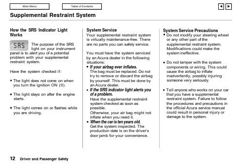
Supplemental Restraint SystemHow the SRS Indicator Light WorksThe purpose of the SRS light on your instrumentpanel is to alert you of a potential problem with your supplemental restraint system.Have the system checked if:The light does not come on whenyou turn the ignition ON (II).The light stays on after the enginestarts.The light comes on or flashes while you are driving.System ServiceYour supplemental restraint system is virtually maintenance-free. There are no parts you can safely service.You must have the system serviced by an Acura dealer in the followingsituations:If your airbag ever inflates.The bag must be replaced. Do not try to remove or discard the airbag by yourself. This must be done byan Acura dealer.If the SRS indicator light alerts you of a problem.Have the supplemental restraint system checked as soon as possible.Otherwise, your air bag might notinflate when you need it.When the car is ten years old.Get the system inspected. The production date is on the driver's door jamb for your convenience.System Service PrecautionsDo not modify your steering wheel or any other part of thesupplemental restraint system.Modifications could make thesystem ineffective.Do not tamper with the system components or wiring. This could cause the airbag to inflateinadvertently, possibly injuringsomeone very seriously.Tell anyone who works on your car that you have a supplementalrestraint system. Failure to follow the procedures and precautions in the official Acura service manual could result in personal injury or damage to the system.Driver and Passenger SafetySupplemental Restraint System, Additional Safety Information Scrapping an entire car that has anuninflated airbag can bedangerous. Get assistance from anAcura dealer if your car must bescrapped.If you sell your car, please be sure totell the new owner that the car has asupplemental restraint system. Alertthem to the information andprecautions in this part of theowner's manual.The seat belts and airbag areobviously important parts of youroccupant protection system.In addition, you should know thatsitting upright, locking the doors, andstowing things properly can alsoincrease your safety and possiblyeven save your life.Seat Back PositionThe seat-backs should be in anupright position for you and yourpassengers to get the mostprotection from the seat belts.If you recline a seat-back, you willreduce the protective capability ofyour seat belt. The farther a seatback is reclined, the greater the riskthat you will slide under the belt in asevere crash and be very seriouslyinjured.For information on how to adjust theseat back, see page 52.CONTINUEDDriver and Passenger SafetyAdditional Safety InformationDoor LocksIt is not safe to leave your car doors unlocked. A passenger, especially a child, could open a door andaccidentally fall out. Also, there is a greater chance of being thrown out of a car during a crash when the doors are not locked.Storing Cargo SafelyBefore you drive, make sure you first securely store any items that could be thrown around the car and hurt someone, or interfere with your ability to operate the controls.Be sure to keep compartment doors closed when the car is moving. If a front passenger hits the door of an open glove box, for example, they could injure his knees.Driver and Passenger SafetyAdditional Safety Information, Child SafetyDriving with PetsLoose pets can be a hazard while you are driving. A loose pet can interfere with your ability to drive the car. In a crash or sudden stop, loose pets or cages can be thrown around inside the car and hurt you. It is also for their safety that pets should be properly restrained in your car.The recommended way to restrain a medium-sized or larger dog is with a special traveling harness. This harness can be secured to the seat with a seat belt. Travel harnesses are available at pet stores.A small dog, cat or other smallanimal will be safest in a rigidly-sided pet carrier. Choose a style that allows you to secure it to the car's seat by routing a seat belt through the carrier's handleFor further information, contact your veterinarian or local animal protection society.Child SafetyChildren depend on adults to protect them. To help make sure we do,every state and Canadian province has laws requiring infants and young children to be properly restrained whenever they ride in a car.CONTINUEDDriver and Passenger Safety。
太尔时代MINI说明书

目录
1.简介.............................................................. 1 1.1 手册使用须知..................................................1 1.2 注意事项 ...................................................... 1 1.2.1 安全....................................................... 1 1.2.2 保护措施................................................... 2
50%之间,如超过此范围,可能会影响成型质量。
2
2.概述
UP!三维打印机的设计理念是简易、便携。只需要几个按键,即使您从来没 有使用过3D打印机,也可以很容易地制造出自己喜欢的模型。该打印机的原理 是首先将ABS材料高温熔化挤出,并在成型后迅速凝固,因而打印出的模型结实 耐用。 2.1 外观
1、打印机前视图
法律声明
我们有权在未通知的情况下对本手册的相关内容进行修改。
我们对于因参照本手册而造成的任何损失(包括后续损失)均不承担责任, 其中包括因印刷错误和其他出版错误造成的损失。在未得到事先书面同意的情况 下,任何人不得对此说明书进行修改、复印或翻译。本手册受版权保护,且本公 司保留对本手册的最终解释权。
12
3.2 使用基本功能 3.2.1 启动程序
点击桌面上的图标
,程序就会按照如下图示打开:
(主操作界面)
3.2.2 载入一个 3D 模型
Mini-Circuits产品说明书
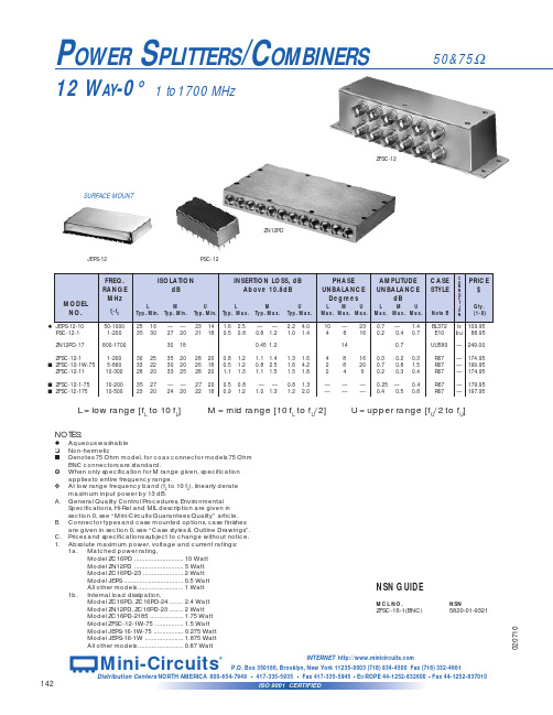
6
0.7
1.15 1.60 1.05 1.30 UU179
C O
PRICE
N N
$
E
C
T
I
Qty.
O N
(1-9)
kf 79.95 kf 139.95
— 172.95 — 182.95 — 172.95 — 189.95 — 189.95
— 349.00 — 295.00 — 295.00 — 265.00
POWER SPLITTERS/COMBINERS
12 WAY-0° 1 to 1700 MHz
50&75Ω
ZFSC-12
SURFACE MOUNT
ZN12PD
JEPS-12
PSC-12
MODEL NO.
u JEPS-12-10 PSC-12-1
FREQ. RANGE
MHz
fL-fU
50-1000 1-200
ZC16PD-24 ZC16PD-900 ZC16PD-960 ZC16PD-960W
650-2400 800-900 890-960 700-1000
ZC16PD-1900 ZC16PD-1900W ZC16PD-23 ZC16PD-2185
1700-1900 1500-2100 1500-2300 1800-2600
25 14 30 20 28 20 26 15
30 20 30 15 32 20 30 16
1.5 2.5 1.9 3.5
3.0 4.2 2.2 4.0
1.1 1.3 0.7 1.1 0.5 0.9 0.4 0.8 0.7 1.0
1.2 1.4 1.0 1.3 0.5 0.9 1.0 1.6 0.9 1.5
MiniRAE 3000操作使用手册2010.10
目录
使用前须知 ................................................................................................................................1 注 意..........................................................................................................................................1 特别提示 ....................................................................................................................................1 警 告..........................................................................................................................................1 标准配置 ....................................................................................................................................2 产品概述 ....................................................................................................................................2 主要部件 ....................................................................................................................................2 技术指标 ....................................................................................................................................3 检测范围及分辨率.....................................................................................................................3 电池充电 ....................................................................................................................................4
mini说明书

车载智能终端使|用|手|册感谢您购买本公司产品,为了更好地使用本产品,在使用之前请认真阅读本说明书,并遵守本书每一章节的操作和注意事项。
声明1.未经本公司同意,不得以任何形式或手段复制、摘抄、翻译本手册的内容。
本公司不断改善产品,所以保留未来修改产品规格、特性及保养维修程序的权利。
2.本使用手册中描述的各项功能部分需要安装选配配件或升级到相应版本固件程序才能使用,部分需要配合系统平台才能使用。
3.本产品在出厂前已经进行充分检测,确认产品能够正常工作并且符合相关要求。
如产品发生故障,本公司除了根据品质保证规定承担维修责任之外,对于用户使用本产品而导致的财产损害和经济损失不承担任何赔偿责任。
目录一、系统概述 (3)二、主要功能 (4)三、接口定义及安装说明 (8)四、配置清单 (11)五、技术参数 (12)六、常见问题 (13)七、售后服务 (13)八、产品保修卡 (15)一、系统概述本车载智能终端是基于国家标准《GB/T 19056汽车行驶记录仪》和交通行业标准《JT/T794-2011道路运输车辆卫星定位系统车载终端技术要求》、《JT/T 808-2011 道路运输车辆卫星定位系统终端通讯协议及数据格式》而研制的一款高性能智能车载产品。
产品内部集成北斗/GPS卫星模块和GSM/GPRS通讯模块以及各种信号传感器,能记录、存储车辆的行驶速度、里程、时间以及有关车辆的各种信息,实现对车辆/司机远程和本地7*24小时立体监控及管理。
能有效地遏制司机的超速、疲劳等违章驾驶行为。
能整体提高公司的管理水平。
能全面客观地记录交通事故时车辆状态和司机行为。
产品深度符合车载行业特色,高度集成了车载行业各特色应用。
具有安装方便、稳定、可靠、性价比高、功耗低等优点。
二、主要功能2.1 数据采集功能2.1.1 车辆速度实时记录车辆速度。
2.1.2 车辆里程实时统计记录车辆里程,可统计总里程。
2.1.3 车辆轨迹实时记录车辆行驶轨迹,含经纬度、高程、方向等信息,可设为定时、定次、定距等采集方式。
浩星轨道迷你电动货物车技术指南说明书

SÉRIE P1.6UTGUIDE TECHNIQUE2DIMENSIONS DU CHARIOTh 14h 3sl 1l ch 13l 2yexm 2A stsyb 5h 14ea 2a 2W aa 2a 2b 10b 5h 3l ch 13xm 2l 1l 2A stb 1b 11b 1b 1131.11.21.31.41.51.61.81.92.12.22.33.13.23.33.43.53.63.74.44.94.154.194.204.214.224.254.324.334.34.14.34.24.355.15.25.35.75.85.106.16.26.36.46.56.66.76.88.110.7C A R A C T ÉR I S T I Q U E SD I S T I N C TP O I D SR O U E SD I ME N S I O N SP E R F O R M A N C E SM O T E U R ÉL E C T R I Q U EConstructeur (abréviation)Désignation constructeurMoteur : électrique (batterie ou réseau), diesel, essence, GPLType d’opérateur : manuel, à conducteur accompagnant, debout, assis, préparateur de commande Capacité nominale/charge nominale Distance du centre de chargeDistance de la charge, entre le centre du pont moteur et les fourches Empattement Poids en serviceCharge par essieu, en charge, avant/arrière Charge par essieu à vide, avant/arrièrePneus : polyuréthane, topthane, NDIIThane, avant/arrière Dimensions des pneus avant Dimensions des pneus arrière Roues supplémentaires (dimensions)Nombre de roues, avant, arrière (x = motrices)Voie, avant Voie, arrière LevageHauteur du timon en position de conduite mini./maxi.Hauteur, fourches abaissées Longueur hors-toutLongueur jusqu’à la face avant des fourches Largeur hors-toutDimensions des fourches ISO 2331Largeur entre les fourches-bras Garde au sol au milieu de l’empattementDimensions de la charge b12 × l6 dans le sens transversal Largeur d’allée pour palettes 1000 x 1 200 dans le sens transversal Largeur d’allée pour palettes 800 x 1 200 dans le sens en longueur Rayon de braquageVitesse de déplacement, en charge/à vide Vitesse de levage, en charge/à vide Vitesse de descente, en charge/à vide Performances en rampe, en charge/à vide Pente maxi. surmontable en charge/à vide Frein de serviceSpécifications du moteur de traction S2 60 min Spécifications du moteur de levage à S3 15 %Batterie selon DIN 43531/35/36 A, B, C, non Tension batterie/capacité nominale K5Poids de la batterieConsommation d’énergie selon le cycle VDI Productivité maximaleConsommation d’énergie en conditions de productivité maximale Type d’unité motriceNiveau de pression sonore à l’oreille de l’opérateurHyster P1.6UT Batterie à conducteur1.660098413304242020324 / 96Polyuréthane 230 x 10078 x 9890 x 401x + 2 / 2480375 / 515120750 / 125078166651471055 / 160 / 115054527-2288215614885.8 / 6.00.03 / 0.0380.04 / 0.036 8 / 20-Generative 1.200.8No 24 / 1501500.25--Courant alternatif CA65Q c x yb 10b 11h 3h 14h 13l 1 l 2 b 1 / b 2s / e / l b 5m 2b 12 × l 6 Ast Ast Wat mm mm mm kg kg kgmm mm mmmm mm mm mm mm mm mm mm mm mm mm mm mm mm mm km/h m/s m/s %%kW kWV / Ah kgkWh/h @Nb de cycles t/hkWh à 1 h (kWh/h)dB (A) SPÉCIFICATIONS DU MODÈLES P1.6UTLe transpalette électrique P1.6UT Hyster associe caractéristiques ergonomiques, performances fiables et technologie peu gourmande en énergie. Ses programmes d’entretien peu contraignants contribuent à augmenter la productivité et à réduire les coûts d’exploitation.PRODUCTIVITÉn Avec le système de commande àcourant alternatif sophistiqué, il n’y aplus de balais de moteur : les besoins de maintenance sont limités.n Le système d’extraction latérale debatterie sur rouleaux réduit auminimum le temps et les effortsnécessaires pour remplacer lesbatteries.n Un clapet de décharge intégré protège le chariot contre les surcharges.n Bouton de déconnexion d’urgence.n Timon long.n Système de recul d’urgence dans la poignée.n Interrupteur de faible vitesse dans la poignée.n Commande progressive de la vitesse.n Sa faible consommation énergétique optimise l’autonomie de la batterie.CONCEPTION OPTIMISÉEn Les roues stabilisatrices sur ressorts renforcent la stabilité latérale sur les sols irréguliers ; elles améliorent les performances du chariot et sa durée de vie.n Les fourches sont en acier formé trèsépais, ce qui leur confère une solidité optimale.nDe par leur conception, les tirants ne peuvent pas se cintrer.n Caches en plastique résistant.Poignée (standard) utilisable de la main gauche et de la main droite FACILITÉ D’ENTRETIENn Technologie CANbus simplifiant le câblage.n Le limiteur de décharge de batterie permet de prolonger la durée de vie de la batterie.n Tous les points de pivotement possèdent des graisseurs et une bague remplaçable, ce qui réduit l’usure des éléments.Galet d’entrée facilitant la manutention Imprimé dans l’UE. Référence : 3991798 Rév.00-09 / 21-HGHYSTER-YALE UK LIMITED opérant sous la dénomination Hyster Europe. Siège social : Centennial House, Building 4.5, Frimley Business Park, Frimley, Surrey GU16 7SG,Royaume-Uni. Immatriculée en Angleterre et au Pays de Galles. Numéro d’immatriculation de la société : 02636775. ©2021 HYSTER-YALE UK LIMITED, tous droits réservés.HYSTER, le logo et le slogan DES PARTENAIRES PUISSANTS. DES CHARIOTS SOLIDES. sont des marques d’HYSTER-YALE Group, Inc.La société Hyster se réserve le droit de modifier ses produits sans préavis. Les chariots élévateurs illustrés peuvent être présentés avec des équipements en option.DES PARTENAIRES PUISSANTS. DES CHARIOTS SOLIDES.TMPOUR LES APPLICATIONS LES PLUS EXIGEANTES, PARTOUT DANS LE MONDENOTICE:La manutention des charges à grandes hauteurs exige une attention particulière.Les opérateurs devront recevoir la formation nécessaire ; ils devront avoir lu et compris les instructions figurant dans le Manuel d’utilisation et les respecter.Toutes les valeurs sont des valeurs nominales auxquelles peuvent s’appliquer des tolérances. Pour de plus amples informations, contactez le constructeur.La société Hyster se réserve le droit de modifier ses produits sans préavis.Certains des chariots élévateurs illustrés peuvent présenter des équipements en option. Ces valeurs peuvent varier selon les diverses configurations.Sécurité. Ce chariot est conforme aux normes européennes en vigueur.Caractéristiques basées sur la norme VDI 2198.HYSTER EUROPECentennial House, Frimley Business Park, Frimley, Surrey, GU16 7SG, Angleterre .Tel: +44 (0) 1276 538500www.hyster.eu*********************/HysterEurope@HysterEurope/HysterEurope。
迷你穿梭说明书
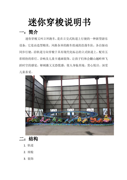
迷你穿梭说明书
一:简介
迷你穿梭又叫立环跑车,是在立交式轨道上行驶的一种新型游乐设备,它是由造型精美、风格各异的跑车组成的浩荡车队,各自驱动同步行驶,沿轨道方向穿梭于具有现代化标志的立式轨道上,配有五彩缤纷的彩灯、音响及儿童卡通画装饰。
让孩子们体会翻山越岭和飞跃时空的感觉,够刺激又无恐慌感,使人身临其境,赏心悦目,深受儿童喜爱。
二:结构
1.轨道
2.座舱
3.装饰
4.电机
5.控制柜
6.顶棚
三:参数
1.占地尺寸:9x16米
2.高度:3米
3.座舱数:12座16座24座36座等
4.电压:380V
5.功率:5kw
四:样式
1.F1赛车
2.雷霆战机
3.宝马车
4.莲花盘
五:安装
弯月飘车整机发货,货到后只需要安装控制柜即可正常运行。
六:维护
1.检查各个线路是否发生破损。
2.检查电气元件的正常使用。
3.滑动位置的润滑。
七:常见故障
1.电机没反应-检查线路是否接通。
2.只旋转不上升。
检查线路是否出现问题。
迷你导航系统入门指南说明书

Getting StartedEach entered letter will appear at the top of the display. Say or select Space to enter a space between words. Say or select Delete to erase a letter entered incorrectly.When entering an address, the system searches the database for words that match the letters you are entering. As a result, you will notice that some letters are no longer available.When the system finds only one entry that matches, it completes the entry of the name for you. If the system finds more than one entry that matches your input, the system displays a list.Tip:If you are unsure of the spelling of a name, enter the letters that you are sure of, and then select List. The system displays a list of names that most closely matches your input.You can choose to have your keyboarddisplayed in alphabetized format asshown below:Or in a regular keyboard (QWERTY)format as shown below:See Keyboard Layout in the Setupscreen (second).HandsFreeLink™If you have a Bluetooth compatible cellphone that is “linked,” then CALL onthe Calculate route to screen isenabled.When you select CALL, the systemdials the number on shown on thescreen. If CALL is not available (darkgray), and your phone is “linked,” thenmake sure the phone has service or thatHFL is not in use; press the HFL BACKbutton.For more information onHandsFreeLink™, see the vehicleOwner’s Manual and the official website ().16Navigation SystemGetting StartedSystem Start-upWhen you turn the ignition to ON (II), it takes several seconds for the navigation system to boot up.The first screen to appear is the navigation system globe screen. The screen then changes to the Disclaimer screen:NOTE:The OK button does not appear immediately. It appears after the software is loaded.Read this disclaimer carefully so youunderstand it before continuing. Push inon the joystick, or touch OK, and themap screen will appear on the display.The “OK” cannot be activated by voice.If you do not press the joystick or touchOK, the screen will go dark after 30seconds. To return to the Disclaimerscreen, press any navigation or voicecontrol button.NOTE:If you do not select OK, and then enterthe Setup or Information screens, someitems are not available, and will showup as darkened buttons (grayed out).See System Function Diagram onpage 20.If you have entered any Calendarreminders, they are displayed after youselect OK.The Calendar reminder screenremains displayed until you select OK,Remind Later or press the CANCELbutton.If you select OK, the reminder will notshow up again. If you wish to have thereminder show up again later in the day,touch the Remind Later button.If you press the CANCEL button, themessage will be displayed the next timeyou start the vehicle.NOTE:The system will display the currentmessage and any older or previouslyunread messages, with the newestmessage listed first.Navigation System 17。
AHRS姿态解算说明(加速度陀螺仪磁力计原理及原始数据分析)
AHRS姿态解算说明(加速度陀螺仪磁力计原理及原始数据分析)给51黑论坛的朋友们分享关于MPU6050的超好文章,介绍姿态解算的入门知识,非常通俗易懂.AHRS俗称航姿参考系统,AHRS由加速度计,磁场计,陀螺仪构成,AHRS的真正参考来自于地球的重力场和地球的磁场~~他的静态终精度取决于对磁场的测量精度和对重力的测量精度,而则陀螺决定了他的动态性能。
这就是AHRS~在这种前提下。
说明AHRS离开了地球这种有重力和磁场环境的时候是没法正常工作的~~本章旨在讲解以下内容1.加速度2.陀螺仪3.磁力计一直想写篇文章关于姿态解算原理的,使用尽量通俗的语句说明如何从加速度计和陀螺仪的数据,融合得到载体的姿态角。
无奈自己的水平有限,一直搁置。
淡泊以明志,宁静以致远.人总是要逼自己做些事,才过得心安理得。
那就拿点时间把这方面的资料整合一下吧。
这篇文章的大部分内容都不是本人原创的,感谢网络上无私奉献的人.在此介绍一下实验的姿态板,新一代的mini AHRS,采用STM32F103单片机进行姿态解算,板子上集成有1.MPU6050,三轴的加速度和陀螺仪2.HMC5883 三轴的磁力计3.BMP180 高精度气压高度计这些传感器都通过I2C接口连接到主控制器STM32.不需要额外的ADC电路,直接通过数字接口就可以读取传感器的当前输出.Mini AHRS硬件框图1 加速度计加速度计顾名思义,就是测量加速度的.那么,我们如何认识这个加速度呢?在此用一个盒子形状的立方体来做模型,认识加速度,如下,盒子内的图像。
如果我们把盒子形状的立方体放在一个没引力场的地方,球会保持在盒子的中间.你可以想象,这个盒子是在外太空,远离任何天体,很难找到这样的地方,就想象飞船轨道围绕地球飞,一切都是在失重状态下。
那么六个壁面感受到的压力都是0.如果我们突然将立方体向左侧移动(我们加快加速,1G =9.8米/ S ^ 2),皮球打在了墙上X-。
miniAHRS传感器的四元数单片机采集与欧拉角转换_周永录(1)

*
( 云南大学 云南省电子计算中心, 云南 昆明 650223 ) 摘要: 以遥控无人飞艇航拍平台的云台随动控制系统为实例, 研究采用新型 1T 单片机 STC12C5412 , 通过 UART 接口与 miniAHRS 传感器相连接, 进行硬件接口电路及软件设计, 解决遥控无人飞艇航拍平台上云台随 动控制系统的三维位姿检测问题 . 关键词: miniAHRS 传感器; 片机; 三维位姿检测; 四元数; 欧拉角转换 中图分类号: TP 391 文献标识码: A 文章编号: 0258 - 7971 ( 2010 ) S2 - 0042 - 07
[1 ]
行从四元数到欧拉角的转换. 1 miniAHRS 传感器和 STC 1T 单片机简介 1. 1 miniAHRS 位姿传感器简介 miniAHRS 位 姿传感器是美国 Innalabs 公司研发生产的一种微
型高性能捷联惯导系统( 图 1 ) , 在陆地、 航海、 航空 以及智能机器人等测控领域中具有较好的应用价 3 轴加速度计和 3 值. 该传感器包括 3 轴陀螺仪、 轴磁通门式磁力计, 其中, 陀螺仪用来测量载体的 绝对角速度, 表征载体角定位的俯仰角 ( Pitch ) 、 横 滚角( Roll) 、 偏航角( Yaw ) 通过陀螺仪的输出信号 计算得出; 加速度计用于系统开始的清零和修正载 体因陀螺仪漂移造成的俯仰和横滚的误差 ; 磁力计 用来进行开始的航向清零和修正因陀螺仪漂移造 miniAHRS 还包含了一个温度 成的航向误差. 此外,
miniAHRS 传感器提供了 2 个相同信号的 RS - 485 通信接口, 2 个接口的引脚信号定义如图 3 2 引脚为电源输入的正端和负端, 所示. 1 , 输入的 4 引脚分别是 电压范围为 5. 1 ~ 5. 7 V ( 80 mA ) . 3 , RS - 485 的 A, B 2 个输入输出信号.
- 1、下载文档前请自行甄别文档内容的完整性,平台不提供额外的编辑、内容补充、找答案等附加服务。
- 2、"仅部分预览"的文档,不可在线预览部分如存在完整性等问题,可反馈申请退款(可完整预览的文档不适用该条件!)。
- 3、如文档侵犯您的权益,请联系客服反馈,我们会尽快为您处理(人工客服工作时间:9:00-18:30)。
MiniIMU引 出 了STM32单 片 机的 两个串 行通 信 口: 1.UART1 做为从的连接端口 2.UART2 做为主的数据输出接口 两个 串行接 口都 有 独立 的发送 和接收 共用 的 可编 程波特 率,最高 达4. 5 Mbits/ s。 在使 用使用 多缓 冲 器配 置的DMA方式,可 以实 现 高速 数据通 信.
更新率
4 - 8000 hz
4 -1000 hz
0.75 - 75 hz 4.5 - 25.5 mS
7 MiniIMU 与PC联机
Mini IMU 配置了一个上位机软件,用于显示各个传感器的输出,和解算后 的姿态。多种显示模式: 1.波 形, 以波形 的形 式 显示 数据值 写时间 的关 系 2.文 字, 文字显 示当 前 的值 3. 3 D显 示 , 解算 后的姿 态数据 可以 使 用3D显示 各个 数据。
3 HMC5883L
I2C
MPU6050
DRDY
I2C
STM32F
概述
HMC5883L 包括最先进的高分辨率 HMC118X 系列磁阻传感器,并附带霍尼韦尔专利的 集成电路包括放大器、自动消磁驱动器、偏差校准、能使罗盘精度控制在 1°~2°的 12 位 模数转换器.简易的 I 2C 系 列总线接口。
与主控制器的连接
H MC5883 L并 没有 直接 和 主控 制器的I 2 C接 口 相 连接 。 而 是与M PU 6 0 5 0的A UXI2 C接 口连 接, 这 样, 有两种 方式 访 问HMC588 3 L的 数 据 。 1 .将M PU60 5 0的A UX接口 设置 成直连 式,S TM3 2 F可 以 通 过I2C直接 访问H M C 5 8 8 3L 2 .开启M P U 6 0 50的A UX接 口为 主控制 器, 通 过AUXI2C接口MPU605 0负 责采 集 H MC5883 L的 采样 结果,并 将结果 存放 在 自己 的FI F O寄存 器中 。S T M 3 2F通过 访问 M PU6050读 取HMC58 8 3的 转 换 结果 。 以 上两 个方式 都可 以 在miniIMU中 实现 ,不 需 要额 外 的增 加或者 是修 改 电路 ,只 需 要设 置MP U 6050相应的 控 制寄 存器。
特点:
1.具有13 1 L S Bs/°/ se c 敏 感 度与 全格感 测范围 为±2 50、 ±500、±1 0 0 0与± 2000°/ s e c 的3轴 角速 度 感测 器(陀螺 仪)。 2.可程式控 制, 且 程式 控 制范 围为±2 g、 ±4g、±8g和 ±1 6g的3轴 加速 器。
MiniIMU Mini IMU AHRS 使用说明
本 章 旨 在 说 明MiniIMU姿 态 仪 的 功 能 和 使 用 方 法 1. MiniIMU的 硬 件 组 成 和 接 口 定 义 2. MiniIMU的 性 能 3.如 何 使 用 电 脑 软 件 与MiniIMU联 机 4.注 意 事 项
与主控制器的连接
M PU605 0通 过I2C接口连接 到主 控 制器S TM 3 2 F。 在 初始化 阶段 ,S T M 3 2将要 设置 M PU605 0的 测量 感度 和 采样 频率, 同时使 能数 据 更新 中断。 之后S TM3 2配 置自 己 的 引脚 为中断 输入 。 这样 在一个 新的 采 样完 成 后MPU605 0产 生中 断, 呼 叫 S TM32读取新 的 数据 。
HM C 5 8 83L的数据准 备引 脚 连接 到了STM32, 通过 查询该 引脚 的 电平 ,判断 是 否有新的转换数据。
4 BMP180
I2C STM32F
概述
BM P 1 8 0是一款高精度、超低能耗的压力传感器,可以应用在移动设备中。它的性能卓越, 绝 对 精 度 最 低 可 以 达 到0 . 0 3 h P a, 并 且 耗 电 极 低 , 只 有3 u A。B M P 1 8 0采 用 强 大 的7 - p i n陶 瓷 无 引 线 芯 片 承 载 (L C C) 超 薄 封 装 , 可 以 通 过I 2 C总 线 直 接 与 各 种 微 处 理 器 相 连 。
与主控制器的连接
B MP085挂接在I 2C总 线上 ,ST M 32可以 直接 访问读 取BMP085上的转 换 数据 。 BM P 0 8 5转换 的时 间 相对 长一些 ,在 读 取气 压时, 需要 的 时间 如 下表
最 长的 时间为2 5 . 5 m s,我们 不希 望程序 在读 取 气压 的 时候 等待转 换完 成 。那 么在 启 动一 次转换 后, 如 何占 用 更少 的CP U而得 知转 换 完成 了呢?
主 要 特 点:
压力范围:300 ... 1100hPa(海拔+9000米...-500米) 量程:300-1100mbar 精度:0.03mbar 输出:I2C接口 数字输出 电源电压:1.8V ... 3.6V(VDDA)
1.62V ... 3.6V(VDDD) 低功耗: 5μA 在 标准模式 高精度: 低 功耗模式下,分辨率为0.06hPa(0.5米) 高 线 性 模 式 下 , 分 辨 率 为0 . 0 2 h P a(0 . 1 7米 ) - 含温度输出 - I 2 C接口 - 温度补偿 反 应 时 间 :7 . 5 m s 待 机 电 流 :0 . 1 µ A 无需外部时钟电路
特点: 1 . 1 2 - b i t A D C 与低干扰 AMR 传感器,能在±8 高斯的磁场中实现 2 毫高斯的分辨率 2 .内置自检功能 3 .内置驱动电路 4.I2C 数字接口 5 .最大输出频率可达160Hz 7 .带置位/复位和偏置驱动器用于消磁、自测和偏移补偿 8 .磁场范围广(+/-8Oe)
6 MiniIMU 性能特点
物理特性
模块工作电压: 4.0V-7.0V
工作电流:
50mA @5.0V
外形尺寸: 37 x 22 x 5 mm
重量(不包括电线): 10g
温度范围: -10C - 60C
数字接口: UART异步串行通信口 TTL电平
工作时功 耗 :2 5 0 m W
传感器特性
三轴陀螺仪 三轴加速度 三轴磁场 气压高度计
2 MPU6050
I2C BUS
FSYNC
STM32F
INT
概述
MPU-6 0 5 0为 全 球首例 整合 性6轴 运动 处理 组 件, 相 较于 多组件 方案 , 免除 了组合 陀螺仪与加速器时之轴间差的问题,减少了大量的包装空间。
M P U -6000的角速 度全格 感测范 围为 ±2 5 0、 ±5 00、 ±1000与±20 00°/ se c (dps), 可准 确追緃 快速 与 慢速 动作, 并且 , 用户 可程式 控制 的 加速 器 全格 感测 范围 为 ±2g、±4 g±8 g与 ±1 6g。 产品 传输可 通过 最 高至4 00 k H z的I 2C总线。
启动时间 最大量程 最小量程
100ms ± 2 , 0 0 0度/秒
± 2 5 0度/秒
100ms ±16G ±2G
50ms ± 8高斯 ± 1高斯
10ms 300-1100hPa 300-1100hPa
A D C位 数
16 Bit
16 Bit
12 Bit
16 Bit
分 辨 率(量程最大时) 16.4 LSB/(º/s) 2,048 LSB/g 4.35 milli-gauss 0.01hPa 分 辨 率(量程最小时) 131 LSB/(º/s) 16,384 LSB/g 0.73 milli-gauss 0.01hPa
串口状态
下位机的姿态解算率
数据波形图
开 启3 D
高度和温度图型显示
数据上传速率
当前值
系统信息
航向罗盘
地平仪
开 启3 D姿 态 显 示
数据通信协议
要与上位机通信,需要通信协议的支持。固定的帧格式和字节数都是指定 的。上位机将通过已知的协议进行解帧并把相应的数据更新到波形、文字和 3 D显 示 。 在这个协议里面,只有两种帧从下位机发送到上位机: 1.原 始 的传 感 器ADC数 据 2.解 算 后的 姿 态角 和气压 高度 原始 的 传感 器ADC数 据 是指 ,直接 从传 感 器读 取出来 的测 量 值,ADC转换 的结 果。没有经过解算处理 解算后的姿态角和气压高度是指,将得到各个传感器值进行解算,得到目标载 体当前的姿态,俯仰角,滚转角,航向角等数据 这两 个 帧可 以 独立 发送。 比如 , 只更 新原始 的ADC数 据, 或 者是 只更新 解算 后 的数据,这都是允许的。
HMC5883
3轴 地磁传感器
U A RT数 据 输 出 S W D调 试 接 口 L E D状 态 指 示
BMP180
气压高度计
1 STM32F103
MiniIMU 的 主控 制芯 片 选用 了STM32F103T8,ARM 32-bit Cortex™-M3 内 核, 它有64KB的 闪存存 储器 , 和20KB的 运行内 存。7通 道 的DMA,7个 定时 器 , 通过 板子上 的8M晶 体 和STM32内部 的PLL, 控制器 可以 运 行在72M的 主频 上,对 于姿态解算这种需要大量数学运行的程序,更快的处理速度可以做更多的解算 优化。
HMC5883L 采用霍尼韦尔各向异性磁阻(AMR)技术,该技术领先于其他磁传感器技术。 这 些 各 向 异 性 传 感 器 具 有 在 轴 向 高 灵 敏 度 和 线 性 高 精 度 的 特 点.传 感 器 具 有 的 对 正 交 轴 的 低 灵敏度的固相结构能用于测量地球磁场的方向和大小,其测量范围从毫高斯到 8 高斯 ( g a u s s )。 霍尼韦尔的磁传感器在低磁场传感器行业中是灵敏度最高和可靠性最好的传感 器。
