Checkpoint12400参数表
CheckPoint产品介绍
©2012 Check Point Software Technologies Ltd. [PROTECTED] — All rights reserved. | 6
各种型号– 适用于任何部署规模!
Branch
(< 250 users)
Small
(< 500 users)
Medium
(< 1,000 users)
Large
(< 5,000 users)
X-Large
(< 10,000 users)
* Sizing recommendation
©2012 Check Point Software Technologies Ltd. [PROTECTED] — All rights reserved. | 7
Check Point 4000 Appliances (3 Models 4200/4600/4800)
Enterprise Grade ▪ 3 to 11 Gbps firewall throughput ▪ 2 to 6 Gbps IPS throughput
Check Point 12000 Appliances (3 Models 12200/12400/12600)
国际国内用户
©2012 Check Point Software Technologies Ltd. [PROTECTED] — All rights reserved. | 5
8种常见型号
Check Point 2200 Appliance
The Small Office – Desktop Model ▪ 3 Gbps firewall throughput ▪ Less than $4,000
容错服务器参数
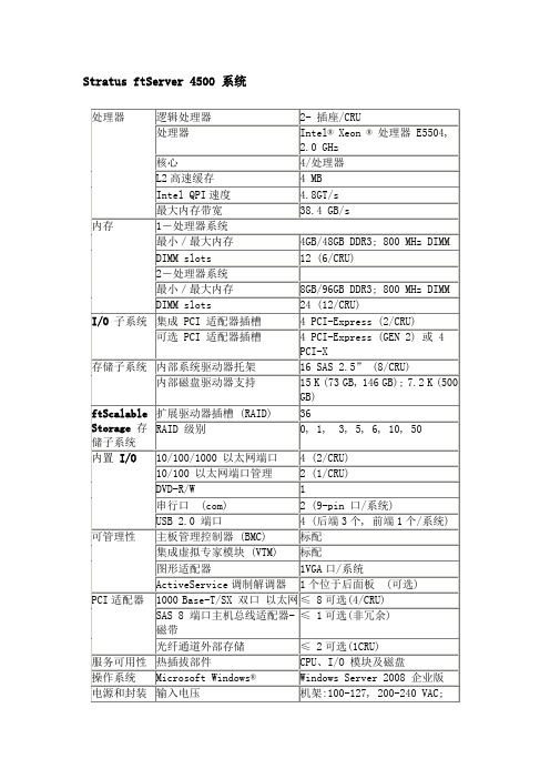
内部磁盘驱动器支持
15 K (73 GB, 146 GB); 7.2 K (500 GB)
ftScalable Storage存储子系统
扩展驱动器插槽 (RAID)
36
RAID 级别
0, 1, 3, 5, 6, 10, 50
内置I/O
10/100/1000 以太网端口
4 (2/CRU)
10/100 以太网端口管理
2 (1/CRU)
DVD-R/W
1
串行口 (com)
2 (9-pin 口/系统)
USB 2.0 端口
4 (后端3个, 前端1个/系统)
可管理性
主板管理控制器 (BMC)
标配
集成虚拟专家模块 (VTM)
标配
图形适配器
1VGA口/系统
ActiveService调制解调器
内存
最小/最大内存
8 GB/96 GB DDR3; 1066 MHz DIMM
DIMM slots
24 (12/CRU)
I/O子系统
集成 PCI 适配器插槽
4 PCI-Express (2/CRU)
可选 PCI 适配器插槽
4 PCI-Express (GEN 2) 或 4 PCI-X
存储子系统
内部系统驱动器托架
电源和封装
输入电压
机架:100-127, 200-240 VAC; 50Hz, 60 Hz
机架系统尺寸 (长×宽×高)
76.5 cm x 44.5 cm x 17.8 cm (4U)含边框和调制解调器
重量(全配置含导轨)
机架:54.43 kg (120 lbs) 含导轨
Checkpoint4400参数表

主要特点
223 SecurityPower 5 Gbps 防火墙吞吐量 3.5Gbps IPS 吞吐量 多达 12 个 10/100/1000Base-T 端口 多达 4 个 1GbE 光纤端口 1 个机架单元设备
主要优点
入门级企业安全设备
通过一台设备提供保证你的网络安全 所需的一切 通过一个集成管理控制台简化管理
Check Point 的新型设备将快速联网技术与高性能多核能力结合在一起,提供最高 层次的安全性,同时不会降低网络速度,保证你的数据、网络和员工安全。每种 设备针对软件刀片架构而优化,能够运行任意软件刀片组合,通过将多种安全技 术合并成一种集成解决方案而为每个网络站点的任意业务提供具有灵活性和精确 性的安全等级。
Check Point 4400 设备
4400
企业级安全设备(223 SPU/5Gbps)— 快速联
网以及光纤和铜缆连接
选项
Check Point 4400 设备
目前,企业网关不仅是防火墙。它是为应对日益增多的复杂威胁而提供的一款安 全设备。作为企业安全网关,它必须使用多种技术来控制网络访问,检测复杂攻 击,并提供其它安全能力,如数据丢失防护和防御基于 Web 的威胁等。而智能手 机和平板电脑等移动设备的扩散以及新型流媒体、社交网络和 P2P 应用软件则需 要更大的连接容量和新的应用控制技术。最终,企业向私有云和公共云服务的转 型从各个方面改变了公司的边界,这需要更强的性能和额外的安全解决方案。
链路故障检测
尺寸 外壳:1U 标准(宽 x 长 x 高):17.25 x 12.56 x 1.73 英寸 公制(宽 x 长 x 高):438 x 320 x 44 毫米 重量:7.5 千克(16.53 磅)
Checkpoint12400参数表
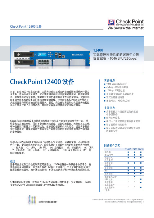
概述 鉴于高安全软件刀片性能和高度可升级性,12400设备是一种数据中心级平台,提 供高级冗余和模块化。除了两个板载1 GB铜以太网端口,三个可用扩展槽,可用于 配置各种网络选项,如1 GB以太网铜、1 GB以太网光纤和10 GB以太网光纤连接。
Checkpoint4800参数表

Check Point 4800设备Check Point 4800 设备目前,企业网关不仅是防火墙。
它是为应对日益增多的复杂威胁而提供的一款安全设备。
作为企业安全网关,它必须使用多种技术来控制网络访问,检测复杂攻击,并提供其它安全能力,如数据丢失防护和防御基于网络的威胁等。
智能手机和平板电脑等移动设备的扩散以及新型数据流、社交网络和P2P应用软件要求扩大连接容量和采用新的应用控制技术。
最后,向企业私有云和公共云服务的转型从各个方面改变了公司的边界,要求扩大容量和提供其它安全解决方案。
Check Point的新型设备将快速联网技术与高性能多核能力结合在一起,提供最高层次的安全性,同时不会降低网络速度,保证你的数据、网络和员工安全。
每种设备针对软件刀片架构而优化,能够运行任意软件刀片组合,通过将多种安全技术合并成一种集成解决方案而为每个网络站点的任意业务提供灵活性和准确的安全等级。
每种Check Point设备支持Check Point的3D安全远景规划,后者将策略、人和执行结合在一起,提供无法攻克的防护,该设备针对下列软件刀片的任意组合进行优化:(1)防火墙,(2)VPN,(3)IPS,(4)应用控制,(5)移动接入,(6)DLP,(7)URL过滤,(8)反病毒,(9)反垃圾邮件,(10)身份意识以及(11)高级联网和集群。
概述Check Point 4800设备以1U波形因数的领先性能提供完整的增强安全解决方案。
除了八个板载1 GB铜以太网端口,4800还具有一个扩展槽,可选装附加的四个或八个1 GB铜以太网端口、两个或四个1 GB光纤以太网端口或两个10 GB光纤以太网端口。
4800提供623个SecurityPower单元,防火墙吞吐量11 Gbps,IPS吞吐量6 Gbps,具有极高的性价比。
主要特点623 SecurityPower 11 Gbps 防火墙吞吐量 6 Gbps IPS吞吐量多达16个10/100/1000Base-T端口 多达4个1GbE或2个10GbE光纤端口 备选远程管理(LOM)主要优点为多软件刀片性能而优化的中型企业级设备通过一台设备提供保证你的网络安全所需的一切通过一个集成管理控制台简化管理 通过保证远程访问以及站点对站点通信的安全保证数据安全通过可扩展软件刀片架构提供全面安全并防护不断出现的威胁网关软件刀片防火墙IPsec VPN移动接入(5个用户) 高级联网和集群身份识别IPS 应用控制数据丢失防护**URL 过滤**反病毒和反恶意软件 **反垃圾邮件***备选Check Point 4800设备SECURITYPOWER到目前为止,安全设备是根据每种安全功能的具体性能衡量指标(通常在最佳实验室测试条件下)以及具有一条规则的安全策略而选择的。
Modicon M241 产品数据手册说明书

i s c l a im e r : T h i s d o c u m e n t a t i o n i s n o t i n t e n d e d a s a s u b s t i t u t e f o r a n d i s n o t t o b e u s e d f o r d e t e r m i n i n g s u i t a b i l i t y o r r e l i a b i l i t y o f t h e s e p r o d u c t s f o r s p e c i f i c u s e r a p p l i c a t i o n sProduct datasheetCharacteristicsTM241CE40Tcontroller M241 40 IO transistor PNP EthernetMainRange of productModicon M241Product or component type Logic controller [Us] rated supply voltage 24 V DCDiscrete input number 24 discrete input including 8 fast input conforming to IEC 61131-2 Type 1Discrete output type TransistorDiscrete output number 16 transistor including 4 fast output Discrete output voltage 24 V DC for transistor outputDiscrete output current0.1 A with Q0...Q3 terminal(s) for fast output (PTO mode)0.5 A with Q0...Q15 terminal(s) for transistor outputComplementaryDiscrete I/O number40Number of I/O expansion module 7 (local I/O architecture)14 (remote I/O architecture)Supply voltage limits 20.4...28.8 V Inrush current<= 50 APower consumption in W 32.6...40.4 W with max number of I/O expansion module Discrete input logic Sink or source Discrete input voltage 24 V Discrete input voltage type DCVoltage state1 guaranteed >= 15 V for input Current state 1 guaranteed >= 2.5 mA for input >= 5 mA for fast input Voltage state 0 guaranteed <= 5 V for input Current state 0 guaranteed <= 1 mA for input<= 1.5 mA for fast input Discrete input current 7 mA for input10.7 mA for fast input Input impedance4.7 kOhm for input2.81 kOhm for fast inputResponse time<= 2 µs turn-on operation with I0...I7 terminal(s) for fast input<= 2 µs turn-off operation with I0...I7 terminal(s) for fast input<= 2 µs turn-on operation with Q0...Q3 terminal(s) for fast output<= 2 µs turn-off operation with Q0...Q3 terminal(s) for fast output50 µs turn-on operation with I0...I15 terminal(s) for input50 µs turn-off operation with I0...I15 terminal(s) for input<= 34 µs turn-on operation with Q0...Q15 terminal(s) for output<= 250 µs turn-off operation with Q0...Q15 terminal(s) for outputConfigurable filtering time 1 µs for fast input12 ms for fast input0 ms for input1 ms for input4 ms for input12 ms for inputDiscrete output logic Positive logic (source)Output voltage limits30 V DCCurrent per output common 2 AOutput frequency<= 20 kHz for fast output (PWM mode)<= 100 kHz for fast output (PLS mode)<= 1 kHz for outputAccuracy+/- 0.1 % at 20...100 Hz for fast output+/- 1 % at 100 Hz...1 kHz for fast outputLeakage current<= 5 µA for outputVoltage drop<= 1 VTungsten load<= 2.4 WProtection type Short-circuit and overload protection with automatic resetReverse polarity protection for fast outputShort-circuit protectionReset time10 ms automatic reset output12 s automatic reset fast outputMemory capacity8 MB for program64 MB for system memory RAMData backed up128 MB built-in flash memory for backup of user programsData storage equipment<= 32 GB SD card optionalBattery type BR2032 lithium non-rechargeable, battery life: 4 yrBackup time 2 years at 25 °CExecution time for 1 KInstruction0.3 ms for event and periodic task0.7 ms for other instructionApplication structure8 external event tasks4 cyclic master tasks3 cyclic master tasks + 1 freewheeling task8 event tasksRealtime clock WithClock drift<= 60 s/month at 25 °CPositioning functions PWM/PTO function 4 channel(s) (positioning frequency: 100 kHz)Counting input number 4 fast input (HSC mode)Control signal type A/B signal at 100 kHz for fast input (HSC mode)Pulse/Direction signal at 200 kHz for fast input (HSC mode)Single phase signal at 200 kHz for fast input (HSC mode)Integrated connection type USB port with connector mini B USB 2.0Ethernet with connector RJ45Non isolated serial link "serial 1" with connector RJ45 and interface RS232/RS485Non isolated serial link "serial 2" with connector removable screw terminal block and interface RS485 Supply Serial link supply "serial 1" at 5 V, 200 mATransmission rate 1.2...115.2 kbit/s (115.2 kbit/s by default) for bus length of 15 m - communication protocol: RS4851.2...115.2 kbit/s (115.2 kbit/s by default) for bus length of 3 m - communication protocol: RS232480 Mbit/s for bus length of 3 m - communication protocol: USB10/100 Mbit/s - communication protocol: EthernetCommunication port protocol Modbus non isolated serial link with master/slave methodPort Ethernet 1 - 10BASE-T/100BASE-TX port with copper cable supportCommunication service FDRDownloadingIEC VAR ACCESSMonitoringNGVLProgrammingUpdating firmwareSMS notificationsDHCP server (via TM4 Ethernet switch network module)DHCP client (embedded Ethernet port)SNMP client/serverFTP client/serverSQL clientSend email from the controller based on TCP/UDP libraryModbus TCP client I/O scannerEthernet/IP originator I/O scanner (embedded Ethernet port)Ethernet/IP target, Modbus TCP server and Modbus TCP slaveLocal signalling 1 LED green for SD card access (SD)1 LED red for BAT1 LED green for SL11 LED green for SL21 LED per channel green for I/O state1 LED red for I/O error (I/O)1 LED red for bus fault on TM4 (TM4)1 LED green for Ethernet port activity1 LED red for module error (ERR)1 LED green for PWR1 LED green for RUNElectrical connection Removable screw terminal block for inputs and outputs (pitch 5.08 mm)Removable screw terminal block for connecting the 24 V DC power supply (pitch 5.08 mm) Cable length<= 50 m unshielded cable for input<= 10 m shielded cable for fast input<= 3 m shielded cable for fast output<= 50 m unshielded cable for outputInsulation500 V AC between fast input and internal logicNon-insulated between inputs500 V AC between output and internal logic500 V AC between fast output and internal logicNon-insulated between outputs500 V AC between input and internal logic500 V AC between output groups500 V AC between supply and internal logicNon-insulated between supply and groundMarking CESurge withstand 1 kV for power lines (DC) in common mode conforming to EN/IEC 61000-4-51 kV for shielded cable in common mode conforming to EN/IEC 61000-4-50.5 kV for power lines (DC) in differential mode conforming to EN/IEC 61000-4-51 kV for relay output in differential mode conforming to EN/IEC 61000-4-51 kV for input in common mode conforming to EN/IEC 61000-4-51 kV for transistor output in common mode conforming to EN/IEC 61000-4-5Web services Web serverMaximum number of connections8 connection(s) for Modbus server8 connection(s) for SoMachine protocol10 connection(s) for web server4 connection(s) for FTP server16 connection(s) for Ethernet/IP target8 connection(s) for Modbus clientNumber of slave16 Ethernet/IP64 Modbus TCPCycle time10 ms 16 Ethernet/IP64 ms 64 Modbus TCPMounting support Top hat type TH35-15 rail conforming to IEC 60715Top hat type TH35-7.5 rail conforming to IEC 60715Plate or panel with fixing kitHeight90 mmDepth95 mmWidth190 mmProduct weight0.62 kgEnvironmentStandards CSA C22.2 No 142ANSI/ISA 12-12-01UL 1604CSA C22.2 No 213EN/IEC 61131-2 : 2007Marine specification (LR, ABS, DNV, GL)UL 508Product certificationsCSA cULus RCMIACS E10Resistance to electrostatic discharge 4 kV on contact conforming to EN/IEC 61000-4-28 kV in air conforming to EN/IEC 61000-4-2Resistance to electromagnetic fields10 V/m (80 MHz...1 GHz) conforming to EN/IEC 61000-4-33 V/m (1.4 GHz...2 GHz) conforming to EN/IEC 61000-4-31 V/m (2 GHz...3 GHz) conforming to EN/IEC 61000-4-3Resistance to fast transients2 kV for power lines conforming to EN/IEC 61000-4-41 kV for Ethernet line conforming to EN/IEC 61000-4-41 kV for serial link conforming to EN/IEC 61000-4-41 kV for input conforming to EN/IEC 61000-4-41 kV for transistor output conforming to EN/IEC 61000-4-4Resistance to conducted disturbances,induced by radio frequency fields10 V (0.15...80 MHz) conforming to EN/IEC 61000-4-63 V (0.1...80 MHz) conforming to Marine specification (LR, ABS, DNV, GL)10 V (spot frequency (2, 3, 4, 6.2, 8.2, 12.6, 16.5, 18.8, 22, 25 MHz)) conforming to Marine specification (LR, ABS, DNV, GL)Electromagnetic emissionConducted emissions, test level: 120...69 dBµV/m QP, condition of test: power lines (radio frequency:10...150 kHz) conforming to EN/IEC 55011Conducted emissions, test level: 79...63 dBμV/m QP, condition of test: power lines (radio frequency:150 kHz...1.5 MHz) conforming to EN/IEC 55011Conducted emissions, test level: 63 dBμV/m QP, condition of test: power lines (radio frequency:1.5...30 MHz) conforming to EN/IEC 55011Radiated emissions, test level: 40 dBμV/m QP with class A (radio frequency: 30...230 MHz)conforming to EN/IEC 55011Radiated emissions, test level: 47 dBμV/m QP with class A (radio frequency: 230 MHz...1 GHz)conforming to EN/IEC 55011Immunity to microbreaks10 msAmbient air temperature for operation -10...55 °C for horizontal installation -10...50 °C for vertical installation Ambient air temperature for storage -25...70 °CRelative humidity 10...95 % without condensation in operation 10...95 % without condensation in storage IP degree of protection IP20 with protective cover in place Pollution degree 2Operating altitude 0...2000 m Storage altitude 0...3000 mVibration resistance3.5 mm (vibration frequency: 5...8.4 Hz) on symmetrical rail 3 gn (vibration frequency: 8.4...150 Hz) on symmetrical rail 3.5 mm (vibration frequency:5...8.4 Hz) on panel mounting 3 gn (vibration frequency: 8.4...150 Hz) on panel mounting Shock resistance15 gn for 11 msOffer SustainabilitySustainable offer status Green Premium productRoHS (date code: YYWW)Compliant - since 1330 - Schneider Electric declaration of conformity Schneider Electric declaration of conformity REAChReference not containing SVHC above the threshold Reference not containing SVHC above the threshold Product environmental profileAvailableProduct environmental Product end of life instructionsAvailableEnd of life manualDimensions Drawings DimensionsClearanceMounting PositionAcceptable MountingNOTE: Expansion modules must be mounted above the logic controller.Incorrect MountingDirect Mounting On a Panel Surface Mounting Hole LayoutDigital InputsWiring Diagram(*) :Type T fuse(1) :The COM0, COM1 and COM2 terminals are not connected internally (A) :Sink wiring (positive logic)(B) :Source wiring (negative logic)Fast Input Wiring (I0...I7)Fast Transistor OutputsWiring Diagram(*) :Type T fuse(1)The V0+, V1+, V2+ and V3+ terminals are not connected internally.(2)The V0-, V1-, V2- and V3- terminals are not connected internally.Transistor OutputsWiring Diagram(*) :Type T fuse(1) :The V1+, V2+ and V3+ terminals are not connected internally.(2) :The V1–, V2– and V3– terminals are not connected internally.USB Mini-B ConnectionEthernet Connection to a PC。
VIS Infinera 12x1 4x1 VCSEL芯片数据表说明书

No. 120314-Rev 1.0March 2012Product CParameter Typical NotesEmission Wavelength 850 nmavailable from 835 – 860 nm Data RateUp 28 Gbit/s per channel Rise time (20% to 80%) < 15 ps Threshold Current 1.0 mA Peak Output Power7 mWProduct Description Product DescriptionThese compact and very high modulation rate top-emitting GaAs-based vertical cavity surface emitting laser (VCSEL) chips and 1xN (N=1, 2, 4, 12, etc.) arrays are available as engineering samples for use in the development and evaluation of opticalinterconnections, optical backplanes and integrated waveguides, and next-generation optical data communications systems. The VCSELs are contacted on the top-surface individually using ground-source (GS) microprobes, wire bonds, or flip-chip bonds.DatasheetFeatures· available in 4x1 and 12x1configuration · up to 28 Gbit/s per channel · high temperature stability · standard pitch size 250 µm · high device-to-device uniformity Applications· 40/100 Gbit/s Ethernet · Infiniband FDR · OTU4 100 Gbit/s· Proprietary optical interconnects · Active Optical Cables (AOC)VI Systems GmbH Hardenbergstrasse 7 D-10623 Berlin28 Gbit/s VCSELs and VCSEL Arrays (850 nm)Product Code:V25B-850C 1x1 V25B -850C4 4x1 arrayV25B -850C12 12x1 arrayPreliminarySample image only. Actual product may vary.DatasheetV25B-850CPreliminary Electro Optical SpecificationsAbsolute Maximum RatingsAll product specifications and descriptions are subject to change without notice. VI Systems GmbH Hardenbergstrasse 7 D-10623 Berlin No. 120314-Rev 1.0 March 2012No. 120314-Rev 1.0March 2012DatasheetV15-850CPreliminaryVI Systems GmbH Hardenbergstrasse 7 D-10623 BerlinNo. 120314-Rev 1.0March 2012All product specifications and descriptions are subject to change without notice.Pleasecontactoursalesdepartmentforadditionalinformationandtoreceiveaquotation:*********************VI Systems GmbH Hardenbergstrasse 7 D-10623 BerlinThe V25B-850C has been tested to meet specifications outlined in this data sheet at room temperature. However, it has not undergone full qualification testing or characterization and therefore may not meet the performance specifications over all extremes.Limited Qualification NotificationVI Systems GmbH Hardenbergstrasse 7 10623 BerlinTel.: +49 30 3083143 30 Fax: +49 30 3083143 59 *********************DatasheetV25B-850C。
checkpoint

24-
端口
16Power-1 5070
8-
12400 设备
两倍端口 密度
端口
UTM-1 3070
超过3.5M 并发 连接数*
2百万
x3
1-
x2
12200 设备
©2011 Check Point Software Technologies Ltd.
|
[PROTECTED] – All rights reserved
12200 VSX Appliance
可整合 250 个安全网关
12400 VSX Appliance 结合防火墙、VPN、IPS 和 URL 过滤
12600 VSX Appliance
利用 37 端口密度可保护更多网络 21400 VSX Appliance
©2011 Check Point Software Technologies Ltd. | [PROTECTED] – All rights reserved
带铜和光纤连接选项的入门企业级产品 是早期型号端口数量的两倍
2200
4200
4600
4800
12200 12400 12600 21400
| [PROTECTED] – All rights reserved
©2011 Check Point Software Technologies Ltd.
0.6 M
5 80 GB
企业级桌面型号中领先的性价比 3倍磁盘空间,存储更多本地日志记录
2200
4200
4600
4800
12200 12400 12600 21400
| [PROTECTED] – All rights reserved
Check Point Web网关安全设备介绍

CheckPointWeb网关安全设备介绍今日对网络的使用不仅包括网站,而且还包括应用程序及其功能,但这些使用都可能会危及公司的安全、增加接触恶意软件的机会以及影响工作效率。
企业的不同用户都拥有不同的业务需求,并且安全策略必须支持这些需求,而不是阻碍它们。
例如,人力资源可能需要使用LinkedIn进行招聘活动,而销售代表可能会使用Facebook与客户和合作伙伴保持联系。
如今的安全经理如何才能知道员工应该和不应该访问哪些网站和应用程序?防止恶意下载是安全Web访问的另一个重要功能。
根据卡巴斯基2012年的恶意软件统计数据,91%的攻击都是通过恶意的URL所发起。
因此,企业必须保护自己免遭这种流行的攻击途径。
传统的Web安全解决方案主要侧重于根据URL过滤网站。
这些解决方案都具有不是基于URL的应用程序的有限范围或需要比URL级别进一步的粒度。
为了能够完全控制互联网的使用,客户发现自己正在管理两个单独的解决方案-需要加倍努力在企业中维持策略、分析并监控互联网的使用情况。
主要功能:§一台专用设备便可集成URL过滤、应用程序控制、防病毒软件、身份识别感知和分析以及报告§统一控制互联网的各个方面-按照相同策略控制应用程序和站点§拥有4,700多个应用程序、240,000多个小组件和130多个类别的最大应用程序库§基于云的站点类别不断更新70多个类别的2亿多个站点§UserCheck为用户提供有关互联网风险和公司政策的知识§单一的统一事件控制台增加了对所有安全性的可见性§策略和报告中的用户和用户组粒度主要优点:§通过控制使用应用程序和访问网站充分利用Web2.0的强大功能§识别并阻止从网站下载恶意文件§监控、分析和报告Web访问及应用程序使用情况§集成CheckPoint安全管理以获取更好的控制§保护所有基于Web的活动的唯一解决办法是使用统一的控制、执行和报告CheckPoint通过提供使用我们最强大的Web安全功能组合所构建的专用安全Web网关设备,令安全使用Web2.0变得更加容易,其中包括:§URL过滤用于控制网站访问§应用程序控制用于控制应用程序使用情况§防病毒软件用于识别并拦截恶意软件§身份识别感知用于为用户和群组定义策略§SmartEvent用于全方位了解所有Web用户和活动§统一策略涵盖了所有Web、应用程序、用户和机器CheckPointWeb网关安全设备具有灵活的部署选项,包括适合分支机构和小型办公室,中型、大型和特大型企业的多种型号的独立专用设备,以及适用于任何安全网关的安全Web软件包。
check point 5800参数
check point 5800参数
以下是Checkpoint 5800防火墙的一些常见参数:
1. 尺寸与重量:
- 尺寸:44.5厘米(W)x 43.4厘米(D)x 4.35厘米(H) - 重量:5.81公斤
2. 处理能力:
- 最大处理容量:57 Gbps
- 最大连接数:8,000,000
- 最大隧道数:2,000
- 最大安全对话数:1,000,000
3. 端口:
- 6个千兆以太网端口
4. 安全功能:
- 支持VPN
- 支持防火墙功能
- 支持入侵预防系统(IPS)
- 支持抗DDoS功能
- 支持反病毒和反恶意软件功能
5. 功耗:
- 典型功耗:76.8瓦特
- 最大功耗:93.5瓦特
以上参数仅供参考,具体参数可能根据不同的型号和软件版本而有所不同。
建议在购买前咨询厂家或查阅官方文档以获取最准确的参数。
RT424012中文资料
元器件交易网
Ordering Information
Typical Part Number B RT
1
3
1. Basic Series: RT = Miniature, printed circuit board relay.
2. Enclosure: 1 = 1 pole 12A, Pinning 3.5mm, flux-tight (Code 1). 3 = 1 pole 16A, Pinning 5mm, flux-tight (Code 3). 4 = 2 pole 8A, Pinning 5mm, flux-tight (Code 5).
4. Contact Material: 4 = Silver-nickel 90/10 (standard stock).
1 = Silver cadmium Oxide (Special order)
5. Coil Voltage: 005 = 5VDC 006 = 6VDC
009 = 9VDC 012 = 12VDC
Operate Data @ 25°C
Must Operate Voltage(DC): 70% of nominal. Must Release Voltage(DC): 10% of nominal. Operate Time (Excluding Bounce):
7 ms, typ., 15ms max. at nom. voltage. Release Time (Excluding Bounce):
RT series (DC Coil)
16 Amp PC Board Miniature Relay
Meets VDE 10mm Spacing, 5KV Dielectric
迈瑞BS-400使用说明书(一)
迈瑞BS-400使用说明书(一)BS-400全自动生化分析仪Chemistry AnalyzerOperation Manual知识产权本使用说明书及其对应产品的知识产权属于深圳迈瑞生物医疗电子股份有限公司(以下简称“迈瑞公司”)。
? 2007 深圳迈瑞生物医疗电子股份有限公司版权所有未经迈瑞公司书面同意,任何个人或组织不得复制、修改或翻译本使用说明书的任何部分。
,,,,,,,RealTF,TrackWB,TrueTCR,Q-pick,AutoOLC,iVision,DBF,DRF,RDA,DRA,DFS、SyncNavi、GQ-Ana、One-touchIP、Holo-IS、Opt-VRA、SuperVE-Cine、NFP-DSC、iTouch、iStation、BeneView、SmarTemp是迈瑞公司的注册商标或者商标。
声明迈瑞公司对本使用说明书拥有最终解释权。
在满足下列全部要求的情况下,迈瑞公司才认为应对产品的安全性、可靠性和性能负责,即:1 装配操作、扩充、重调、改进和修理均由迈瑞公司认可的人员进行;2 有关的电气设备符合国家标准;3 产品操作按照本使用说明书进行。
维修服务免费服务范围:凡符合迈瑞公司保修服务条例范围规定的产品皆可享受免费服务。
收费服务范围:1 凡超出迈瑞公司保修服务条例范围规定的产品,迈瑞公司将实行收费服务;2 即使在保修期内,由于以下原因造成产品需要维修之情况:人为损坏;使用不当;电网电压超出产品规定范围;不可抗拒的自然灾害;更换未经迈瑞公司许可的配件、耗材或由非迈瑞公司授权人员维修机器。
退货程序确需向迈瑞公司退货,请遵循以下步骤:1 取得退货权:与迈瑞公司售后服务单位联系,告之迈瑞产品系列编号,此系列编号已标于外装运箱上,若系列编号非清晰可辨,退货不予接受。
请注明产品型号、系列号,简述退货原因。
2 运费:产品运往迈瑞公司维修,用户须承担运费(包括海关费用)。
售后服务单位深圳迈瑞生物医疗电子股份有限公司售后服务部深圳市南山区南油大道新能源大厦4北半层518054 邮政编码:95105652 24小时服务热线:+86 755 26052668 电话:+86 755 26492815 传真:警告:本系统仅限于经迈瑞公司或迈瑞公司的代理商培训的检验专业人员、医生或实验员操作使用。
Agilent U1240系列手持数字多功能表数据表说明书
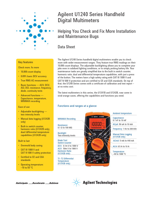
Agilent U1240 Series Handheld Digital MultimetersHelping You Check and Fix More Installation and Maintenance BugsData SheetThe Agilent U1240 Series handheld digital multimeters enable you to check more with wider measurement ranges. They feature true RMS readings on their 10,000-count displays. The adjustable backlighting allows you to complete your jobs even in subdued lighting conditions, or to simply prolong battery life. Your maintenance tasks are greatly simplified due to the built-in switch counter, harmonic ratio, dual and differential temperature capabilities, with just a press of the button. The meters have a high safety rating with CAT III 1000 V and CAT IV 600 V protection and are certified to CE and CSA standards. On top of that, the U1240 Series comes with a certificate of calibration and test report – at no extra cost.The latest multimeters in this series, the U1241B and U1242B, now come in vivid orange cases, offering the capabilities and functions you need.Key featuresCheck more, fix more • 10,000-count display • 0.09% basic DCV accuracy • True RMS AC measurement • Basic functions — ACV, DCV, ACI, DCI, resistance, frequency, diode, continuity tests • Advanced functions — Capacitance, temperature, MINMAX recording Ease of use• Adjustable backlighting — two intensity levels • Manual data logging (U1242B only)• Built-in switch counter,harmonic ratio (U1242B only), dual/differential temperature capabilities (U1242B only)Built to last• Overmold body casing • CAT III 1000 V andCAT IV 600 V safety protection • Certified to CE and CSA standards • Operating temperature:–10 to 55 °CAmbient temperatureT1–T2 Differential Temperature (U1242B only)Functions and ranges at a glanceDC specificationsVoltage11000.0 mV0.1 mV–0.09% + 510.000 V0.001 V–0.09% + 2 100.00 V0.01 V–1000.0 V0.1 V–0.15% + 5Current 1000.0 µA0.1 µA< 0.06 V (50 Ω)0.1% + 3 10000 µA 1 µA< 0.55 V (50 Ω)0.1% + 3 100.00 mA0.01 mA< 0.18 V (0.5 Ω)0.2% + 3 440.0 mA20.1 mA< 0.8 V (0.5 Ω)0.5% + 3 10.000 A30.001 A< 0.4 V (0.01 Ω)0.6% + 5Resistance41000.0 Ω50.1 Ω0.5 mA0.3% + 3 10.000 kΩ50.001 kΩ50 µA100.00 kΩ0.01 kΩ 4.91 µA1000.0 kΩ0.1 kΩ447 nA10.000 MΩ0.001 MΩ112 nA0.8% + 3 100.00 MΩ60.01 MΩ112 nA 1.5% + 3Diode test7 1 V0.001 V approximately 0.5 mA0.3% + 21. Input impedance: 10 MΩ (nominal).2. Current can be measured up to 440 mA continuously. An additional 0.2% needs to be added to the specified accuracy if the signal measured is in therange of 440 mA to 1100 mA for 30 seconds maximum. After measuring a current of > 440 mA, leave the meter to cool down for twice the measur-ing time used before applying a low current measurement.3. Current can be measured up to 10 A continuously with a maximum operating temperature of 50 °C. An additional 0.3% needs to be added to thespecified accuracy if the signal measured is in the range of 10 A to 19.999 A for 15 seconds maximum. After measuring a current of > 10 A, leave the meter to cool down for 60 seconds before applying a low current measurement.4. The maximum open voltage is < 2.8 V. For instant continuity, the built-in buzzer sounds when resistance is < 10.0 Ω.5. The accuracy of 1 kΩ and 10 kΩ is specified after Null function, which is used to substrate the test lead resistance and the thermal effect.6. For the range of 100 MΩ, the R.H. is specified for < 60%. The temperature coefficient will be 0.15 times of specified accuracy as > 50 MΩ.7. Overload protection: 1000 V RMS for circuits < 0.3 A short circuit current. The built-in buzzer sounds when reading is approximately below 50 mV andaudible single tone for normal forward biased diode or semiconductor junction as 0.3 V ≤ Reading ≤ 0.8 V.AC specificationsAC voltage8, 12 True RMS 1000.0 mV0.1 mV–1% + 52% + 5–10.000 V0.001 V–1% + 52% + 5 100.00 V0.01 V–1000.0 V0.1 V––AC current9, 12 True RMS 1000.0 µA0.1 µA< 0.06 V (50 Ω)1% + 5 1.5% + 5–10000 µA 1 µA< 0.55 V (50 Ω)100.00 mA0.01 mA< 0.18 V (0.5 Ω)440.0 mA100.1 mA< 0.8 V (0.5 Ω)10.000 A110.001 A< 0.4 V (0.01 Ω)8. Input impedance: 10 MΩ (nominal) in parallel with < 100 pF, with overload protection of 1000 V RMS9. Crest factor ≤ 3. For non-sinusoidal waveforms with crest factor up to 3, add 2% reading + 2% full scale typical.10. Current can be measured from 50 mA to 440 mA continuously. An additional 0.2% needs to be added to the specified accuracy if the signalmeasured is in the range of 440 mA to 1100 mA for 30 seconds maximum. After measuring a current of > 440 mA, leave the meter to cool down for twice the measuring time used before application of low current measurement.11. Current can be measured from 0.5 A up to 10 A continuously with a maximum operating temperature of 50 °C. An additional 0.3% needs to be addedto the specified accuracy if the signal measured is in the range of 10 A to 19.999 A for 15 seconds maximum. After measuring a current of >10 A, leave the meter to cool down for 60 seconds before applying a low current measurement.12. AC voltage and AC current specifications are AC coupled. True RMS measurement is valid from 5 % of range to 100 % of range. Temperature specificationsThermocouple type Range Resolution Accuracy ± (% of reading + offset error)K (for U1241B and U1242B)–40 to 1000 ºC/–48 to 1832 ºF0.1 °C /0.1 °F1% + 1 ºC/1% + 1.8 °FJ (for U1242B only)–40 to 1000 ºC/–48 to 1832 ºF0.1 ºC/0.1 ºF1% + 1 ºC/1% + 1.8 °FCapacitance specificationsRange Resolution Accuracy ± (% of reading + counts of least significant digit) 1000.0 nF0.1 nF1.2% + 410.000 µF0.001 µF100.00 µF0.01 µF1000.0 µF0.1 µF2% + 410.000 mF0.001 mFHarmonic ratio specificationsRange Frequency Voltage0.0% to 99.9%40 to 500 Hz100 mVAC to 1000 VACSwitch counter definition3Low level Normally close Lo< 370 ohms Intermittent 4Close to open Number of switch count Low to high transition High level Normally open Hi> 430 ohms Intermittent 5Open to closeNumber of switch countHigh to low transition1. Detects intermittent Opens or Closes lasting for at least 250 μsec.2. Test current of 0.5 mA with maximum open circuit voltage of 2.8 V is used.3. Maximum count reading: 199.99 M (display “OL” when achieving 2 x 10⁸ and thereafter).4. Count only low to high transition for initial switch condition of Low.5.Count only high to low transition for initial switch condition of High.Frequency specifications RangeResolutionAccuracy Minimum input frequency100.00 Hz 0.01 Hz 0.03%+3 1 Hz1000.0 Hz 0.1 Hz 10.000 kHz 0.001 kHz 100.00 kHz 0.01 kHz 1000.0 kHz 10.1 kHz1. Effective frequency measurement of up to 200 kHz; refer to frequency sensitivity table below for details.Frequency sensitivity during voltage measurement1000.0 mV 0.3 V 0.6 V 10.000 V 0.5 V 1.8 V100.00 V 5 V 10 V (< 100 kHz)1000.0 V50 V100 V (< 100 kHz)Frequency sensitivity during current measurement1000.0 µA 100 µA 10000 µA 500 µA 100.00 mA 10 mA 440.00 mA 50 mA 10.000 A1 AMeasuring rateACV7DCV (V or mV)7Ω14Diode14Capacitance 4 (< 100 µF)DCA (μA, mA, A)7ACA (μA, mA, A)7Temperature7 (single)Frequency 1 (> 10 Hz)General SpecificationsDisplay Dual display (secondary display is intended for temperature function display only)consists of 4-digit liquid crystal display (LCD) with maximum reading of 11,000 counts.Automatic polarity indication.Power consumption0.22 VA maximumBattery type and life Four single standard 1.5 V AAA batteries (Alkaline or Zinc Chloride type); 300 hourstypicalOperating environment• Full accuracy at –10 to 55 °C; and to 80% RH for temperatures up to 30 °C, decreasinglinearly to 50% RH at 55 °C• 0 – 2000 meters per IEC 61010-1 2nd Edition CAT III, 1000 V / CAT IV, 600 V IEC61010-1 2nd EditionStorage compliance–20 to 70 °CSafety compliance• IEC 61010-1:2001 / EN61010-1:2001• Canada: CSA C22.2 No. 61010-1:2004Measurement category CAT III 1000 V / CAT IV 600 V Overvoltage Protection, Pollution Degree 2EMC compliance• CISPR 11:1990/EN55011:1990• Canada: ICES-001:2004• Australia/New Zealand: AS/NZS CISPR11:2004Common Mode Rejection Ratio (CMRR)> 90 dB at DC, 50/60 Hz ± 0.1% (1 kΩ unbalanced)Normal Mode Rejection Ration (NMRR)> 60 dB at 50/60 Hz ± 0.1%Crest factor< 3.0Temperature coefficient0.1 × (specified accuracy) / °C (from –10 to 18 °C or 28 to 55 °C)Shock and vibration Tested to IEC/EN 60068-2Dimensions (H x W x D)193.8 mm x 92.2 mm x 58.0 mmWeight• 450 g with batteries• 400 g without batteriesWarranty• Three years for main unit• Three months for standard shipped accessoriesOrdering Information• Four 1.5 V AAA alkaline batteries• Certificate of Calibration (CoC)• Test probe leads (4-mm tips)• Quick Start Guide• Free test data (Option UK6)Measuring accessories (non-temperature)U1161A Extended testlead kit Includes two test leads (red and black), two test probes, medium-sized alligator clips and 4-mm banana plugs.• Test leads: CAT III 1000 V, CAT IV 600 V, 15 A• Test probes: CAT lll 1000 V, CAT lV 600 V, 15 A• Medium-sized alligator clips: CAT III 1000 V, CAT IV 600 V, 15 A • 4-mm banana plugs: CAT II 600 V, 10 AU1162AAlligator clips • One pair of insulated alligator clips (red and black).Recommended for use with Agilent standard test leads.• Rated CAT III 1000 V, CAT IV 600 V, 15 AU1163ASMT grabbers • One pair of SMT grabbers (red and black). Recommended for use with Agilent standard test leads.• Rated CAT II 300 V, 3 AU1164A Fine-tip testprobes • One pair of fine-tip test probes (red and black). Recommended for use with Agilent standard test leads.• Rated CAT II 300 V, 3 AU1168A Standard testlead kit Includes two test leads (red and black), 19-mm and 4-mm test probes, alligator clips, fine-tip test probes, SMT grabbers and mini grabber (black).• Test leads: CAT III 1000 V, CAT IV 600 V, 15 A• Test probes (19-mm tip): CAT II 1000 V, 15 A• Test probes (4-mm tip): CAT III 1000 V, CAT IV 600 V, 15 A (highly recommended for CAT IV environment)• Alligator clips: CAT III 1000 V, CAT IV 600 V, 15 A• Fine-tip test probes: CAT II 300 V, 3 A• SMT grabber: CAT II 300 V, 3 A• Mini grabber: CAT II 300 V, 3 AU1169ATest probe leads Includes two test leads (red and black), and a pair each of 19-mm and 4-mm test probes.• Test leads: CAT III 1000 V, CAT IV 600 V, 15 A• Test probes (19-mm tip): CAT II 1000 V, 15 A• Test probes (4-mm tip): CAT III 1000 V, CAT IV 600 V, 15 A (highly recommended for CAT IV environment)U1583BAC current clamp • Dual range: 40 A and 400 A• Rated CAT III 600 V• BNC-to-banana-plug adapter provided for use with DMMsU1241B U1242BMagnetic hangingkitU1179A IR Connectivity Bracke Connect with U1177A IR-to-Bluetooth adapter or U1173A IR-USB cableOrdering Information/find/handhelddmmLAN eXtensions for Instruments puts the power of Ethernet and the Web inside your test systems. Agilent is a founding member of the LXI consortium.Agilent Channel Partners/find/channelpartners Get the best of both worlds: Agilent’s measurement expertise and product breadth, combined with channel partner convenience.For more information on AgilentTechnologies’ products, applications or services, please contact your local Agilent office. The complete list is available at:/find/contactus Americas Canada (877) 894 4414 Brazil (11) 4197 3600Mexico 01800 5064 800 United States (800) 829 4444Asia Pacifi c Australia 1 800 629 485China 800 810 0189Hong Kong 800 938 693India 1 800 112 929Japan 0120 (421) 345Korea 080 769 0800Malaysia 1 800 888 848Singapore 180****8100Taiwan 0800 047 866Other AP Countries (65) 375 8100Europe & Middle East Belgium 32 (0) 2 404 93 40 Denmark 45 45 80 12 15Finland 358 (0) 10 855 2100France 0825 010 700**0.125 €/minute Germany 49 (0) 7031 464 6333 Ireland 1890 924 204Israel 972-3-9288-504/544Italy 39 02 92 60 8484Netherlands 31 (0) 20 547 2111Spain 34 (91) 631 3300Sweden 0200-88 22 55United Kingdom 44 (0) 118 927 6201For other unlisted countries: /find/contactus(BP-3-1-13)Product specifications and descriptions in this document subject to change without notice.© Agilent Technologies, Inc. 2013Published in USA, July 11, 20135989-7040EN/qualityAdvancedTCA ® Extensions forInstrumentation and Test (AXIe) is an open standard that extends theAdvancedTCA for general purpose and semiconductor test. Agilent is a founding member of the AXIe consortium.PCI eXtensions for Instrumentation (PXI) modular instrumentation delivers a rugged, PC-based high-performance measurement and automation system.Quality Management SystemQuality Management Sys ISO 9001:2008DEKRA Certified /find/myagilentA personalized view into the information most relevant to you.myAgilent my Agilent/find/AdvantageServices Accurate measurements throughout the life of your instruments.Agilent Advantage ServicesThree-Year Warranty/find/ThreeYearWarranty Agilent’s combination of product reliability and three-year warranty coverage is another way we help you achieve your business goals: increased confidence in uptime, reduced cost of ownership and greater convenience.。
富士通 PRAID EP400i EP420i 存储设备控制器数据表说明书

Data SheetFujitsu PRAID EP400i / EP420iRAID Controller SAS 12Gbit/s 1GB or 2GB cache based on LSI MegaRAID® for internal storage devices The RAID architecture (Redundant Array of Independent Disks) combines multiple storage devices, including hard drives and NVMe devices, into a single logical unit. Redundancy data is generated from data segments (barring RAID 0) and distributed across the devices. Consequently, operating systems interact with this collective array rather than the individual devices. The core purpose of RAID is to enhance data availability, reducing potential disruptions from storage devices failures. The effectiveness of a RAID setup largely depends on the RAID controller in use.Choose Fujitsu RAID controllers for a blend of modern technology and proven experience,providing the data protection that businesses need today.PRAID EP400i / EP420iThe Fujitsu RAID ControllerPRAID EP400i with 8ports sets new speed and data security standards for internal storage drives. The RAID stack isbased on the LSI MegaRAID® and offers high data throughput, a comprehensive fault tolerancefunction and user-friendly management options.Moreover, the Controller management is integrated seamlessly into the Fujitsu server managementconcept. All controller functions are supported by the Fujitsu ServerView RAID Manager. The PRAIDEP400i is designed for backward compatibility with 3Gbit/s SAS as well as with 6Gbit/s and 3Gbit/sSATA hard drives. Regardless of the drive speed, itdelivers significant performance improvements in both read and write applications. Due to the support of 64-bit addressing, a robust set of RAID features and demanding error tolerance functions the controller provides high RAID performance and data availability. Powerful online management service programs (Fujitsu ServerView RAIDManager), which are simple to operate and quick to install, provide the administrator with unparalleled flexibility and access to the arrays. The RAIDcontroller supports all of the important RAID levels including RAID 6 and 60. The optional flash battery backup (FBU) combined with TFM module ensures the integrity of the data stored in the cache on the RAID controller in case of a power outage. In this event, the data will be copied to a non-volatile flash memory (TFM). The FBU provides a low-priced alternative to an uninterruptible power supply (UPS) and, when compared to battery backup up units (BBU), enables a long-term, secure store ofdata and better serviceability. Always select FBU and TFM module in combination.The Advanced Software Options in combination with Solid State Disks in front of HDD volumes can create high-capacity,high-performance controllercache pools, depending on the load profile. A free of charge test version is available at PRIMERGY-PM.Link: /dl.aspx?id=c816a64f-8b6d-47df-ba31-836874f08c07Technical detailsTechnical detailsController Silicon RoC (RAID on Chip) LSI SAS3108Adapter Type RAID 5/6 Ctrl.Operating system pre-installed Information to released operating systems can be found in the server datasheets. Details can be found in thereleased drivers list on the support portal.Released drivers list link /Download/Index.aspNumber of ports8 ports int.Connector internal2x SFF8643 (Mini-SAS HD)Data transfer rate up to12 Gbit/sBus type PCIe 3.0Bus width x8RAID Management ServerView RAID ManagerStorCLI (command-line interface)BIOS Configuration UtilityKey RAID Data Protection Feature- RAID levels 0, 1, 5 and 6- RAID spans 10, 50 and 60- Maximum number of spans is 8- Online Capacity Expansion (OCE)- Online RAID level Migration (RLM)- Auto resume after loss of system power during array rebuild or reconstruction (RLM)- Fast initialization for quick array setup- Single controller multipathing (failover)- Load Balancing- Configurable stripe size up to 1MB- Fast initialisation for quick array setup- Check consistency for background data integrity - Make Data Consistent (MDC)- Patrol read for media scanning and repairing- Up to 64 logical drives per controller- S.M.A.R.T support- Global and dedicated Hot Spare with Revertible Hot Spare support- Automatic rebuild- Enclosure affinity- Enclosure management- SES (inband)- SGPIO (outband)RAID level0, 1, 10, 5, 50, 6, 60RAID cache backup unit Optional FBURAID controller notes based on LSI SAS3108Interface technology SAS/SATAOrder code Product Name Height of bracket RAID controller cache size Number of Connectors S26361-F5243-E11PRAID EP400i Matching to system 1 GB2S26361-F5243-E12PRAID EP420i Matching to system 2 GB2S26361-F5243-E14PRAID EP420i for SafeStore Matching to system 2 GB2S26361-F5243-L11PRAID EP400i Full Height / Low Profile 1 GB2S26361-F5243-L12PRAID EP420i Full Height / Low Profile 2 GB2S26361-F5243-L14PRAID EP420i for SafeStore Full Height / Low Profile 2 GB2S26361-F5243-L1PRAID EP400i Full Height / Low Profile 1 GB2S26361-F5243-L2PRAID EP420i Full Height / Low Profile 2 GB2S26361-F5243-L4PRAID EP420i for SafeStore Full Height / Low Profile 2 GB2Order code Product Name NotesS26361-F5243-E100PRAID EP400i TFM installed - Transportable Flash Module - contains flash memoryand control logic for Flash Backup Unit (FBU) – required for FBUoptionS26361-F5243-E200TFM PRAID EP420i/e installed - Transportable Flash Module - contains flash memoryand control logic for Flash Backup Unit (FBU) – required for FBUoptionS26361-F5243-E125RAID Ctrl FBU option for PRAID EP4xx with 25cm cable installed - Super-capacitor incl. cableinstalled - Super-capacitor incl. cableS26361-F5243-L110RAID Ctrl FBU option for PRAID EP4xx with 25cm, 55cm, 70cmcableComplianceCompliance notes According to the corresponding systemCompliance link https:///sites/certificatesContactFujitsu LimitedWebsite: /primergy2023-11-27 WW-ENworldwide project for reducing burdens on the environment.Using our global know-how, we aim to contribute to the creation of a sustainable environment for future generations through IT.Please find further information at http://www./global/about/environmenttechnical specification with the maximum selection of components for the named system and not the detailed scope ofdelivery. The scope of delivery is defined by the selection of components at the time of ordering. The product was developed for normal business use.Technical data is subject to modification and delivery subject to availability. Any liability that the data and illustrations are complete, actual or correct is excluded. Designations may be trademarks and/or copyrights of the respective owner, the use of which by third parties for their own purposes may infringe the rights of such owner.More informationAll rights reserved, including intellectual property rights. Designations may be trademarks and/or copyrights of therespective owner, the use of which by third parties for their own purposes may infringe the rights of such owner. For further information see https:///global/about/resources/terms/ Copyright 2023 Fujitsu LIMITED。
kaspersky embedded systems security 管理员指南说明书

尊敬的用户:感谢您选择Kaspersky Lab作为您的安全软件提供商。
我们希望本文档能帮助您使用我们的产品。
注意!本文档是AO Kaspersky Lab(以下简称Kaspersky Lab)的资产。
本文档的所有权利受俄罗斯联邦版权法和国际条约保护。
根据适用法律,非法复制和分发本文档或部分文档需承担民事、行政或刑事责任。
未经Kaspersky Lab的书面许可,不得对任何材料进行任何类型的复制或分发,包括译本形式。
本文档和与之相关的图形图像只能用于信息参考、非商业和个人目的。
Kaspersky Lab保留在没有事先通知的情况下修改本文档的权利。
对于本文档所用第三方所有的任何材料的内容、质量、相关性或准确性,或与使用此类文档相关的任何潜在损害,Kaspersky Lab不承担任何责任。
本文档使用的注册商标和服务标志属于各自的所有者。
文档修订日期:2019年4月19日© 2019年AO Kaspersky Lab版权所有。
保留所有权利。
https://https://内容关于本指南 (17)本文内容 (17)文档约定 (19)有关Kaspersky Embedded Systems Security的信息来源 (21)独立检索信息源 (21)在社区中讨论Kaspersky Lab应用程序 (22)Kaspersky Embedded Systems Security (23)关于Kaspersky Embedded Systems Security (23)新增功能 (25)分发包 (25)硬件和软件要求 (27)功能要求和限制 (29)安装和卸载 (30)文件完整性监控 (30)防火墙管理 (31)其他限制 (32)安装和卸载应用程序 (34)适用于Windows Installer服务的Kaspersky Embedded Systems Security软件组件代码 (34)Kaspersky Embedded Systems Security软件组件 (35)软件组件的“管理工具”集 (36)安装Kaspersky Embedded Systems Security后系统的更改 (37)Kaspersky Embedded Systems Security进程 (41)Windows Installer服务的安装和卸载设置及命令行选项 (41)Kaspersky Embedded Systems Security安装和卸载日志 (44)安装计划 (45)选择管理工具 (45)选择安装类型 (46)使用向导安装和卸载应用程序 (48)使用安装向导安装 (48)Kaspersky Embedded Systems Security安装 (48)Kaspersky Embedded Systems Security控制台安装 (51)在其他计算机上安装应用程序控制台以后的高级设置 (52)在安装Kaspersky Embedded Systems Security后执行的操作 (55)修改组件集和修复Kaspersky Embedded Systems Security (58)Kaspersky Embedded Systems Security卸载 (60)Kaspersky Embedded Systems Security控制台卸载 (61)从命令行安装和卸载应用程序 (62)关于从命令行安装和卸载Kaspersky Embedded Systems Security (62)安装Kaspersky Embedded Systems Security的命令示例 (62)在安装Kaspersky Embedded Systems Security后执行的操作 (64)添加/删除组件。
Formlabs高分辨率快速原型材料数据表说明书

T o the best of our knowledge the information contained herein is accurate. However, Formlabs, Inc. makes no warranty, expressed or implied, regarding the accuracy of these results to be obtained from the use thereof.Prepared 04 . 19 . 2016 Rev01 04 . 18 . 2017Solvent CompatibilityPercent weight gain over 24 hours for a printed and post-cured 1 x 1 x 1 cm cube immersed in respective solvent:Material Properties DataThe following material properties are comparable for all Formlabs Standard Resins.METRIC 1IMPERIAL 1METHODGreen2Post-Cured 3Green2Post-Cured 3Tensile Properties Ultimate T ensile Strength 38 MPa 65 MPa 5510 psi 9380 psi ASTM D 638-10T ensile Modulus 1.6 GPa 2.8 GPa 234 ksi 402 ksi ASTM D 638-10Elongation at Failure 12 %6.2 %12 %6.2 %ASTM D 638-10Flexural Properties Flexural Modulus 1.25 GPa 2.2 GPa 181 ksi 320 ksi ASTM C 790-10Impact Properties Notched IZOD 16 J/m 25 J/m 0.3 ft-lbf/in 0.46 ft-lbf/in ASTM D 256-10Temperature PropertiesHeat Deflection T emp. @ 264 psi 42.7 °C 58.4 °C 108.9 °F 137.1 °F ASTM D 648-07Heat Deflection T emp. @ 66 psi49.7 °C73.1 °C121.5 °F163.6 °FASTM D 648-071Material properties can vary with part geometry, print orientation, print settings, and temperature.2Data was obtained from green parts, printed using Form 2, 100 µm, Clear settings, washed and air dried without post cure.3Data was obtained from parts printed using Form 2, 100 µm, Clear settings, and post-cured with 1.25 mW/cm² of 405 nm LED light for 60minutes at 60 °C.FORMLABS MATERIAL PROPERTIES – STANDARD: Photopolymer Resin for Form 2 3D PrintersCOLOR KITColor Kit contains a Color Base cartridge and five Color Pigments. Use Color Kit to mix and print matte, opaque parts in a range of colors without the manual work of finishing and painting.CLEAROur Clear Resin polishes to near optical transparency,making it ideal for showcasinginternal features.WHITEOur White Resin emphasizes fine details and has a matte finish with a warm, slightlyivory color.GREYOur Grey Resin has a smooth,matte finish and shows details beautifully without primer.BLACKOur Black Resin’s opaque mattefinish rivals the look of injection-molded plastics, capable of producing incrediblelooks-like prototypes.HIGH RESOLUTIONFor demanding applications, our carefully-engineered resins capture the finest features in your model.STRENGTH AND PRECISIONOur resins create accurate and robust parts, ideal for our rapid prototyping and product development.SURFACE FINISHPerfectly smooth right out of the printer, parts printed on the Form 2 printer have the polish and finish of a final product.。
12400f拷机功耗

12400f拷机功耗【原创版】目录1.拷机功耗的定义和重要性2.12400f 处理器的特性和性能3.12400f 处理器的拷机功耗表现4.12400f 处理器的拷机功耗对比5.结论:12400f 处理器的拷机功耗表现优秀正文一、拷机功耗的定义和重要性拷机功耗,是指计算机在满载状态下,处理器、显卡等硬件设备所消耗的电能。
它是衡量硬件设备能耗效率的重要指标,对于计算机的续航能力、散热性能以及用户体验都有着直接的影响。
因此,了解和关注拷机功耗,对于计算机用户和硬件制造商来说,都具有重要的意义。
二、12400f 处理器的特性和性能12400f 处理器是英特尔推出的一款中端处理器,基于 14 纳米工艺制程,拥有 4 个物理核心,8 个线程,主频 1.6GHz,最大睿频 4.3GHz。
在性能上,12400f 处理器的表现相当出色,无论是处理多线程任务还是单核心性能,都能满足大部分用户的需求。
三、12400f 处理器的拷机功耗表现在拷机状态下,12400f 处理器的功耗表现如何呢?根据相关测试数据,12400f 处理器在拷机状态下,功耗大约在 65W-100W 之间,这个数据可能会根据不同的主板、内存等硬件配置有所变化。
相较于同级别的处理器,12400f 处理器的拷机功耗表现是相对优秀的。
四、12400f 处理器的拷机功耗对比相较于英特尔上一代的酷睿 i5 处理器,12400f 处理器的拷机功耗有所下降,性能却有所提升,这说明 12400f 处理器在能效比上,相较于上一代产品有了明显的进步。
而与同级别的 AMD 处理器相比,12400f 处理器的拷机功耗也具有一定的优势,这使得它在市场上的竞争力更加突出。
五、结论:12400f 处理器的拷机功耗表现优秀总的来说,12400f 处理器在拷机状态下的功耗表现是相当优秀的。
新一代高性价比神U?第12代i5-12400处理器评测
新一代高性价比神U?第12代i5-12400处理器评测【1】前言第12代处理器中的先行版本(即六款主流K、KF系列型号)早在两个月前就已经与广大消费者见面,与之相匹配的Z690芯片组主板也已同期上市。
其他非K系列型号以及受众面更广的H610、B660主板则预计要等到1月初,虽姗姗来迟,但也就在不远的未来。
【2】测试对象简介第12代处理器型号非常丰富,将和10代一样全面布局下至赛扬、上至旗舰级的i9,消费者总的可选型号将超过30款。
▲ i5-12400(QYHW即i5-12400的QS正显测试版,已和正式版无异)本文测评的i5-12400即定位中端的主流消费级标准电压产品,用于取代目前市售的主流i5-10400/F(第10代)和i5-11400/F(第11代)。
它并没有像首发几款K系列处理器那样集成“能效核心(小核心)”,只是单纯的6大核12线程配置,但话说回来,12代i5中,也只有i5-12600K/KF才设有小核心。
第12代处理器仍然和11代一样,自带AVX512浮点运算指令集,但是打开有条件,必须关闭小核心,仅使用性能核心(大核心)。
i5-12400/12500/12600因为默认就没有小核心,所以你只需要在主板里把AVX-512F选项打开就行。
i5-12400拥有18MB大容量三级缓存,最大单核睿频速度为4.40GHz,全核心睿频加速度为4.00GHz,节能或低负载状态下最低运行频率可降至400MHz(0.40GHz),这也有助于降低待机功耗。
12代处理器已经全面抛弃祖传的14nm,全面提升到Intel 7制程,也就是10nm ESF(习惯称之为10nm++)制程。
此外CPU内建PCI-E通道也(部分)升级至PCI-E 5.0,带宽相比PCI-E 4.0再次翻倍。
综合构成为:直连显卡的16条5.0+直连M.2的4条4.0,共计20条,其余通道由主板芯片组PCH芯片提供。
和初期上市的i5-10400/10400F一样,初期上市的i5-12400/12400F也将会有“原生6+0(H0核心)”核心以及“8+8核心(C0核心)屏蔽而来的6+0”核心两种版本。
MSI PRO DP21 12M商品说明书
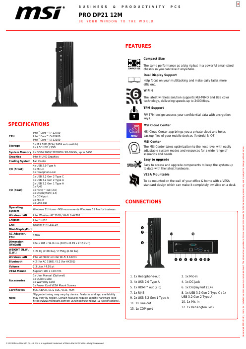
CONNECTIONS
1. 1x Headphone-out 3. 4x USB 2.0 Type A 5. 1x HDMI™ out (2.0) 7. 1x RJ45 9. 2x USB 3.2 Gen 1 Type A 11. 1x Line-out 13. 1x COM port
Generated 2023-03-31, check for the latest version /datasheet. The information provided in this document is intended for informational purposes only and is subject to change without notice.
Storage
1x M.2 SSD (PCIe/ SATA auto switch) 2x 2.5" HDD / SSD
System Memory 2x DDR4 2666/ 3200MHz SO-DIMMs, up to 64GB
Graphics
Intel® UHD Graphics
Cooling System Fan Cooler
I/O (Front)
4x USB 2.0 Type A 1x Mic-in 1x Headphone-out
I/O (Rear)
1x USB 3.2 Gen 2 Type C 1x USB 3.2 Gen 2 Type A 2x USB 3.2 Gen 1 Type A 1x RJ45 1x HDMI™ out (2.0) 1x DisplayPort (1.4) 1x COM port 1x Mic-in 1x Line-out
- 1、下载文档前请自行甄别文档内容的完整性,平台不提供额外的编辑、内容补充、找答案等附加服务。
- 2、"仅部分预览"的文档,不可在线预览部分如存在完整性等问题,可反馈申请退款(可完整预览的文档不适用该条件!)。
- 3、如文档侵犯您的权益,请联系客服反馈,我们会尽快为您处理(人工客服工作时间:9:00-18:30)。
高可用性 主动/主动 - L3模式 主动/被动 – 透明& L3模式 防火墙和VPN会话同步 会话失效转移,路由变化 设备故障检测 链路故障检测 尺寸 外壳:2RU 标准(W x D x H):17.24 x 22.13 x 3.46英寸 公制(W x D x H):438 x 562 x 88毫米 重量:23.4千克(51.6磅) 电源要求 AC输入电压:100 - 240V 频率:47-63 Hz 最高电源:300 W 最高功耗:132 W 最高热输出:450.4 BTU 工作环境条件 温度:32° - 104°F / 0° - 40°C 湿度:20% - 90%(无冷凝) 存储条件 温度:-4° - 158°F / -20° - 70°C 湿度:5% - 95% @ 60°C(无冷凝) 认证 安全: UL, cUL, CB 排放: CE, FCC, TUV, VCCI, C-Tick 环境: RoHS
| Classi cation: [Protected] - All rights reserved 2
Check Point 12400设备
技术规格
基本配置 2个板载1GbE铜接口 8x1GbE铜接口卡(用于3个扩展槽其中之一) 4 GB内存 冗余双热插拔电源 500 GB硬盘驱动器 标准轨道 网络扩展槽选项 4 x 10/100/1000Base-T RJ45 端口 8 x 10/100/1000Base-T RJ45 端口 2 x 1000Base-F SFP 端口 1 4 x 1000Base-F SFP 端口
网关软件刀片
防火墙 IPsec VPN 移动接入 (5个用户) 高级联网 和集群 身份识别 IPS 应用控制 数据丢失防护 URL 过滤 反病毒和 反恶意软件 反垃圾邮件 *备选
12407 12408 12410
■
■
■
■
■
■
■
■
■
■
■
■
■
■
■
■
■
■
■
■
■
*
■
*
*
*
■
*
*
■
*
*
■
©2011 C heck Point S oftware Technologies Ltd. All rights reserved.
2 x 10GBase-F SFP+ 端口
4 x 10GBase-F SFP+ 端口
最高配置J45端口
高达12 x 1000Base-F SFP端口
高达12 x 10GBase-F SFP+端口
12 GB内存
2 x 500 GB HDD RAID-1
SecurityPower是一种测量设备执行多种高级安全功能(软件 刀片)的能力和性能的新基准,如实际流量环境中的IPS、DLP 和应用控制。这提供了一种更好地预测受到安全攻击设备和日 常操作设备的当前和未来行为的有效衡量标准。利用Check Point设备选择工具确定的客户SecurityPower单元(SPU)需 求可与Check Point设备的SPU评级相匹配,从而为具体需求选 择正确的设备。
业务连续性、可靠性和可扩展性
Check Point 12400设备通过热插拔冗余电源、热插拔冗余硬盘 驱动器(RAID)和带外管理高级LOM卡等特点提供业务连续性 和可用性。这些特点组合在一起,可保证当这些设备部署在客户 网络中时实现较高程度的业务连续性和可用性。
SECURITYPOWER ™ 到目前为止,安全设备是根据每种安全功能的具体性能衡量指 标(通常在最佳实验室测试条件下)以及具有一条规则的安全 策略而选择的。如今,客户可通过其SecurityPowerTM评级来 选择安全设备,该评级是基于实际客户流量、多种安全功能以 及典型安全策略。
Check Point 12400设备
12400 实现快速网络性能的数据中心级 安全设备(1046 SPU/25Gbps)
Check Point 12400 设备
目前,企业网关不仅是防火墙。它是为应对日益增多的复杂威胁而提供的一款安 全设备。作为企业安全网关,它必须使用多种技术来控制网络访问,检测复杂攻 击,并提供其它安全能力,如数据丢失防护和防御基于Web的威胁等。智能手机 和平板电脑等移动设备的扩散以及新型流媒体、社交网络和P2P应用软件要求扩 大连接容量和采用新的应用控制技术。最后,向企业私有云和公共云服务的转型 从各个方面改变了公司的边界,要求扩大容量和提供其它安全解决方案。
1 2012第一季度上市 2 SecurityPower: 根据部署软件刀片的实际流量测量设备性能的衡量标准。为你 的性能和安全需求找到正确的设备。
3 软件升级2012年可用
©2011 C heck Point S oftware Technologies Ltd. All rights reserved.
| Classi cation: [Protected] - All rights reserved 3
Check Point 12400设备
软件刀片包规格
基本包 7个安全软件刀片的12400设备(包括防火墙、VPN、高级联网和集群、身份意识、5个并发用户移动接入以及IPS和 应用控制软件刀片),与本地管理捆绑,可用于两个网关
LOM 卡
性能
1046 SecurityPower 2
25 Gbps防火墙吞吐量,1518字节UDP
12 Gbps IPS吞吐量,默认IPS配置文件
350万并发连接数
3
110,000连接数/秒
网络连接
1024 VLANs
256 VLANs 接口
802.3ad被动和主动链路聚合
2层(透明)和3层(路由)模式
软件刀片包 1年期可扩展Check Point软件刀片包,用于12400设备(包括IPS、URL过滤、应用控制、反恶意软件和电子邮件安 全软件刀片、DLP刀片) 1年期Check Point UTM+软件刀片包,用于12400设备(包括IPS、URL过滤、应用控制、反恶意软件和电子邮件安 全软件刀片) 1年期Check Point DLP+软件刀片包,用于12400设备(包括IPS、应用控制和DLP) 1年期Check Point扩展威胁防护软件刀片包,用于12400设备 (包括应用控制和IPS软件刀片) 1年期Check Point网络控制软件刀片包,用于12400设备 (包括应用控制和URL过滤软件刀片) 附加软件刀片 Check Point移动接入软件刀片,无限并发连接数 1年期数据丢失防护软件刀片 (1500个以上用户、250,000邮件/小时、最高吞吐量2.5 Gbps) 1年期Check Point IPS软件刀片 1年期Check Point应用控制软件刀片 1年期Check Point URL过滤软件刀片 1年期Check Point反病毒和反恶意软件刀片 1年期Check Point反垃圾邮件和电子邮件安全软件刀片
远程平台管理和监控 远程管理选项(或LOM)可提供带外远程管理,以从远程位 置对设备进行远程诊断、启动、重启和管理。管理员还可利 用LOM网络界面从ISO文件远程安装OS镜像。
©2011 C heck Point S oftware Technologies Ltd. All rights reserved.
主要特点
■ 1046 SecurityPower™ ■ 25 Gbps 防火墙吞吐量 ■ 12 Gbps IPS吞吐量 ■ 多达26个端口的高端口密度 ■ 双冗余热插拔电源 ■ 备选NICs、HDD和LOM
主要优点
■ 为多软件刀片性能而优化的数据 中心级设备
■ 综合安全设备 ■ 通过一个集成管理控制台简化管理 ■ 可扩展软件刀片架构 ■ 保证远程访问以及站点对站点通信
Check Point的新型设备将快速网络处理技术与高性能多核能力结合在一起,提 供最高层次的安全性,同时不会降低网络速度,保证你的数据、网络和员工安全。 每种设备针对软件刀片架构而优化,能够运行任意软件刀片组合,通过将多种安 全技术合并成一种集成解决方案而为每个网络站点的任意业务提供灵活性和准确 的安全等级。
8个安全刀片的12400设备(包括防火墙、VPN、高级联网和集群、身份意识、5个并发用户移动接入以及IPS、应用 控制和DLP刀片);与本地管理捆绑,可用于两个网关
10个安全软件刀片的12400设备(包括防火墙、VPN、高级联网和集群、身份意识、5个并发用户移动接入以及IPS、 应用控制、URL过滤、反恶意软件和电子邮件安全软件刀片);与本地管理捆绑,可用于两个网关
概述 鉴于高安全软件刀片性能和高度可升级性,12400设备是一种数据中心级平台,提 供高级冗余和模块化。除了两个板载1 GB铜以太网端口,三个可用扩展槽,可用于 配置各种网络选项,如1 GB以太网铜、1 GB以太网光纤和10 GB以太网光纤连接。
12400默认配置包括一块有八个1 GB以太网铜端口的扩展卡。完全加载后,12400 支持多达26个1 GB以太网端口或12个10 GB以太网端口。
(选装) 9 三个网卡扩展槽
(默认一个8 x 10/100/1000Base-T端口卡) 10 4GB RAM升级(选装)1 11 两个冗余热插拔AC电源 12 伸缩轨道(选装)
1
2 3 4 56
78
9
10
11 12
12400包含热插拔电源和选装的热插拔冗余磁盘驱动器。远程 管理选项也可用。
12400提供1046个SecurityPower单元,防火墙吞吐量25 Gbps, IPS吞吐量12 Gbps,具有比同类产品卓越的性能,所有这些均 集成在一个双机架单元(2RU)的特定目的安全设备内。
| Classi cation: [Protected] - All rights reserved 1
