力士乐泵资料PPT课件
力士乐A4VSO__PPT文档

1. 球面配油盘 斜盘泵的原理决定,缸体有倾覆力矩。它造成配油盘和 缸体的不良接触,不仅使性能降低而且影响可靠性。 球面配油是理想的解决方案,这是力士乐专利。
2. 锻造增强型滑靴 3. 回程盘和缸体氮化处理
4. 带有内花键的球面弹簧保持器
AA44VVSS 油油泵泵的的优优点点
锻造增强性 滑靴
AA44VVSS 油油泵泵的的优优点点
变量指示器 新密封结构
AA44VVSS 油油泵泵的的优优点点
陶瓷环允许 使用高绍尔 硬度的主轴
密封
提高密封可靠 性和密封寿命
AA44VVSS 油油泵泵的的优优点点
满足高水基难燃介质的使用要求
1 主轴密封 2 外部冲洗 3 内部冲洗 4 带有保持器的轴承 5 专利配油盘 6 配油盘机械固定
恒功率控制 LR
i
EP 电控变量
二次调节 DS1
q
α
压力指令控制 DRG
± q 控制控制 A10V-DFE1 A4VSO E1 - S02
AA44VVSS 油油泵泵的的优优点点
规格范围
工作油温: - 25度 - +90度 粘度范围:10 mm2 / S - 1000 mm2 / S 通轴连接: 100% 排量范围: 40, 71, 125, 180, 250, 355,
AA44VVSS 油油泵泵的的优优点点
力士乐油泵简介A11V(L)O
朋友们大家早上好
A11VO 2177-e / 08.99
Βιβλιοθήκη Baidu
认识A11V(L)O
各种控制块 泵头阀
通轴驱动 吸油离心泵 可选的泵摆角指示器
Size Speed A11VO A11VLO
3000 40 60 75 95 130 190 260 130 3000 2700 2550 2350 2100 190 260
点动电机,检查旋向。确认无误后,空转运行3-5分钟后,期间注意排
气。缓慢反复动作各执行元件,使执行元件充满油液。期间如果有可以排 气的机构,注意排气。
试车过程中随时检查液位,不足则用滤油机加油。观察油液是否含有气
泡,如果有,需静置待气泡消除后再进行下一步试车工作。否则,气体 进入泵中,会造成气蚀现象。
吸油管的安装
A11VO 2161-e / VAV 08.99
油泵的常见故障现象及原因(吸油软管的安装)
吸油管的安装
A11VO 2161-e / VAV 08.99
油泵的常见故障现象及原因(针对A11VOLRDS、A11VODRS泵) 5、噪音、发热、泵损坏问题。
当发现油泵异常发热时,油泵发热部位在前轴承处,一般意味着轴 承损坏;一般来说,油泵壳体的温度比油箱温度高10-15度是正常 的,如果温度过高,就要考虑是不是油泵泄漏量太大;此时需要检 查一下油泵出口过滤器以及系统回油过滤器,如果发现滤芯中有铜 屑,基本上说明泵已经异常磨损了;再进一步检查油泵的外泄漏量 ,即测量油泵T口泄漏量,注意是在工作压力下(例如200bar)检 测才有意义。(油泵的泄漏可以划分为内泄露和外泄漏,内泄露是 指配油盘和缸体之间从压油区向吸油区的泄漏量,我们无法测量;外 泄漏是指油泵中各摩擦幅向油泵壳体中泄漏的油,这是我们关注的 )一般的来说我们认为泄漏量在泵额定流量10%以内,是可以接受 的,超出10%泵应该进行维修。
博世力士乐液压
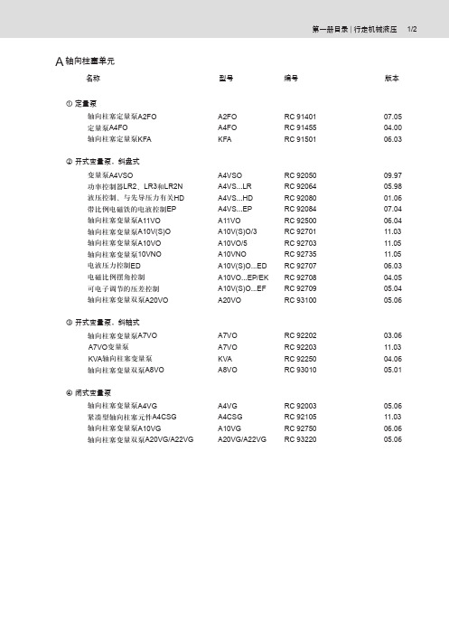
A 轴向柱塞单元
名称 型号 编号 版本
① 定量泵
轴向柱塞定量泵A2FO 定量泵A4FO 轴向柱塞定量泵KFA ② 开式变量泵,斜盘式 变量泵A4VSO
功率控制器LR2、LR3和LR2N 液压控制、与先导压力有关HD 带比例电磁铁的电液控制EP
轴向柱塞变量泵A11VO 轴向柱塞变量泵A10V(S)O 轴向柱塞变量泵A10VO 轴向柱塞变量泵10VNO 电液压力控制ED 电磁比例摆角控制 可电子调节的压差控制 轴向柱塞变量双泵A20VO ③ 开式变量泵,斜轴式 轴向柱塞变量泵A7VO A7VO 变量泵 KVA 轴向柱塞变量泵 轴向柱塞变量双泵A8VO ④ 闭式变量泵
轴向柱塞变量泵A4VG 紧凑型轴向柱塞元件A4CSG 轴向柱塞变量泵A10VG
轴向柱塞变量双泵A20VG/A22VG
第一册目录 | 行走机械液压 1/2
A2FO A4FO KFA
A4VSO A4VS...LR A4VS...HD A4VS...EP A11VO A10V(S)O/3A10VO/5A10VNO A10V(S)O...ED A10VO...EP/EK A10V(S)O...EF A20VO
A7VO A7VO KVA A8VO
A4VG A4CSG A10VG A20VG/A22VG
07.0504.0006.03
09.9705.9801.0607.0406.0411.0311.0511.0506.0304.0505.0405.06
03.0611.0304.0605.01
05.0611.0306.0605.06
RC 91401RC 91455RC 91501
力士乐泵资料
A10 146.15.e/VST6/H 01.AK
A10V(S)O pressure, flow and power control DFLR
Ports
Powercontrol LR
Pressure port B Case drain port L
Pressure control DR
Standard setting:
Attention:
The mini - measurement connection have to be shortened according to the original lenght of the plug (reach of a screw 7 mm).
Measurement high pressure:
At this particular spot, the existing plugs (M8 x 1) can be replaced by mini measurement connections
A10V(S)O Pressure/Flow control DFR(1) Adjustment for pressure- res. flow control
220
210
Dp = 15 bar
200
190
180
170
160
150
140
力士乐泵资料ppt课件
Slit in longitudinal direction: orifice opened
Slit in cross direction
: orifice closed, SO 74)
A10V(S)O Pressure/Flow control DFR(1) Measurement of high pressure
A10 - series 52: DFR(1) - with return line orifice
(Standard: 2,2 mm !)
X
FR
DRቤተ መጻሕፍቲ ባይዱ
Special design (Stabilization): SO 116: Return line orifice 1,3 mm SO 229: Return line orifice 1,5 mm SO 231: Return line orifice 2,2 mm SO 277: Return line orifice 1,0 mm SO 381: Return line orifice 0,8 mm SO 617: Return line orifice 0,6 mm
Suction port S
A10V(S)O pressure, flow and power control DFLR Circuit diagram
A10V(S)O pressure, flow and power control DFLR Function and circuit diagram
力士乐A11V油泵讲解PPT文档40页
56、死去何所道,托体同山阿。 57、春秋多佳日,登高赋新诗。 58、种豆南山下,草盛豆苗稀。晨兴 理荒秽 ,带月 荷锄归 。道狭 草木长 ,夕露 沾我衣 。衣沾 不足惜 ,但使 愿无违 。 59、相见无杂言,但道桑麻长。 60、迢迢新秋夕,亭亭月将圆。
谢谢!
36、自己的鞋子,自己知道紧在哪里。——西班牙
37、我们唯一不会改正的缺点是软弱。——拉罗什福科
xiexie! 38、我这个人走得很慢,但是我从不后退。——亚伯拉罕·林肯
39、勿问成功的秘诀为何,且尽全力做你应该做的事吧。——美华纳
40、学而不思则罔,思而不学则殆。——孔子
Biblioteka Baidu
德国力士乐油泵
十
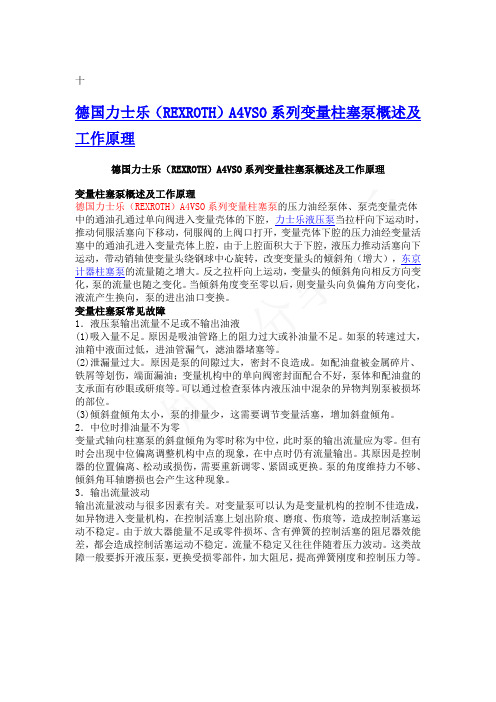
德国力士乐(REXROTH)A4VSO系列变量柱塞泵概述及工作原理
德国力士乐(REXROTH)A4VSO系列变量柱塞泵概述及工作原理
变量柱塞泵概述及工作原理
德国力士乐(REXROTH)A4VSO系列变量柱塞泵的压力油经泵体、泵壳变量壳体中的通油孔通过单向阀进入变量壳体的下腔,力士乐液压泵当拉杆向下运动时,推动伺服活塞向下移动,伺服阀的上阀口打开,变量壳体下腔的压力油经变量活塞中的通油孔进入变量壳体上腔,由于上腔面积大于下腔,液压力推动活塞向下运动,带动销轴使变量头绕钢球中心旋转,改变变量头的倾斜角(增大),东京计器柱塞泵的流量随之增大。反之拉杆向上运动,变量头的倾斜角向相反方向变化,泵的流量也随之变化。当倾斜角度变至零以后,则变量头向负偏角方向变化,液流产生换向,泵的进出油口变换。
变量柱塞泵常见故障
1.液压泵输出流量不足或不输出油液
(1)吸入量不足。原因是吸油管路上的阻力过大或补油量不足。如泵的转速过大,油箱中液面过低,进油管漏气,滤油器堵塞等。
(2)泄漏量过大。原因是泵的间隙过大,密封不良造成。如配油盘被金属碎片、铁屑等划伤,端面漏油;变量机构中的单向阀密封面配合不好,泵体和配油盘的支承面有砂眼或研痕等。可以通过检查泵体内液压油中混杂的异物判别泵被损坏的部位。
(3)倾斜盘倾角太小,泵的排量少,这需要调节变量活塞,增加斜盘倾角。2.中位时排油量不为零
变量式轴向柱塞泵的斜盘倾角为零时称为中位,此时泵的输出流量应为零。但有时会出现中位偏离调整机构中点的现象,在中点时仍有流量输出。其原因是控制器的位置偏离、松动或损伤,需要重新调零、紧固或更换。泵的角度维持力不够、倾斜角耳轴磨损也会产生这种现象。
力士乐泵(A4VSO)
P Z
= available = in preparation – = not available = preferred programme (with short delivery times) (for preferred types see page 39)
2/40
Brueninghaus Hydromatik
Brueninghaus Hydromatik 1
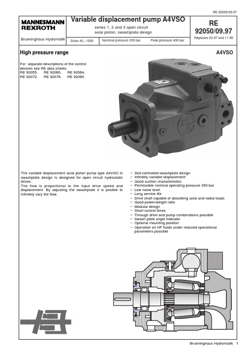
RE 92050/09.97 92050/03.97 Variable displacement pump A4VSO, series 1, 2 and 3
Ordering details
Hydraulic fluid / version Mineral oil (no code) HF hydraulic fluid (with the exception of Skydrol) High-Speed-Version Axial piston unit Swashplate design, variable, for industrial applications Boost pump (Impeller) Without boost pump (no code) With boost pump (Impeller) only for version 25 Type of operation Pump, open circuit Nominal size displacement Vg max (cm 3) Control device Pressure control Flow control Power control with hyperbolic curve Manual control Electric motor control Hydraulic control, position dependent Hydraulic control, volume dependent DR FR LR MA EM HW HM – – – – – – – DR.. FR.. LR.. MA.. EM.. HW.. HM.. HS.. EO.. HD.. DS.. 40 71 125 180 250 355 500 750 1000 O 40 – 71 – 125 180 250 355 500 750 1000 – – – – – – L A4VS 40 71 125 180 250 355 500 750 1000 – – – – E H
力士乐液压培训资料ppt课件

Flushing valve Flushing pressure valve
可内置冲洗阀
Flushing valve Flushing pressure valve
2020年A46月V 211759-日e / V星AV期08.三99
13
–☺ 闭式回路系统的优点:
–油泵较小:因为闭式系统中使用的油泵可以比 开式系统中使用的
油泵的转速高很多(特别适合发动 机驱动的系统).
–没有控制阀,由油泵确定流量和流向.
–没有制动阀,负载通过油泵作用在发动机上 (负功率).
–油箱小,只须给主回路补油(约为最大流量 的25%).
–冷却器小,负载下降时的能量不全部转变为
热. 2020年4月15日星期三
14
• 典型结构形式:
MCR控制原理
广西柳工股份机械有限公司
2020年4月15日星期三
1
2020年4月15日星期三
2
其它注意源自文库项
安装位置:任意,但工作过程中及停车时泵壳内应充满油液。 轴封的工作温度 -450C。。。-250C 要求用NBR
-250C。。。+900C 标准用轴封NBR, 也可用FPM +900C。。。+1150C 要求用FPM
变矩范围
多为定量马达,所以变量范围较小
可利用变量马达,和改变减速机 的传动比来获得大的变矩范围
(完整版)Rexroth力士乐柱塞泵工作原理与说明
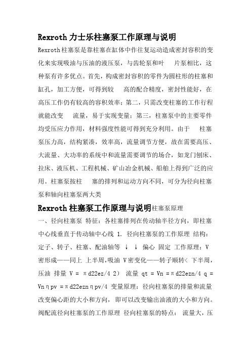
Rexroth力士乐柱塞泵工作原理与说明
Rexroth柱塞泵是靠柱塞在缸体中作往复运动造成密封容积的变化来实现吸油与压油的液压泵,与齿轮泵和叶片泵相比,这种泵有许多优点。首先,构成密封容积的零件为圆柱形的柱塞和缸孔,加工方便,可得到较高的配合精度,密封性能好,在高压工作仍有较高的容积效率;第二,只需改变柱塞的工作行程就能改变流量,易于实现变量;第三,柱塞泵中的主要零件均受压应力作用,材料强度性能可得到充分利用。由于柱塞泵压力高,结构紧凑,效率高,流量调节方便,故在需要高压、大流量、大功率的系统中和流量需要调节的场合,如龙门刨床、拉床、液压机、工程机械、矿山冶金机械、船舶上得到广泛的应用。柱塞泵按柱塞的排列和运动方向不同,可分为径向柱塞泵和轴向柱塞泵两大类
Rexroth柱塞泵工作原理与说明柱塞泵原理
一、径向柱塞泵特征:各柱塞排列在传动轴半径方向,即柱塞中心线垂直于传动轴中心线 1. 径向柱塞泵的工作原理结构:定子、转子、柱塞、配油轴等↓ ↓ 偏心固定工作原理:V
密形成——同上上半周,吸油 V密变化——转子顺转< 下半周,压油排量V = πd22ez/4 2)流量 qt = Vn =πd22ezn/4 q = Vnηpv =πd22eznηpv/4 变量原理:径向柱塞泵的排量和流量改变偏心距的大小和方向,即可以改变输出油液的大小和方向。阀配流径向柱塞泵的工作原理径向柱塞泵的特点:流量大,压
力高,便于作成多排柱塞的形式,工作可靠但径向尺寸大,自吸能力差,配流轴径向力不平衡,易磨损,间隙不能补偿,故限制了转速和压力的提高。1.轴向柱塞泵的工作原理轴向柱塞泵是将多个柱塞配置在一个共同缸体的圆周上,并使柱塞中心线和缸体中心线平行的一种泵。轴向柱塞泵有两种形式,直轴式(斜盘式)和斜轴式(摆缸式),
力士乐A8VO变量泵(个人苦心详解版)
28
-内置辅助泵,带溢流阀,可带减压阀
32
-驱动输出可安装轴向柱塞和齿轮泵
34
-功率重量比高
35
-使用寿命长
37
40
/40 博世力士乐
A8VO│RC 93 010/06.06
订货型号/标准产品
A8V O
/
01
02
03
04
R1
05
06
07
–NZ
05
08
09
10
11
12
13
14
轴向柱塞元件 01 变量,斜轴结构
重量约
m
kg
55 2 x 54,8 0 1,0 2500 3000 2 x 137 160 611 0,017 82
80 2 x 80 0 1,0 2240 2750 2 x 179 209 891 0,022 90
107 2 x 10⁷ 0 1,0 2150 2450 2 x 230 268 1192 0,035 116
粘度n in mm2/s
选择图
-40° 1600
-20°
0°
20° 40° 60° 80° 100° 1600
1000
600
400
100 VG 68 VG 46 VG 32 VG 22 VG
200
100
- 1、下载文档前请自行甄别文档内容的完整性,平台不提供额外的编辑、内容补充、找答案等附加服务。
- 2、"仅部分预览"的文档,不可在线预览部分如存在完整性等问题,可反馈申请退款(可完整预览的文档不适用该条件!)。
- 3、如文档侵犯您的权益,请联系客服反馈,我们会尽快为您处理(人工客服工作时间:9:00-18:30)。
Measuring - point 1: High pressure (measurable at plug of DR valve axis)
Adjustment DR : each rotation app. 50 bar !
- 50 bar + 50 bar
Attention:
The mini - measurement connection have to be shortened according to the original lenght of the plug (reach of a screw 7 mm).
Measurement high pressure:
Slit in longitudinal direction: orifice opened
Slit in cross direction
: orifice closed, SO 74)
A10V(S)O Pressure/Flow control DFR(1) Measurement of high pressure
Adjustment of pressure control
Adjustment of flow control:
„Stand - by“ pressure measurement
or
ห้องสมุดไป่ตู้
Differential pressure measurement with swivel angle !
Valve axis: Pressure control
pHD
X DFR1
n = 1500 rpm Dp = 15 bar Stand by = 20 bar
px
100
125
F鰎dermenge in l/min
A10V(S)O Pressure/Flow control DFR(1) Decompression orifice and damping orifice
b
220 210 200 190 180 170 160 150 140 130 120 110 100 90 80 70 60 50 40 30 20 10
0
A 10 VO 7H4igh pressure: p HD
Delta p - Verhalten
Grundeinstellung Standby = 20bar
Valve axis: Flow control
A10V(S)O Pressure/Flow control DFR(1) Adjustment of pressure control DR
Procedure: FR - flow control blocked ! High pressure line closed ! Adjusting of DR pressure control
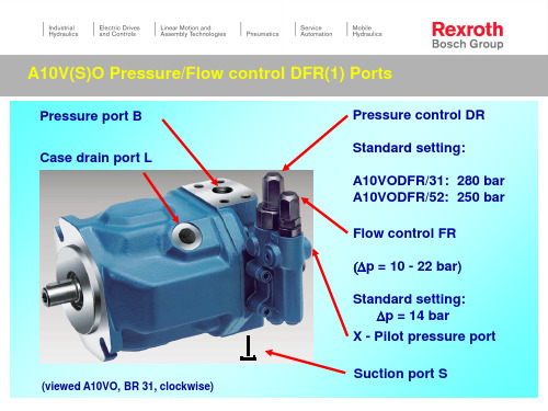
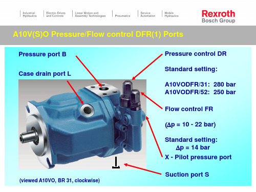
A10V(S)O Pressure/Flow control DFR(1) Ports
Pressure port B Case drain port L
(viewed A10VO, BR 31, clockwise)
Pressure control DR
Standard setting:
A10VODFR/31: 280 bar A10VODFR/52: 250 bar
DFR with decompression orifice:
(DFR: Standard: 0,35 mm) (DFR1: closed, without drilling)
X
FR
FR - axis
DR
DR - axis
Damping orifice DR - FR
(Standard: 0,6 mm,
220 210 200 190 180 170 160 150 140 130 120 110 100 90 80 70 60 50 40 30 20 10
0 0
Dp = 15 bar
25
50
75
Simulated load pressure: p X
A10 VO 74 DFR(1)
Mode of experimental procedure:
At this particular spot, the existing plugs (M8 x 1) can be replaced by mini measurement connections
A10V(S)O Pressure/Flow control DFR(1) Adjustment for pressure- res. flow control
Orifice res. Mobile LS - pilot pressure valve block
DR - axis FR - axis
X
X
FR DR
A10V(S)O Pressure/Flow control DFR(1) Dp - control characteristic f (x) = (px, Vg)
Flow control FR
(Dp = 10 - 22 bar)
Standard setting: Dp = 14 bar
X - Pilot pressure port
Suction port S
A10V(S)O Pressure/Flow control DFR(1) Circuit diagram
Adjustable orifice, res. Mobile valve block (not included in supply)
FR
DR
X - port Flow control (Standard: Dp = 14 bar);
Decompression orifice
Pressure port
Damping orifice
Control piston
(Circuit diagram
viewed for A10VO,
series 31)
Counter balance piston and mechanical spring
A10V(S)O Pressure/Flow control DFR(1) Function and circuit diagram