TPS77518PWP中文资料
友台半导体有限公司产品说明书-75XX-1系列高压稳压器

■ 产品简介75XX-1系列是采用CMOS 工艺制造,低功耗的高压稳压器,最高输入电压可达30V ,输出电压范围为1.5V ~12.0V 。
它具有高精度的输出电压、极低的供电电流、极低的跌落电压等特点。
■ 产品特点■ 产品用途■ 封装形式和管脚功能定义■ 型号选择名称型号 最高输入电压(V)输出电压(V)容差 封装形式7530-1 30 3.0 +3%TO 92 SOT89-37533-130 3.3 +3% 7536-1 30 3.6 +3% 7544-1 30 4.4 +3% 7550-1305.0+3%● 低功耗:≤3μA● 低跌落电压:典型值0.1V ● 低温漂:典型值50 ppm/℃ ● 高的输入电压:最高可达30V● 高精度的输出电压:容差为+3%● 封装形式:TO-92、SOT89-3 ● 电池等电源的供电设备● 各种通信设备 ● 音频/视频设备 ● 安防监控设备75XX-1LDO 高压稳压器、SOT-23-3SOT-23-3SOT-23-3管脚序号管脚定义功能说明TO-92SOT89-3SOT23-3111GND 芯片接地端223VIN 启动输入端332VOUT 芯片输出端■ 原理框图■ 极限参数项目 符号 参数 极限值 单位 电压 VIN 最大输入电压30 V 功耗PD 功耗 400 mW 温度Tw工作温度 -25~70 ℃ Tc 存储温度 -50~125 ℃ Th焊接温度260℃,10s■ 电学特性7530-1 ( T OPT=25℃)符号参数 测试条件 最小值 典型值 最大值 单位 V OUT 输出电压 V IN =5V ,I OUT =10mA2.91 33.09V I OUT 输出电流 V IN =5V60 100mA △V OUT 负载调节 V IN =5V ,1mA ≤I OUT ≤20mA- 100 150 mV V DIF 跌落电压 I OUT =1mA - 100 - mV I SS 静态电流 V IN =5V ,空载 - 2 3 µA ΔV OUT /(ΔV IN * V OUT ) Line Regulation4V ≤V IN ≤30V ,I OUT =1mA- 0.2 - %/V V IN 输入电压 -- - 30 V ΔV OUT /ΔTa温度系数V IN =5V ,I OUT =10mA 0℃≤Ta ≤70℃-+0.45-mV/℃V ref V in GN DV outLDO 高压稳压器7533-1 (TOPT=25℃)符号参数测试条件最小值典型值最大值单位V OUT输出电压V IN=5.5V,I OUT=10mA 3.201 3.3 3.399 VI OUT输出电流V IN=5.5V 60 100-mA△V OUT负载调节V IN=5.5V,1mA≤I OUT≤30mA -100150 mV V DIF跌落电压I OUT=1mA -100 -mVI SS静态电流V IN=5.5V,空载- 2 3 µA ΔV OUT/(ΔV IN* V OUT) Line Regulation 4.5V≤V IN≤30V,I OUT=1mA -0.2 -%/V V IN输入电压---30 VΔV OUT /ΔTa 温度系数V IN=5.5V,I OUT=10mA,0℃≤Ta≤70℃-+0.5 -mV/℃7536-1 (TOPT=25℃) 符号参数测试条件最小值典型值最大值单位V OUT输出电压V IN=5.6V,I OUT=10mA 3.492 3.6 3.708 VI OUT输出电流V IN=5.6V 60 100-mA△V OUT负载调节V IN=5.6V,1mA≤I OUT≤30mA -100150 mV V DIF跌落电压I OUT=1mA -100-mVI SS静态电流V IN=5.6V,空载- 2 3 µA ΔV OUT/(ΔV IN* V OUT) Line Regulation 4.6V≤V IN≤30V,I OUT=1mA -0.2 -%/V V IN输入电压---30 VΔV OUT /ΔTa 温度系数V IN=5.6V,I OUT=10mA,0℃≤Ta≤70℃-+0.6 -mV/℃7544-1 (TOPT=25℃)符号参数测试条件最小值典型值最大值单位V OUT输出电压V IN=6.4V,I OUT=10mA 4.268 4.4 4.532 VI OUT输出电流V IN=6.4V 60 100-mA△V OUT负载调节V IN=6.4V,1mA≤I OUT≤30mA -100150 mV V DIF跌落电压I OUT=1mA -100 -mVI SS静态电流V IN=6.4V,空载- 2 3 µA ΔV OUT/(ΔV IN* V OUT) Line Regulation 5.4V≤V IN≤30V,I OUT=1mA -0.2 -%/V V IN输入电压---30 VΔV OUT /ΔTa 温度系数V IN=6.4V,I OUT=10mA,0℃≤Ta≤70℃-+0.7 -mV/℃7550-1 (TOPT=25℃)符号参数测试条件最小值典型值最大值单位V OUT输出电压V IN=7V,I OUT=10mA 4.85 5 5.15 VI OUT输出电流V IN=7V 60 100-mA△V OUT负载调节V IN=7V,1mA≤I OUT≤30mA -100mV V DIF跌落电压I OUT=1mA -100 -mVI SS静态电流V IN=7V,空载- 2 3 µA ΔV OUT/(ΔV IN* V OUT) Line Regulation 6V≤V IN≤30V,I OUT=1mA -0.2 -%/V V IN输入电压---30 VΔV OUT /ΔTa 温度系数V IN=7V,I OUT=10mA,0℃≤Ta≤70℃-+0.75 -mV/℃■应用电路1、基本电路2、高输出电流稳压电路1 3275X X-1V IN V ou tG N DC210uF C110uFV in V out75XX-13、短路保护电路75XX-14、提高输出电压电路(1)75XX-1V OUT=Vxx(1+R2/R1)+Iss*R2 5、提高输出电压电路(2)75XX-1V OUT=Vxx+VD16、电流调节电路75XX-1IOUT = VXX/RX + ISS 7、双端输出电路75XX-175XX-1注示:“××”代表输出电压■ 封装信息LDO 高压稳压器LDO高压稳压器SOT-23-3LDO高压稳压器UMW R UMW 75XX。
中文ade7758

ADE7758芯片简单手册摘要:本文介绍基于ADE7758 和PIC系列MCU的多相多功能电能测量电表,本文重点介绍ADE7758的引脚及设计要点、内部寄存器功能和工作原理,以及ADE7758与PIC16F877的中断接口时序。
关键词:多相电能表;ADE7758;PIC0引言我国与发达国家一样,随着电力供应市场化的逐步深入和计算机网络的快速普及和发展,为了缓解电力供应紧张的现状,正在大力推广分时电价,双费率电子电能表成为电能表新的发展趋势和需求热点。
仅上海市自2001年起,五年内需要600万台复费率电能表。
国外电能表正在向大电流、大动态的需求方向发展。
美国模拟器件公司开发出一种体积小巧、动态范围可达1000:1的新型电能测量集成电路ADE7758,该IC内嵌了高精度的模数转换器和固定模式的数字处理信号处理器(DSP),具有数字积分、数字滤波和具有众多实用电能监测、计量功能,正成为新一代高性能全数字电能表的理想芯片。
截止到2002年10月, AD775X系列全数字电能测量处理芯片在全世界的销量已超过5000万片。
ADE7758是具有每相信息的多相多功能电能测量IC芯片,是美国ADI公司2003年8月推出的专用电能测量IC新产品。
A D E775X系列电能测量专用集成电路芯片的推出,不仅简化了电力测量新应用模块的设计难度,可做到全电子或真正固体化、静止化,以有利于提高性能,降低成本;还可以利用现有的电话线、专线、高频无线电调制解调器、光缆、低压配电线载波等技术手段完成自动抄读表、分时电价、实时电价、多功能计量、预付费等扩充应用功能。
使电能计量具有高精度、高可靠性、免维护和双向通讯功能,适应电力市场化下的电力公司提供新的增值服务。
ADE7758是一款功能先进的数字电能表芯片,它与单片机PIC16F877 、LCD模块、电源等构成的一种多费率电子电能表电路见图。
ADE7753通过串行接口与单片机通信,接收单片机控制,实现多费率计量。
TPS70445PWP中文资料

description
The TPS704xx family of devices consists of dual-output low-dropout voltage regulators with integrated SVS (RESET, POR, or power on reset) and power good (PG) functions. These devices are capable of supplying 1 A and 2 A by regulator 1 and regulator 2 respectively. Quiescent current is typically 185 µA at full load. Differentiated features, such as accuracy, fast transient response, SVS supervisory circuit (power on reset), manual reset input, and independent enable functions provide a complete system solution.
PRODUCTION DATA information is current as of publication date. Products conform to specifications per the terms of Texas Instruments standard warranty. Production processing does not necessarily include testing of all parameters.
元器件交易网
集成电路IC 稳压器TPS61175PWPR TPS61175PWP

TPS61175 SLVS892B–DECEMBER2008–REVISED FEBRUARY2012 3-A High Voltage Boost Converter with Soft-start and Programmable Switching FrequencyCheck for Samples:TPS61175FEATURES DESCRIPTIONThe TPS61175is a monolithic switching regulator • 2.9-V to18-V Input Voltage Rangewith integrated3-A,40-V power switch.It can be •3A,40V Internal Switch configured in several standard switching-regulator•High Efficiency Power Conversion:Up to93%topologies,including boost,SEPIC and flyback.Thedevice has a wide input voltage range to support •Frequency Set by External Resistor:200-kHzapplication with input voltage from multi-cell batteries to2.2-MHzor regulated5-V,12-V power rails.•Synchronous External Switching FrequencyThe TPS61175regulates the output voltage with •User Defined Soft Start into Full Loadcurrent mode PWM(pulse width modulation)control.•Skip-Switching Cycle for Output Regulation at The switching frequency of PWM is either set by an Light Load external resistor or an external clock signal.The usercan program the switching frequency from200-kHz to •14-pin HTSSOP Package with PowerPad™2.2-MHz.APPLICATIONS The device features a programmable soft-startfunction to limit inrush current during start-up,and •5V to12V,24V power conversionhas built-in other protection features,such as pulse-•Supports SEPIC,Flyback topologyby-pulse over current limit and thermal shutdown.The •ADSL Modems TPS61175is available in14-pin HTSSOP packagewith Powerpad.•TV TunerTYPICAL APPLICATION FOR BOOST CONVERTERFigure1.Typical ApplicationORDERING INFORMATION(1)T A PART NUMBER PACKAGE(2)–40°C to85°C TPS61175PWP HTSSOP-14(1)For the most current package and ordering information,see the TI Web site at .(2)The PWP package is available in tape and reel.Add R suffix(TPS61175PWPR)to order quantities of2000parts per reel.Without suffix,the TPS61175PWP is shipped in tubes with90parts per tube.Please be aware that an important notice concerning availability,standard warranty,and use in critical applications ofTexas Instruments semiconductor products and disclaimers thereto appears at the end of this data sheet.PowerPad is a trademark of Texas Instruments.PRODUCTION DATA information is current as of publication date.Copyright©2008–2012,Texas Instruments Incorporated Products conform to specifications per the terms of the TexasInstruments standard warranty.Production processing does notnecessarily include testing of all parameters.TPS61175SLVS892B–DECEMBER2008–REVISED These devices have limited built-in ESD protection.The leads should be shorted together or the device placed in conductive foam during storage or handling to prevent electrostatic damage to the MOS gates.ABSOLUTE MAXIMUM RATINGS(1)over operating free-air temperature range(unless otherwise noted)VALUE UNIT Supply Voltages on pin VIN(2)–0.3to20V Voltages on pins EN(2)–0.3to20V Voltage on pin FB,FREQ and COMP(2)–0.3to3V Voltage on pin SYNC,SS(2)–0.3to7V Voltage on pin SW(2)–0.3to40V Continuous Power Dissipation See the Thermal Information Table Operating Junction Temperature Range–40to+150°C Storage Temperature Range–65to+150°C (1)Stresses beyond those listed under"absolute maximum ratings"may cause permanent damage to the device.These are stress ratingsonly and functional operation of the device at these or any other conditions beyond those indicated under"recommended operating conditions"is not implied.Exposure to absolute-maximum-rated conditions for extended periods may affect device reliability.(2)All voltage values are with respect to network ground terminal.THERMAL INFORMATIONTPS61175THERMAL METRIC(1)UNITSPWP14PINSθJA Junction-to-ambient thermal resistance45.2θJCtop Junction-to-case(top)thermal resistance34.9θJB Junction-to-board thermal resistance30.1°C/WψJT Junction-to-top characterization parameter 1.5ψJB Junction-to-board characterization parameter29.9θJCbot Junction-to-case(bottom)thermal resistance 5.8(1)For more information about traditional and new thermal metrics,see the IC Package Thermal Metrics application report,SPRA953. RECOMMENDED OPERATING CONDITIONSover operating free-air temperature range(unless otherwise noted)MIN NOM MAX UNITV IN Input voltage range 2.918VV O Output voltage range V IN38VL Inductor(1) 4.747μHf SW Switching frequency2002200kHzC I Input Capacitor 4.7μFC O Output Capacitor 4.7μFV SYN External Switching Frequency Logic5VT A Operating ambient temperature–4085°CT J Operating junction temperature–40125°C (1)The inductance value depends on the switching frequency and end application.While larger values may be used,values between4.7-μH and47-μH have been successfully tested in various applications.Refer to the Inductor Selection for detail.2Submit Documentation Feedback Copyright©2008–2012,Texas Instruments IncorporatedProduct Folder Link(s):TPS61175TPS61175 SLVS892B–DECEMBER2008–REVISED FEBRUARY2012ELECTRICAL CHARACTERISTICSFSW=1.2MHz(Rfreq=80kΩ),Vin=3.6V,T A=–40°C to+85°C,typical values are at T A=25°C(unless otherwise noted) PARAMETER TEST CONDITIONS MIN TYP MAX UNIT SUPPLY CURRENTV IN Input voltage range 2.918VI Q Operating quiescent current into Vin Device PWM switching without load 3.5mAI SD Shutdown current EN=GND 1.5μAV UVLO Under-voltage lockout threshold 2.5 2.7VV hys Under-voltage lockout hysteresis130mV ENABLE AND REFERENCE CONTROLV enh EN logic high voltage Vin=2.9V to18V 1.2VV enl EN logic low voltage Vin=2.9V to18V0.4VV SYNh SYN logic high voltage 1.2V SYNl SYN logic low voltage0.4VR en EN pull down resistor4008001600kΩT off Shutdown delay,SS discharge EN high to low10ms VOLTAGE AND CURRENT CONTROLV REF Voltage feedback regulation voltage 1.204 1.229 1.254VI FB Voltage feedback input bias current200nAI sink Comp pin sink current V FB=V REF+200mV,V COMP=1V50μAI source Comp pin source current V FB=V REF–200mV,V COMP=1V130μAV CCLP Comp pin Clamp Voltage High Clamp,V FB=1V3VLow Clamp,V FB=1.5V0.75V CTH Comp pin threshold Duty cycle=0%0.95VG ea Error amplifier transconductance240340440μmhoR ea Error amplifier output resistance10MΩf ea Error amplifier crossover frequency500KHz FREQUENCYRfreq=480kΩ0.160.210.26f S Oscillator frequency Rfreq=80kΩ 1.0 1.2 1.4MHzRfreq=40kΩ 1.76 2.2 2.64D max Maximum duty cycle V FB=1.0V,Rfreq=80kΩ89%93%V FREQ FREQ pin voltage 1.229VT min_on Minimum on pulse width Rfreq=80kΩ60ns POWER SWITCHR DS(ON)N-channel MOSFET on-resistance V IN=V GS=3.6V0.130.25ΩV IN=V GS=3.0V0.130.3I LN_NFET N-channel leakage current V DS=40V,T A=25°C1μA OC,OVP AND SSI LIM N-Channel MOSFET current limit D=D max3 3.85AI SS Soft start bias current Vss=0V6μA THERMAL SHUTDOWNT shutdown Thermal shutdown threshold160°CT hysteresis Thermal shutdown threshold hysteresis15°CCopyright©2008–2012,Texas Instruments Incorporated Submit Documentation Feedback3Product Folder Link(s):TPS61175TSSOP 14-pin TPS61175SLVS892B –DECEMBER 2008–REVISED FEBRUARY 2012DEVICE INFORMATIONPIN ASSIGNMENTSPIN FUNCTIONSPINDESCRIPTIONI/O NAME NO.VIN3IThe input supply pin for the IC.Connect VIN to a supply voltage between 2.9V and 18V.It is acceptable for the voltage on the pin to be different from the boost power stage input for applications requiring voltage beyond VIN range.SW 1,2I This is the switching node of the IC.Connect SW to the switched side of the inductor.FB 9I Feedback pin for positive voltage regulation.Connect to the center tap of a resistor divider to program the output voltage.EN 4I Enable pin.When the voltage of this pin falls below the enable threshold for more than 10ms,the IC turns off.COMP 8O Output of the internal transconductance error amplifier.An external RC network is connected to this pin to compensate the regulator.SS 5O Soft start programming pin.A capacitor between the SS pin and GND pin programs soft start timing.See application section for information on how to size the SS capacitor.FREQ 10O Switch frequency program pin.An external resistor is connected to this pin to set switch frequency.See application section for information on how to size the FREQ resistor.AGND 7I Signal ground of the ICPGND 12,13,14I Power ground of the IC.It is connected to the source of the PWM switch.SYNC6ISwitch frequency synchronous pin.Customers can use an external signal to set the IC switch frequency between 200-kHz and 2.2-MHz.If not used,this pin should be tied to AGND as short as possbile to avoid noise coupling.NC11IReserved pin.Must connect this pin to ground.Thermal PadThe thermal pad should be soldered to the analog ground.If possible,use thermal via to connect to top and internal ground plane layers for ideal power dissipation.4Submit Documentation FeedbackCopyright ©2008–2012,Texas Instruments IncorporatedProduct Folder Link(s):TPS61175TPS61175 SLVS892B–DECEMBER2008–REVISED FEBRUARY2012 FUNCTIONAL BLOCK DIAGRAMTABLE OF GRAPHSCircuit of Figure1;L1=D104C2-10μH;D1=SS3P6L-E3/86A,R4=80kΩ,R3=10kΩ,C4=22nF,FIGURE C2=10μF;Vin=5V,Vout=24V,Iout=200mA;unless otherwise notedEfficiency VIN=5V,Vout=12V,24V,35V2Efficiency VIN=5V,12V;Vout=24V3Error amplifier transconductance vs Temperature4Switch current limit vs Temperature5Switch current limit vs Duty cycle6FB accuracy vs Temperature7Line transient response Vin=4.5V to5V8Load transient response Iout=100mA to300mA;refer to'compensating the control loop'for optimization9PWM Operation10Pulse skipping No load11Start-up C3=47nF12 Copyright©2008–2012,Texas Instruments Incorporated Submit Documentation Feedback5Product Folder Link(s):TPS61175E f f i c i e n c y - %I - Output Current -AO 00.20.40.60.811.2I - Output Current -AOE f f i c i e n c y - %320340360380400-40-20020406080100120T - Free-Air Temperature - °CA E A T r a n s c o n d u c t a n c e - m h o s33.544.550.20.40.60.81Duty Cycle - %O v e r c u r r e n t L i m i t -ATPS61175SLVS892B –DECEMBER 2008–REVISED FEBRUARY 2012EFFICIENCYEFFICIENCYvsvsOUTPUT CURRENTOUTPUT CURRENTFigure 2.Figure 3.ERROR AMPLIFIER TRANSCONDUCTANCEOVERCURRENT LIMITvsvsFREE-AIR TEMPERATUREDUTY CYCLEFigure 4.Figure 5.6Submit Documentation FeedbackCopyright ©2008–2012,Texas Instruments IncorporatedProduct Folder Link(s):TPS611753.53.63.73.83.94-40-20020406080100120T - Free-Air Temperature - °CA O v e r c u r r e n t L i m i t -A12201225123012351240-40-20020406080100120T - Free-Air Temperature - °CA FB V o l t a g e - m VVOUT 500 mV/divACI 200 mA/divLOADt - 100s/divm VIN 1 V/divAC VOUT 100 mV/divACt - 200s/divm SW 20 V/divVOUT 100 mV/divACt - 400 ns/div IL500 mA/divVOUT 1 V/div 20 V offset I 100 mA/divLt - 400s/divm VOUT 20 mV/divACTPS61175SLVS892B –DECEMBER 2008–REVISED FEBRUARY 2012OVERCURRENT LIMITFB VOLTAGEvsvsFREE-AIR TEMPERATUREFREE-AIR TEMPERATUREFigure 6.Figure 7.Line Transient ResponseLoad Transient ResponseFigure 8.Figure 9.PWM OperationPulse SkippingFigure 10.Figure 11.Copyright ©2008–2012,Texas Instruments Incorporated Submit Documentation Feedback7Product Folder Link(s):TPS61175EN 2 V/divVOUT 5 V/divI 500 mA/divLt - 1 ms/divTPS61175SLVS892B –DECEMBER 2008–REVISED FEBRUARY 2012Soft StartupFigure 12.DETAILED DESCRIPTIONOPERATIONThe TPS61175integrates a 40-V low side switch FET for up to 38-V output.The device regulates the output with current mode PWM (pulse width modulation)control.The PWM control circuitry turns on the switch at the beginning of each switching cycle.The input voltage is applied across the inductor and stores the energy as inductor current ramps up.During this portion of the switching cycle,the load current is provided by the output capacitor.When the inductor current rises to the threshold set by the error amplifier output,the power switch turns off and the external Schottky diode is forward biased.The inductor transfers stored energy to replenish the output capacitor and supply the load current.This operation repeats each every switching cycle.As shown in the block diagram,the duty cycle of the converter is determined by the PWM control comparator which compares the error amplifier output and the current signal.The switching frequency is programmed by the external resistor or synchronized to an external clock signal.A ramp signal from the oscillator is added to the current ramp to provide slope compensation.Slope compensation is necessary to avoid subharmonic oscillation that is intrinsic to the current mode control at duty cycle higher than 50%.If the inductor value is lower than 4.7μH,the slope compensation may not be adequate.The feedback loop regulates the FB pin to a reference voltage through a transconductance error amplifier.The output of the error amplifier is connected to the COMP pin.An external RC compensation network is connected to the COMP pin to optimize the feedback loop for stability and transient response.SWITCHING FREQUENCYThe switch frequency is set by a resistor (R4)connected to the FREQ pin of the TPS61175.Do not leave this pin open.A resistor must always be connected for proper operation.See Table 1and Figure 13for resistor values and corresponding frequencies.Table 1.Switching Frequency vs External ResistorR4(k Ω)f SW (kHz)4432402564001766008012005120008Submit Documentation FeedbackCopyright ©2008–2012,Texas Instruments IncorporatedProduct Folder Link(s):TPS611750500100015002000250030003500101001000External Resistor - k Wf - F r e q u e n c y - k H zTPS61175SLVS892B –DECEMBER 2008–REVISED FEBRUARY 2012Figure 13.Switching Frequency vs External ResistorAlternatively,the TPS61175switching frequency will synchronize to an external clock signal that is applied to the SYNC pin.The logic level of the external clock is shown in the specification table.The duty cycle of the clock is recommended in the range of 10%to 90%.The resistor also must be connected to the FREQ pin when IC is switching by the external clock.The external clock frequency must be within ±20%of the corresponding frequency set by the resistor.For example,if the corresponding frequency as set by a resistor on the FREQ pin is 1.2-MHz,the external clock signal should be in the range of 0.96-MHz to 1.44-MHz.If the external clock signal is higher than the frequency per the resistor on the FREQ pin,the maximum duty cycle specification (D MAX )should be lowered by 2%.For instance,if the resistor set value is 2.5MHz,and the external clock is 3MHz,D MAX is 87%instead of 89%.SOFT STARTThe TPS61175has a built-in soft start circuit which significantly reduces the start-up current spike and output voltage overshoot.When the IC is enabled,an internal bias current (6-μA typically)charges a capacitor (C3)on the SS pin.The voltage at the capacitor clamps the output of the internal error amplifier that determines the duty cycle of PWM control,thereby the input inrush current is eliminated.Once the capacitor reaches 1.8-V,the soft start cycle is completed and the soft start voltage no longer clamps the error amplifier output.Refer to Figure 13for the soft start waveform.See Table 2for C3and corresponding soft start time.A 47-nF capacitor eliminates the output overshoot and reduces the peak inductor current for most applications.Table 2.Soft Start Time vs C3Vin (V)Vout (V)Load (A)Cout (μF)f SW (MHz)C3(nF)t SS (ms)Overshot (mV)474none 5240.410 1.2100.8210100 6.5none 12350.6102100.4300When the EN is pulled low for 10-ms,the IC enters shutdown and the SS capacitor discharges through a 5k Ωresistor for the next soft start.OVERCURRENT PROTECTIONThe TPS61175has a cycle-by-cycle overcurrent limit protection that turns off the power switch once the inductor current reaches the overcurrent limit threshold.The PWM circuitry resets itself at the beginning of the next switch cycle.During an overcurrent event,the output voltage begins to droop as a function of the load on the output.When the FB voltage drops lower than 0.9-V,the switching frequency is automatically reduced to 1/4of the set value.The switching frequency does not reset until the overcurrent condition is removed.This feature is disabled during soft start.Copyright ©2008–2012,Texas Instruments Incorporated Submit Documentation Feedback9Product Folder Link(s):TPS61175TPS61175SLVS892B–DECEMBER2008–REVISED ENABLE AND THERMAL SHUTDOWNThe TPS61175enters shutdown when the EN voltage is less than0.4-V for more than10-ms.In shutdown,the input supply current for the device is less than1.5-μA(max).The EN pin has an internal800-kΩpull down resistor to disable the device when it is floating.An internal thermal shutdown turns off the device when the typical junction temperature of160°C is exceeded. The IC restarts when the junction temperature drops by15°C.UNDER VOLTAGE LOCKOUT(UVLO)An under voltage lockout circuit prevents mis-operation of the device at input voltages below2.5-V(typical). When the input voltage is below the under voltage threshold,the device remains off and the internal switch FET is turned off.The under voltage lockout threshold is set below minimum operating voltage of2.9V to avoid any transient VIN dip triggering the UVLO and causing the device to reset.For the input voltages between UVLO threshold and2.9V,the device attempts to operate,but the specifications are not ensured.MINIMUM ON TIME and PULSE SKIPPINGOnce the PWM switch is turned on,the TPS61175has minimum ON pulse width of60-ns.This sets the limit of the minimum duty cycle of the PWM switch,and it is independent of the set switching frequency.When operating conditions result in the TPS61175having a minimum ON pulse width less than60-ns,the IC enters pulse-skipping mode.In this mode,the device keeps the power switch off for several switching cycles to keep the output voltage from rising above the regulated voltage.This operation typically occurs in light load condition when the PWM operates in discontinuous mode.Pulse skipping increases the output voltage ripple,see the Figure14.10Submit Documentation Feedback Copyright©2008–2012,Texas Instruments IncorporatedProduct Folder Link(s):TPS61175OUTD IN OUT D V +V V D =V +V -OUT D OUT SW 2IN 2(V +V )I L D =V ´´´´¦2OUT D IN IN OUT(crit)2OUT D SW (V +V V )V I =2(V +V )L-´´´¦´TPS61175SLVS892B –DECEMBER 2008–REVISED FEBRUARY 2012APPLICATION INFORMATIONThe following section provides a step-by-step design approach for configuring the TPS61175as a voltage regulating boost converter,as shown in Figure 14.When configured as SEPIC or flyback converter,a different design approach is required.Figure 14.Boost Converter ConfigurationDETERMINING THE DUTY CYCLEThe TPS61175has a maximum worst case duty cycle of 89%and a minimum on time of 60ns.These two constraints place limitations on the operating frequency that can be used for a given input to output conversion ratio.The duty cycle at which the converter operates is dependent on the mode in which the converter is running.If the converter is running in discontinuous conduction mode (DCM),where the inductor current ramps to zero at the end of each cycle,the duty cycle varies with changes to the load much more than it does when running in continuous conduction mode (CCM).In continuous conduction mode,where the inductor maintains a dc current,the duty cycle is related primarily to the input and output voltages as computed below:(1)In discontinuous mode the duty cycle is a function of the load,input and output voltages,inductance andswitching frequency as computed below:(2)All converters using a diode as the freewheeling or catch component have a load current level at which they transition from discontinuous conduction to continuous conduction.This is the point where the inductor current just falls to zero.At higher load currents,the inductor current does not fall to zero but remains flowing in a positive direction and assumes a trapezoidal wave shape as opposed to a triangular wave shape.This load boundary between discontinuous conduction and continuous conduction can be found for a set of converter parameters as follows.(3)For loads higher than the result of the equation above,the duty cycle is given by Equation 1and for loads less that the results of Equation 2,the duty cycle is given Equation 3.For Equation 1through Equation 3,the variable definitions are as follows.•V OUT is the output voltage of the converter in V•V D is the forward conduction voltage drop across the rectifier or catch diode in V •V IN is the input voltage to the converter in V •I OUT is the output current of the converter in A •L is the inductor value in H•f SW is the switching frequency in HzCopyright ©2008–2012,Texas Instruments IncorporatedSubmit Documentation Feedback11Product Folder Link(s):TPS61175OUT D IN INL SW S W SW O UT D IN IN O UTIN est(V +V V )(1D)V D 1I ===L L 11L +V +V V V P RPL%V η-´-´D ´¦´¦éùæö´¦´êúç÷-êúèøëû£´´est INS W OUTOUT D IN IN ηV L 11+RPL%P V +V V V ´£éùæö¦´êúç÷-êúèøëûTPS61175SLVS892B –DECEMBER 2008–REVISED FEBRUARY 2012Unless otherwise stated,the design equations that follow assume that the converter is running in continuous mode.SELECTING THE INDUCTORThe selection of the inductor affects steady state operation as well as transient behavior and loop stability.These factors make it the most important component in power regulator design.There are three important inductor specifications,inductor value,DC resistance and saturation current.Considering inductor value alone is not enough.Inductor values can have ±20%tolerance with no current bias.When the inductor current approaches saturation level,its inductance can fall to some percentage of its 0-A value depending on how the inductor vendor defines saturation current.For CCM operation,the rule of thumb is to choose the inductor so that its inductor ripple current (ΔI L )is no more than a certain percentage (RPL%=20–40%)of its average DC value (I IN(AVG)=I L(AVG))(4)Rearranging and solving for L gives(5)Choosing the inductor ripple current to closer to 20%of the average inductor current results in a largerinductance value,maximizes the converter’s potential output current and minimizes EMI.Choosing the inductor ripple current closer to 40%of I L(AVG)results in a smaller inductance value,and a physically smaller inductor,improves transient response but results in potentially higher EMI and lower efficiency if the DCR of the smaller packaged inductor is significantly ing an inductor with a smaller inductance value than computed above may result in the converter operating in DCM.This reduces the boost converter’s maximum output current,causes larger input voltage and output ripple and typically reduces efficiency.Table 3lists the recommended inductor for the TPS61175.Table 3.Recommended Inductors for TPS61175L DCR MAX SATURATION CURRENTSIZEPART NUMBERVENDOR (μH)(m Ω)(A)(L ×W ×H mm)D104C21044 3.610.4x10.4x4.8TOKO VLF100401542 3.110.0x9.7x4.0TDK CDRH105RNP 2261 2.910.5x10.3x5.1Sumida MSS103815503.810.0x10.2x3.8CoilcraftThe device has built-in slope compensation to avoid subharmonic oscillation associated with current mode control.If the inductor value is lower than 4.7μH,the slope compensation may not be adequate,and the loop can be unstable.Applications requiring inductors above 47μH have not been evaluated.Therefore,the user is responsible for verifying operation if they select an inductor that is outside the 4.7μH–47μH recommended range.COMPUTING THE MAXIMUM OUTPUT CURRENTThe over-current limit for the integrated power FET limits the maximum input current and thus the maximum input power for a given input voltage.Maximum output power is less than maximum input power due to power conversion losses.Therefore,the current limit setting,input voltage,output voltage and efficiency can all change the maximum current output (I OUT(MAX)).The current limit clamps the peak inductor current,therefore the ripple has to be subtracted to derive maximum DC current.12Submit Documentation FeedbackCopyright ©2008–2012,Texas Instruments IncorporatedProduct Folder Link(s):TPS61175IN(min)estIN(min)LIM estOUT(max)OUTOUTV ηV I (1%RPL/2)ηI ==V V ´´´-´R1Vout =1.229V +1R2Vout R1=R211.229V æö´ç÷èøæö´-ç÷èø()OUT IN outout OUT rippleV V I C =V Fs V -´´TPS61175SLVS892B –DECEMBER 2008–REVISED FEBRUARY 2012(6)whereI LIM =over current limitηest =efficiency estimate based on similar applications or computed aboveFor instance,when VIN =12-V is boosted to VOUT =24-V,the inductor is 10-uH,the Schottky forward voltage is 0.4-V and the switching frequency is 1.2-MHz;then the maximum output current is 1.2-A in typical condition,assuming 90%efficiency and a %RPL =20%.SETTING OUTPUT VOLTAGETo set the output voltage in either DCM or CCM,select the values of R1and R2according to the following equation.(7)Considering the leakage current through the resistor divider and noise decoupling into FB pin,an optimum valuefor R2is around 10k.The output voltage tolerance depends on the V FB accuracy and the tolerance of R1and R2.SETTING THE SWITCHING FREQUENCYChoose the appropriate resistor from the resistance versus frequency table Table 1or graph Figure 13.A resistor must be placed from the FREQ pin to ground,even if an external oscillation is applied for synchronization.Increasing switching frequency reduces the value of external capacitors and inductors,but also reduces the power conversion efficiency.The user should set the frequency for the minimum tolerable efficiency.SETTING THE SOFT START TIMEChoose the appropriate capacitor from the soft start table Table 2.Increasing the soft start time reduces the overshoot during start-up.SELECTING THE SCHOTTKY DIODEThe high switching frequency of the TPS61175demands a high-speed rectification for optimum efficiency.Ensure that the diode’s average and peak current rating exceed the average output current and peak inductor current.In addition,the diode’s reverse breakdown voltage must exceed the switch FET rating voltage of 40V.So,the VISHAY SS3P6L-E3/86A is recommended for TPS61175.The power dissipation of the diode's package must be larger than I OUT(max)x V DSELECTING THE INPUT AND OUTPUT CAPACITORSThe output capacitor is mainly selected to meet the requirements for the output ripple and load transient.Then the loop is compensated for the output capacitor selected.The output ripple voltage is related to the capacitor’s capacitance and its equivalent series resistance (ESR).Assuming a capacitor with zero ESR,the minimum capacitance needed for a given ripple can be calculated by(8)where,Vripple=peak to peak output ripple.The additional output ripple component caused by ESR is calculated using:V ripple_ESR =I ×R ESRCopyright ©2008–2012,Texas Instruments Incorporated Submit Documentation Feedback13Product Folder Link(s):TPS61175。
稳压管大全)
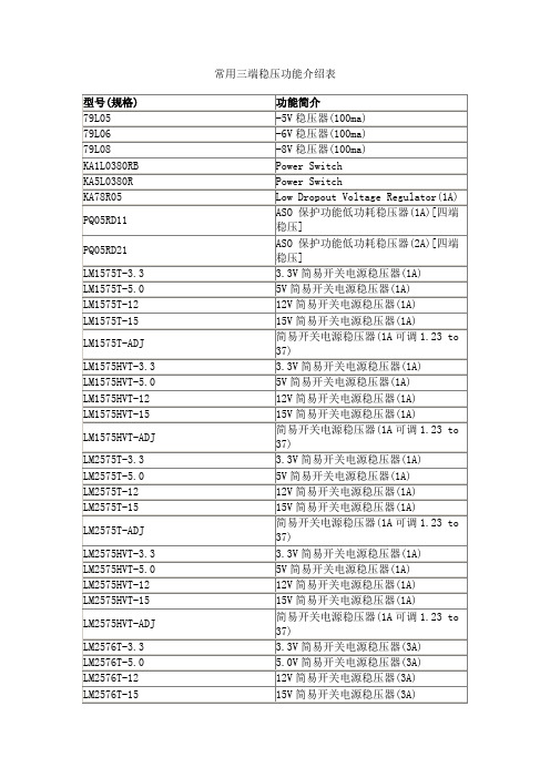
3.3V简易开关电源稳压器(1A)
LM1575T-5.0
5V简易开关电源稳压器(1A)
LM1575T-12
12V简易开关电源稳压器(1A)
LM1575T-15
15V简易开关电源稳压器(1A)
LM1575T-ADJ
简易开关电源稳压器(1A可调1.23 to 37)
LM1575HVT-3.3
LM2575HVT-ADJ
简易开关电源稳压器(1A可调1.23 to 37)
LM2576T-3.3
3.3V简易开关电源稳压器(3A)
LM2576T-5.0
5.0V简易开关电源稳压器(3A)
LM2576T-12
12V简易开关电源稳压器(3A)
LM2576T-15
15V简易开关电源稳压器(3A)
LM2576T-ADJ
79L08
-8V稳压器(100ma)
KA1L0380RB
Power Switch
KA5L0380R
Power Switch
KA78R05
Low Dropout Voltage Regulator(1A)
PQ05RD11
ASO保护功能低功耗稳压器(1A)[四端稳压]
PQ05RD21
ASO保护功能低功耗稳压器(2A)[四端稳压]
型号(规格)
功能简介
兼容型号
CA3130
高输入阻抗运算放大器
Intersil[DATA]
CA3140
高输入阻抗运算放大器
CD4573
四可编程运算放大器
MC14573
ICL7650
斩波稳零放大器
LF347(NS[DATA])
带宽四运算放大器
半导体中频变压器参数表
半导体中频变压器参数表摘要:一、半导体中频变压器参数表的概述1.半导体中频变压器的定义和作用2.半导体中频变压器参数表的重要性二、半导体中频变压器参数表的具体内容1.变压器的基本参数a.输入电压b.输出电压c.额定功率d.频率e.电压调整率f.电流调整率g.效率h.绝缘电阻i.耐压强度2.变压器的结构参数a.外形尺寸b.重量c.接线方式d.冷却方式e.防护等级三、半导体中频变压器参数表的应用领域1.通信行业2.家电行业3.工业自动化领域4.医疗设备5.其他电子设备四、半导体中频变压器参数表的注意事项1.选择合适的参数2.考虑产品的可靠性3.考虑产品的安全性4.考虑产品的兼容性正文:半导体中频变压器参数表是半导体中频变压器的重要技术文档,它详细列出了变压器的各项性能指标和技术参数,为用户选择和使用半导体中频变压器提供了重要依据。
一、半导体中频变压器参数表的概述半导体中频变压器是一种将电能从一个电路传输到另一个电路的设备,它在电子设备中有着广泛的应用。
半导体中频变压器参数表则是详细列出变压器的各项性能指标和技术参数的表格,它对于理解变压器的性能和选择合适的变压器有着重要的参考价值。
二、半导体中频变压器参数表的具体内容半导体中频变压器参数表主要包括变压器的基本参数和结构参数。
其中,基本参数包括输入电压、输出电压、额定功率、频率、电压调整率、电流调整率、效率、绝缘电阻和耐压强度等;结构参数包括外形尺寸、重量、接线方式、冷却方式、防护等级等。
三、半导体中频变压器参数表的应用领域半导体中频变压器参数表广泛应用于通信行业、家电行业、工业自动化领域、医疗设备和其他电子设备等领域。
在这些领域中,用户可以根据参数表选择合适的变压器,以满足设备的性能要求。
四、半导体中频变压器参数表的注意事项在使用半导体中频变压器参数表时,用户需要注意选择合适的参数,以保证变压器的性能和可靠性。
ADE7758数据手册中文初稿

美国模拟器件公司(ADI) ADE7758三相多功能电能计量IC (含各相信息)目录特征概述功能模块技术指标时序特征时序图表极限参数静电放电(ESD)警告引脚配置和功能描述术语典型性能特征测试电路工作原理防混叠滤波器模拟输入电流通道模数转换器(ADC)di/dt电流传感器和数字积分器峰值电流检测过载电流检测中断电压通道模数转换器(ADC)过零检测相位补偿周期测量线电压骤降(SAG)检测骤降电平设定峰值电压检测相序检测电源监视基准电路温度测量有效值计量有功功率计算无功率计算视在功率计算电能寄存比例波形采样模式校准校验和寄存器中断与MCU配合使用中断中断时序串行接口串行写入操作串行读取操作访问片内寄存器寄存器通讯寄存器操作模式寄存器(0x13)测量模式寄存器(1×14)波形模式寄存器(0×15)计算模式寄存器(0×16)线循环累加模式寄存器(0×17)中断屏蔽寄存器(0×18)中断状态寄存器(0×19)/复位中断状态寄存器(0×1A)外部尺寸定购指南历史修改记录2005年11月由版本A修改为版本B2004年9月由版本0修改为版本A修改表1 修改十六进制计数法修改图23的标题修改特征表修改电流波形增益寄存器部分修改规格表修改di/dt电流感应器和数字积分器部分修改图25修改相位补偿部分增加模拟输入部分的内容修改图57 增加图36-37,后面的图片重新排序修改图60 修改周期测量部分修改温度测量部分和有效值测量部分修改峰值电压检测部分插入表6 增加图60修改电流有效值偏移补偿部分修改电流有效值偏移补偿部分,编辑有功功率频率输出部分插入表7 增加图68,后面的图片重新排序增加公式17 修改无功功率频率输出部分修改电能累加模式部分增加图73,后面的图片重新排序修改无功功率计算部分修改使用脉冲输出进行增益校准例子增加公式32 修改公式37修改电能累加模式部分修改使用脉冲输出进行相位A的样本对相位校准修改无功功率频率输出部分修改公式56-57修改视在电能计算部分增加ADE7758中断部分修改校准部分修改有效值偏移样本对校准部分修改图76-图84 增加表20的内容修改表15修改表16修改定购指南特点高准确度:支持IEC60687,IEC61036,, IEC 61268, IEC 62053-21, IEC 62053-22, 和IEC 62053-23标准。
LPS75318低压差线性稳压器
产品特性● 1.5A输出电流● 1.8V固定输出●上电复位开漏输出●快速瞬态响应●抗总剂量100krad(Si)●CSOP18A封装●GJB597A-1996规定的B级产品概述LPS75318与TI公司TPS75318产品兼容,是内置上电复位功能的单路输出低压差线性稳压器电路(LDO)。
输入电压范围2.8V~5.5V,固定输出电压为1.8V。
电路禁用时静态电流小于40μA。
对于较大的负载电流变化(1.5A),电路具有快速瞬态响应特性。
LPS75318低压差线性稳压器电路可为DSP、FPGA、ASIC和大规模数字集成电路等提供低漏失电压及带有上电复位功能的单路输出电源。
电路无需增加任何旁路滤波电容即可提供低噪声输出电压,具有大负载电流变化快速瞬态响应,上电复位、使能功能等,可提供完整的系统电源解决方案。
绝对最大额定值输入电压范围(V IN) –0.3V~5.5VEN端口电压范围 –0.3V~5.5VRESET端口最大电压 5.5V储存温度范围(T stg) –65℃~+150℃引线耐焊接温度(10s)(T H) 300℃结温(T J) 150℃最大功耗(P D) 1.0W(常温)推荐工作条件输入电压范围(V IN) 2.8V~5.0V环境温度(T A) –55℃~+125℃电参数表除另有规定外,测试条件如下:工作温度:–55℃≤T A≤125℃;V IN =2.8V,I O UT =1mA,EN=0V,C OUT≥47μF。
参数名称测试条件极限值单位最小最大 输出电压(V O U T )2.8V≤V I N ≤5.5V,I O U T =1mA 1.764 1.836 V 输出电压负载调整率(S I ) I O U T =1mA~1.5A, V IN =5.0V – 10 mV 大电流下输出电压(V O U TA ) I O U T =1.6A, V IN =5.0V 1.76 1.84 V 静态电流(I G N D )I O U T =1mA~1.5A– 1.5 mA 输出电压线性调整率(S V )a 2.8V≤V IN ≤5.5V,I O U T =1mA– 0.3 %/V 待机模式电流(I S T B Y )EN = V IN ,T A =25℃ – 20 μAEN = V IN– 40 EN 端输入高电平(EN(H)V) 2.4 – V EN 端输入低电平(EN(L)V)– 0.6 V EN 端输入漏电流(EN I ) EN =0V 或V I N-5 5 μA RESET 端输出低电平(RESET(L)V)RESET I =1mA– 0.6 V RESET 端延迟时间(Delay T )60 180 ms RESET 端门槛电压(Trip V )T A =25℃8598%V Oa 输出电压线性调整率(%/V )=OUTOUT V V (5.5 2.8)∆⋅−;b 参数指标中的负号仅表示方向。
半导体中频变压器参数表
半导体中频变压器参数表摘要:一、半导体中频变压器概述二、半导体中频变压器的分类三、半导体中频变压器的参数四、半导体中频变压器的应用五、选择半导体中频变压器的注意事项正文:一、半导体中频变压器概述半导体中频变压器是一种应用于半导体电路中的重要电子元件,其主要作用是在中频信号处理过程中实现信号的变换和放大。
半导体中频变压器具有体积小、重量轻、效率高等优点,在半导体收音机、电视机、收录机等设备中得到了广泛应用。
二、半导体中频变压器的分类半导体中频变压器根据其用途和性能特点,可以分为以下几类:1.收音机用中频变压器:主要用于调频、调幅收音机的信号处理,如TTF-1、TTF-2、BZX-19、BZX-20 等型号。
2.彩色电视机用中频变压器:用于伴音鉴频电路、图像载波电路、同步检波电路等,如1OKR3744、1OKRC3706、1OKRC3707 等型号。
3.通用中频变压器:适用于多种电子设备,如1OTV315、1OTV216、1OLV336 等型号。
三、半导体中频变压器的参数半导体中频变压器的主要参数有:1.工作频率:指中频变压器正常工作的频率范围。
2.额定功率:指中频变压器能够承受的最大功率。
3.阻抗:指中频变压器的输入和输出阻抗,会影响信号的传输效果。
4.效率:指中频变压器将输入信号的功率转化为输出信号功率的能力,影响设备的性能。
5.温度稳定性:指中频变压器在不同温度下的性能变化。
四、半导体中频变压器的应用半导体中频变压器广泛应用于各种电子设备中,如收音机、电视机、收录机、通信设备等,主要用于信号放大、变换、滤波等功能。
五、选择半导体中频变压器的注意事项在选择半导体中频变压器时,应注意以下几点:1.确定设备的使用频率,选择工作频率匹配的中频变压器。
2.根据设备的功率需求,选择额定功率合适的中频变压器。
3.注意中频变压器的阻抗,确保信号传输效果。
4.选择效率高的中频变压器,以提高设备性能。
AD7755中文资料

元器件交易网
AD7755–SPECIFICATIONS
Parameter ACCURACY Measurement Error1 on Channel 1 Gain = 1 Gain = 2 Gain = 8 Gain = 16 Phase Error1 Between Channels V1 Phase Lead 37° (PF = 0.8 Capacitive) V1 Phase Lag 60° (PF = 0.5 Inductive) AC Power Supply Rejection1 Output Frequency Variation (CF) DC Power Supply Rejection1 Output Frequency Variation (CF) ANALOG INPUTS Maximum Signal Levels Input Impedance (DC) Bandwidth (–3 dB) ADC Offset Error1, 2 Gain Error1 Gain Error Match1 REFERENCE INPUT REFIN/OUT Input Voltage Range Input Impedance Input Capacitance ON-CHIP REFERENCE Reference Error Temperature Coefficient CLKIN Input Clock Frequency LOGIC INPUTS3 SCF, S0, S1, AC/DC, RESET, G0 and G1 Input High Voltage, V INH Input Low Voltage, VINL Input Current, IIN Input Capacitance, CIN LOGIC OUTPUTS3 F1 and F2 Output High Voltage, V OH 4.5 Output Low Voltage, V OL 0.5 CF and REVP Output High Voltage, V OH 4 Output Low Voltage, V OL 0.5
ld 中文资料
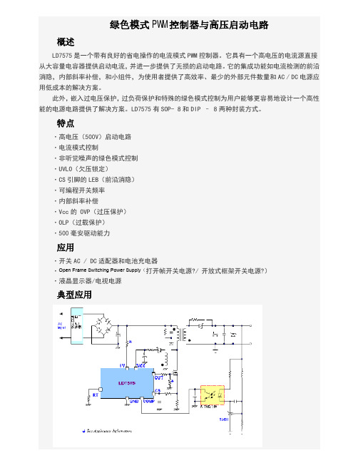
绿色模式PWM控制器与高压启动电路概述LD7575是一个带有良好的省电操作的电流模式PWM控制器。
它具有一个高电压的电流源直接从大容量电容器提供启动电流,并进一步提供了无损的启动电路。
它的集成功能如电流检测的前沿消隐,内部斜率补偿,和小组件,为使用者提供了高效率、最少的外部元件数量和AC / DC电源应用低成本的解决方案。
此外,嵌入过电压保护,过负荷保护和特殊的绿色模式控制为用户能够更容易地设计一个高性能的电源电路提供了解决方案。
LD7575有SOP- 8和DIP – 8两种封装方式。
特点·高电压(500V)启动电路·电流模式控制·非听觉噪声的绿色模式控制·UVLO(欠压锁定)·CS引脚的LEB(前沿消隐)·可编程开关频率·内部斜率补偿·Vcc的 OVP(过压保护)·OLP(过载保护)·500毫安驱动能力应用·开关AC / DC适配器和电池充电器·Open Frame Switching Power Supply(打开帧开关电源?/开放式框架开关电源?)·液晶显示器/电视电源典型应用引脚配置SOP-8和DIP-8(顶视图)订购信息LD7575是符合RoHS标准。
部件号封装顶部标记送货LD7575 PS SOP-8LD7575PS2500/磁带和卷轴LD7575 PN DIP-8LD7575PN3600 /管/箱引脚说明引脚名称功能1RT此引脚是控制开关频率。
通过一个电阻连接到地设置开关频率2COMP 电压反馈引脚(与UC384X的COMP引脚相同),通过连接的光电耦合器来闭合控制回路,实现调控。
3CS电流检测引脚,连接检测MOSFET的电流4GND接地引脚5OUT栅极驱动输出,以驱动外部MOSFET6VCC电源电压引脚7NC未连接引脚8 HV该管脚连接到大电容的正极,从而为控制器提供启动电流。
IRF7755;中文规格书,Datasheet资料
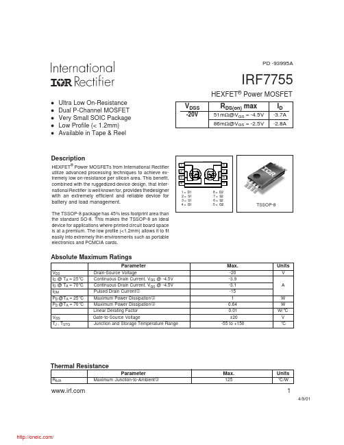
PD -93995AIRF7755HEXFET® Power MOSFETl l l l lUltra Low On-Resistance Dual P-Channel MOSFET Very Small SOIC Package Low Profile (< 1.2mm) Available in Tape & ReelVDSS-20VRDS(on) max51mΩ@VGS = -4.5V 86mΩ@VGS = -2.5VID-3.7A -2.8ADescriptionHEXFET® Power MOSFETs from International Rectifier utilize advanced processing techniques to achieve extremely low on-resistance per silicon area. This benefit, combined with the ruggedized device design, that International Rectifier is well known for, provides thedesigner1 2 3 4 1= 2= 3= 4= D1 S1 S1 G1 8= 7= 6= 5= 8 7 6 5 D2 S2 S2 G2with an extremely efficient and reliable device for battery and load management.The TSSOP-8 package has 45% less footprint area than the standard SO-8. This makes the TSSOP-8 an ideal device for applications where printed circuit board space is at a premium. The low profile (<1.2mm) allows it to fit easily into extremely thin environments such as portable electronics and PCMCIA cards.TSSOP-8Absolute Maximum RatingsParameterVDS ID @ TA = 25°C ID @ TA = 70°C IDM PD @TA = 25°C PD @TA = 70°C VGS TJ , TSTG Drain-Source Voltage Continuous Drain Current, VGS @ -4.5V Continuous Drain Current, VGS @ -4.5V Pulsed Drain Current Maximum Power Dissipation Maximum Power Dissipation Linear Derating Factor Gate-to-Source Voltage Junction and Storage Temperature RangeMax.-20 -3.9 -3.1 -15 1 0.64 0.01 ±20 -55 to +150UnitsV A W W W/°C V °CThermal ResistanceParameterRθJA Maximum Junction-to-AmbientMax.125Units°C/W14/9/01/IRF7755Electrical Characteristics @ TJ = 25°C (unless otherwise specified)V(BR)DSS∆V(BR)DSS/∆TJParameter Drain-to-Source Breakdown Voltage Breakdown Voltage Temp. Coefficient Static Drain-to-Source On-Resistance Gate Threshold Voltage Forward Transconductance Drain-to-Source Leakage Current Gate-to-Source Forward Leakage Gate-to-Source Reverse Leakage Total Gate Charge Gate-to-Source Charge Gate-to-Drain ("Miller") Charge Turn-On Delay Time Rise Time Turn-Off Delay Time Fall Time Input Capacitance Output Capacitance Reverse Transfer CapacitanceRDS(on) VGS(th) gfs IDSS IGSS Qg Qgs Qgd td(on) tr td(off) tf Ciss Coss CrssMin. -20 ––– ––– ––– -0.45 7.0 ––– ––– ––– ––– ––– ––– ––– ––– ––– ––– ––– ––– ––– –––Typ. ––– 0.011 35.3 44.3 ––– ––– ––– ––– ––– ––– 11 2.1 3.5 9 13 89 61 1090 182 124Max. Units Conditions ––– V VGS = 0V, ID = -250µA ––– V/°C Reference to 25°C, ID = -1mA 51 VGS = -4.5V, ID = -3.7A mΩ 86 VGS = -2.5V, ID = -2.8A -1.2 V VDS = VGS, ID = -250µA ––– S VDS = -10V, ID = -3.7A -15 VDS = -16V, VGS = 0V µA -25 VDS = -16V, VGS = 0V, TJ = 70°C -100 VGS = -12V nA 100 VGS = 12V 17 ID = -3.7A ––– nC VDS = -16V ––– VGS = -4.5V 14 VDD = -10V, VGS = -4.5V 20 ID = -1.0A ns 133 RG = 6.0Ω 92 RD = 10Ω ––– VGS = 0V ––– pF VDS = -15V ––– ƒ = 1.0MHzSource-Drain Ratings and CharacteristicsISISMVSD trr QrrParameter Continuous Source Current (Body Diode) Pulsed Source Current (Body Diode) Diode Forward Voltage Reverse Recovery Time Reverse Recovery ChargeMin. Typ. Max. Units ––– ––– ––– ––– ––– ––– ––– ––– 55 29 -1.0 A -15 -1.2 82 43 V ns nCConditions MOSFET symbol showing the G integral reverse p-n junction diode. TJ = 25°C, IS = -1.0A, VGS = 0V TJ = 25°C, I F = -1.0A di/dt = -100A/µs DSNotes: Repetitive rating; pulse width limited bymax. junction temperature. When mounted on 1 inch square copper board, t < 10sec. Pulse width ≤ 300µs; duty cycle ≤ 2%.2/IRF7755100VGS -7.5V -4.5V -3.5V -3.0V -2.5V -2.0V -1.75V BOTTOM -1.5V TOP100VGS -7.5V -4.5V -3.5V -3.0V -2.5V -2.0V -1.75V BOTTOM -1.5V TOP-ID, Drain-to-Source Current (A)10-ID, Drain-to-Source Current (A)1011-1.5V-1.5V 20µs PULSE WIDTH Tj = 25°C0.1 0.1 1 10 10020µs PULSE WIDTH Tj = 150°C0.1 0.1 1 10 100-VDS, Drain-to-Source Voltage (V)-VDS, Drain-to-Source Voltage (V)Fig 1. Typical Output CharacteristicsFig 2. Typical Output Characteristics1002.0RDS(on) , Drain-to-Source On Resistance (Normalized)ID = -3.9A-I D , Drain-to-Source Current (A)1.510TJ = 150 ° C TJ = 25 ° C11.00.50.1 1.0V DS = -15V 20µs PULSE WIDTH 1.5 2.0 2.5 3.00.0 -60 -40 -20VGS = -4.5V0 20 40 60 80 100 120 140 160-VGS , Gate-to-Source Voltage (V)TJ , Junction Temperature ( ° C)Fig 3. Typical Transfer CharacteristicsFig 4. Normalized On-Resistance Vs. Temperature3/IRF77551600-VGS , Gate-to-Source Voltage (V)VGS = 0V, f = 1MHz Ciss = Cgs + Cgd , Cds SHORTED Crss = Cgd Coss = Cds + Cgd10ID = -3.7AV DS =-16V8C, Capacitance (pF)1200Ciss68004400Coss Crss0 1 10 10020 0 4 8 12 16 20-VDS , Drain-to-Source Voltage (V)QG , Total Gate Charge (nC)Fig 5. Typical Capacitance Vs. Drain-to-Source VoltageFig 6. Typical Gate Charge Vs. Gate-to-Source Voltage100100-ISD , Reverse Drain Current (A)OPERATION IN THIS AREA LIMITED BY RDS(on)10-I ID , Drain Current (A)10100usTJ = 150 ° C TJ = 25 ° C1ms1110ms0.1 0.2V GS = 0 V0.4 0.6 0.8 1.0 1.2 1.40.1 0.1TC = 25 °C TJ = 150 °C Single Pulse1 10 100-VSD ,Source-to-Drain Voltage (V)-VDS , Drain-to-Source Voltage (V)Fig 7. Typical Source-Drain Diode Forward VoltageFig 8. Maximum Safe Operating Area4/IRF77554.0VDS VGSRD-ID , Drain Current (A)3.0D.U.T.+RGVDD2.0VGSPulse Width ≤ 1 µs Duty Factor ≤ 0.1 %Fig 10a. Switching Time Test Circuit1.0td(on) tr t d(off) tfVGS0.0 25 50 75 100 125 15010%TC , Case Temperature ( ° C)Fig 9. Maximum Drain Current Vs. Case Temperature90% VDSFig 10b. Switching Time Waveforms1000Thermal Response (Z thJA )100D = 0.50 0.20 0.10100.05 0.02 0.01 PDM t1 t2 SINGLE PULSE (THERMAL RESPONSE) Notes: 1. Duty factor D = t 1 / t 2 2. Peak TJ = P DM x ZthJA + TA 0.01 0.1 1 10 10010.1 0.000010.00010.001t1 , Rectangular Pulse Duration (sec)Fig 11. Maximum Effective Transient Thermal Impedance, Junction-to-Ambient5/IRF7755Ω) RDS ( on ) , Drain-to-Source On Resistance (() RDS(on), Drain-to -Source On Resistance Ω0.1600.2000.1200.1500.0800.100VGS = -2.5VID = -3.7A0.0400.050VGS = -4.5V0.000 2.0 3.0 4.0 5.0 6.0 7.0 8.00.000 0 5 10 15 -ID , Drain Current ( A )-VGS, Gate -to -Source Voltage (V)Fig 12. Typical On-Resistance Vs. Gate VoltageFig 13. Typical On-Resistance Vs. Drain CurrentCurrent Regulator Same Type as D.U.T.50KΩQG12V.2µF.3µF10 VQGS VG QGDVGS-3mAD.U.T.+VDSIGIDCurrent Sampling ResistorsChargeFig 14a. Basic Gate Charge WaveformFig 14b. Gate Charge Test Circuit6/IRF7755TSSOP-8 Part Marking InformationEXAMPLE: T HIS IS AN IRF7702LOT CODE (XX) PART NUMBERDAT E CODE (YW)XXYW 7702T ABLE 1 WORK WEEK 1-26, NUMERIC YEAR CODE (1,2, ....ET C.) YEAR 2001 2002 2003 1994 1995 1996 1997 1998 1999 2000 Y 1 2 3 4 5 6 7 8 9 0 WORK WEEK 01 02 03 04 W A B C DDAT E CODE EXAMPLES : 9503 = 5C 9532 = EF24 25 26X Y ZT ABLE 2 WORK WEEK 27-52, ALPHANUMERIC YEAR CODE (A,B, ...ETC.) YEAR 2001 2002 2003 1994 1995 1996 1997 1998 1999 2000 Y A B C D E F G H J K WORK WEEK 27 28 29 30 W A B C D50 51 52X Y ZTSSOP-8 Tape and Reel8LT SSOP (MO-153AA)16 mmØ 13"16mm 8 mm FEED DIRECT ION NOT ES: 1. T APE & REEL OUT LINE CONFORMS T O EIA-481 & EIA-541.7/IRF7755TSSOP-8 Package OutlineData and specifications subject to change without notice. This product has been designed and qualified for the consumer market. Qualification Standards can be found on IR’s Web site.IR WORLD HEADQUARTERS: 233 Kansas St., El Segundo, California 90245, USA Tel: (310) 252-7105 TAC Fax: (310) 252-7903 Visit us at for sales contact information. 4/018/分销商库存信息:IR IRF7755。
cse7758单项电度表电路芯片资料
CSE7758用户手册V1.0深圳市芯海科技有限公司2007年5月10日目录图形 (3)表格 (3)1主要特点 (4)2功能概述 (4)3原理框图 (5)4管脚定义及功能描述 (5)4.1 管脚排列 (5)4.2 管脚定义及功能描述 (5)5性能指标与实测结果 (6)5.1 CSE7758性能指标 (6)5.2 CSE7758实际测试结果 (7)5.2.1测量准确度 (7)5.2.2参考电压温度特性 (9)6芯片工作原理 (9)6.1 信号流 (9)6.2 功率因子影响 (10)6.3 非正弦电压电流输入 (10)7模拟输入 (11)7.1 电流通道 (11)7.1.1电压输入范围 (11)7.1.2电流传感信号接入方法 (11)7.2 电压通道 (12)7.2.1信号输入范围 (12)7.2.2信号接入方法 (12)8电源电压的检测 (13)9高通滤波与失调电压影响 (13)10功率到频率转换 (14)11输出频率与输入信号的关系 (15)11.1 F1、F2输出频率与输入信号的关系 (15)12电表应用时的参数设置 (16)12.1 锰铜采样电阻的选择 (16)12.2 输出频率与量程的关系 (16)12.3 F1,F2最大输出频率 (17)13F1,F2,CF输出时序 (17)14启动阈值电流 (19)15极限工作条件 (19)16CSE7758封装 (19)17附录1:电表设计时的参数设置 (20)17.1 第1步:首先计算电流通道最大输入电压V1Pp (20)17.2 第2步:计算最大输出频率 (21)17.3 第3步:计算电压通道的输入电压 (21)图形图1.C SE7758功能框图 (5)图2.C SE7758管脚图(顶视图) (5)图3.C SE7758精度测试电路 (7)图4.C SE7758测量精度(PGA=16) (7)图5.C SE7758变频测试结果1(G=16,PF=1) (8)图6.C SE7758变频测试结果2(G=16,PF=0.8C) (8)图7.C SE7758变频测试结果3(G=16,PF=0.5L) (8)图8.C SE7758基准电压随温度变化图 (9)图9.C SE7758信号流图 (9)图10.电流通道接入方法一(电阻采样) (12)图11.电流通道接入方法二(电流互感CT) (12)图12.电压通道接入方法一(电阻分压) (13)图13.电压通道接入方法二(变压器感应).......................................错误!未定义书签。
电磁炉的稳压器

电磁炉的稳压器作用:稳定电压稳压器是电磁炉的主要部件之一。
电磁炉常用稳压器是三端稳压器。
下面以78系列和79系列三端稳压器为例,对三端稳压器做一个调查。
78系列和79系列三端集成稳压器内部有过热、过流保护电路,外围元件少,性能优良、体积小、价格低,故在很多电路中广泛应用,如在有线电视系统的卫星接收机、调制器、解调器、放大器等电源部分都可以用到。
78系列和79系列稳压器,它的封装形式为to-220.它有一系列固定的电压输出,应用非常广泛。
每种类型由于内部电流的限制,以及过热保护和安全区的保护,使它基本上不会损坏。
如果能够提供足够的散热片,它们能够提供大于1.5A的输出电流。
虽然是按照固定电压值来设计的,但是当接入适当的外部电器后,就能获得不同的电压和电流。
它的特点:最大输出电流为1.5A输出电压为5V, 6V, 8V, 9V, 10V, 12V, 15V, 18V, 24V热过载保护短路保护输出晶体管安全工作去保护三端稳压器:原理:常见到三端稳压集成电路有正电压输出的78系列和负电压输出的79系列。
故名思义,三端IC是指这种稳压用的集成电路只有三条引脚输出,分别是输入端、接地端和输出端。
它的样子象是普通的三极管,TO-220的标准封装,也有9013样子的TO-92封装。
用78/79系列三端稳压IC来组成稳压电源所需的外围元件极少,电路内部还有过流、过热及调整管的保护电路,使用起来可靠、方便,而且价格便宜。
该系列集成稳压IC型号中的78或79后面的数字代表该三端集成稳压电路的输出电压,如7806表示输出电压为正6V,7909表示输出电压为负9V。
上图是78系列稳压器的电路原理方框图, 它与一般分立件组成的串联调整式稳压电源十分相似, 区别在于增加了启动电路、恒流源以及保护电路。
为了使稳压器能在比较大的电压变化范围内正常工作,在基准电压形成和误差放大部分设置了恒流源电路,启动电路的作用就是为恒流源建立工作点,Rsc是过流保护取样电阻,RA,RB组成电压取样电路,实际电路是由一个电阻网络构成,在输出不同电压稳压器中,采用不同的串并联接法,形成不同的分压比,通过误差放大之后去控制调整管的工作状态,以形成和稳定一系列预定的输出电压,因此上图中RA画为可调电阻。
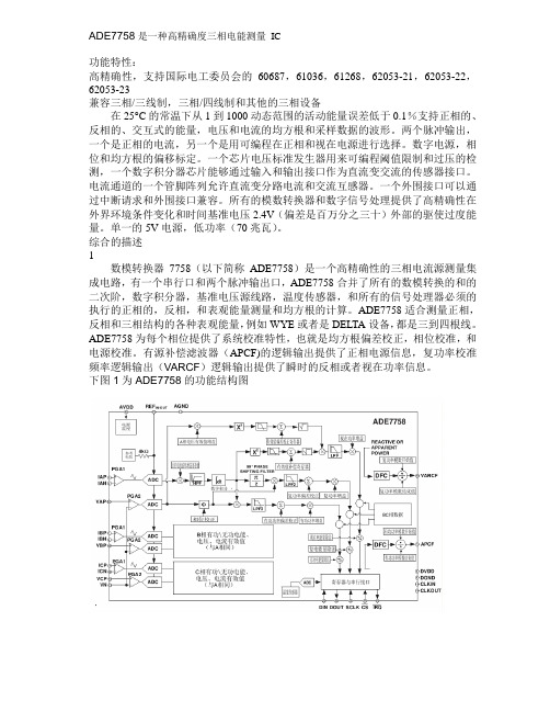
ADE7758中文
ADE7758是一种高精确度三相电能测量IC功能特性:高精确性,支持国际电工委员会的60687,61036,61268,62053-21,62053-22,62053-23兼容三相/三线制,三相/四线制和其他的三相设备在25°C的常温下从1到1000动态范围的活动能量误差低于0.1%支持正相的、反相的、交互式的能量,电压和电流的均方根和采样数据的波形。
两个脉冲输出,一个是正相的电流,另一个是用可编程在正相和视在电源进行选择。
数字电源,相位和均方根的偏移标定。
一个芯片电压标准发生器用来可编程阈值限制和过压的检测,一个数字积分器芯片能够通过输入和输出接口作为直流变交流的传感器接口。
电流通道的一个管脚阵列允许直流变分路电流和交流互感器。
一个外围接口可以通过中断请求和外围接口兼容。
所有的模数转换器和数字信号处理提供了高精确性在外界环境条件变化和时间基准电压2.4V(偏差是百万分之三十)外部的驱使过度能量。
单一的5V电源,低功率(70兆瓦)。
综合的描述1数模转换器7758(以下简称ADE7758)是一个高精确性的三相电流源测量集成电路,有一个串行口和两个脉冲输出口,ADE7758合并了所有的数模转换的和的二次阶,数字积分器,基准电压源线路,温度传感器,和所有的信号处理器必须的执行的正相的,反相,和表观能量测量和均方根的计算。
ADE7758适合测量正相,反相和三相结构的各种表观能量,例如WYE或者是DELTA设备,都是三到四根线。
ADE7758为每个相位提供了系统校准特性,也就是均方根偏差校正,相位校准,和电源校准。
有源补偿滤波器(APCF)的逻辑输出提供了正相电源信息,复功率校准频率逻辑输出(VARCF)逻辑输出提供了瞬时的反相或者视在功率信息。
下图1为ADE7758的功能结构图概括描述ADE有一个波形采样寄存器,允许直接访问AD转换器的输出。
这部分为短周期的低或高电压变化集成了检测线路。
电压的阀值电平和周期(半线回路的条数)的变化都是用户可编程的。
单芯片功率监控IC
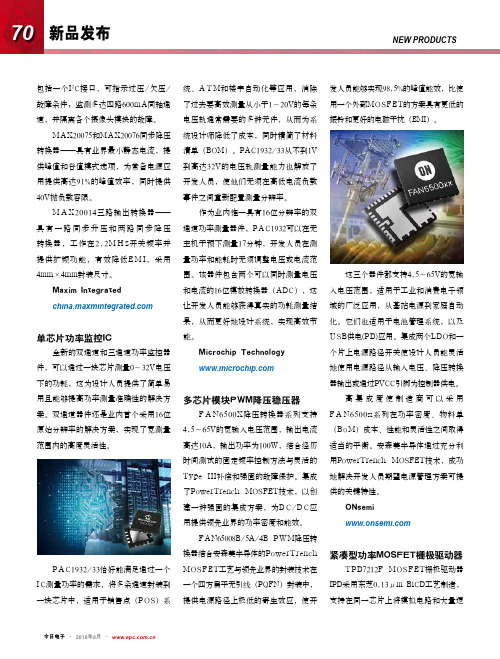
新品发布NEW PRODUCTS今日电子 · 2018年8月 · 包括一个I 2C接口,可指示过压/欠压/故障条件;监测多达四路600m A同轴通道,并隔离各个摄像头模块的故障。
MAX20075和MAX20076同步降压转换器——具有业界最小静态电流,提供峰值和谷值模式选项,为常备电源应用提供高达91%的峰值效率,同时提供40V抛负载容限。
M A X20014三路输出转换器——具有一路同步升压和两路同步降压转换器,工作在2.2M H z开关频率并提供扩频功能,有效降低E M I,采用4mm×4mm封装尺寸。
Maxim Integrated单芯片功率监控IC全新的双通道和三通道功率监控器件,可以通过一块芯片测量0~32V电压下的功耗,这为设计人员提供了简单易用且能够提高功率测量准确性的解决方案。
双通道器件还是业内首个采用16位原始分辨率的解决方案,实现了宽测量范围内的高度灵活性。
P A C1932/33恰好能满足通过一个I C测量功率的需求,将多条通道封装到一块芯片中,适用于销售点(P O S)系统、A T M和楼宇自动化等应用,消除了过去要高效测量从小于1~20V的每条电压轨通常需要的多种元件,从而为系统设计师降低了成本,同时精简了材料清单(BOM)。
PAC1932/33从不到1V 到高达32V的电压轨测量能力也解放了开发人员,使他们无须在高低电流负载事件之间重新配置测量分辨率。
作为业内惟一具有16位分辨率的双通道功率测量器件,PAC1932可以在无主机干预下测量17分钟,开发人员在测量功率和能耗时无须调整电压或电流范围。
该器件包含两个可以同时测量电压和电流的16位模数转换器(ADC),这让开发人员能够获得真实的功耗测量结果,从而更好地设计系统,实现高效节能。
Microchip Technology多芯片模块PWM降压稳压器F A N6500X降压转换器系列支持4.5~65V的宽输入电压范围,输出电流高达10A,输出功率为100W,结合经历时间测试的固定频率控制方法与灵活的Type III补偿和强固的故障保护。
Intel Socket 775 处理器 i945P 芯片组 主板 说明书
V1.0 中文版2006年02月10日商標所有的產品註冊商標及公司名稱皆屬其原公司所有產品內容若有更改時,恕不另行通知用戶手冊Intel Socket 775 處理器Intel i945P 芯片組60005845LDA10目 錄第一章第一章 簡介包裝內容.........................................1-1主板概貌.........................................1-2系統方塊圖.......................................1-5第二章第二章 規格主板規格.........................................2-1第三章第三章 安裝主板元件配置圖...................................3-1CPU安裝...........................................3-2跳線設定..........................................3-4系統內存配置.....................................3-5VGA卡安裝........................................3-7設備接口.........................................3-9Thermo Stick (可選).............................3-15Power-開啟/關閉..................................3-16ACPI S3 (Suspend To RAM)功能...................3-17第四章第四章 BIOS 設定說明..............................................4-1標準CMOS設置.....................................4-2BIOS高級設置.....................................4-3芯片組高級設置...................................4-5集成週邊設置.....................................4-7系統電源管理設置.................................4-11即插即用/PCI/PCI-E設置..........................4-13系統狀態偵測設置.................................4-14PowerBIOS功能設置...............................4-16B I O S 預設/優化參數設置...........................4-19密碼設置.........................................4-19儲存參數設置並退出..............................4-20第五章第五章 RAID RAID配置配置簡易說明.........................................5-1啟動RAID功能.....................................5-3第六章第六章驅動程序安裝簡易安裝步驟.....................................6-1R e a l t e k 音頻控制面板簡易使用說明................6-2附錄附錄附錄A 刷新主板BIOS .....................................A-1常用除錯卡代碼一覽表解決方法1.重新檢查BIOS 是否有反插2.重新檢查所有硬件配件是否插好3.換主板代 碼碼可能問題1.BIOS 插反2.用錯BIOS3.主板有問題4.ADD-ON 卡(配卡)沒插好C1h - C 5h1.MEMORY 沒插好2.挑MEMORY3.MEMORY 損壞 1.重新安裝內存條2.更換內存條1.VGA BIOS 有問題2.VGA 卡沒插好FFh or CFh2Dh1.換VGA 卡2.檢查VGA 卡是否有插好1.超頻失敗26h 1.清除CMOS 或按Insert 鍵開機1.設定鍵盤控制器失敗2.RTC 失敗07h - 12h1.重新安插鍵盤或鼠標2.更換電池(11)(9)若你的包裝內物品有任何的損壞或短缺情形,請與經銷商聯絡。
- 1、下载文档前请自行甄别文档内容的完整性,平台不提供额外的编辑、内容补充、找答案等附加服务。
- 2、"仅部分预览"的文档,不可在线预览部分如存在完整性等问题,可反馈申请退款(可完整预览的文档不适用该条件!)。
- 3、如文档侵犯您的权益,请联系客服反馈,我们会尽快为您处理(人工客服工作时间:9:00-18:30)。
元器件交易网
IMPORTANT NOTICE
Texas Instruments and its subsidiaries (TI) reserve the right to make changes to their products or to discontinue
any product or service without notice, and advise customers to obtain the latest version of relevant information
to verify, before placing orders, that information being relied on is current and complete. All products are sold
subject to the terms and conditions of sale supplied at the time of order acknowledgement, including those
pertaining to warranty, patent infringement, and limitation of liability.
TI warrants performance of its semiconductor products to the specifications applicable at the time of sale in
accordance with TI’s standard warranty. Testing and other quality control techniques are utilized to the extent
TI deems necessary to support this warranty. Specific testing of all parameters of each device is not necessarily
performed, except those mandated by government requirements.
CERTAIN APPLICATIONS USING SEMICONDUCTOR PRODUCTS MAY INVOLVE POTENTIAL RISKS OF
DEATH, PERSONAL INJURY, OR SEVERE PROPERTY OR ENVIRONMENTAL DAMAGE (“CRITICAL
APPLICATIONS”). TI SEMICONDUCTOR PRODUCTS ARE NOT DESIGNED, AUTHORIZED, OR
WARRANTED TO BE SUITABLE FOR USE IN LIFE-SUPPORT DEVICES OR SYSTEMS OR OTHER
CRITICAL APPLICATIONS. INCLUSION OF TI PRODUCTS IN SUCH APPLICATIONS IS UNDERSTOOD TO
BE FULLY AT THE CUSTOMER’S RISK.
In order to minimize risks associated with the customer’s applications, adequate design and operating
safeguards must be provided by the customer to minimize inherent or procedural hazards.
TI assumes no liability for applications assistance or customer product design. TI does not warrant or represent
that any license, either express or implied, is granted under any patent right, copyright, mask work right, or other
intellectual property right of TI covering or relating to any combination, machine, or process in which such
semiconductor products or services might be or are used. TI’s publication of information regarding any third
party’s products or services does not constitute TI’s approval, warranty or endorsement thereof.
Copyright © 1999, Texas Instruments Incorporated。
