SCART interface-II
数字视频接口(DVI、HDMI)介绍

在投影机或等离子电视机或近距离观看的大屏幕显示器上,我们才需要采用数字视频接口(DVI)技术来得到最好的图像质量。
也就是讲,在远距离观看的显示设备上,数字视频接口相比模拟视频接口至少需要在42”以上800x600以上清晰度的电视机才逐渐取得优势,在42”以下的显示设备上,数字视频接口并没有太大的意义。
2、由于复合视频信号是将亮度信号和色度信号采用频谱间置方法复合在一起,导致亮色串扰、清晰度降低等问题。因此,随着摄影机、S-VHS录像机的发展,出现了S端子接口。将亮度信号Y和色度信号C分开传输。确保亮度信号不会受到色度信号的干扰。
3、虽然S端子用来传输现在的视频信号已经很好了,可是真正的AV玩家还是不满足。色度信号是将色差信号调制在色负载波上得到的。为什么不直接传输色差信号呢?于是电器制造商根据各自的情况,发展自己的视频接口。欧洲厂商统一起来,使用SCART接口,传输的是RGB三原色信号。而日本厂商发展D端子,传输的是色差分量信号。现在SCART成了欧洲电器的标准接口,而日本的高档DVD机和电视机都具备D端子。美国人则延续了使用RCA端子的传统,使用3个RCA端子来传输色差分量信号。由于美国在数字视听领域的强大势力,3 RCA色差分量数字在欧洲和日本以外的地区成了DVD播放机的标准输出接口。即使在日本和欧洲,大部分DVD播放机也具备色差分量接口。而我国厂商则在较高档的逐行DVD机装备了VGA输出接口。实际上在DVD机上装备VGA接口在美国是违反版权保护法的,因为现在在VGA接口上还没有版权保护措施,因此不允许使用VGA接口输出高质量的视频信号。这也就是为什么我们在飞利浦、SONY、松下、先锋等进口机器上看不到VGA接口的原因,非不能也,是不为也。
TV视频接口介绍

TV 常用外部匹配设备与接口目前公司生产的LCD-TV 有销美、销欧、销日、及销大陆。
依其销向的不同,其接口的配置也不同。
各销向典型的接口配置如下图:一、销大陆的接口的标准接口( 图一、销大陆的接口示意图)1、 RF 射频端子RF 射频端子是最早在电视机上出现的,原意为无线电射频(Radio Frequency ),这种端子虽然历史悠久,对其外形和结构人人熟悉,但并不一定都了解它的特点。
实际上,RF 射频端子是一种高频信号连接端子。
由于电视的视频信号和音频信号需要通过发射进行远距离传播,故此必须使用高频信号。
而高频调制时两种信号是混合的。
最后解调出来信号质量大大下降。
因此,RF 射频端子连接的电视机的最终图像效果,质量是最差。
因此,用户在使用视频播放机如录像机、LD 机与电视机连接时,如果电视机不是最老式的只有RF 接口的,一定不要用RF 接口,而要用A V 接口或其他更高档的接口。
Y/Pb/Pr 色差分量接口 S-VIDEO 接口CVBS 输入 Audio 接口2、复合视频V端子V端子是Video(视频)端子的简称,它是声/画分离的视频端子,只管图像信号的传输,而音频信号通过另外的端子连接。
最常见的是被称作A V端子的接口组,它是由三个独立的RCA插头(又叫莲花接口RCAjack)组成的,其中的V接口连接复合视频信号,为黄色插口;L 接口连接左声道声音信号信号,为白色插口;R接口连接右声道声音信号,为红色插口。
这种复合视频信号没有经过RF射频信号那些调制、放大、检波、解调等过程,信号保真度相对较高,一般可达350-450线。
S端子相对于普通视频端子来说,被称为超级视频端子(Super Video)也就是S端子的来源。
由于复合视频信号是将亮度信号和色度信号采用频谱间置方法复合在一起,导致亮色串扰、清晰度降低等问题。
因此,随着摄影机、S-VHS录像机的发展,出现了S端子接口。
将亮度信号Y和色度信号C分开传输。
Analog Devices视频解码器连接MIPI CSI-2接收器的设计考虑说明书
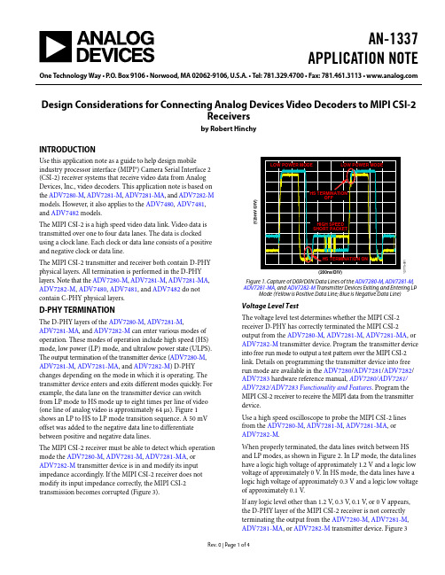
AN-1337APPLICATION NOTE One Technology Way•P.O.Box9106•Norwood,MA02062-9106,U.S.A.•Tel:781.329.4700•Fax:781.461.3113•Design Considerations for Connecting Analog Devices Video Decoders to MIPI CSI-2Receiversby Robert HinchyINTRODUCTIONUse this application note as a guide to help design mobileindustry processor interface (MIPI®) Camera Serial Interface 2(CSI-2) receiver systems that receive video data from AnalogDevices, Inc., video decoders. This application note is based onthe ADV7280-M, ADV7281-M, ADV7281-MA, and ADV7282-Mmodels. However, it also applies to the ADV7480, ADV7481,and ADV7482 models.The MIPI CSI-2 is a high speed video data link. Video data istransmitted over one to four data lanes. The data is clockedusing a clock lane. Each clock or data lane consists of a positiveand negative clock or data line.The MIPI CSI-2 transmitter and receiver both contain D-PHYphysical layers. All termination is performed in the D-PHY layers. Note that the ADV7280-M, ADV7281-M, ADV7281-MA, ADV7282-M, ADV7480, ADV7481, and ADV7482 do not contain C-PHY physical layers.D-PHY TERMINATIONThe D-PHY layers of the ADV7280-M, ADV7281-M,ADV7281-MA, and ADV7282-M can enter various modes of operation. These modes of operation include high speed (HS) mode, low power (LP) mode, and ultralow power state (ULPS). The output termination of the transmitter device (ADV7280-M, ADV7281-M, ADV7281-MA, and ADV7282-M) D-PHY changes depending on the mode in which it is operating. The transmitter device enters and exits different modes quickly. For example, the data lane on the transmitter device can switch from LP mode to HS mode up to eight times per line of video (one line of analog video is approximately 64 μs). Figure 1 shows an LP to HS to LP mode transition sequence. A 50 mV offset was added to the negative data line to differentiate between positive and negative data lines.The MIPI CSI-2 receiver must be able to detect which operation mode the ADV7280-M, ADV7281-M, ADV7281-MA, or ADV7282-M transmitter device is in and modify its input impedance accordingly. If the MIPI CSI-2 receiver does not modify its input impedance correctly, the MIPI CSI-2 transmission becomes corrupted (Figure 3).12775-1(125mV/DIV)Figure 1. Capture of D0P/D0N Data Lines of the ADV7280-M, ADV7281-M, ADV7281-MA, and ADV7282-M Transmitter Devices Exiting and Entering LP Mode (Yellow is Positive Data Line; Blue is Negative Data Line) Voltage Level TestThe voltage level test determines whether the MIPI CSI-2 receiver D-PHY has correctly terminated the MIPI CSI-2 output from the ADV7280-M, ADV7281-M, ADV7281-MA, or ADV7282-M transmitter device. Program the transmitter device into free run mode to output a test pattern over the MIPI CSI-2 link. Details on programming the transmitter device into free run mode are available in the ADV7280/ADV7281/ADV7282/ ADV7283 hardware reference manual, ADV7280/ADV7281/ ADV7282/ADV7283Functionality and Features. Program the MIPI CSI-2 receiver to receive the MIPI data from the transmitter device.Use a high speed oscilloscope to probe the MIPI CSI-2 lines from the ADV7280-M, ADV7281-M, ADV7281-MA, orADV7282-M.When properly terminated, the data lines switch between HS and LP modes, as shown in Figure 2. In LP mode, the data lines have a logic high voltage of approximately 1.2 V and a logic low voltage of approximately 0 V. In HS mode, the data lines have a logic high voltage of approximately 0.3 V and a logic low voltage of approximately 0.1 V.If any logic level other than 1.2 V, 0.3 V, 0.1 V, or 0 V appears, the D-PHY layer of the MIPI CSI-2 receiver is not correctly terminating the output from the ADV7280-M, ADV7281-M, ADV7281-MA, or ADV7282-M transmitter device. Figure 3AN-1337Application Noteshows an example of the MIPI CSI-2 positive data line output from the transmitter device for a poorly terminated receiver. When the transmitter device (ADV7280-M , ADV7281-M ,ADV7281-MA , or ADV7282-M ) is programmed, the MIPI CSI-2 clock lane exits LP mode and enters HS mode. Unless the transmitter device is manually programmed to enter LP mode or is reset, the clock lane remains in HS mode. If any logic level other than 0.3 V or 0.1 V appears on the MIPI CSI-2 clock lines, the D-PHY layer of the MIPI CSI-2 receiver does not correctly terminate the output from the transmitter device.Capture of Positive Data Line in High Speed and Low Power ModesFigure 2 and Figure 3 show the difference between a correct and an incorrect termination of the MIPI CSI-2 signal by the D-PHY layer in the MIPI CSI-2 receiver.12775-002(200m V /D I V )Figure 2. Positive Data Line (D0P) Output from the ADV7280-M , ADV7281-M , ADV7281-MA , and ADV7282-M Transmitter Devices; Correct MIPI CSI-2Receiver Termination12775-003(200m V /D I V )Figure 3. Positive Data Line (D0P) Output from the ADV7280-M , ADV7281-M , ADV7281-MA , and ADV7282-M Transmitter Devices; Incorrect MIPI CSI-2Receiver TerminationD-PHY Mode Detection TestTo test that the MIPI CSI-2 receiver can detect each operation mode, manually program the ADV7280-M , ADV7281-M , ADV7281-MA , or ADV7282-M transmitter device to enter HS mode, LP mode, and ULPS. Then, test the MIPI CSI-2 receiverto verify that it can correctly detect the operation mode of the transmitter device.Refer to the ADV7280/ADV7281/ADV7282/ADV7283hardware reference manual, ADV7280/ADV7281/ADV7282/ ADV7283 Functionality and Features , for details on manually programming the ADV7280-M , ADV7281-M , ADV7281-MA , or ADV7282-M to enter HS mode, LP mode, and ULPS.Clock Lane Low Power to High Speed Transition Some MIPI CSI-2 receivers wait for an LP to HS modetransition on the MIPI CSI-2 clock lane before starting video capture. However, the LP to HS mode transition on the MIPI CSI-2 clock lane occurs only once on the ADV7280-M , ADV7281-M , ADV7281-MA , and ADV7282-M immediately after they are initially programmed.If the MIPI CSI-2 receiver is initialized after the transmitter device is initialized, the MIPI CSI-2 may never detect the LP to HS mode transition on the clock lane from the transmitter device. If the MIPI CSI-2 receiver does not detect the LP to HS mode transition, it may never start video capture.To overcome this issue, manually program the clock lane of the ADV7280-M , ADV7281-M , ADV7281-MA , or ADV7282-M to enter and then exit LP mode. The easiest way to do this is by toggling the CSITX_PWRDN bit (Address 0x00, Bit 7).The MIPI CSI-2 receiver then recognizes an LP to HS mode transition and begins video capture.DESIGN OF MIPI CSI-2 RECEIVER SYSTEMThe following sections provide tips on debugging issues with the MIPI CSI-2 receiver system that is receiving video data from the ADV7280-M , ADV7281-M , ADV7281-MA , or ADV7282-M .Lock StatusWhen an analog video source is connected to the ADV7280-M , ADV7281-M , ADV7281-MA , or ADV7282-M video decoder, it can take the video decoder a period of time before it locks to the incoming analog video. This period of time can take up to 250 ms in fast switch mode and more than 500 ms in autodetect mode. The ADV7280-M , ADV7281-M , ADV7281-MA , or ADV7282-M outputs spurious data over the MIPI CSI-2 link until the device locks to the incoming analog video. It is recommended that the MIPI CSI-2 receiver system be set to ignore the output from the ADV7280-M , ADV7281-M , ADV7281-MA , or ADV7282-M until the ADV7280-M ,ADV7281-M , ADV7281-MA , or ADV7282-M has locked to the analog video.The FSC_LOCK, LOST_LOCK, and IN_LOCK bits (Register 0x10, Bits[2:0]) indicate whether the ADV7280-M , ADV7281-M , ADV7281-MA , or ADV7282-M transmitter device has locked to the analog video source.Use the INTRQ hardware interrupt pin in conjunction with the FSC_LOCK, LOST_LOCK, and IN_LOCK bits to verify when a lock event has occurred. Using the INTRQ hardware interruptApplication Note AN-1337pin saves the MIPI CSI-2 receiver from constantly polling the FSC_LOCK, LOST_LOCK, and IN_LOCK bits.Use the CSITX_PWRDN bit to stop the MIPI CSI-2 output from the ADV7280-M, ADV7281-M, ADV7281-MA, orADV7282-M. Stop the MIPI CSI-2 output until the ADV7280-M, ADV7281-M, ADV7281-MA, or ADV7282-M has locked to the analog video source, as indicated by the INTRQ hardware interrupt pin.For more information on the CSITX_PWRDN, FSC_LOCK, LOST_LOCK, and IN_LOCK bits and on the INTRQ hardware interrupt pin, see the ADV7280/ADV7281/ADV7282/ADV7283 hardware reference manual, ADV7280/ADV7281/ ADV7282/ADV7283Functionality and Features. DeinterlacerBy default, the ADV7280-M, ADV7281-M, ADV7281-MA, and ADV7282-M transmitter devices output video data in an interlaced format in the YCbCr 4:2:2 color space. In most applications, the MIPI CSI-2 receiver system requires a deinterlacing function. The most common way of performing this function is by using a frame buffer. For example, an odd field and an even field of video are transmitted into a memory buffer in the MIPI CSI-2 receiver system. The data stored in the memory buffer is then analyzed as a complete progressive frame of video by the MIPI CSI-2 receiver system.Alternatively, the ADV7280-M and ADV7282-M transmitter devices have an integrated deinterlacer. This is referred to as the interlaced to progressive (I2P) core in the ADV7280-M and ADV7282-M data sheets and in the hardware reference manual, ADV7280/ADV7281/ADV7282/ADV7283Functionality andFeatures. Using the I2P cores on the ADV7280-M and the ADV7282-M transmitter devices and programming them to output in progressive mode eliminates the need for deinterlacing in the MIPI CSI-2 receiver system.The I2P core of the ADV7280-M and ADV7282-M interpolates between two lines of video. An algorithm is used to smooth the resulting image to minimize low angle artifacts.Odd and Even Fields of Different LengthsThe ADV7280-M, ADV7281-M, ADV7281-MA, andADV7282-M video decoders output video over the MIPI CSI-2 stream. However, the video timing is based on the ITU-R BT.656-3 or ITU-R BT.656-4 standard.In interlaced mode, an NTSC video source results in theADV7280-M, ADV7281-M, ADV7281-MA, and ADV7282-M transmitter devices outputting video where the odd fields are one line longer than the even fields. This difference occurs with NTSC sources only. PAL sources result in even and odd fields of the same length.When designing video frame buffers in the MIPI CSI-2 receiver system, the even and odd fields can be of different length. However, the ADV7280-M and ADV7282-M models with I2P cores can be programmed to output progressive video. In progressive mode, all fields output by the transmitter devices are the same length.For more information on the video output timing or the I2P core, see the ADV7280/ADV7281/ADV7282/ADV7283 hardware reference manual, ADV7280/ADV7281/ADV7282/ ADV7283Functionality and Features.Video Frame Buffer OverflowsMost MIPI CSI-2 receivers contain a video frame buffer. Each video frame from the ADV7280-M, ADV7281-M, ADV7281-MA, or ADV7282-M transmitter device is stored in a memory buffer before being analyzed by the MIPI CSI-2 receiver.Under certain circumstances (if the analog video source is disconnected, for example), the ADV7280-M, ADV7281-M, ADV7281-MA, or ADV7282-M transmitter device can output video frames with a nonstandard number of lines because the transmitter device is designed to be effective at processing poor video sources.When the CVBS source is not present, the ADV7280-M,ADV7281-M, ADV7281-MA, or ADV7282-M transmitter device continues to output MIPI CSI-2 video data and enters a search mode. When the device is in search mode, any noise on the CVBS input is tested to determine whether it is an analog video signal. When in search mode, the transmitter device outputs frames that are much longer than standard.The ADV7280-M, ADV7281-M, ADV7281-MA, or ADV7282-M transmitter device remains in search mode for approximately 1 sec in autodetect mode. In fast switch mode, the transmitter device remains in search mode for approximately six fields of video.If a valid analog video source is not detected after the period where the ADV7280-M, ADV7281-M, ADV7281-MA, or ADV7282-M is in search mode, the device determines that no video source is present. The device then exits search mode and enters free run mode. In free run mode, the ADV7280-M, ADV7281-M, ADV7281-MA, or ADV7282-M transmitter device outputs test pattern video frames with standard timing. These nonstandard video frames output during search mode can cause a buffer overflow event in the MIPI CSI-2 receiver. One of the best solutions to prevent a buffer overflow is to use a line counter.The line counter is a control loop in the MIPI CSI-2 receiver that counts the number of lines being output per frame by the ADV7280-M, ADV7281-M, ADV7281-MA, or ADV7282-M transmitter device. If the number of lines output per frame exceeds a limit, the MIPI CSI-2 receiver ignores the output from the transmitter device until the next frame start packet. Choose the line number limit so that the video buffer memory of the MIPI CSI-2 receiver does not overflow and so that standard video sources are not attenuated.AN-1337 Application NoteBy default, the MIPI CSI-2 frame start/end packets and the MIPI line start/end packets are output by the ADV7280-M, ADV7281-M, ADV7281-MA, or ADV7282-M transmitter device.Free Run ModeWhen the ADV7280-M, ADV7281-M, ADV7281-MA, or ADV7282-M transmitter device is programmed into free run mode, the device ignores the analog video input and outputs a fixed test pattern. Free run mode can help customers debug issues with their MIPI CSI-2 receiver systems. A number of test patterns are available. For more information, see the ADV7280/ ADV7281/ADV7282/ADV7283 hardware reference manual, ADV7280/ADV7281/ADV7282/ADV7283Functionality and Features.LAYOUT OF MIPI CSI-2 TRACESMIPI CSI-2 is designed as a chip to chip interface; therefore, it does not transmit over long distances. The D-PHY specification defines the maximum lane flight time to 2 ns. Using standard printed circuit board (PCB) materials and design rules (for example, transmitting MIPI CSI-2 through a microstripline on a standard FR4 PCB), results in a maximum trace length of 25 cm to 30 cm. Therefore, keep the MIPI CSI-2 traces from the ADV7280-M, ADV7281-M, ADV7281-MA, or ADV7282-M transmitter device to the MIPI CSI-2 receiver under 30 cm in length.MIPI CSI-2 line traces must have a characteristic impedance of 50 Ω single-ended and 100 Ω differential.Loosely couple the positive and negative lines of each lane (for example, Data Line 0 positive; Data Line 0 negative) because the positive and negative lines are differential in HS mode but are single-ended in LP mode. As a general rule, space apart the line traces by a distance equal to twice the thickness of the PCB dielectric.Connect MIPI CSI-2 traces from one ADV7280-M, ADV7281-M, ADV7281-MA, or ADV7282-M transmitter device to one MIPI CSI-2 receiver. It is not possible to daisy-chain multipleADV7280-M, ADV7281-M, ADV7281-MA, or ADV7282-M transmitter devices to one MIPI CSI-2 receiver.All filtering and termination is performed in the D-PHY layer of the ADV7280-M, ADV7281-M, ADV7281-MA, andADV7282-M transmitter devices and in the D-PHY layer of the MIPI CSI-2 receiver. Do not place additional components, such as resistors, electrostatic discharge (ESD) diodes, capacitors, or common-mode chokes on the MIPI CSI-2 traces. REFERENCESMIPI® Alliance Specification for D-PHY, Version 1.00.00, Mobile Industry Processor Industry Alliance, 2009.MIPI® Alliance Specification for Camera Serial Interface 2 (CSI-2), Version 1.01.00, Mobile Industry Processor Industry Alliance, 2010.©2014 Analog Devices, Inc. All rights reserved. Trademarks andregistered trademarks are the property of their respective owners.AN12775-0-12/14(0)。
003.常用视频信号接口介绍
4
RF射频
还有第三种制式SECAM,也是DIN 接口
SECAM:又称塞康制,SECAM是法文Sequentiel Couleur A Memoire缩 写,意为“按顺序传送彩色与存储”,是一个首先用在法国模拟彩色电 视系统,系统化一个8MHz宽的调制信号。1966年由法国研制成功,属 于同时顺序制,有三种形式的SECAM:法国SECAM(SECAM-L),用 在法国和它的以前的群体上;SECAM-B/G,用在中东,先前的东德和 希腊;SECAM D/K用在俄罗斯和西欧。 SECAM制式的帧频每秒25帧,扫描线625行,隔行扫描,画面比例4:3, 分辨率为720×576,SECAM制的主要特点是逐行顺序传送色差信号R -Y和B-Y,是为了克服NTSC制的色调失真而出现的另一彩色电视制 式。
HDMI接口
优势特征 HDMI不仅可以满足目前最高画质1080P的分辨率,还能支持DVD Audio等最先进的数 字音频格式,支持八声道96kHz或立体声192kHz数码音频传送,而且只用一条HDMI线连接, 免除数字音频接线。同时HDMI标准所具备的额外空间可以应用在日后升级的音视频格式中。 足以应付一个1080p的视频和一个8声道的音频信号。而因为一个1080p的视频和一个8声道的 音频信号需求少于4Gbps,因此HDMI还有很大余量。这允许它可以用一个电缆分别连接 DVD播放器,接收器和PRR。此外HDMI支持EDID、DDC2B,因此具有HDMI的设备具有 “即插即用”的特点,信号源和显示设备之间会自动进行“协商”,自动选择最合适的视频/ 音频格式。 与DVI相比HDMI接口的体积更小,而且可同时传输音频及视频信号。DVI的线缆长度不 能超过8米,否则将影响画面质量,而HDMI最远可传输15米。 HDMI规格可搭配宽带数字内容保护(HDCP),以防止具有著作权的影音内容遭到未 经授权的复制。 HDMI与DVI 与 HDMI到DVI是向下兼容,没必要“转换”。HDMI 的规范在设计时已经声明:全面兼容 DVI 标准。既然 HDMI完全兼容DVI, 所以没什么需要转换的,就目前来说。 HDMI规范规定 :一旦HDMI接口的设备检测到你的这个联接设备的接口信号传输指令中, 不包含HDMI 指定特殊标识符的,就认定你这个是DVI 接口的设备。就完全按 DVI 的规范来 传输,都是数字视频信号, 并指明HDMI 向下兼容DVI !!所以可以这么说:所有的DVI16 的 规范,HDMI 都可以“照章办事”。
品名中英文对照

PCS
1.000000
Page 1
整机BOM
NTYAS0BZX053 NTYAS0PVC190 NTYAS0BXK023
NTYAS0SMS078 NTYAS0BXK700 NTYAS0TXM180
大包装箱,尺寸585*400*300mm,A=A 加强型 双瓦楞纸板,丝印:SKYTECH,型 号:ST-13000,适用于订单:1134,1148具体印刷内容请参照我司正式发放的 图纸 PVC贴纸(背胶),银白色,尺寸20.5mm*50.6mm,丝印:SKYTECH型号ST13000,适用于订单:1134,1148 保修卡,尺寸167mm*120mm, 丝印SKYTECH 型号:ST-13000,适用于订单: 1104,1134,1148具体印刷内容请参照我司正式发放的图纸 , 说明书,尺寸167mm*120mm,70克,黑白印刷,土耳其语,GX6101D,黑白硬质封皮 有光感,丝印SKYTECH, 型号ST-13000,适用于订单1207,具体印刷内容请参照 我司正式发放的图纸, 服务卡,尺寸167mm*120mm, 适用于客户SKYTECH的订 单:1133,1134,1146,1147,1148,1149, 序列号贴纸,格兰欣纸,30mm*4mm,不干胶, 大包装箱,585mm*320mm*255mm,A=A 加强型 双瓦楞纸板,(CR896)装 400PCS,中性丝印, 刀卡,D022,A=A 加强型, 平卡,G037,A=A 加强型,
和遥控器包装到一起 Washer Nut
PCS PCS PCS PCS PCS
2.000000 1.000000 1.000000 1.000000 1.000000
NTYAS0BZH088
螺钉,PA 2.3X6,十字槽,自攻,尖头,黑色 Screw PE袋 尺寸为105*200mm 开口方向在105mm方向上。并开两个直径5mm的透风 孔 PE Bag 彩盒,B9,过油磨光,裱,啤,尺寸140mm*75mm*135mm,用于21#机箱,对应成品 为GL-S36J, 丝印:SKYTECH,具体印刷内容请参照我司正式发放的图纸,适用 于订单:1207 Gift Box
各种视频接口汇总

各类视频接口汇总常见的视频端口有A V端子、S端子、色差端子,以及不常见的D端子和RGB分量端子,还有次世代所采用的DVI端口和HDMI端口目前的A V端子、S端子以及色差端子都是需要另外搭配音频输入端口的,也就是RCA端子,由美国RCA公司开发,是目前最为常见的一种音频连接方式。
RCA端子采用同轴传输信号的方式,中轴用来传输信号,外沿一圈的接触层用来接地,也可以用来传输数字音频信号和模拟视频信号。
它的两个声道分别用不同的颜色标注,一般右声道用红色(字母“R”表示),左声道多用白色(字母“L”表示)。
CVBS(composite video broadcast signal)复合电视广播信号,包含视频(图像)信号,行场同步信号,行场消隐信号,前后均衡脉冲信号等;RGB就是指视频信号,不包含其他信号.YUV(亦称YCrCb)是被欧洲电视系统所采用的一种颜色编码方法(属于PAL)。
YUV主要用于优化彩色视频信号的传输,使其向后兼容老式黑白电视。
与R GB视频信号传输相比,它最大的优点在于只需占用极少的带宽(RGB要求三个独立的视频信号同时传输)。
其中“Y”表示明亮度(Lumina nce或Luma),也就是灰阶值;而“U”和“V”表示的则是色度(Chrominance或Chroma),作用是描述影像色彩及饱和度,用于指定像素的颜色。
“亮度”是通过R GB输入信号来创建的,方法是将RGB信号的特定部分叠加到一起。
“色度”则定义了颜色的两个方面—色调与饱和度,分别用Cr和CB来表示。
其中,C r反映了GB输入信号红色部分与RGB信号亮度值之间的差异。
而CB反映的是RGB输入信号蓝色部分与RGB信号亮度值之同的差异什么是RGB?RGB是红绿蓝三原色的意思,R=Red、G=Green、B=Blue。
什么是YUV/YCbCr/YPbPr?其中Y信号是黑白信号,是以全分辨率存储的。
亮度信号经常被称作Y,色度信号是由两个互相独立的信号组成。
视频接口种类
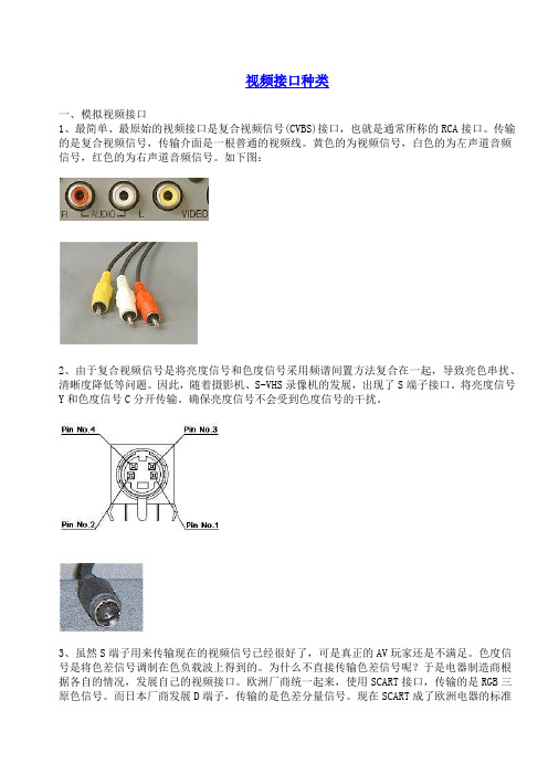
视频接口种类一、模拟视频接口1、最简单、最原始的视频接口是复合视频信号(CVBS)接口,也就是通常所称的RCA接口。
传输的是复合视频信号,传输介面是一根普通的视频线。
黄色的为视频信号,白色的为左声道音频信号,红色的为右声道音频信号。
如下图:2、由于复合视频信号是将亮度信号和色度信号采用频谱间置方法复合在一起,导致亮色串扰、清晰度降低等问题。
因此,随着摄影机、S-VHS录像机的发展,出现了S端子接口。
将亮度信号Y和色度信号C分开传输。
确保亮度信号不会受到色度信号的干扰。
3、虽然S端子用来传输现在的视频信号已经很好了,可是真正的AV玩家还是不满足。
色度信号是将色差信号调制在色负载波上得到的。
为什么不直接传输色差信号呢?于是电器制造商根据各自的情况,发展自己的视频接口。
欧洲厂商统一起来,使用SCART接口,传输的是RGB三原色信号。
而日本厂商发展D端子,传输的是色差分量信号。
现在SCART成了欧洲电器的标准接口,而日本的高档DVD机和电视机都具备D端子。
美国人则延续了使用RCA端子的传统,使用3个RCA端子来传输色差分量信号。
由于美国在数字视听领域的强大势力,3 RCA色差分量数字在欧洲和日本以外的地区成了DVD播放机的标准输出接口。
即使在日本和欧洲,大部分DVD 播放机也具备色差分量接口。
而我国厂商则在较高档的逐行DVD机装备了VGA输出接口。
实际上在DVD机上装备VGA接口在美国是违反版权保护法的,因为现在在VGA接口上还没有版权保护措施,因此不允许使用VGA接口输出高质量的视频信号。
这也就是为什么我们在飞利浦、SONY、松下、先锋等进口机器上看不到VGA接口的原因,非不能也,是不为也。
欧洲的SCART接口:日本的D端子:D端子分以下5种,实际的接口和传输线都完全相同,只是传输的信号格式不同而已:D1: 525i(普通NTSC 525行隔行信号)D2: 525i, 525p(在D1的基础上,增加NTSC 525行逐行信号)D3: 525i, 525p, 1125i(在D2的基础上,增加HDTV 1125行隔行信号)D4: 525i, 525p, 1125i, 750p(在D3的基础上,增加HDTV 750行逐行信号)D5: 525i, 525p, 1125i, 750p, 1125p(在D4的基础上,增加HDTV 1125行逐行信号)注:525i也习惯称480i,525p也习惯称480p,1125i也习惯称1080i,750p也习惯称720p。
STB常用接口介绍

1.RF(Radio Frequency)RF射频端子是最早在电视机上出现的,也是目前家庭有线电视采用的接口模式。
成像原理:将视频信号(CVBS)和音频信号(Audio)相混合编码后,输出然后在显示设备内部进行一系列分离/ 解码的过程输出成像。
传输信号:模拟音视频信号优点:接口简单,成本低,传输距离远(>100m)。
缺点:由于步骤繁琐,且音视频混合编码会互相干扰,所以它的输出质量也是最差的。
我司的RF调制器(21-69CH)也采用此种接口。
2.CVBS(Composite Video Broadcast Signal)复合视频信号,最简单、最原始的视频接口,也就是通常所称的RCA(标准视频输入)接口。
传输的是复合视频信号,传输介面是一根普通的视频线。
黄色的为视频信号,白色的为左声道音频信号,红色的为右声道音频信号。
传输信号:模拟音视频信号优点:传输方便、设备结构简单、成本低,成为目前电视设备上应用最广泛的接口。
缺点:由于A V接口是将亮度信号和色度信号采用频谱间置方法复合在一起的,传输的仍然是一种亮度/色度(Y/C)混合的视频信号,仍然需要显示设备对其进行亮/色分离和色度解码才能成像,所以亮色串扰、清晰度低的问题是没法解决的,一般来说只适合用在低清晰度视频信号上。
3.S-Video(Separate Video)也有人称为Supper Video,二分量视频接口。
它将色度信号C 和亮度信号Y进行分离,再分别以不同的通道进行传输,通常采用标准的4芯(不含音效) 或者扩展的7芯( 含音效)接口。
传输信号:模拟视频信号优点:采用亮色分离,使用独立的传输通道,在很大程度上避免了视频设备内信号串扰而产生的图像失真,极大地提高了图像的清晰度。
S-Video虽不是最好的,但考虑到目前的市场状况和综合成本等其它因素,它还是应用最普遍的视频接口,一般可达1024线。
缺点:虽然实现了亮色分离,但S-Video 仍要将两路色差信号(Cr Cb)混合为一路色度信号C,进行传输然后再在显示设备内解码为Cb 和Cr 进行处理,这样仍会带来一定信号损失而产生失真(这种失真很小,但在严格的广播级视频设备下进行测试时仍能发现) 。
图解各种接口
“视频输出端口介绍(HDMI、DVI、VGA、RGB、分量、S端子、USB接口)”视频输出端口介绍(HDMI、DVI、VGA、RGB、分量、S端子、USB接口)视频输出端口介绍(HDMI、DVI、VGA、RGB、分量、S端子、USB接口)视频输出端口介绍(HDMI、DVI、VGA、RGB、分量、S端子、USB接口)S 端子(S-Video)是应用最普遍的视频接口之一,是一种视频信号专用输出接口。
VGA接口是显卡上输出信号的主流接口,其可与CRT显示器或具备VGA接口的电视机相连,VGA接口本身可以传输VGA、SVGA、XGA等现在所有格式任何分辨率的模拟RGB+HV信号,其输出的信号已可和任何高清接口相貔美。
S端子与VGA,哪个接到电视上看的比较清晰?1RCA (俗称标准视频输入端子/ AV端子)还有一种三基色BNC端子( 或称RGB端子),BNC端子这种是很容易与一般色差端子混淆,三基色RGB端子的情况比分量色差端子要复杂些。
DVI接头有三种,分别是DVI-Digital(DVI-D)、DVI-Analog(DVI-A)跟DVI-Integrated (DVI-I),DVI-Digital (DVI-D)只有支持数字显示的设备、DVI-Analog(DVI-A)只有支持数字显示的设备,DVI-Integrated (DVI-I)则是支持数字显示跟模拟显示。
HDMI接口有什么用_百度知道HDMI接口有什么用 .我的主板上有有个HDMI接口和VGA接口,我装了个独显,上面有TV-OUT,DVI,VGA三个接口,显示器上有DVI和VGA接口,我平时上网用的是独显上的VGA接口连显示器的VGA接口,如果看高清电影是不是还要再连一根线!接主板的HDMI接口和显示器接口?常用视频接口VGA、DVI、AV、S端子、色差分量、HDMI、D...常用视频接口VGA、DVI、AV、S端子、色差分量、HDMI、D端子等各种接口解释。
各种接口图片
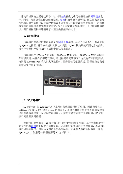
作为局域网的主要连接设备,以太网交换机成为应用普及最快的网络设备之一,同时,也是随着这种快速的发展,交换机的功能不断增强,随之而来则是交换机端口的更新换代以及各种特殊设备连接端口不断的添加到交换机上,这也使得交换机的接口类型变得非常丰富,为了让大家对这些接口有一个比较清晰的认识,我们根据资料特地整理了一篇交换机接口的文章:1、RJ-45接口这种接口就是我们现在最常见的网络设备接口,俗称“水晶头”,专业术语为RJ-45连接器,属于双绞线以太网接口类型。
RJ-45插头只能沿固定方向插入,设有一个塑料弹片与RJ-45插槽卡住以防止脱落。
这种接口在10Base-T以太网、100Base-TX以太网、1000Base-TX以太网中都可以使用,传输介质都是双绞线,不过根据带宽的不同对介质也有不同的要求,特别是1000Base-TX千兆以太网连接时,至少要使用超五类线,要保证稳定高速的话还要使用6类线。
2、SC光纤接口SC光纤接口在100Base-TX以太网时代就已经得到了应用,因此当时称为100Base-FX(F是光纤单词fiber的缩写),不过当时由于性能并不比双绞线突出但是成本却较高,因此没有得到普及,现在业界大力推广千兆网络,SC光纤接口则重新受到重视。
光纤接口类型很多,SC光纤接口主要用于局网交换环境,在一些高性能千兆交换机和路由器上提供了这种接口,它与RJ-45接口看上去很相似,不过SC 接口显得更扁些,其明显区别还是里面的触片,如果是8条细的铜触片,则是RJ-45接口,如果是一根铜柱则是SC光纤接口。
3、FDDI接口FDDI是目前成熟的LAN技术中传输速率最高的一种,具有定时令牌协议的特性,支持多种拓扑结构,传输媒体为光纤。
光纤分布式数据接口(FDDI)是由美国国家标准化组织(ANSI)制定的在光缆上发送数字信号的一组协议。
FDDI 使用双环令牌,传输速率可以达到100Mbps。
CCDI 是 FDDI 的一种变型,它采用双绞铜缆为传输介质,数据传输速率通常为 100Mbps。
视频各种接口详细图解

视频各种接口详细图解很多初级用户在看投影机文章或将投影机与其它设备进行连接时,面对众多的接口总是感到茫然。
其实只要弄明白它们的用途和连/转接方法,在使用时您会觉得其也并非有登天之难。
投影机接口虽没有高档功放上那么多但也不少家用投影机上的常用接口拉近点就看清楚了一、常规视频输入端子做为视频播放设备,投影机上输入端子(端子=接口)的数量远多于输出端子,视频端子的数量也远多于音频端子。
●标准视频输入(RCA)RCA是莲花插座的英文简称,RCA输入输出是最常见的音视频输入和输出接口,也被称AV接口(复合视频接口),通常都是成对的,把视频和音频信号“分开发送”,避免了因为音/视频混合干扰而导致的图像质量下降。
但由于AV接口传输的仍是一种亮度/色度(Y/C)混合的视频信号,仍需显示设备对其进行亮/色分离和色度解码才能成像,这种先混合再分离的过程必然会造成色彩信号的损失,所以其目前主要被用在入门级音视频设备和应用上。
音频转RCA线RCA转接延长头插入示意图白色的是音频接口和黄色的视频接口,使用时只需要将带莲花头的标准AV 线缆与其它输出设备(如放像机、影碟机)上的相应接口连接起来即可。
不要小瞧了RCA,其也有做工不错的高档货S端子标准S端子标准S端子连接线音频复合视频S端子色差常规连接示意图S端子(S-Video)是应用最普遍的视频接口之一,是一种视频信号专用输出接口。
常见的S端子是一个5芯接口,其中两路传输视频亮度信号,两路传输色度信号,一路为公共屏蔽地线,由于省去了图像信号Y与色度信号C的综合、编码、合成以及电视机机内的输入切换、矩阵解码等步骤,可有效防止亮度、色度信号复合输出的相互串扰,提高图像的清晰度。
一般DVD或VCD、TV、PC都具备S端子输出功能,投影机可通过专用的S端子线与这些设备的相应端子连接进行视频输入。
显卡上配置的9针增强S端子,可转接色差S端子转接线欧洲插转色差、S端子和AV与电脑S端子连接需使用专用线,如VIVO线S端子在一些投影机厂家的称呼只中又被称为mini-DIN接口,包含4芯(不带音效输出)、5芯、6芯、7芯、8芯、9芯(能提供6个声道的讯号输出)等不同的产品都在投影机上被使用。
各种HDMI接口的版本区别视频接口全接触高清知识
九大视频接口全接触1 射频不像射频接口那样包含了音频信号,复合视频(Composite)通常采用黄***色的RC A(莲花插座)接头。
“复合”含义是同一信道中传输亮度和色度信号的模拟信号,但电视机如果不能很好的分离这两种信号,就会出现虚影。
3 S端子S端子(S-Video)连接采用Y/C(亮度/色度)分离式输出,使用四芯线传送信号,接口为四针接口。
接口中,两针接地,另外两针分别传输亮度和色度信号。
因为分别传送亮度和色度信号,S端子效果要好于复合视频。
不过S端子的抗干扰能力较弱,所以S端子线的长度最好不要超过7米。
4 色差色差(Component)通常标记为Y/Pb/Pr,用红、绿、蓝三种颜色来标注每条线缆和接口。
绿色线缆(Y),传输亮度信号。
蓝色和红色线缆(Pb和Pr)传输的是颜色差别信号。
色差的效果要好于S端子,因此不少DVD以及高清播放设备上都采用该接口。
如果使用优质的线材和接口,即使采用10米长的线缆,色差线也能传输优秀的画面。
5 VGAVGA(Video Graphics Array)还有一个名称叫D-Sub。
VGA接口共有15针,分成3排,每排5个孔,是显卡上应用最为广泛的接口类型,绝大多数显卡都带有此种接口。
它传输红、绿、蓝模拟信号以及同步信号(水平和垂直信号)。
使用VGA连接设备,线缆长度最好不要超过10米,而且要注意接头是否安装牢固,否则可能引起图像中出现虚影。
6 DVIDVI(Digital Visual Interface)接口与VGA都是电脑中最常用的接口,与VGA不同的是,DVI可以传输数字信号,不用再进过数模转换,所以画面质量非常高。
目前,很多高清电视上也提供了DVI接口。
需要注意的是,DVI接口有多种规范,常见的是DVI-D (Digital)和DVI-I(Intergrated)。
DVI-D只能传输数字信号,大家可以用它来连接显卡和平板电视。
DVI-I则在DVI-D可以和VGA相互转换。
电脑常见的接口大全

电脑常见的接口大全每一台计算机,不管是台式机还是笔记本,里里外外都有很多的接口,你能把它们每一个都认出来而且知道它们的用途吗?通常一些相关的文章介绍起来都缺乏耐心,而且也没有足够的插图之类,更使得大家犯迷糊。
本文旨在综合参考之用,不仅是帮助新人菜鸟,希望也能够对经验丰富的人有所帮助。
通过大量的图片和简单的解释文字,我们将向您介绍在PC上各种各样的插槽、端口、接口,以及通常是什么样的设备来连接在上面。
因此本文对于那些对电脑外接口不太清楚的人会更有帮助一些,而不是一篇电脑连接故障的快速参考书。
PC的部件连接性方面比较让人欣慰的是:不兼容的接口配件等根本就不能连接在一起。
当然也不排除极少的情形出现,还好因此导致硬件损害的事情现在也是非常少见了。
USBUSB(Universal Serial Bus)接口大家可能最熟悉了吧,USB是设计用来连接鼠标、键盘、移动硬盘、数码相机、网络(VoIP的skype之类)、打印机等外围设备的,理论上一个USB主控口可以最大支持127个设备的连接。
USB分为两个标准,USB1.1最大传输速度为12Mbps,USB2.0为480Mbps,这两种标准的接口是完全一样的,也可向下兼容,传输速度的不同取决于电脑主板的USB主控芯片和USB设备的芯片。
USB接口可以带有供电线路,这样USB设备例如移动硬盘等就不用再接一条电源线了(最高500mA 5V电压),现在支持USB接口的手机也可以通过电脑来充电。
USB接口方式有三种:PC上常见的是Type A型,一些USB设备上(一般带有连接线缆)常使用Type B,而Mp3、相机、手机等小型数码设备上通常是mini USB接口。
这条线的左边就是接电脑的Type A型口,右边就是接设备的Type B 型口,这种线常用在打印机、大移动硬盘盒等设备上面。
USB延长线,一般在5米之,如果你嫌电脑的USB接口在后面不方便,可以买一条这样的线把它导出到前侧来。
视频信号发生器操作手册说明书
视频信号发生器操作手册视频信号发生器详情请联系深圳君辉电子郑经理:138****5356K-826X 简易操作手册(不同型号会有些差异)1视频信号发生器操作手册2前言感谢您购买MIK可编程视频信号发生器。
本操作手册为您提供操作方法,让您可以高效使用本设备进行高清电视,投影机,显示器等的开发、生产及检测等。
产品输出信号类型及应用手册< K -8267R 前面板>< K -8267R 后面板>3■ 交流电源-. 断开电源线时,首先关闭信号发生器前部电源开关,然后拔掉电源线。
-. 确保电源线未损坏。
-. 开关电源请使用前面板ON/OFF 开关。
■ 无外部干扰-. 清除液体、易燃物和金属 (磁铁等)。
-. 移开风扇周围物体。
■ 禁止垂直安装-. 请在平滑地方安装信号发生器,切勿垂直安装。
■ 无振动-. 信号发生器为高频高精度设备,强烈振动可能引发故障。
■ 显示器设备与K-826X 连接前-. K-826x 与显示器设备连接时需保持断电。
-. 为避免潜在异常情况及电击,请将两设备间进行屏蔽接地。
-.接地线至■ 当K-826X 与显示器设备断开连接时 -. 关闭电源,断开连接。
-. 断开信号线,然后屏蔽接地线。
■ 前部 C/F Card 的操作-. 关闭电源,然后插入或断开连接。
-. 若电源未关闭时插入或断开连接,则可能造成Flash Card 损坏及数据丢失。
■ 系统稳定之时间设定-. 可以打开电源立即开始设定时间,但建议待5分钟后具体数据稳定后再行设定。
视频信号发生器操作手册1.一般规格1.1 K-826X 系统概要K-826X可编程视频信号发生器是以用户为中心,使其编辑图形操作简单化,输出信号多样化;给予PDP,LCD TV Monitor, TFT-LCD Monitor, HDTV等生产厂家的研发和生产提供视频信号检测的设备,输出信号支持Analog, DVI, HDMI, CVBS,Y/C, YPbPr, D-Terminal, Scart。
各种视频信号格式及端子介绍
各种视频信号格式及端子介绍RF/AV/SVIDEO/YUV/VGA/RGB/RGBS/DVI/HDMI/视频信号是我们接触最多的显示信号,但您并不一定对各种视频信号有所了解。
因为国内用到的视频信号格式和端子非常有限,一般就是复合视频和S端子,稍高级一些的就是色差及VGA。
对于那些经常接触国外电器和二手设备的朋友,就会遇到各种希奇古怪的信号端子,我们也经常接到读者这方面的提问。
请读者注意:我们这里所说的视频信号并不是严格意义上的带宽只有5MHz的视频信号,而是泛指能作为输入输出的显示信号。
本文试图把常用视频信号做一简单叙述,有不全和不对的地方请读者朋友指出。
一、各种视频信号复合视频信号(Video)复合视频信号是我们日常生活中最为常见的视频信号,它在一个传输信号中包含了亮度、色度和同步信号。
由于彩色编码的不同,复合视频又有PAL、NTSV、SECAM制式之分。
复合视频信号本身的带宽只有5MHz(NTSC制式带宽仅4.5MHz),中间又加了彩色副载波信号(NTSC制为3.58MHz,PAL和SECAM制为4.43MHz),正好落在亮度信号带宽之内,占去了一部分亮度信号,又造成亮度和色度的相互干扰,使得复合视频成为最差的视频信号。
复合视频信号一般用RCA插头连接,就是通常说的莲花插头,见图1。
欧洲也用SCART接口,老式的视频设备也有用BNC插头连接。
S视频信号(S-Video)S视频信号俗称S端子信号,它同时传送两路信号:亮度信号Y和色度信号C。
由于将亮度和色度分离,所以图象质量优于复合视频信号,色度对亮度的串扰现象也消失。
由于S视频信号亮度带宽没有改变,色度信号仍须解调,所以其图象质量的提高是有限的,但肯定解决了亮色串扰,消除图象的爬行现象。
S端子用四芯插头,见图2。
欧洲也用SCART插头,老式的视频设备也有用两个BNC插头连接,计算机显卡也有用七芯插头,其外形与S端子一样,只是又包含了复合视频信号。
海信TLM42V68P系列(1672板)主板电路原理图

Low = HP insertHigh = WP disable High = Mute onADIN0ADIN1ADIN2ADIN3ADIN4ADIN5GPIO_20GPIO_21GPIO_22GPIO_23GPIO_24GPIO_25HMDI 0 HPLUG DETECT HMDI 1 HPLUG DETECT HMDI 2 HPLUG DETECT High = WP disable Low = Backlight onPWM0PWM1PWM2PWM3UP30UP31UP33UP34UP35GPIO_0GPIO_1GPIO_2GPIO_3GPIO_4GPIO_5GPIO_6GPIO_7GPIO_8GPIO_9GPIO_10GPIO_11INTAudio MUX select bit 0( DDR1 WITH TERMINATION )Low = Normal power onLVDS RESERVED LVDS RESERVED Hi = LVDS power onBL ON/OFF CONTROL MT82224052 SWITCH FCI FCIAMP_MUTE CONTROL LVDS POWER ON/OFF DIMMING CONTROLGPIO DefinitionGPIO usageMT8222_P1V1 (DDR1)NORMAL POWER ON/OFF Audio MUXVERSION V1.0AMP_SD/FCISCART1 VIDEO OUTPUT SW/FCI SFlash RF TunerHDMIx3Power DistributionDDR1VGAUSBx2Power conversion to 33V FCI FCI FCI FCISYSTEM E2PROM WP LVDS out CVBS x 2S-Video x 1YPbPr x 2Analog AMPSpeaker E2PROMAudio MUXJiu.NiHDMI/VGA EDID E2PROM WP Function defineTI3101D (10Wx2)HeadphoneTDA98854052 x 2Micphone InterfaceGAME GAME GAME GAMESCART FS SCART FS 4052 SWITCHKEYPAD KEYPADSPDIFIN GPIO/BLOCKHISENSE_MT82222008/1/25MICPHOTO RESERVE AOSDATA0AOLRCK AOBCLK AOMCLKUSB1 PWR ENABLE USB1 OC TAGUSB0 OC TAGUSB0 PWR ENABLE 4558Scart x 2DACMCU WT6702POWER1、主板框图、GPIO口说明及电源供电框图ISE NS ETR AI NI NG5V_MPower LDOIf use ddr ,NC FB14If use sdram ,NC FB14Jiu.Ni2008/1/25HISENSE_MT82222、系统电源供电部分电路3、MT8222主芯片及其外围匹配网络部分电路AV33_XTL 3AV122DV102,3AV12_PLL 3AV12_MEMPLL 3AV12_LVDS 3AV33_HDMI 3AV33_LVDS 3AV33_CVBS 3AV33_ADC 3AV12_USB 3AV12_HDMI 3AV33_SIF 3DV333AV33_VGA 3AV33_USB 3+3V32,3,6,7,10,12,13AV33_DAC 3DDRV2,5GND2,3,5,6,7,8,9,10,11,12,13AV12_LVDSPLL 3DDRV_MTK 3Jiu.Ni2008/1/25HISENSE_MT82224、MT8222主芯片旁路电容部分电路NGRDQS0RDQM0RDQM1RDQS13RA[12..0]3RDQS03RDQS13RDQM03RDQM1333333333332,42,3,4,6,7,8,9,10,11,12,13DDR1 DRAM Jiu.Ni2008/1/25HISENSE_MT8222取消5、SDRAM存储器及其外围匹配网络部分电路ISE G3333,83,8333333332,3,4,7,10,12,13233,11,123,133,133,133,113333OSCL03,10,13OSDA03,10,132,3,4,5,7,8,9,10,11,12,132,3,8,11,12,13333+5VS2,7,83232Jiu.Ni2008/1/25HISENSE_MT8222ADC KEYPAD6、E2PROM、复位、串行FLASH、USB接口、触摸按键、遥控接收及指示灯控制等部分电路GHDMIX3Jiu.Ni2008/1/25HISENSE_MT82227、HDMI1/HDMI2/HDMI3接口及外围匹配网络部分电路G333333323,7VGASDA 3VGASCL 3+3V32,3,4,6,7,10,12,1311113,63,631212CVBS/ S-Video / VGA Jiu.Ni2008/1/25HISENSE_MT82228、AV/S端子/VGA接口及外围匹配网络部分电路GYPbPrJiu.Ni2008/1/25HISENSE_MT82229、AV1/YPbPr接口及外围匹配网络部分电路3333GND2,3,4,5,6,7,8,9,11,12,13+5V_TUNER 2OSCL03,6,13OSDA03,6,132,12,13PWM132,3,4,6,7,12,13RF Tuner Jiu.Ni2008/1/25HISENSE_MT822210、高频头及中放处理部分电路U15TUNER_IFISE NG5V_M2,3,4,5,6,7,8,9,10,12,13333333,123,6,123,123,123388999988883,6AudioMUX/SPDIF Jiu.Ni2008/1/25HISENSE_MT822211、音频切换及光纤输出部分电路I33+3V32,3,4,6,7,10,1312V_M2,10,13SCT2_AUR_OUT 8SCT2_AUL_OUT 82,3,4,5,6,7,8,9,10,11,13AVOUT_L 13AVOUT_R 133,113,6,113,113,112,3,6,8,11,13Jiu.Ni2008/1/25HISENSE_MT822212、HDMI数字音频D/A转换及耳机输出部分电路NGJiu.Ni2008/1/25HISENSE_MT822213、液晶屏供电切换、LVDS接口、伴音功放及静音控制部分电路。
HDMI中SCL和SDA两个引脚的作用

HDMI中SCL和SDA两个引脚的作用上一篇/ 下一篇 2011-08-16 18:04:47查看( 1755 ) / 评论( 0 ) / 评分( 0 / 0 )高清晰度多媒体界面(英语:High Definition Multimedia Interface,简称HDMI)Pin Pin定义1 Hot Plug Detect2 Utility3 TMDS Data2+4 TMDS Data2 Shield5 TMDS Data2-6 TMDS Data1+7 TMDS Data1 Shield8 TMDS Data1-9 TMDS Data0+10 TMDS Data0 Shield11 TMDS Data0-12 TMDS Clock+13 TMDS Clock Shield14 TMDS Clock-15 CEC16 DDC/CEC Ground17 SCL18 SDA19 +5V PowerHDMI是被设计来取代较旧的模拟影音传送接口如SCART或RCA等端子的。
它支持各类电视与电脑图像格式,包括SDTV、HDTV视频画面,再加上多声道数字音频。
在传送时,各种视频数据将被HDMI收发芯片以“Transition Minimized Differential Signaling”(TMDS)技术编码成数据分组。
HDMI D Type应用于HDMI1.4版本,总共有19pin, 规格为2.8 mm × 6.4 mm,但脚位定义有所改变。
新的Micro HDMI 接口将比现在19针MINI HDMI版接口小50%左右,可为相机、手机等便携设备带来最高1080p的分辨率支持及最快5GB的传输速度。
Pin Pin定义1 Hot Plug Detect2 Utility3 TMDS Data2+4 TMDS Data2 Shield5 TMDS Data2-6 TMDS Data1+7 TMDS Data1 Shield8 TMDS Data1-9 TMDS Data0+10 TMDS Data0 Shield11 TMDS Data0-12 TMDS Clock+13 TMDS Clock Shield14 TMDS Clock-15 CEC16 DDC/CEC Ground17 SCL18 SDA19 +5V PowerTMDS通道∙传送音频,视频,以及各种辅助数据∙信号编码方式:遵循DVI 1.0规格。
专业音频音乐术语中英文对照
专业音频音乐术语中英文对照专业音频音乐术语中英文对照AF Safety 安全装置,保险装置,保护装置Safeguard by 防护器SALT symmetry air load technique 对称空气负载技术Samba 桑巴Sample 声音信号样品,采样,取样,抽样Sampling 抽样,脉冲调制SAP second audio program 第二套音频节目SAT saturate 饱和效果处理Save 贮存Save 存储,保存Saxophoneb 萨克司管Saxophome 顶馈直线天线SC set clock 置位时钟SC sigmal control 信号控制SC subcarrier 副载波SC system controller 系统控制器SC scan 扫描Scale 音阶,刻度尺标Scale unit 标度单位,分频器Scan 搜索,记录,扫描Scar 激光唱片上的缺陷SCART connector欧洲标准21脚AV接口Scattering 散射Scene 实况,场面SCH search 搜索,寻找Scheme 设计图,原理图SCMS serial copy management system 成套复制管理系统Screw 螺丝钉Scrollback 回找SCH stereochrous 立体声合唱Schmidt trigger 施密特触发器Scintillation 闪烁,调制引起的载频变化SCMS successive copy manage system连续复制管理系统(DAT设备中防止多次转录节目的系统)Scoop 戽斗,收集器Scope 范围,显示器Scoring 音乐录音SCR signal to clutter ratio 信噪比SCR silicon controlled rectifier 晶闸管整流器Scraper 刮声器Screen 屏蔽SD space division 空间分布S-DAT stationary head DAT 固定磁头DAT机SDDS sony dynamic digital sound 索尼动态数字环绕声系统SDI standard data interface 标准数据接口SDLC synchronous data link control 同步数据链控制器SE single end 单端的SE sound effect 音响效果SE storage element 存储元件SE support equipment 支援设备SEA soond effect amplifier 音响效果放大器SEA special effects amplifier 特殊效果放大器Search 搜索,扫描Searcher 扫描器SEC Second 秒,第二SECAM sequential color and memory 调频行轮换彩色制式Section 单元,环节Sectoral horm 扇形号筒Security 保险,加锁SED system effectiveness demonstration 系统效果演示Seek 搜索SEL selector 选择装置,寻线器,转换开关Select 选择Selectivity (收音机)选择性Semi- 半-Semibreve 全音符Semioctave 半个八度音Semit 半音SEN sensor 传感器Send 送出,发送,发射SENS Sensitivity 灵敏度Sense 分辨率Sensor 传感器Sentinel 发射器,传送器SEP standard electronic package 标准电子组件SEP system engineering process 系统工程处理Separator 分离器,分解器Septieme 七倍音SEQ sequencer 音序器,定序器SEQ Stereo equalizer 立体声均衡器Sequence 排序,序列Series 系列,串连Service 维修,服务Servo 伺服机构,随机系统Servo motor 伺服马达SES spatial effect system 立体声空间效果系统Session 跟随自动伴奏Set 调整,设定,装置,定位,接收机Setout 开始,准备Setup 设定,构成,菜单,组合,调整SFC sound field composer 声场合成装置SFL stereo flange 立体声法兰镶边SFS sound field synthesis 声场合成SG signal generator 信号发生器SGL signal 信号S-hall small hall 小型厅堂效果Shake 震动Shape 波形,轮廊Shaper 整形器,脉冲成形Share drum 小军鼓Sharpness 清晰度,鲜明度,锐度Shelving 滤除,滤波处理SHG sub harmonic generator 次(分)谐波发生器Shield 保护,屏蔽Shift 转换,变调,移频,漂移Shock 冲击Short 短的Short gate 短时选通门(混响效果)Shower 指示器,显示器SHUF Shuffle 随机顺序节目播放Shunt 分路,并联SHUTT shuttle 变速搜索,往复SI sneak in 淡入Sibilance 齿音,咝音Sibilant 咝音Sibilation 咝音,高频声畸变SICS sound image control system 声像控制系统Side 边,面,侧面,方面Side chain 旁链SIG signal 声音信号Signature 特征,音乐的调号SIF 伴音中频Silencer 静噪器Silent 静噪调谐Simple tone 纯音Simplex 单工Simulate 模拟的Simultaneous 同步,联立SINAD signal to noise and distortion ratio信号对噪声和失真比Sine wave 正弦波Single 单,单次的,单独的,单碟SIP solo in place 独奏入位SIP standard information package 标准信息包Siren 旋笛Size 尺寸Skew control 扭曲校正,菱形失真器Skip 跳跃,省略SL signal level 信号电平Slap 拍打效果Slap back 山谷回声Slap reverb 山谷混响效果Slate 预定,标记,(录音调音台)标记开关Slave 从属的,从机,从动的Sleep 睡眠定时开关,静止Sleeve(SLE) 接地点,袖端,套Slew rate 瞬态率Sliding tone 滑音Slope 斜率,坡度,跨导Slow 慢速SLP super long play 超长(三倍)时间播放Sliding tone 滑音SLS studio listen 演播室监听SM sequential machine 时序机SM signal meter 信号强度计SM storage mark 存储标志S/M speech/music 语言/音乐S/N signal-to-noise radio 信噪比Small club 小俱乐部效果Smear 曳尾,拖尾,浑浊不清Smear correction 拖尾校正SMF Standard MIDI File 标准SMP sampler 取样器SMPTE society of motion picture television engineers(美国)电影及电视工程师学会S/N signal/noise 信号/噪声,信噪比SND sound 声音,音响,伴音Snake 集体线Snapshot 片段,场景状态设置Snubber 缓冲器,减震器SO sneak out 淡出Socket 插座,插口Soft 软的,柔和的Soft click 柔性箝位Soft knee 软拐点(压限器)Soft-touch 轻触式Software 计算机软件Solo 独唱,独奏Sone 宋(响度单位)Song 乐曲Sound colum 声柱Sound field 声场Sound image 声像Sound intensity 声强Sound shadow region 声影区Sound cousole desk 调音台Source 声源SOS sound on sound 叠加录音SP speaker 扬声器SP speed 速度SP standard-play 标准走带速度录放SPA stereo pan allochthonous 立体声声像漂移Space 间隙,空间效果Spaciousness 空间感ST stereo 立体声,立体STI speech transmission index 语言传输系统Sticks **作杆,安置,卡子Still 静止STM send test massage 发送测试信号STO stand point 位置STO stereo 立体声STO stop 停止STO store 存储,存储器STP shielded twisted pnir 屏蔽双绞线Strike note 击弦音,撞击声String instrument 弦乐器Strip 卸下附属设备,轨道,类别Strobe 选通脉冲,频闪放电管Strong 有力的Structure 装置,结构STU Studio 演播室效果SUB 副,辅助,附加,低音Subgroup 副,(调音台的通道集中控制网络)编组Suboctave次八度Subsonic 次声,超低音Subwoofer 超低音Sum 和,总和,总数SUP Supply 电源Supper 超Super bass 超低音Super over drive 超激励Suppressor 抑制器Support programs 支援程序SUR Surround 环绕声,环绕,包围Sustain 保持,维持SVP surge voltage protector 浪肖电压保护器SW signal wire 信号线SW S-Wite 塞套引线SW switch 开关,切换SW short wave 短波S/W specification of wiring 布线规格Swap 交换,调动(等量齐观),调换Sweep 扫描,曲线Swell 增音器Swing 摆幅,摇摆舞Swishing 飕飕声SX simplex 单工SXE stereo exciter 立体声激励器Symphobass 调谐低音系统Symphonic 交响,谐音SYS Ex system expanding 系统扩展TRIG trigger 触发,触发器,触发脉冲Trim 调整,微调,调谐,削波TRK track 音轨TRK trunk 总线,母线,**线Trouble 故障Trumpet 小号TRS time reference system 时间基准系统TST test 测试TTY teleltypewriter 遥控打印机,电传机Tube 电子管,真空管Tune 调谐,和谐,调音Tuner 调谐器Tunetable (唱盘的)转盘Tunnel reverb 隧道混响效果Tupe 处理模式Turbo distortion 涡轮失真效果Turntable 电唱盘,转台TV television 电视Tweeter 高音扬声器·Twin channel 双通道Two complement 补码Two way mode 双面轮流放音模式(录音机)TX transmit 发送,发射TX transmitter 发射机TYP trpe 类型Typical 标准的,典型的TRIG trigger 触发触发器,触发脉冲Trim 调整,微调,调谐,削波TRK track 音轨TRK trunk 总线,母线,**线Trouble 故障Trumpet 小号TRS time reference system 时间基准系统TST test 测试TTY teletypewriter 遥控打印机,电传机Tube 电子管,真空管Tune 调谐,和谐,调音Tuner 调谐器Tunetable (唱盘的)转盘Tunnel reverb 隧道混响效果Tupe 处理模式Turbo distortion 涡轮失真效果Turntable 电唱盘,转台TV television 电视Tweeter 高音扬声器Twin channel 双通道Two complement 补码Two way mode 双面轮流放音模式(录音机)TX transmit 发送,发射TX transmitter 发射机TYP type 类型Typical 标准的,典型的T talk 呼叫,联络Tab 防误抹挡片TACH tachometer 测速器TADI time assigument digital tnterpolation 时分数据插空(技术)Tag 电缆插头Take 实录Takeoff 取出Takeover 恢复,话音叠入,商议Talkback 对讲,联络Tally 播出,提示,插入Tap 电流输出,节拍Tape 带,磁带Tango 探戈TB talkback 对讲回送TB terminal board 接线端子子板TB time base 时基TBC time base corrector 时基校正器TBK tallback 对讲TC telecine 电影电视机TC time code 时间码TC transmitter-tunning circuit 发射机调谐电路TC trim coil 微调线圈TCC tripl concentric cable 三芯同轴电缆TDE time domain equalizer 时域等化器TECH technique 技术,技能,技巧TED television disk 电视唱片TEL telescopic 拉杆天线TEMP temperature 温度Temp 节奏TEMOP temporary 中间(工作)单元TEMPO Tempo 节奏,连接,速度Terminal 终端,接线柱,引线,接头T entelometer 张力表TER termination 终端Test 测试,试验,检验THD total harmonic distortion 总谐波失真Theater 剧场效果,现场Thermal noise 热噪声Thick 沈重,厚重度Thin 单薄声音Thinness 薄(打击乐)THR THRESH threshold 阈值,阈,门限Thresh thrash 多次反复Three dimension 3D音响,三维立体声音响系统Throat 高音号角的喉THRU through 通过,过桥,直接转送Trump 键击噪声,低频噪声,开机砰声Thrust 插入,强行加入THX tom holman"s eXpriment 汤·霍尔曼实验,家庭影院TItemperatun indicator 温度指示器TIE terminal interface exchange 终端接口交换Tie 连接符号,馈线,通信Tierce 第三音,五倍音Tight 硬,紧,硬朗TIM transient intermodulation 瞬态互调失真Timber 音质,音色Timbre 声部Time 时间,倍,次,定时的Timer 定时器,计时器Tininess 单薄Tint 色调TIP terminal interface processor 终端接口处理机Tip 头端,热端Title 标题,字幕TK track 音轨TL track loss 轨迹丢失TLE trunk line equipment **线设备TM trade mark 注册商标TMS transmission mesurement set 电平表TMT transmit 发送TN tuning unit 调谐装置TOC 节目目录Tone 音调,声调,纯音Tone burst 猝发音Tone color 音色Tone quality 音色,音品Tonic 律音Top 最高TOS tape operating system 磁带**作系统Total 总,总共Total tune 整体协调,总调谐Touch 触,压,按Touch sens 键盘乐器指触的触感TPD turnout piece delay 分支延时TR tape recorder 磁带录音机TR telerecording 电视屏幕录像TR tracking 跟踪TR transfer 传输,转移TR trick 特技效果Track 曲目号,磁迹,音轨Tracking 寻迹,跟踪,统调Tracking monitor 调校监听Trad 陷波器,带阻滤波器Tramp 三通道功放系统Transfer 转印,转接Transformer 变压器Transpose 转调,变换器,移调Transport 运行,发送Transient 瞬态Transient distortion 瞬态失真Transient response 瞬态反应Transmit 发射Transistor 晶体管,三极管Transponder 转调器,变换器Transposer 变调器Transversal equalizers 横向均衡器Treble 高音,三倍的,三重的Tremold tremor 颤音Tremolo 震音Tremor 颤音,振音装置Triamp 三路电子分音Trick 特技Trig 修饰Spatializer 声场定位技术SPD speed 调制速度SPDIF sony/philips digital interface 索尼/飞利浦数字接口SPE speaker 扬声器,音箱Special 临时(装置),特设的Specificatin 性能Spectrum 音域,频谱Speech 语言,语音Speed 速度,调制速度。
音视频接口介绍

支持 HDCP, Blue-ray Disc ,
CEC,ARC,3D 等功能,
2021/10/10
音视频接口介绍
HDMI 功能的测试
6
HDCP功能 -----HDCP全文为High-bandwidth Digital Content Protection
10
HDMI 线及接口
HDMI 线长目前有:1.5米、 1米 、2米、 3米、 5米、 8米、10米、12米 15米 。 HDMI 1.4 接口有:HDMI (A型接口)、MINI HDMI (C型接口)、MICRO HDMI (D型接口)
2021/10/10
音视频测试介绍
音频测试注意事项
11
机顶盒的声音输出分两种类型: 1.模拟声音输出
2021/10/10
音视频测试介绍
视频测试注意事项
12
机顶盒的视频输出分以下几种类型:
1.标清信号输出
CVBS/SCART 接口输出 PAL,NTSC,Secam 三种大的类型,根据声音
的调制制式不同,PAL制式还分为PAL-I, PAL-B/G, PAL-D/K,PAL-
M,PAL-N
说明:有时有些电视对这种声音制式识别做法不同,会把PAL-M识别为
声音信号还要另外接红、白 音频线
2021/10/10
音视频接口介绍
标清的音视频接口(数字信号)
5
1.HDMI接口:(High
Definition Multimedia Interface,HDMI)是一种数 字化视频/音频接口技术,是 适合影像传输的专用型数字 化接口,其可同时传送音频 和影音信号,最高数据传输 速度为 5Gbps。同时无需在 信号传送前进行数/模或者模/ 数转换。HDMI可搭配宽带数 字内容保护(HDCP),以 防止具有著作权的影音内容 遭到未经授权的复制。
- 1、下载文档前请自行甄别文档内容的完整性,平台不提供额外的编辑、内容补充、找答案等附加服务。
- 2、"仅部分预览"的文档,不可在线预览部分如存在完整性等问题,可反馈申请退款(可完整预览的文档不适用该条件!)。
- 3、如文档侵犯您的权益,请联系客服反馈,我们会尽快为您处理(人工客服工作时间:9:00-18:30)。
SCART arrangement 1 Pin 1 2 3 4 5 6 7 8 9 10 11 12 13 14 15 16 17 18 19 20 21 Signal Audio output B (right) Audio input B (right) Audio output A (left) Ground (audio) Ground (blue) Audio input A (left) Blue input Function select (AV control) Ground (green) Comms data 2 Green input Comms data 1 Ground (red) Ground (blanking) Red input RGB switching control Ground (video input & output) Ground (RGB switching control) Video output (composite) Video input (composite) Common ground (shield) Signal level 0.5V rms 0.5V rms 0.5V rms GND_A GND_S 0.5V rms 0.7V Impedance <1kohm >10kohm <1kohm >10kohm 75ohmsHigh (9.5-12V) - AV mode / Low (0-2V) - TV >10kohm mode GND_S XXX 0.7V XXX GND_S GND 0.7V High (1-3V) - RGB / Low (0-0.4V) Composite GND_V GND 1V including sync 1V including sync GND ???? 75ohms ???? 75ohms 75ohms 75ohms 75ohms -SCART arrangement 2 Pin 1 2 3 4 5 6 7 8 9 10 11 12 13 14 15 16 17 18 19 20 21 Signal Audio output B (right) Audio input B (right) Audio output A (left) Ground (audio) Ground Audio input A (left) Function select (AV control) Ground Comms data 2 Comms data 1 Ground (chrominance) Ground (blanking) Chrominance input Ground (video input & output) (luminance ground) Video output (composite) Luminance input Common ground (shield) Signal level 0.5V rms 0.5V rms 0.5V rms GND_A GND_S 0.5V rms Impedance <1kohm >10kohm <1kohm >10kohm -High (9.5-12V) - AV mode / Low (0-2V) - TV >10kohm mode xxx xxx 0.3V 1V including sync 1V including sync ???? ???? 75ohms 75ohms 75ohmsSCART connector detailsScart ConnectorThe Scart (Syndicat des Constructeurs d'Appareils Radiorécepteurs et Téléviseurs) connector is used for combined audio and video connections. The connector is also known as Pertitel connector or Euroconnector. A formal description is given in the CENELEC EN 50 049-1:1989 standard or in the IEC 933-1 standard. Different pin-configurations exist. Which confirations are available depends on the video device used. Sometimes one can choose the configuration (like composite or S-video) by changing a software setting. Two status signals define (partly) which video signals are active. A video device can use these status signals to automatically switch between internal or external audio/video signals.Male front viewRGB ConnectionOutput connector 1 Audio right out 3 Audio left (or mono) out 4 Audio return 7 Blue out 5 Blue return 11 Green out 9 Green return 15 Red out 13 Red return 16 RGB status out 14 RGB status return Input connector 2 Audio right in 6 Audio left (or mono) in 4 Audio return 7 Blue in 5 Blue return 11 Green in 9 Green return 15 Red in 13 Red return 16 RGB status in 14 RGB status return19 Sync (composite video) out 20 Sync (composite video) in 17 Sync return 21 Shield 18 Sync return 21 ShieldS-Video ConnectionOutput connector 1 Audio right out Input connector 2 Audio right in3 Audio left (or mono) out 6 Audio left (or mono) in 4 Audio return 15 Chrominance out 13 Chrominance return 8 Video status out 19 Luminance out 17 Luminance return 21 Shield 4 Audio return 15 Chrominance in 13 Chrominance return 8 Video status in 20 Luminance in 18 Luminance return 21 ShieldComposite Video ConnectionOutput connector 1 Audio right out Input connector 2 Audio right in3 Audio left (or mono) out 6 Audio left (or mono) in 4 Audio return 8 Video status out 19 Composite video out 4 Audio return 8 Video status in 20 Composite video in17 Composite video return 18 Composite video return 21 Shield 21 Shield(Composite) Decoder ConnectionReceiver connector 1 Audio right out 2 Audio right in Decoder connector 2 Audio right in 1 Audio right out3 Audio left out 6 Audio left in 4 Audio return 8 Video status in 19 Baseband out (scrambled) 17 Baseband out return6 Audio left in 3 Audio left out 4 Audio return 8 Video status out 20 Baseband in 18 Baseband in return20 Composite video in (unscrambled) 19 Composite video out 18 Composite video in return 21 Shield 17 Composite video out return 21 ShieldEasyLink Connection (additional)Television connector Video recorder connector 10 I/O Control Bus 10 I/O Control Bus EasyLink enables bi-directional communication between a television set and a video recorder. This way a video recorder can, for example, copy the channel settings of the television set. Who knows the details?Signal LevelsSignal Red, green, blue Sync Composite video Chrominance Luminance MAC Audio in Audio out Video status AC level Peak to blanking: 0...0.7 V ±3 dB 0...2 V DC level Impedance 75 Ohm 75 Ohm 75 Ohm 75 Ohm 75 Ohm 75 Ohm >=10 kOhm <=1 kOhmPeak to peak: 0...0.3 V -3 dB...+10 dB 0...2 V White to sync: 0...1.0 V ±3 dB 0...0.3 V -3 dB...+10 dB 0...1.0 V ±3 dB Black to white: 0...1.0 V ±3 dB 0.2...2.0 V (nominal: 0.5 V) Nominal: 0.5 V (maximum: 2.0 V) 0...2 V 0...2 V 0...2 V 0...2 VLow data rate communication: 0.0...2.0 Internal: 0.0...2.0 V In: ZR>=10 kOhm V External (16:9): 4.5...7.0 ZC<=2 nF(e.g. remote control; Easylink)V External (4:3): 9.5...12.0 V Internal: 0.0...0.4 V External: 1.0...3.0 VOut: ZR<=1 kOhmRGB status75 OhmBack to Engineering; Sound & Vision.[eprebel@knoware.nl] Eric-Paul Rebel 1996-10-01back to hardware indexVideo connectionsAmiga Commodore Hercules Mac S550 Scart SGI VGAOn this page I collect my documentation on video connectors. Most information was found by own measurement and fiddling around with computer and video equipment, some data was adapted from other sources.AmigaI found the following 8-pin-DIN input connector on an old Amiga-monitor. The same connector can also be found on Commodore monitors.1 2345 6 ?78nc red green blueH sync V syncCommodoreCommodore made many different monitors. The ones I found were quite similiar to the above mentioned Amiga monitor. Here is some more info about the various 1084 models.HerculesThis video adapter can be found in ancient 8088, 8086 and 80286 machines, it uses a 9 pin D-subminiature connector. On monochrome systems color-pins 3, 4 and 5 are not connected.1 2 3456789red green blue intensity video H sync V syncEncountered 2 different kinds of Hercules systems which are mutually incompatible: 50 Hz and 60 Hz types. MeasuredMS-DOS computer H sync Tulip PhilipsV sync18.41 kHz 50.00 Hz 21.06 kHz 61.00 Hzfrequencies of two systems: I never succeeded in properly connecting these monitors to other systems (like TV, composite-video, or Apple Macintosh computers). Maybe I have not tried every possibility, but it seems like Hercules monitors are very critical regarding horizontal and vertical frequencies.MacintoshMacintosh monitors can easily be attached to other computers. And macintosh computers can easily be connected to non-Apple monitors. You probably have to experiment a little with the sync-signals, but at least you have to know about the Mac's sense-pins. At boot-time, the Mac looks at these sense-pins and initializes its video-hardware accordingly. By changing the sense-wires, you can easily fool your Mac.1 red Code Sense pins 1 2 3 4 5 6 7 8 9 10 11 12 13 14 15 16 none23456 green7 89 1011 sync12 Vsync13 14 blue15red Csync S0 greenS1 NC blue S2NC HsyncTypeResolution Vsync Hsync Bandwidth [H x V] [Hz] [kHz] [MHz] 66.7 35.0 30.2413" B&W, RGB, 12" B&W 640 x 480 12" RGB 15" B&W portrait 15" RGB portrait 16" RGB 19" RGB 21" B&W 21" RGB NTSC NTSC interleave PAL PAL interleave VGA SVGA 13" multiple scan 13" multiple scan 512 x 384 640 x 870 640 x 870 832 x 62460.15 24.48 15.667 75 75 75 68.9 68.9 49.7 57.28 57.28 57.281024 x 768 75 1152 x 870 75 1152 x 870 75 512 x 384 512 x 384 640 x 480 640 x 480 640 x 480 800 x 600 640 x 480 832 x 624 640 x 480 832 x 624 60 60 50 50 60 56 66.7 75 66.7 7560.24 80 68.7 68.7 15.7 15.7 100 100 12.27 12.2715.625 14.75 15.625 14.75 31.47 25.175 35.16 36.0 35.0 49.7 35.0 49.7 30.24 57.28 30.24 57.281024 x 768 75 640 x 480 832 x 624 1024 x 768 1152 x 870 66.7 75 75 7560.24 80 35.0 49.7 60.24 68.7 30.24 57.28 80 1001721" multiple scanRoland S550 samplerI found the following 8-pin-DIN video output connector on the Roland S550 sampler. It looks very much like the Amiga/Commodore-video connector, and the plug mechanically fits. However, notice different pin numbers are used!1 +5 V output2 345678nc H sync V sync red green blueScart interfaceAlso known as Peritel, this standard provides a cheap multi-signal connector to domestic TVs and other video equipment. Arrangement 1 was the original and allows for composite video input/output, RGB inputs and stereo audio. Arrangement 2 was added to take S-Video (S-VHS and Hi-8) inputs. This made pin 15 chrominance and pin 20 luminance. A recent addition is a ternary level on pin 8 to signal a VCR in wide-screen mode. Most new TV sets have 2 SCART sockets on their rear. One is usually to arrangement 1 and the other to arrangement 2, but with pin 20 switchable from composite to S-Video luminance. The first can switch from a composite input to RGB input. The second can switch from a composite input to an S-Video input, pin 20 being either composite in or luminance in. Usually the second socket outputs a selectable composite signal on pin 19. That is selectable from off-air, SCART 1, and if they exist front mounted input sockets for a camcorder. The philosophy seems to be that you connect your satellite receiver or laser disc to socket 1, giving RGB capability. Your video recorder would go on socket 2, and can be S-Video. The video recorder's AUX input can then be fed with whatever you select on the TV. The front mounted sockets for a camcorder are usually phonos for composite video, stereo or mono audio and an S-Video mini-DIN.SCART arrangement 1 Pin Signal Signal level Impedance Pin SignalSCART arrangement 2 Signal levelImpedanc1Audio output B (right) Audio input B (right) Audio output A (left) (audio) (blue) Audio input A (left) Blue input0.5V rms<1 k1Audio output B (right) Audio input B (right) Audio output A (left) (audio)0.5V rms<1 k20.5V rms>10 k20.5V rms>10 k3 4 5 6 70.5V rms 0.5V rms 0.7V<1 k >10 k 75 >10 k ???? 75 ???? 75 75 -3 4 5 6 7 8 9 10 11 12 13 14 15 16 170.5V rms -<1 k >10 k >10 k ???? ???? 75 -Audio input A (left) -0.5V rms -Function H (9.5-12V): AV mode 8 select M (5-8V): Wide-screen (AV control) L (0-2V): TV mode 9 10 (green) Comms data 2 ???? 0.7V ???? 0.7VFunction H (9.5-12V): AV mode select M (5-8V): Wide-screen (AV control) L (0-2V): TV mode Comms data 2 Comms data 1 ???? ???? (blanking) Chrominance input (video in & out) 0.3V -11 Green input 12 13 14 15 16 17 Comms data 1 (red) (blanking) Red inputRGB switch H (1-3V): RGB control L (0-0.4V): Composite (video in & out) (RGB switch control) -18--18--Video 19 output (composite) 20 Video input1V including sync 1V including sync75 7519 20Video output (composite) Luminance1V including sync 1V including sync75 75(composite) input21 Common(shield)- -21Common(shield)- -It is quite easy to connect an Apple macintosh to a TV or NTSC/PAL-monitor without any additional electronics. I did it bybooting my Mac in video mode 10. The Mac is capable of generating a composite sync signal.In case you have no Mac, Tomi Engdahl (e-mail Tomi.Engdahl@iki.fi) developed a nice simple circuit that converts twoseparate Vsync and Hsync signals to a single Csync signal.Silicon GraphicsI did not find any seperate sync-signals (Vsync, Hsync, Csync) on my Indy-monitor-cable.At monitor side there seem to be sense-wires. I compared a 17 inch with a 20 inch monitor.Pins 3, 4, 5, 9 and 10 do not seem to be important.SGImonitor1 (black)2 (brown)6 (white) 7 (grey)8(orange)17 inchnotconnected20 inchnotconnectedWith horizontal sync-frequencies below 60 kHz or so, the screen stays black.I succeeded to drive SGI monitors with an Apple Macintosh Quadra 650 booted in video mode 7 (1024x768 pixels). Othervideo modes (like low resolution 640x480) appear to fail: SGI monitor plays funny high frequency-tunes but screen staysblack.VGAThis connector is found on most Intel-PC's. It's quite easy to feed VGA-monitors with Macintosh-signals (or the other wayaround: attach a Mac-monitor to an Intel-PC). Most modern VGA-monitors are quite tolerant regarding vertical- andhorizontal-sync frequencies.1234,56,7,8910,1112131415red green blue video nc nc H sync V sync ncOn some VGA-monitors (and computers) pin 12 and 15 may be used for power-management.。
