FCO 66 Zr (500)(2) - 副本
FC-6R光纤切割机使用说明书

3. Operating proceduresthe fiber coating (e.g. if the cleave length is 16mm) at the 16mm mark on the ruler.Blade carriageLid of single fiber adapterlid of the single fiber adapter. The blade carriage should be in the forward position.OME1126010COptical Fiber CleaverFC-6ROperation ManualThis product has been designed and manufactured to assure personal safety. Improper use can result in bodily injury and serious damage to the fiber cleaver. Please read and observe all warnings instructions given in this operation manual.1. Do not disassemble or lubricate any parts of the cleaver. Doing so can cause serious damage to the cleaver.2. The FC-6R is a precision tool. Do not impact the cleaver by hitting or dropping it. Doing so can cause personal injury and loss of cleaving performance.3. Glass fiber fragments are extremely sharp. Handle with care. Wear safety glasses at all times during cleaving operation for protection from glass fibers.4. Dispose of glass fiber fragments properly.5. The blade of the cleaver is extremely sharp. Do not touch it with bare hands.6. Do not impact the top clamp lever and switching lever. Doing so can cause damage to the levers and loss of cleaving performance.7. Do not attempt to push further the blade carriage which has been in the rear of the cleaver. Doing so can cause loss of cleaving capability and performance. 8. If the cleaver is damaged or a problem occurs, please contact our service department.SpecificationStandard packageOptional accessories / ConsumablesIMPORTANT SAFETY PRECAUTIONSCautionFC-6RS / FC-6RS-CCladding Diameter 125μmFiber CountCoating Diameter Single fiber (0.25 & 0.9mm)Cleave length 5~20mm (0.25mm), 10~20mm (0.9mm) Cleaving position24 positionsBlade rotation function Fixed / Automatic rotation/ Manual rotation Dimensions FC-6RS: 63(W)x77(D)x63(H)mm FC-6RS-C: 100(W)x81(D)x63(H)mm WeightFC-6RS: Approx. 380g FC-6RS-C: Approx. 420gFC-6RM / FC-6RM-CCladding Diameter 125μmFiber CountCoating Diameter Single fiber (0.25 & 0.9mm) Up to 12-fiber ribbon Cleave length 10mmCleaving position24 positionsBlade rotation function Fixed / Automatic rotation / Manual rotation Dimensions FC-6RM: 63(W)x77(D)x63(H)mm FC-6RM-C: 100(W)x81(D)x63(H)mm WeightFC-6RM: Approx. 380g FC-6RM-C: Approx. 420gFC-6RS FC-6RS-CFiber off-cut collector: CU-FC6RFC-6RM FC-6RM-CSingle fiber adapter: AP-FC6MFiber off-cut collector: CU-FC6RFC-6RS FC-6RS-C FC-6RM FC-6RM-C Optical Fiber Cleaver FC-6R 1 pc 1 pc 1 pc 1 pc Carrying case 1 pc 1 pc 1 pc 1 pc Operation Manual1 pc1 pc1 pc1 pcThis symbol indicates explanations about dangerous matters. If users ignore this symbol and handle the cleaver the wrong way, bodily injury anddamage to the cleaver could result.< Single fiber adapter AP-FC6M >Groove for 0.25mm fiberGroove for 0.9mm fiber < Fiber cleaver FC-6RS(-C)/6RM(-C) >AnvilTop clamp leverBlade carriageBladereceptacleClampSwitching lever (Blade rotation)Switching pin(Rear view)Blade rotation mechanismSingle fiber adapterAP-FC6M1The blade carriage should be in the forward position.2: Place the fiber holder in the cleaver. Place the edge of the fiber holder against the edge of the fiber holder receptacle.3: Lower the top clamp lever. Slide the blade carriage to the rear of the cleaver. The fiber will be cleaved.4: Open the top clamp lever. Remove the fiber holder from the cleaver. Lift the off-cut and dispose it properly. (The FC-6RM-C automatically collects an off-cut in the off-cut collector.)Blade carriage4: Lower the top clamp lever. Slide the blade carriage to the rear of the cleaver. The fiber will be cleaved.5: Open the top clamp lever. Then open the lid of the single fiber adapter and lift the newly cleaved fiber. Lift the off-cut and dispose it properly. (The FC-6RS-C automatically collects an off-cut in the off-cut collector.)Fiber coatingBare fiberCleave length Switching of blade rotating operations<Blade rotating operations>Blade rotating operation can be set by bringing the switching pin to a given position.Blade is not rotated.Blade is rotated by approx. 15° with each cleave.The blade is fixed and not rotated.If a certain area of the blade cannot cleave fiber, rotate the blade with “Automatic rotation” or “Manual rotation” option, referring to the next sections.Fixed (Default setting)0 Automatic rotationR 1: As illustrated in the figure below, pull the switching lever to the right and turnFixedAutomatic rotationManual rotationSwitching leverSwitchingpin(Continued to page 3.)3: Close the lid of the single fiber adapter.Switchinglever Switchingpin2Ensure that the blade carriage is completely pushed to therear of the cleaver. Otherwise the blade is not rotated.2: After sliding the blade carriage to make a cleave, push it further to the rear of the cleaver. The bladeEnsure that the blade carriage is completely pushed to the rear of the cleaver. Otherwise the blade is not rotated.Manual rotation1 2: After sliding the blade carriage to make a cleave, push it further to the rear of the cleaver. The blade is automatically rotated by approx. 1: As illustrated in the figure below, pull the switching lever to the right andThe blade is rotated by 1/24 turn (approx. 15°) once. Afterthe rotation, blade rotating operation returns to [ Fixed].0 CautionCaution4. MaintenanceCleaningTo keep excellent cleaving quality, cleaning must be performed after use. Clean the blade edge, the rubber pad of the clamp and the anvil with a cotton ▪ Dust on the blade edge or the clamp might cause loss of cleavingperformance or poor quality of fiber end face. ▪ Do not clean them with any other kind of chemicals.▪ If the top clamp lever is closed leaving an off-cut fiber on the clamp, the rubber pad of the clamp will have a trace of the fiber, causing loss of cleaving performance or poor quality of fiber end face.Clean the fiber holder receptacle and the grooves of the single fiber adapter, too.CautionIf the problem still persists, please contact our service department. If the cleaving problem occurs, the followings are possible causes. (A) The fiber is placed obliquely in the cleaver.↓ Make sure that the fiber is placed straight in the cleaver. (B) The blade height is too high. ↓ Adjust the blade height.(C) Dust or dirt remains on the clamp. ↓ Clean the clamp.(D) Dust or dirt remains on the blade ↓ Clean the blade.(E) Dust or dirt remains on the fiber.↓ Remove the fiber coating and clean the bare fiber again. Poor cleave angle Lip CrackGoodTroubleshootingSwitching leverSwitchingpin3: When the blade carriage is slid back to the front, the switching pin manually.) Thereafter the blade is fixed.(Continued to step 3.)The blade carriage is slid to cleave fiber.The blade carriage is pushed further to the rear of the cleaver.The blade carriage is slid to cleave fiber.The blade carriage is pushed further to the rear of the cleaver.3Maintenance and repair serviceIf the blade is chipped and cannot cleave fiber, rotate the blade in “Manual rotation” and use the cleaver avoiding thechipped area of the blade. For rotating operation, please refer to “Switching of blade rotating operations.”CautionDo not remove the pin which holds the blade and cleaver body. Do not remove the blade rotating mechanism either.The blade will not rotate or the blade height will change, causing loss of cleaving performance.CautionThe FC-6R must be time for maintenance after 1 year of use or when it cannot cleave fiber. (You will be charged for bladereplacement.) Please return it to our service department when the time for maintenance comes.Caution5. Fiber off-cut collectorInstalling off-cut collector1: Open the top clamp lever fully.2: Put the lever pin into the pin hole of the cleaver< Fiber off-cut collector CU-FC6R >FrontLever pinPut the lever pin into the pin hole of the cleaver.3: Ensure that the lever pin and hook fit the cleaver properly.<Top view>(c) 2011 SUMITOMO ELECTRIC INDUSTRIES, LTD.4: Align the screw holes on the cleaver with the screw holes on the off-cut collector.5: Tighten the 3 setscrews. Optimum torque: Approx. 40cNm6: Completed.Tokyo (JAPAN)Sumitomo Electric Industries, Ltd. (Global Business Dept.)Akasaka Center Building, 1-3-13, Motoakasaka, Minato-ku, Tokyo 107-8468, JAPANTel: +81 (0)3 6406 2666/sumitomo-electric-splicersNorth Carolina (U.S.A)Sumitomo Electric Lightwave Corp. 201 South Rogers Lane, Suite 100 Raleigh, NC27610 U.S.A Toll Free No. 800 358 7378 Tel: +1 919 541 8100London (U.K)Sumitomo Electric Europe Ltd.220 Centennial Park, Centennial Avenue, Elstree, Herts, WD6 3SL, U.K. Tel: +44 (0)20 8953 8118 Hong Kong (China)Sumitomo Electric Asia, Ltd. Tel: +852 2576 0080 /Bangkok (Thailand)Sumitomo Electric (Thailand) Limited Tel: +66 (0)2 260 7231 to 5 /SingaporeSumitomo Electric Asia Pacific Pte. Ltd. Tel: +65 6261 3388.sg/Emptying off-cut collectorOff-cut bin1: Remove the off-cut bin from the off-cut collector and dispose of the off-cuts in a proper way.Notice on Sumitomo genuine productsPlease be very cautious of copy products that pretend Sumitomo genuineproducts.The security hologram is a key to identifying Sumitomo genuine products.Caution<Example: FC-6RS >4Dubai (U.A.E.)Middle East office Tel: +971 4 701 7338Gurgaon (India)SEI Trading India Pvt. Ltd. (SETI) Tel: +91 124 4577 470Manila (Philippines)SEI (PHILIPPINES) INCORPORATED Tel: +63 2 811 2755/2756。
APC APC500 03-2019 v1.0 产品说明书

巖䔘♏䙫 WAN ⟇˛ 5
4. ὦ䔏䶙巖䷁⯮㜓䔉⒨凮わ䙫曢免怊㎌˛
6
5. 媲╆⊼㿶妤♏Ə✏䶙✧⇾弟⅌㜓䔉⒨䙫溿婴 IP ✗✧ 192.168.2.1˛
㨢㔀濕疋方値䕂 IP ◮◾⺃曆⍊㗪䏠⍿⋊◦Ჾỉ⨎⚝Ʋ廰Ჾ㨣奨 㓌濕妉⊁䀥 ㎋Ḛㄉ⁈Ʋ
庙Ჾ㨣媲㓌媵⊀䀥ḽ䏦ㄉ⁊˛
18
III.䜪ᶴ㙴婼
III-1. ❿㙴⩇垃 㜓Ẏ⒨昫嵇⢨㞝垡ḄƏ僤宐わ⯭⅝⭰墬ṵ⢀⢨˛
⩇垃❿㙴噸᳛ℋ濕媵 ⫄ᵥ⍿ⵓ徦䕂㤟侴俘♩䢹攢˛
4. 寞ℯ䡕宋⹝㟮䤡⥤わペ奨✏⢀杉撢垡Ḅ⬻䙫ἴ何Ə撢⬻⏵⯭⋬墬Ⅼ昫䙫
⢨嘵墬⅌Əⅴ⯭憸ⱅ垡Ḅ擨⅌⢨嘵(垡Ḅ寞ᷴ奨⭳⅏擨⅌Ə寞䕀ᷧ⯶㮜䩡 旛)˛
20
COPYRIGHT Copyright ¤ Edimax Technology Co., Ltd. all rights reserved. No part of this publication may be reproduced, transmitted, transcribed, stored in a retrieval system, or translated into any language or computer language, in any form or by any means, electronic, mechanical, magnetic, optical, chemical, manual or otherwise, without the prior written permission from Edimax Technology Co., Ltd.
17
15. 寞わ巆䜧䔢杉㋮䤡⭳ㇷ㭌檋 1-6Ə㛧⏵䂠忰“Finish”Ọ⬿㈧㛰宥⮁˛
斯普雷克斯鞋公司电子目录-过载保护设备产品特性概述说明书

B1.1visit /ecatalog for pricing and the most up to date informationBO v e r l o a d R e l a y sProduct Feature Overview➊ You can also configure CEP9 devices using an optional expansion operator diagnostic station.Choices inOverload RelaysProtecting your investment is critical to keeping your operations up and running. Prevent unwanted down time by choos-ing the right protection for your motor controls. Sprecher + Schuh is proud to offer several options in motor protection. From simple single purpose devices, to varying degrees of selection options and complete factory automation and commu-nication, selecting the right protection is vital to ensuring motor life and longevity. Sprecher + Schuh is here to help protectyour investment.CT7N/CT8Thermal BimetallicKey Features:• Ambient temperature compensation • Rated for DC and variable frequent drive applications up to 400 Hz • Optional remote reset solenoid and external reset accessoriesCEP7 Solid StateKey Features:• Current measurement based protection • Low energy consumption• Side-mount expansion modules provide adjustable levels of protection and commu-nicationCEP9Advanced ElectronicKey Features:• Provides critical motor protection functions • Communication and diagnostics provide detailed logs and control from relay to motor • Can simplify control architecture3r d G e n C E P 7 O v e r l o a d sB1.2visit /ecatalog for pricing and the most up to date informationCEP7 Solid State Overload RelaysThe Third GenerationAdvanced solid state motor protectionThe CEP7-1__ relay provides the follow-ing features:• Electronic overload detection • Simple configuration • Selectable trip class • Adjustable trip current• Integration with CA7/CAN7 contactors• Test and reset buttons• Auto (CEP7-1EF only)/manual resetselection• RMS current sensing (50/60 Hz)• External current transformer configu-rations • Single- and Three-phase compatibility within the same unit • Direct and pass-through mounting options The CEP7-1__ relay lets you connectaccessory modules, some of which inter-face through the front-mounted com-munication port. Accessories include:• Ground fault/jam protection module(CEP7-1EF only)• Remote reset solenoid• Anti-tamper shield• Electronic remote indication display CEP7–ERID, with or without reset (CEP7–1EF units only)• External reset adapter • DIN rail/Panel adapterOverload Performance• Current Measurement-based Protection Current measurement-based overload protection more accurately models amotor’s thermal condition. Ambient temperature over the specified temperature operating range does notimpact the performance of current measurement-based designs.• Electronic Design Thermal model-ing is performed electronically withprecision solid-state components, us-ing a state-of-the-art microprocessor.The microprocessor continually pro-cesses motor current data to accurately maintain the time-current status of the motor thermal capacity utilization (%TCU) value.• Thermal Memory A thermal mem-ory design lets the CEP7-1 OverloadRelay model the heating and cooling effects of motor on and off periods. This achieves accurate protection for both hot and cold operation.• Phase Loss Protection Phase loss detection is incorporated into the CEP7-1 Overload Relay, allowing it to respond quickly to this type ofcondition.Direct Mount Mechanicalattachment800A100A 100A 100A3r d G e n C E P 7 O v e r l o a d sB1.3visit /ecatalog for pricing and the most up to date informationVersatile and Expandable• Adjustable Trip Class and Reset Modes The Basic CEP7-1EE relay of-fers Trip Class 10 and 20 with manual reset only. The Advanced CEP7-1EF relay offers Trip Class 10, 15, 20, and 30 with a selectable dial, in manual or automatic reset.• Pass-through Design The CEP7-1 relay Pass-through option consumes less panel space than a standard CEP7-1 relay that is configured with a panel-mount adapter. The pass-through design provides integrated DIN Rail mount and panel mount-ing holes. The CEP7-1 Pass-through Electronic Overload Relay provides the same protection and expandable accessory capabilities as a standard CEP7-1 relay.• External CTs For motor overload protection applications above 100A in current sensing capability, the CEP7–1EF_Z relay offers functionality with external CT configurations up to 800A maximum capacity.Wide current adjustment rangeThermal or bimetallic overload relays typically have a small current adjust-ment range of 1.5:1 meaning that the maximum setting is generally 1.5 times the lower setting. Sprecher + Schuh’s CEP7-1 overload relay is capable of adjustment to a maximum of five times the minimum set current, which dra-matically reduces the number of units required on-hand to cover the full range of current settings up to 100 amperes.Selectable tripping classBoth the CEP7-1 models have standard Class 10 tripping characteristics. The CEP7-1EE Basic model is equipped with dip switches that allow the select ability between Class 10 and Class 20, while the CEP7-1EF Advanced model possesses a selection dial on the face of the overload for trip classes 10/15/20 and 30. This selection feature allows you to closely match the Trip Class with the start-up time of the motor.Adaptive ProtectionRemote Reset CapabilityThe CEP7-1EF relay offers optional remote reset capabilities through the use of an electro-mechanical reset solenoid or an electronic remote reset accessory module.Ground Fault and Jam Protection The CEP7-1EF relay offers optional ground fault and jam protectionthrough the use of an accessory module. The ground fault current detection level is configurable via a mechanical rotary dial from 0.02…5A. Jam protection is configurable via two mechanical rotary dials, current level from 125…600% FLA, and delay from 0.1…10 seconds.Robust designThe CEP7 has been designed to physi-cally extend to the back-pan therefore aligning the mounting of the overload with the corresponding contactor. Further, the mechanical attachment and direct electrical connection to the contactor provides a robust mounting, which means less damage from shipping or during field wire installation. The bipolar latching relay which controls the normally closed trip contacts and nor-mally open alarm circuit contacts have been self-enclosed, therefore insulating the electromagnet and shielding against airborne metal particles and other po-tential environmental debris. The CEP7 has been tested to operate in -20° C. or up to 60° C (140 °F.) and withstand 3G of vibration or 30G of shock on a mountain up to an altitude of 2000m or in a jungle at 95% humidity. Reliability under every conceivable environmen-tal condition is a quality built into the design of the CEP7 electronic overload relay.Increased accuracy and improved motor protectionMicroelectronics provide flexible and ac-curate motor overload protection. Unlike traditional overload relays that simulate heat build-up in the motor by passing current through a heater element, CEP7 solid state overload relays measure motor current directly through integrated cur-rent transformers. The transformers, in turn, create a magnetic field that induces DC voltage onto the ASIC board. The electronics identify excessive current or loss of phase more accurately, and react to the condition with greater speed and reliability than traditional overload re-lays. In addition, CEP7 solid state relays offer setting accuracies from 2.5 – 5% and repeat accuracy of 1%.Dramatically lowered energy requirement saves money, reduces panel spaceBecause traditional overload relays work on the principle of “modeling” the heat generated in the motor (recreating the heat in the bimetal elements or heaters), a significant amount of energy is wasted. In traditional bimetallic overload relays, as many as six watts of heat are dissipat-ed to perform the protective function. Because the CEP7 uses sampling tech-niques to actually measure the current flowing in the circuit, very little heat is dissipated in the device…as little as 0.5 watts. This not only reduces the total amount of electrical energy consumed in an application, but it can also have a dra-matic impact on the design and layout of control panels. The density of motor starters can be much greater because less heat is generated by each of the individ-ual components. Higher density results in smaller control panels. In addition, special ventilation or air conditioning that might have been required to protect sensitive electronic equipment such as PLC’s can now be reduced or eliminat-ed. CEP7 overload relays dramatically reduced energy requirement saves moneyand reduces panel space.CEP7-1EF Selectable Dial for • Manual vs. automatic• Trip class 10, 15, 20 or 30)CEP7-1EE SwitchSelection for Trip class (10 or 20)3r d G e n C E P 7 O v e r l o a d sB1.4visit /ecatalog for pricing and the most up to date information➊ This reference is not intended to be a guide for selecting contactors. Size overload relays using the full load current of the motor.➋ The reset time of a CEP7 set in the automatic mode is approximately 120 seconds.➌ CEP7 overload relays do not work with Variable Frequency Drives, DC Applications or Softstarters with braking options.shown: CEP7-1EFGPCEP7-1EF Automatic or Manual Reset for 1Ø and 3Ø Applications shown: CEP7-1EFLZDescriptionFig. 1 - The Pass-Thru version of the CEP7 permits separate mounting of the overload relay.Fig. 2 - Motor load side cables simply pass-thru a window in the overload relay body. The internal current transformers monitor the current flow.Benefits• N o need for a panel mount adapter as required with direct-connect versions • E liminates 3 to 6 wire terminations• D esigned for use with CA8 or CA7 contactors • E asily replaces outdated overload relays in existing starter assemblies• P rovides state-of-the-art accuracy and motor protectionFig. 2B3r d G e n C E P 7 O v e r l o a d sB1.5visit /ecatalog for pricing and the most up to date informationAccessories - CEP7-1CEP7-1EPB CEP7-1EPD CEP7-1EPE➊ ATTENTION: The CEP7 Overload relay is not a ground fault circuit interrupter for personnel protection as defined in Article 100 of the NEC.➋ Dynamic inhibit: Protective function is enabled after the motor current goes above 150% and then falls below 125%➌ Utilizes UL or CE approved Current Transformers in conjunction with an overload selection – which is commonly selected as a CEP7-1EF_Z version. In the instance that a CEP7-1E_C_ overload is used, there is a reference table on catalog page B1.9 to assist with current setting guidance.3r d G e n C E P 7 O v e r l o a d sB1.6visit /ecatalog for pricing and the most up to date informationCEP7 Ground Fault Sensor SelectionGround fault current is sensed by passing all lines carrying current to and from a motor through the window of a special current transformer called a ground fault sensor. If all the current to the motor returns through the lines in the sensor window, no significant current will be induced in the sensor secondary. If, however, ground fault current returns via a path external to the sensor, such as via the conduit walls, a current will be induced in the sensor secondary. This current will be sensed and amplified by solid state circuits. If the ground fault current is larger than the selected ground fault trip level of the overload relay, the overload relay will trip.➊ For a three phase system with one cable per phase.➋ For a three phase system with two cables per phase.CEP7-1 Ground Fault Sensor InstallationGround Fault Sensor Control WiringMotorL2L3L1GroundFault SensorBCEP7Overloadsvisit /ecatalog for pricing and the most up to date informationT2T31314A1A2659798Specifications - CEP7 Electronic Overload RelayThis section contains specifications, wiring diagrams, andcertification information for the CEP7 Electronic OverloadWiring DiagramsThe figures in this section illustrate various wiringconfigurations for the CEP7 Electronic Overload Relay and95T2T3T19697Connection must beShort-circuit Protection Deviceonnection must be tted by the userShort-circuit Protection Device Transformer Overload Relay Application and Installation Instructions, publication193-IN084.Current TrShort-circuiProtection DT1/2For more inBulletin 19InstructionTransforme193-IN0843r d G e n C E P 7 O v e r l o a d sB1.8visit /ecatalog for pricing and the most up to date informationAttributeRatingCEP7-1EE..CEP7-1EF..Type of Relay Ambient Compensated Time-DelayPhase Loss SensitiveNature of Relay Solid-state FLA Setting Rotary Dial Trip Rating 120% FLATrip Class 10, 2010, 15, 20, 30Reset ModeManualAutomatic or ManualOverload ResetLevelAuto Reset occurs at 70% TCU when accessory powered, after 2 minutes when self powered.Manual Reset can occur anytime by pressing themanual reset button. Electronic Reset (ERID input)can only occur below 70% TCU.* Typical reset time for CEP7-1EF devices set to automatic reset mode is dependent upon overload trip class. Typical reset time for Trip Class 10 is 90 seconds, Trip Class 15 is 135 seconds, Trip Class 20 is 180 seconds, and Trip Class 30 is 270 seconds.Ground Fault ProtectionAttribute Rating CEP7-1EF Type Core Balanced Intended Use Equipment Protection Classification (Per UL 1053)Evaluated to UL 1053 but notlisted as such Internal Protection Range 0.02…5.0 ATrip and Warning Time DelayFixed at 100 msec ± 20 msecControl Relay RatingsRelay N.O./N.C.Type of ContactsAg/NiRated Thermal Current (I the )B600: 5.0 A; C600: 2.5 A; R300: 1.0 AContact Reliability[V]17 V, 5 mA Rated Insulation Voltage - (U I )[V]690V ACRated Operation Voltage - (U e )[V]690 AC (IEC) / 600 AC (UL/CSA)Rated Operating Current (I e )[V]B600: 3 A (@120V AC), 1.5 A (@240V AC)[V]C600: 1.5 A (@120V AC), 0.75 A (@240V AC)[V]R300: 0.22 A (@125V DC), 0.11 A (@250V DC)Minimum Operating Current [V]10 mA @ 5V DCRating Designation N.O. C600 / N.C. B600 (AC)N.O. / N.C. R300 (DC)Utilization Category AC-15/DC-13B600 VA Rating 3,600VA make / 360VA break C600 VA Rating 1,800VA make / 180VA break R300 VA Rating28VA make / 28VA breakRated Number of Mechanical OperationsRelay N.O./N.C.10,000W/ CA7-9…CA7-3713,000,000W/ CA7-43…CA7-5512,000,000W/ CA7-60…CA7-976,000,000Motor/Load RatingsTerminals1/L1, 3/L2, 5/L3, 2/T1, 4/T2, 6/T3Terminal Style Devices Rated Insulation Voltage - (U i )[V]690V AC Rated Operating Voltage - (U e ) IEC [V]690V AC Rated Operating Voltage - (U e ) UL [V]600V ACPass-thru Style Devices Rated Insulation Voltage - (U i )[V]1000V AC Rated Operating Voltage - (U e ) IEC [V]1000V AC Rated Operating Voltage - UL/CSA [V]600V AC Rated Impulse Voltage - (U imp )[kV]6 kV ACRated Operating Current - (I e )See product selection tableRated Frequency[Hz]45 (65)➊For multiple conductor applications, the same size and style wire must be used.Table for using Current Transformers with CEP7-1E_C_ (range 1.0…5.0 amps) overload relay3r d G e n C E P 7 O v e r l o a d sB1.9visit /ecatalog for pricing and the most up to date informationTechnical InformationEnvironmental RatingsOverload Rating Accessory RatingAmbient TemperatureStorage [˚C]-40...+85 (-40...+185 ˚F)Damp Heat - Steady State(per IEC 60068-2-78)93% R.H., 40 °C (104 °F), 56 days Damp Heat - Cyclic (per IEC 60068-2-30)93% R.H., 25 °C/40 °C (77 °F/104 °F), 21 CyclesCooling MethodNatural convection Vibration (per IEC 68-2-6), operating [G]3Shock (per IEC 68-2-27), operating [G]30Maximum Altitude [m]2000Pollution Environment Pollution Degree 3Degree of ProtectionIP20 (front of panel)IP20Electromagnetic Compatibility Immunity and EmissionsOverload RatingAccessory RatingElectrostatic Discharge Immunity IEC 61000-4-2, IEC 60533 6 kV Contact Discharge, 8kV Air Discharge(Performance Criterion “B”)8 kV Contact Discharge, 8kV Air Discharge(Performance Criterion “B”)Radio Frequency Immunity IEC 61000-4-3[Hz]10V/m; 80 MHz...1.0 GHz [Hz]3V/m; 1.4 GHz...2.0 GHz [Hz]1V/m; 2.0 GHz...2.7 GHzIEC 60533[Hz]10V/m; 80 MHz...2.0 GHz (Performance Criterion “A”)Electrical Fast Transient / Burst Immunity IEC 61000-4-4, IEC 60533[V]4kV (3-phase Power); 2kV(Control Power & Communication I/O when CEP7-1ERR or CEP7-1EGJ accessory installed); Performance Criterion “A”Surge ImmunityIEC 61000-4-4, IEC 60533[V]2kV (L-N); 1kV (L-L); Performance Criterion “B”Radiated Emissions CISPR11 Environment A [Hz]30 MHz…1.0 GHz IEC 60533[Hz]150KHz…2.0GHzConducted Emissions CISPR11 Environment A [Hz]150 KHz…30 MHzIEC 60533[Hz]10 KHz…30 MHz (General Power Distribution Only)Conducted ImmunityIEC 61000-4-6, IEC 60533[Hz]Modulation 80% AM at 1 KHz; 10V RMS (150 KHz…80 MHz)Power Frequency Magnetic Field Immunity IEC 60947-1, IEC 61000-4-8[Hz]30 A/m; 50 HzVoltage Variation Immunity IEC 61000-4-11, IEC 60533[V]—Control Power 40…240V (AC/DC)Wiring SpecificationsWiring Specifications for CEP7-1E__B, CEP7-1E__D, and CEP7-1E__EControl WiringPower Wiring AllCEP7-1E BCEP7-1E DCEP7-1E EWire TypeWires Range Torque Range Torque Range Torque Range Torque Flexible Stranded w/ Ferrule1 Wire 0.75…2.5 mm 21.4 N•m2.5…16 mm 2 2.5 N•m 2.5…16 mm 2 2.5 N•m 4…35 mm 2 4.6 N•m2 Wires ➊ 2.5…10 mm 2 3.4 N•m 2.5…10 mm 2 3.6 N•m 4…25 mm 2Stranded / Solid1 Wire0.75…4.0 mm 2(18…12 AWG)1.4 N•m (12 lb•in)2.5…16 mm 2(14…6 AWG) 2.5 N•m (22 lb•in) 2.5…16 mm 2(14…6 AWG) 2.5 N•m (22 lb•in)4…35 mm 2(12…1 AWG) 4.6 N•m (40 lb•in)25 mm 2(4 AWG) 3.4 N•m (30 lb•in)25 mm 2(4 AWG) 3.4 N•m (30 lb•in)2 Wires ➊2.5…16 mm 2(14…6 AWG)2.5…16 mm 2(14…6 AWG)3.6 N•m (32 lb•in)4…35 mm 2(12…2 AWG)3r d G e n C E P 7 O v e r l o a d sB1.10visit /ecatalog for pricing and the most up to date informationTechnical InformationOverload Trip CurvesTypical reset time for CEP7-1EF devices set to automatic reset mode is dependent upon overload trip class. Typical reset time for Trip Class 10 is 90 seconds, Trip Class 15is 135 seconds, Trip Class 20 is 180 seconds, and Trip Class 30 is 270 seconds.Class 30Class 20Class 15Class 10B3r d G e n C E P 7 O v e r l o a d sB1.113r d G e n C E P 7 O v e r l o a d sB1.12B3r d G e n C E P 7 O v e r l o a d sB1.13B3r d G e n C E P 7 O v e r l o a d sB1.15➊ Terminals R1 and R2 are used with CEP7-ERID and CEP7-1ERIDN modules.➋ External power must be user supplied. 24…240V, 47…63 Hz or DC.➌ Connect current sensor to Terminal S1 and S2Expansion Accessory Ratings CEP7-1EGJ/1ERRAttributeRatingRated Insulation Voltage Ui 264V (AC/DC)Rated Operating Voltage Ue, IEC24...240V (AC/DC)Rated Frequency 45...65 HzPower Consumption0.8 Watts at 24V AC; 1.0 Watts at 240V AC➍ Terminals R1 and R2 are used with CEP7-ERID and CEP7-1ERIDN modules.➎ External power must be user supplied. 24…240V, 47…63 Hz or DC.。
periodic-table

Atomic Number†Atomic WeightSymbol†Ground-State Level*Electronegativity (Pauling)Name*Density [Note]†Ionization Energy (eV)*Melting Point (°C)*Boiling Point (°C)Atomic radius (pm)[Note]Crystal Structure [Note]†Electron ConfigurationPossible Oxidation States [Note]Phase at STP†Common ConstantsSource: Absolute Zero -273.15 °CGravitation Constant 6.67428x10⁻¹¹ m 3 kg -1 s -2Atomic Mass Unit 1.660539x10⁻²⁷kg Molar Gas Constant8.314472 J mol -1 K -1Categories Avogadro Constant6.022142x1023 mol -1Molar Volume (Ideal Gas)0.02241410 m 3/mol Base of Natural Logarithms 2.718281828PI3.14159265358979Boltzmann constant 1.380650x10⁻²³ J/K Planck Constant6.626069x10-34 J s Electron Mass9.10938215x10-31 kg Proton-Electron Mass Ratio 1836.152672470.5110 MeV Rydberg Constant10 973 732 m -1Electron Radius (Classical) 2.8179403x10⁻¹⁵ m 3.289842x10¹⁵ Hz Electron Volt 1.602176x10⁻¹⁹ J 13.6057 eV Elementry Charge 1.602176x10⁻¹⁹ C Second Radiation Constant 0.01438769 m K Faraday Constant 96 485.3399 C/mol Speed of Light in a Vacuum 299 792 458 m/s fine-structure constant 0.0072973525Speed of sound in air at STP 343.2 m/s [42]First Radiation Constant3.7417749x10-16 W m2Standard Pressure101 325 Pa{42}References:†, * (Mathematic),CRC Handbook of Chemistry and Physics 81st Edition, 2000-2001, and others18VIIIA Notes:- Density units are g/cm 3 for solids and g/L or kg/cm 3 at 0° Celsius for gases- Atomic Weight based on 12C- ( ) indicate mass number of most stable isotope - Common Oxidation States in bold- Electron Config. based on IUPAC guidelines- § indicates crystal structure is unusual or may require explanation- (m) Metallic radius, (v) Covalent radius © 2011 Vertex42 LLC. All rights reserved.Design by CnPeriodic Table of the Elements DbSg(v) 37-+1,-1LiPeriodic Table of the ElementsGROUP 1IA 1 1.0079424.00260216VIAFree Downloads at -1s 11s 11s 217VIIA0.178524.5874-259.14P e r i o d111.007940.089913.5984He1S 02.22.2-H2S 1/2H2S 1/2HydrogenHydrogenHelium2IIA 0.089913.5984(v) 37FCC +1,-1-268.93-259.14-252.87-(v) 3213IIIA 14IVA15VA-252.8709.012182510.8116236.941415.9994918.99840321012.0107714.0067820.17972S 1/2Be1S 0BG 2P°1/2C3P 0N3P 2F3.043.442.042.554S°3/2O2P°3/2Ne1S 00.981.57Gas Liquid Solid Synthetic3.98-LithiumBerylliumm u R BoronCarbonNitrogenOxygenFluorineNeon9.3227 2.468.2980 2.26p 207513.6181 1.69617.42280.911.2603 1.25114.5341 1.4294027-210.121.5645180.54134212872470Alkali Metals Noble Gas e -246.08(m) 152BCC(m) 112HCPk h (v) 82-195.79-218.3rhom.(v) 77hex(v) 75-188.12-248.59-182.9-219.640003550 -0.535 5.3917 1.848[He] 2s 1[He] 2s 2Alkaline EarthMetalsHalogens m e m e /m p [He] 2s 2 2p 1-(v) 73[He] 2s 2 2p 2[He] 2s 2 2p 3[He] 2s 2 2p 4[He] 2s 2 2p 5-(v) 69-(v) 71[He] 2s 2 2p 6+1+2me c 2R ∞+3+2,4,-4+2,3,4,5,-2,-3-2-1031122.9897701224.3050Transition Metals Non Metalsr0R ∞c 1839.9481530.973611632.065Na2S 1/2Mg1S 01735.4531326.9815381428.0855Si3P 0P4S°3/2eV R ∞hc Al2P°3/22.583.16Ar1S 00.93 1.31Rare Earth Metalse ch/k 1.611.902.19-SodiumMagnesiumF cAluminumSilicon PhosphorusSulfurChlorineArgon5.1391 1.7387.6462Poor Metals Metalloidsa2.710.4867 1.9610.36003.2145.9858 2.338.1517 1.8232P°1/2S3P 2Cl11IB 12IIB (m) 1436VIB 7VIIB 8VIII 9VIII §(v) 102FCO12.9676 1.78415.759697.7288365010902p hc 2660.32280.5115.21444.72-101.525191414290044.2-34.04-189.3-185.80.968(v) 99FCC(v) 111cubic(v) 106-(v) 97-[Ne] 3s 1[Ne] 3s 2[Ne] 3s 2 3p 1[Ne] 3s 2 3p 2[Ne] 3s 2 3p 3[Ne] 3s 2 3p 4[Ne] 3s 2 3p 5[Ne] 3s 2 3p 6+1+2+3+2,4,-4+3,4,5,-3+2,4,6,-2+1,3,5,7,-1010VIII (m) 186BCC(m) 160HCP3IIIB 4IVB 5VB 41939.09832063.3875984240.078K2S 1/22350.94152451.99612144.9559102247.8674.507 6.82810.856 4.3407 1.55 6.1132 2.985 6.5615 6.11 6.74627.14 6.7665+2,3,6Ni3F 4Cu1.881.912S 1/2Zn1S 02758.9332002858.69342554.9380492655.845312963.5463065.409Ti3F 2V4F 3/2Ca1S 0Sc2D 3/2Fe5D 4Co1.83Cr7S 3Mn6S 5/24F 9/2Ge3P 0As1.812.014S°3/2Se3P 2Br2.182.552P°3/2Kr79.9043683.7983374.921603478.9669.7233272.64351S 00.82 1.00 1.361.54 1.631.66 1.552.963PotassiumCalciumScandiumTitaniumVanadiumChromiumManganeseIronGalliumGermaniumArsenicSeleniumCobaltNickelCopperZincBromineKryptonGa1.901.652P°1/28.97.88108.9087.63987.477.43407.8747.9024 5.904 5.9993 5.3237.89948.927.72647.149.3942 3.1211.8138 3.7513.99965.7279.7886 4.8199.7524328719103407190714841541283016682861149529271455267112462061153890729.762204938.329131084.622927419.53685-7.359-157.362820817614221-153.22(m) 227BCC(m) 197FCC(m) 162HCP(m) 147HCP(m) 134§cubic(m) 126BCC(m) 125BCC(m) 128BCC(m) 127FCC(m) 134§hex(m) 135HCP(m) 124FCC(m) 128rhom.(v) 116§hex(v) 114§BCO(v) 122§cubic(v) 119BCO(v) 110-[Ar] 4s 1[Ar] 4s 2[Ar] 3d 1 4s 2[Ar] 3d 2 4s 2[Ar] 3d 3 4s 2[Ar] 3d 5 4s 1[Ar] 3d 5 4s 2+2,3,4,6,7[Ar] 3d 10 4s 2[Ar] 3d 10 4s 2 4p 1[Ar] 3d 10 4s 2 4p 2[Ar] 3d 10 4s 2 4p 3[Ar] 3d 6 4s 2[Ar] 3d 7 4s 2[Ar] 3d 8 4s 2[Ar] 3d 10 4s 1+2,3+1,2[Ar] 3d 10 4s 2 4p 4[Ar] 3d 10 4s 2 4p 5[Ar] 3d 10 4s 2 4p 6+1+2+3+2,3,4+2,3,4,5053785.46783887.623988.90585+2+34091.2244192.90638+2,4,6,-2+1,5,-1+2,4+3,5,-3+2,3+2,344101.0745102.905504295.9443(98)48112.41149114.8184654131.293Rb2S 1/2Sr1S 0Y2D 3/2Zr3F 2Nb6D 1/2Mo7S 31.602.16Tc6S 5/2Ru5F 51.91S 01.931.69In2P°1/2Sn3P 01.781.96106.4247107.868252127.6053126.9044750118.71051121.760Sb4S°3/2Te3P 22.052.10I2P°3/2Xe1S 02.662.60RubidiumStrontiumYttriumZirconium0.820.95 1.221.33IodineXenon2.20Rh4F 9/2Pd1S 02.282.20Ag2S 1/2CdIndiumTinAntimonyTelluriumRhodiumPalladiumSilverCadmium1.532 4.17712.63 5.6949 4.472 6.21738.57 6.758910.287.0924NiobiumMolybdenumTechnetiumRuthenium12.457.458912.0238.336911.57.2812.377.36057.31 5.78647.317.343910.497.57628.658.9938 4.9410.4513 5.912.12986.6978.6084 6.249.00961526334518554409-111.8-108630.631587449.519886.511 6.633939.31688777138221574265233441502477474426234639961.782162321.07767196436951554.92963113.7184.3156.62072231.932602(m) 146BCC(m) 139BCC(m) 180HCP(m) 160HCP(m) 134FCC(m) 137FCC(m) 136HCP(m) 134HCP(m) 167§tetra.(v) 141§tetra.(m) 144FCC(m) 151§hex(v) 133BCO(v) 130-(v) 138§rhom.(v) 135hex[Kr] 4d 4 5s 1[Kr] 4d 5 5s 1[Kr] 4d 5 5s 2[Kr] 4d 7 5s 1[Kr] 5s 1[Kr] 5s 2[Kr] 4d 1 5s 2[Kr] 4d 2 5s 2[Kr] 4d 10 5s 2 5p 1[Kr] 4d 10 5s 2 5p 2[Kr] 4d 10 5s 2 5p 3[Kr] 4d 10 5s 2 5p 4[Kr] 4d 8 5s 1[Kr] 4d 10[Kr] 4d 10 5s 1[Kr] 4d 10 5s 2[Kr] 4d 10 5s 2 5p 5[Kr] 4d 10 5s 2 5p 6(m) 248BCC(m) 215FCC+1+2+3+4+3,5+2,3,4,5,6+4,7+2,3,4,6,872178.49+3+2,4+3,5,-3+2,4,6,-2+2,3,4+2,4+1+283208.9803884(209)655132.9054556137.327Lanthanide Series73180.947974183.84+1,5,7,-1077192.21778195.07875186.20776190.2381204.383382207.279196.9665580200.5985(210)86(222)2.33 2.02Hf3F 2Ta4F 3/2Cs2S 1/2Ba1S 0Os5D 4Ir4F 9/2W5D 0Re6S 5/2PtPo3P 2At2P°3/22.0 2.2Rn1S 00.790.89 1.3 1.52.36 1.92.2 2.2-3D 3Au2S 1/22.28 2.54Hg1S 0Tl2P°1/221.62Pb3P 0Bi4S°3/2CesiumBariumHafniumTantalumTungstenRheniumOsmiumIridiumPlatinumBismuthPoloniumAstatineRadonGoldMercuryThalliumLead13.31 6.825116.657.54961.879 3.8939 3.51 5.211722.618.438222.658.967019.257.864021.027.833513.53410.437511.85 6.108221.098.958819.39.22559.1968.414--11.347.41679.787.28559.7310.748528.446717271870223346033017545830335012246644283422555531865596-38.83356.7330414731768.338251064.182856254962302-327.461749271.31564-71-61.7(m) 265BCC(m) 222BCC(m) 159HCP(m) 146BCC(m) 135HCP(m) 136FCC(m) 139BCC(m) 137HCP(m) 151§rhom.(m) 170HCP(m) 139FCC(m) 144FCC-§cubic--(m) 175FCC(v) 146§rhom.(v) 145-[Xe] 6s 1[Xe] 6s 2[Xe] 4f 14 5d 2 6s 2[Xe] 4f 14 5d 3 6s 2[Xe] 4f 14 5d 4 6s 2[Xe] 4f 14 5d 5 6s 2[Xe] 4f 14 5d 6 6s 2[Xe] 4f 14 5d 7 6s 2[Hg] 6p 2[Hg] 6p 3[Hg] 6p 4[Hg] 6p 5[Xe] 4f 14 5d 9 6s 1[Xe] 4f 14 5d 10 6s 1[Xe] 4f 14 5d 10 6s 2[Hg] 6p 1[Hg] 6p 6+1+2+4+5+2,3,4,5,6+2,4,6,7,-1+2,3,4,6,8+2,3,4,6+2,4+3,5+2,4+1,3,5,7,-1+1,3+1,2+1,3+2,4787(223)88Fr2S 1/2Francium(226)Actinide Series104(261)Ra1S 0Rf3F 2 ?RadiumRutherfordium- 4.07275 5.2784 6.0 ?+1+2+4107(264)108(277)105(262)106(266)111(272)112(285)109(268)110(281)118115116(292)HsMt117113114(289)UuhUusUutUuq UupDsRg DubniumSeaborgiumBohriumHassiumUuo0.70.9Ununtrium Ununquadium UnunpentiumUnunhexiumMeitnerium Darmstadtium RoentgeniumCoperniciumUnunseptiumUnunoctiumBh--7001737---BCC[Rn] 7s 1[Rn] 7s 2[Rn] 5f 14 6d 2 7s 2 ?59140.9076560144.2461(145)162.50067164.9303270173.0471174.96768167.25969168.9342157138.9055La2D 3/21.10Lanthanum62150.3663151.964A c t i n i d e s8958140.116Cerium L a n t h a n i d e s6664157.2565158.92534Ce1G°4Pr4I°9/21.121.13Nd 5I 4Pm6H°5/21.14-Sm7F 0Eu8S°7/21.17-Gd9D°2Tb6H°15/21.20-Dy5I 8Ho4I°15/21.221.23Er3H 6Tm2F°7/21.241.25Yb1S 0Lu2D 3/2-1.27ThuliumYtterbiumEuropiumGadoliniumTerbiumDysprosiumHolmiumErbiumPraseodymium NeodymiumPromethiumSamarium5.5827.353 5.6437 5.244Lutetium6.146 5.5769 6.689 5.5387 6.64 5.86388.551 5.93898.7955.67047.901 6.14988.219 6.1843 6.57 6.25429.8416.02159.066 6.10779.321 5.425992034647983360931329010213100110015271313325013563000107218038221196166327001497286815455.4737.01 5.52507.264§hex (m) 181§hex (m) 18319508193230141225671474HCP (m) 180§hex (m) 1803402(m) 187§hex (m) 182FCC (m) 182HCP (m) 178HCP (m) 176BCC (m) 180HCP (m) 177HCP (m) 176FCC (m) 174HCP (m) 176HCP (m) 176HCP [Xe] 5d 1 6s 2[Xe] 4f 1 5d 1 6s 2[Xe] 4f 3 6s 2[Xe] 4f 4 6s 2[Xe] 4f 5 6s 2[Xe] 4f 6 6s 2[Xe] 4f 7 6s 2[Xe] 4f 7 5d 1 6s 2[Xe] 4f 9 6s 2+2,3+3[Xe] 4f 10 6s 2[Xe] 4f 11 6s 2[Xe] 4f 12 6s 2[Xe] 4f 13 6s 2+3+3,4+3,4+3+3+2,3+3,4+3+3+3[Xe] 4f 14 6s 2[Xe] 4f 14 5d 1 6s 2+2,3+2,3+3(227)90232.038191231.035992238.028995(243)96(247)93(237)94(244)103(262)U5L°6101(258)102(259)99(252)100(257)Ac2D 3/2Th3F 2Pa4K 11/2Np6L 11/2Pu7F 097(247)98(251)FmBk6H°15/2Cf5I 8Am8S°7/2Cm9D°21S 0Lr1.31.33H 6Md1.31.281.31.31.32F°7/2No1.3Es1.34I°15/2- 5.973813.51 5.991420.45 6.265719.816 6.026011353927PlutoniumAmericiumCuriumBerkelium2P°1/2 ?1.11.31.51.381.36CaliforniumEinsteiniumFermiumMendelevium-ActiniumThorium ProtactiniumUraniumNeptuniumNobelium Lawrencium1050320017504820157240006444000640323010.07 5.1711.724 6.306715.37 5.8919.05 6.1941- 4.9 ?14.78 6.197915.1 6.28171050-900-1176201113453110827-827-860-1527-1627-- 6.58- 6.65- 6.42- 6.50--[Rn] 6d 1 7s 2[Rn] 6d 2 7s 2[Rn] 5f 2 6d 1 7s 2[Rn] 5f 3 6d 1 7s 2[Rn] 5f 4 6d 1 7s 2[Rn] 5f 6 7s 2[Rn] 5f 9 7s 2[Rn] 5f 10 7s 2[Rn] 5f 11 7s 2[Rn] 5f 12 7s 2-FCC(m) 179FCC (m) 163§tetra (m) 156BCP (m) 173HCP (m) 174HCP (m) 155SO (m) 159§mono.[Rn] 5f 7 7s 2[Rn] 5f 7 6d 7s 2--(m) 170hex -hex [Rn] 5f 13 7s 2[Rn] 5f 14 7s 2[Rn] 5f 14 7s 2 7p ?+3+4+4,5+3,4,5,6+3,4,5,6+3,4,5,6+3,4,5,6+3+2,3+2,3+3+3,4+3+3+3------。
非洲猪瘟快检设备

非洲猪瘟快检设备تادعمةيقيرفلأافشكلاريزانخلا非洲猪瘟快检设备JD-PCR ىمحعيرسلا竞道非洲猪瘟检测仪配套非洲猪瘟病毒荧光pcr检测试剂盒、非洲猪瘟病毒荧光pcr核酸检测试剂盒均已经获得农业农村部产品批准,可以满意非洲猪瘟核酸现场快速检测需求。
可定量快速畜牧类疾病诊断如非洲猪瘟、禽感、猪瘟、猪蓝耳、伪狂犬等疾病,广泛应用于养殖场、屠宰场、食品加工厂、肉产品深加工企业、农业农村部、畜牧局、检验检疫单位使用。
仪器特点1.体积小,重量轻,易于携带。
轻松满意外出试验的需求。
2.内置7寸高清电容屏PDA,触屏操作,简便快捷。
3.Marlow高品质Peltier制冷片,结合德国PT1000温度传感器以及电性电阻加热补偿边缘的温度掌握模式,大升温速度7℃,大降温速度5℃,大大缩短试验时间。
4.整板3s快速采光模式,保证明验结果孔位全都性。
5.简洁直观的软件引导,轻松开启检测试验。
非洲猪瘟PCR检测仪应用领域□ 基础科学讨论□ 病原体检测□ 肉制品掺假□ 转基因检测□ 食品平安检测□ 药物开发及合理用药□ 基因表达□ 水体监测四、技术参数样品容量:8x0.2ml、支持8联管适用耗材:常见透亮PCR 耗材,8x0.2ml 排管,0.2ml 单管反应体系:5-120ul反应模式体系加热/制冷模块:进口半导体热电模块温度掌握范围:4C-99℃升降温平均速率2C/秒温控精度:0.1C温度匀称性: 0.2C温控区域数量:多点(2 点)梯度数:0 个梯度温度范围:无梯度孔数:无激发光源:免维护led激发光波长范围:400-700nm检测部件:进口光电检测器检测通道数:标配 1通道(FAM)、高配(选配)(FAM、VIC)适用染料和探针:FAM/SYBR Green I, VIC/HEX/CY3(选配), ROX/Texas Red(选配), Cy5,TAMARA(选配)软件功能:荧光定量 PCR 系统软件; 实时扩增反应曲线功能;特定标本实时反应曲线显示;数据分析功能;阴阳结果自动判定功能;图形化显示功能。
潘森高能电池产品安全数据表说明书
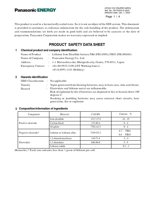
This product is used in a hermetically sealed state. So, it is not an object of the SDS system. This document is provided to customers as reference information for the safe handling of the product. The information and recommendations set forth are made in good faith and are believed to be accurate at the date of preparation. Panasonic Corporation makes no warranty expressed or implied.PRODUCT SAFETY DATA SHEET1 Chemical product and company identificationName of Product : Lithium Iron Disulfide battery FR6 (FR14505), FR03 (FR10G445)Name of Company : Panasonic Energy Co., Ltd.Address : 1-1Matsushita-cho, Moriguchi-city, Osaka, 570-8511, JapanEmergency Contact : +81-80-9932-3190 (JST Working hours)+81-6-6991-1141 (Holiday)2Hazards identificationGHS Classification : No applicableToxicity : Vapor generated from burning batteries, may irritate eyes, skin and throat.Hazard : Electrolyte and lithium metal are inflammable.Risk of explosion by fire if batteries are disposed in fire or heated above 100degrees C.Stacking or jumbling batteries may cause external short circuits, heatgeneration, fire or explosion.3Composition/information of ingredientsComponent Material CAS RN Content •i%•jPositive electrode Iron disulfide 1317-37-9 24 - 35 Carbon black 133-86-4 0 - 4 Graphite 7782-42-5 0 - 4Negative electrode* Lithium or Lithium alloy 7439-93-2 6.7 •iFR6) 6.6 •iFR03•jElectrolyte 1,2-dimethoxyethane 110-71-4 2 - 4 1,3-dioxolane 646-06-0 5 - 9 Lithium iodide - 0.3 - 3(Remarks) * Each size contains less than 1 gram of lithium per cell.4First aid measures (in case of electrolyte leakage from the battery)Eye contact : Flush the eyes with plenty of clean water for at least 15 minutesimmediately, without rubbing. Get immediate medical treatment.If appropriate procedures are not taken, this may cause eye injury.Skin contact : Wash the affected area under tepid running water using a mildsoap. If appropriates procedures are not taken, this may cause soreson the skin. Get medical attention if irritation develops or persists.Inhalation: Remove to fresh air immediately. Get medical treatmentimmediately.5 Firefighting measuresFire extinguishing agent : Alcohol-resistant foam and dry sand are effective.Extinguishing method : Be sure on the windward to extinguish the fire, since vapor maymake eyes, nose and throat irritate, Wear the respiratory protectionequipment in some cases.6Accidental release measures (in case of electrolyte leakage from the battery)Take up with absorbent cloth, treat cloth as inflammable.Move the battery away from the fire.7 Handling and storageHandling : žWhen packing the batteries, do not allow battery terminals tocontact each other, or contact with other metals. Be sure to packbatteries by providing partitions in the packaging box, or in aseparate plastic bag so that the single batteries are not mixedtogether.žUse strong material for packaging boxes so that they will not bedamaged by vibration, impact, dropping and stacking duringtheir transportation.žDo not short-circuit, recharge, deform, throw into fire ordisassemble.žDo not mix different type of batteries.žDo not solder directly onto batteries.žInsert the battery correctly in electrical equipment.Storage : •E Do not let water penetrate into packaging boxes during theirstorage and transportation.•E Do not store the battery in places of the high temperature orunder direct sunlight.žPlease also avoid the places of high humidity. Be sure not toexpose the battery to condensation, rain or frozen condition8.Exposure controls and personal protectionAcceptable concentration : Not specified about Lithium Battery.Facilities : Nothing in particularProtective Equipment (in case of electrolyte leakage from the battery)Respiratory Protection : For most condition no respiratory protection.Hand Protection : Safety gloves.Eye Protection : Safety goggle9.Physical and chemical propertiesAppearance : Cylindrical shapeNominal Voltage : 1.5 V10. Stability and reactivitySince batteries utilize a chemical reaction they are actually considered a chemical product.As such, battery performance will deteriorate over time even if stored for a long period of time without being used. In addition, the various usage conditions such as discharge, ambient temperature, etc. are not maintained within the specified ranges the life expectancy of the battery may be shortened or the device in which the battery is used may be damaged by electrolyte leakage.11.Toxicological informationSwallowing can lead to chemical bums, perforation of soft tissue, and death. Severe bums can occur within 2 hours of ingestion. Seek medical attention immediately.12.Ecological informationIn case of the worn out battery was disposed in land, the battery case may be corroded, and leak electrolyte. However, there is no environmental impact information.Mercury (Hg), Cadmium (Cd) and Lead (Pb) are not used in cell.13.Disposal considerationsWhen the battery is worn out, dispose of it under the ordinance of each local government.14.Transport informationHandlingDuring the transportation of a large amount of batteries by ship, trailer or railway, do not leave them in the places of high temperatures and do not allow them to be exposed to condensation.During the transportation do not allow packages to be dropped or damaged.Proper shipping name : Lithium metal batteriesUN Number, UN Class : UN3090, Class9 (for the Air transport by PI968 Section IA or IB): Exemption (for the Marine transport SP188 and the Air transportby Section II of PI 969 or 970)Even though the cells are classified as lithium metal batteries(UN3090 or UN3091), they are not subject to some requirements ofDangerous Goods Regulations because they meet the following:1. for cells, the lithium content is not more than 1 g ;2. each cell is of the type proven to meet the requirements of each test inthe UN Manual of T ests and Criteria, PartúL, sub-section 38.3.3. each cell is manufactured in ISO9001 certified factory.4. the test summary is available from;https:///ww/downloads/battery-test-summary Please refer to the following reference information about concrete ways of transportation. Actual content of packaging label and shipping documents varies by shipping companies. Make sure to confirm in advance with your shipping company.Information of referenceReference Packing Instruction(PI)/Special provision(SP)NoteAir transport IATA DGR PI 968 SectionúJ A Cells, Cargo Aircraft only; Net quantity perpackage Max. 35kgPI 968 SectionúJ B Cells, Cargo Aircraft only; net quantity perpackage Max. 2.5kgPI 969 SectionúK Cells packed with equipmentPI 970 SectionúK Cells contained in equipment Marine transport IMDG Code SP 18815.Regulatory information•E IATA Dangerous Goods Regulations Edition 64 (IATA DGR)•E IMO International Maritime Dangerous Goods Code 2020 and 2022 Edition (IMDG Code)•E UN Recommendations on the Transportation of Dangerous Goods, Model Regulations•E UN Recommendations on the Transportation of Dangerous Goods, Manual of Tests and Criteria •E EU Battery Directive•i2006/66/EC, 2013/56/EU)•E Regulation (EC) No. 1907/2006 on the Registration, Evaluation, Authorization and Restriction of Chemicals (REACH)•E State of California Regulations - Best management practices for Perchlorate Materials•E Act on Preventing Environmental Pollution of Mercury (Japan)16.Other informationThis PSDS is provided to customers as reference information in order to handle batteries safely.It is necessary for the customer to take appropriate measures depending on the actual situation such as the individual handling, based on this information.Prepared by: Engineering DepartmentEnergy Device Business DivisionPanasonic Energy Co., Ltd.。
雷欧力 千兆网络电源组合电涌保护器技术说明书

欧雷克千兆网络电源组合电涌保护器(又称:电源网络二合一防雷器,电源网络二合一避雷器,电源网络二合一电涌保护器)是依据IEC和GB标准设计,主要用于各类弱电设备、安防监控设备、电信设备、网络设备的电源和1000M网络信号线路的雷击电磁脉冲(LEMP)保护,是一体化多功能电涌保护器。
千兆网络电源组合电涌保护器技术说明书防雷器安装⽅法1、防雷器串联安装在被保护设备端口前(“INPUT”标识端接入线路,“OUTPUT”标识端与被保护摄像机相连接),PE端子接防雷地网。
2、线路端子接法(电源部分):交流电源:两端分别对应接“L1-L1”“L2-L2”,不分零火线; 直流电源:两端分别对应接“L1-L1”“L2-L2”,直流分正负极,正极接L1,负极接L2,且勿接错。
3、RJ45网络信号线路接法:串联安装,RJ45水晶头直接插接即可。
2 4、接地线截面应≥4mm ,且尽可能短。
安装本防雷产品要求接地电阻小于4欧姆,在接地线及接地电阻合格下防雷性能最优。
5、本防雷器免维护,雷雨后应及时检查和记录避雷器的工作状况。
防雷器安装注意事项1、防雷器输出端所有端口均连接被保护设备。
2、正负线路请勿接反或接错,切记不可带电作业。
3、防雷器安装在被保护设备前端越近效果越好。
4、设备需要定期检查,产品劣化后必须立即更换。
5、接地一定要良好且接地电阻不大于4欧姆。
防雷器技术参数防雷器尺寸及接线图功能特点产品介绍1、通流容量大:10KA(8/20μS),电源线路采用两级复合平衡线路,交流不分零/火线,零/火线随便接(直流需分正负极),差模、共模全保护。
2、电源、1000M网络防雷二合一设计理念,不占空间;3、能有效防止电源、网络等线路间电位差瞬时增大而造成的设备损坏;4、内部采用两级串联式复合型保护,残压低,使用寿命长;5、电源电涌保护端口带LED失效指示(绿色:正常;熄灭:失效);6、采用集成化结构、体积小、接线简易、安装方便。
Zr
,
,
W ANG T a i Yil la1 W ANG g- Fu. i hu ,
,
QI NG in | U e-ig ,WAN D - e,DON C u n I A Ja - l ,X W i n ' g p G eh G h a g
( . tt K ylb rt yfr t il Mo ict n b ae ,Ina dEet n B a ,D l n U i r t o 1 Sa e a oao e as df ai yL sr o n lc o ems ai nv s y f e r o Ma r i o r a e i
Ac d my o ce c s h n a g 1 0 6,C ia a e fS in e ,S e y 01 n 1 hn )
Absr c Th l to h mia o r so e a i ro i - 一 — ul t lc ga s d t rsa o tr t a t: e ee r c e c c ro i n b h v o fsx ZrA1NiCu b k me a i l s e a wo c t c un e — c l l s n y l pa t r t d e y e e to h mia t o n 0. l Na S ou in.P e ZrWa s n e tg td f rc mp r— rs we e su id b l r c e c me d i 1mo/L 2 04s l to c l h ur s a o i v ia e o o a i l s s n.Re u t h we a e c ro i n b h vo s e e d d o he c mp sto o s ls s o d t tt o r so h h e a i rWa d p n e n t o o iin.Alo 6 Al 5 mCu1 5 h d t e ly Zr5 7 Ni 7 a h
海康威视总线制报警主机操作手册

3.1 总线式网络报警主机启动 ...................................................................................................... 20 3.2 报警键盘启动 .......................................................................................................................... 20 3.3 键盘编址 .................................................................................................................................. 20 3.4 出厂设置 .................................................................................................................................. 21
工作状态指示灯 网络状态指示灯 电源指示灯
GPRS模块
SIM卡槽
D+ D- +12V G
COM1
COM2
COM3
COM4
奥瑞那集团产品说明书
OX620火栓按钮使用说明书V1.01.0 概述1.1 OX620消火栓按钮(以下简称按钮),是人工发送报警信号、启动水泵及显示水泵运行指示的部件。
1.2 该按钮具有控制器自动编址和电子编码器编址两种编址方式。
与我公司生产的OZH4800型火灾报警控制器配合使用。
自动编址方式参见控制器使用说明书,电子编码器编址方式参见电子编码器使用说明书。
2.0 结构特征及工作原理2.1壳体材料和颜色采用ABS 复合塑胶设计成型,外观红色、安装方便。
2.2工作原理、工作特性该按钮采用MCU 单片机微处器。
当按钮安装位置附近发生火情时,觉察人员按下消火栓按钮的中心面板后,按钮报警红灯亮,同时向火灾报警控制器发出火警信号,控制器显示按钮对应的预先编好的具体位置并发出火警声。
2.3 主要部件该消火栓按钮是由按钮开关、线路板,外壳主要部件组成。
3.0 技术特征3.1 工作电压:DC20V ~ 30V3.2 监视电流: ≤250uA报警电流:≤2mA3.3 线制:二总线,无极性3.4 地址设定范围:1~192号3.5 触点容量:DC24V/1A3.6 环境条件:温 度 -10℃~+50℃。
相对湿度 ≤95%(40±2℃)3.7尺寸长:85mm 宽:85mm 高度:38.5mm4.0 安装4.1 安装基础、条件及要求4.1.2 安装前消火栓按钮应保存在防尘、防潮、防霉的地方。
4.2 消火栓按钮的布线4.2.1 要求用截面积1mm 2以上的铜质双绞线,每米绞合节数为20~30,导线总电阻低于60Ω,总分布电容低于0.2uF 。
在总线负载较重的情况下,宜根据实际最大负载电流计算导线压降,以保证现场单元得到20V 以上的总线电压。
4.2.2 屋顶的穿线管在装入底座后应使用密封膏或密封胶封堵,防止积水进入消火栓按钮。
4.2.3 接线时导线应使用冷压接线端子或做镀锡处理,不可随意缠绕。
避免线头接触不良。
4.3 接线:各端子见图右图。
(完整版)机械密封
机械密封每一种机械密封,只有用于规定的范围内才能有效地发挥作用.选型不当,则会使密封性能显著降低,寿命缩短,甚至失效。
选型的主要参数如下一、密封腔介质压力P :介质润滑性好,粘度较高时,P≤0。
8MPa选用非平衡型。
介质润滑性差,粘度低时,P≥0。
5Mpa二、线速度V:V≤25m/s选用旋转型。
V≥25m/s时选用静止型。
三、PV值:PV值涉及到密封面之间流体膜的稳定性(汽化)和磨擦副的耐磨性。
PV极限值举例:四、密封介质温度T在没有外冷条件下,机械密封的最高温度一般取决于辅助密封材料的安全使用温度。
见下表:五、介质的特殊性。
1、粘度:低粘度介质易干磨擦宜选用平衡型。
高粘度介质,宜采用强制传动结构。
2、腐蚀和化学溶剂: a、强腐蚀宜用外装式的四氟波纹管密封。
b、辅助密封在不同化学介质中的适用表如下:3、含悬浮固体颗粒:动静环材料宜采用碳化钨/碳化钨,或碳化硅/碳化硅,当颗粒易于阻塞密封腔时,须采用辅助装置经过过滤或分离后的冲冼液,冲洗端面。
4、剧毒或气体介质 :宜采用双端面机械密封。
订货须知机械密封为主机服务,必须根据主机的具体工况条件来选择密封的结构型式和材料组对,以确保机械密封安全、可靠、持续有效地发挥作用。
为使用户正确面经济地选用我厂产品,订货时请按《选型参数表》认真填写后寄给我们.谢谢合作!密封选型参数表:机械密封安装使用要求机械密封是精密部件,制造及安装精度都要求很严格,如果装配不当会影响密封性能,因此必须注意以下要求: 1、安装机械密封部位的轴(或轴套)的技术要求应按下表规定:类别轴径(mm)径向跳动(mm)表面粗糙度(Ra)外径尺寸公差转轴轴向跳动(mm)泵用10-50≤0。
04≤1.6h6≤0。
1〉50-120≤0。
06釜用20-80≤0。
4≤1。
6h6≤0.5 >80-130≤0.62、安装旋转环辅助密封圈的轴(或轴套)的端部应按下图倒角:3、安装静止环辅助密封圈的端盖(或壳体)孔的端部及表面粗糙度应按下表及图的规定:类别轴径(mm)C(mm)α泵用10—161。
Evolis Primacy 智能卡打印机产品说明书

STANDARD PRINTER FEATURES SOFTWARE PRINTER SPECIFICATIONS Printer design:Delivered with driver for Windows ® XP SP3 32/64,Physical dimensions (H x W x D):• Central mechanical locking system Vista 32/64, W7 32/64, W8 32/64, W10• Without hoppers: • Interchangeable 500-card input & output hoppers• User interface languages available: English, French,215 x 300 x 850 mm (8.46" x 11.81" x 33.46")• Available in aluminium body, black plastic coversSpanish, German • With hoppers: Print technology:Delivered with cardPresso XXS for designing and 567 x 300 x 850 mm (22.32" x 11.81" x 33.46")• Direct-to-cardediting badges:Weight:• Dye-sublimation/resin thermal transfer• Internal database (unlimited records)• 21,7 kg (47.8 lbs)Print capability:• Signature acquisition (compatible with Evolis Sig100Electronic requirements:• One-or two-sided printing, edge-to-edgeand Sig200 signature pads)• Power supply: 100-240 Volts AC, 50-60 Hz, 2 A Print resolution:• Compatible with Windows ® XP SP3 32/64, Vista 32/64, • Printer: 24 Volts DC, 6.25 A • 16 million colorsW7 32/64, W8 32/64 and Mac OS X (Intel® processor)• 300x300 dpi (dots per inch)Delivered with a driver for Mac OS X (from 10.5 onwards)OPERATING ENVIRONMENT Printing performance:Linux OS, upon request • Min / Max operating temperature: 15° / 30° C (59° / 86° F)• Color YMCKO: up to 150 cards/hour 1 single-sidedSDK for remote supervision of the printer, while • Humidity: 20% to 65% non-condensing • Color YMCKO-K: up to 115 cards/hour 1 dual-sidedfacilitating and speeding up integration into IT systems • Min / Max storage temparature: -5° / +70° C (23° / 158° F)• Monochrome: up to 1000 cards/hour 1 single-sided• Storage humidity: 20% to 70% non-condensing • Monochrome: up to 320 cards/hour 1 dual-sidedPRINTER RIBBON SPECIFICATIONS • Operating ventilation: free air Printer memory:The Primacy is designed to work only with Evolis • 16 MB (RAM) allowing two card storagesHigh Trust ® ribbons SOUND (evaluated according to the ISO 7779 Interfaces:To maximize the quality and durability of printed Sound pressure in assistant positions LpAm (color mode • USB (1.0, 1.1, 2.0, 3.0)cards, the lifespan of the print head and the overall YMCKO):• Ethernet TCP-IP, 10BaseT, 100BAseT (Traffic Led)printer reliability, use Evolis High Trust ® ribbons • When operating: 50 dB (A)Safety:• Ribbon saver for monochrome printing • In sleep mode: background noise level • Centralized locking system• Recycled packaging Display:Ribbon capacity:CERTIFICATIONS / COMPLIANCES • 2-line LCD display• YMCKO: 500 prints/roll • CE, FCC, VCCI • Status LED for printer and encoding unit monitoring• YMCKO-K: 500 prints/roll (dual-sided)• RoHS • User interface languages available: English,• 1/2 YMCKO: 400 prints/roll French, Spanish, German, Italian, Portuguese• KO: 500 prints/roll INCLUDED WITH THE PRINTER Warranty:• Black monochrome ribbon: 3000 prints/roll • CD with drivers and user's manuals • 1-year warranty on printer (limited to 500,000insertions 4• BlackFLEXmonochrome ribbon: 1000 prints/roll • DVD with cardPresso XXS card designer software insertions)4• Blue P300C monochrome ribbon: 1000 prints/roll • Quick Start Guide • 1-year warranty on original print head (limited to• Red P186C monochrome ribbon: 1000 prints/roll • Warranty booklet 500,000 insertions)4• Green P356C monochrome ribbon: 1000 prints/roll • Starter cleaning kit • White monochrome ribbon: 1000 prints/roll • USB cable (1.80m)OPTIONAL PRINTER FEATURES• Metallic silver monochrome ribbon: 1000 prints/roll • Power supply • Locking system to prevent acces to the printer• Metallic gold monochrome ribbon: 1000 prints/roll • Power cord (region specific)and consumables (cards and ribbons)• Signature panel monochrome ribbon: 1000 prints/roll • Quantum Production Pack: 1 detachable card hopper• Scratch-off monochrome ribbon: 1000 prints/roll with short door, 2 cleaning rollers, 1 cleaning kit• Hologram varnish ribbon: 350 prints/roll • Quantum Backup Pack: 1 print head, 1 reversibleencoding module, 1 detachable card hopper withY=Yellow, M=Magenta, C=Cyan, K=Black Resin short doorO=Overlay, S=Silver • Detachable hopper (long or short doors) with acapacity of 500 card (0,76mm - 30mil)CARD SPECIFICATIONS • Warranty extension program• Detachable and interchangeable card input feeder and output stacker with 500 cards capacity (0,76mm -ENCODING OPTIONS30mil)• Reversible upper and lower encoding unit for• Reject hopper for defective cards with a capacity magnetic stripes and contact smart cards (patented)of 20 cards (0,76mm - 30mil)• Magnetic stripe encoder ISO 7811, track 1, 2 and 3• Card thickness: 0,76 to 1mm (30 to 40mil)high and low coercivity, stripe down (0,76mm - 30mil• Gauge adjustment cards only)Card types accepted:• Magnetic stripe encoder JIS Type II• ISO 7810 format, Type ID 1, CR-80 size • Smart card contact station ISO 7816-2 for 3rd party• 85,6 x 53,98 mm (3.370" x 2.125")external encoder• PVC, Composite PVC, PET • Connecting panel and mounting area for users• ABS 1, special varnished cards 1own integration of encoding units• Contact smart encoder - PC/SC, EMV 2000-1• Contactless ISO 14443A, B, ISO 15693, MIFARE,DESfire, HID iCLASS• Other specific encoders upon request• Options can be combined• Factory-installed or installed on-site CARD PRINTER SPECIFICATIONS ©2015 Evolis. All rights reserved. All information, specifications or graphics are subject to change without prior notice. All trademarks mentioned herein belongto their respective owners. 08/2015. KB-QTM2-127-ENG-A4 Rev A0 Under specific conditions / Depends on the Windows® version / Requires 4.0 client profile version Warranty subject to observance of specific conditions and use of Evolis High Trust® ribbons。
第1-24课总复习测试卷(4) 新版标准日本语初级上册

一、选择题io 高槁:</代、天氛xM*;h 。
山田TTfeo _________________ 、高今晚07^—行芝宝寸力、。
A r.6^?B <k r 6^ c iz^b D11日本仲法律20赢力、§右酒在 __________________________ o A V B 欺Ay/^± 5 力竣、L 、。
可C 欺/17。
七1/、1/、。
寸D ^A/fcfr V ^'t12 私m 每朝。
一匕一在 ______________A 2枚B 2杯C 2足D2通13 外力、以猫(7)声_行K 暮亲L Jz 9oAB 力土CD14 学校©食堂_ ______ 1^61^6^ 料理在食-<drAB 顽土C ED15春【以土赤</、花— _______ 白(/、花、V^5V^6^花力土联老京可。
A 力二BC H D16 璟境保膏蔓片— _______ 在持 n 人 ^^x.XV^^oA 趣味B 心配C 氛分D 所、17 亦 力、以手纸仔返事9匕思、v^ToA 考;tB 考灯C 考;D : #X_d18 r 所八来/co (i —_____ ^CToA 初«B 初珈乙C 始o/cD 初於19 2^—yU/Ky迷惑让,一 3 _____________ 七入 oXV^ L/z oA 10 通B 10 $fC 10 本D 10 册 20 _______ 书速 T^/Z O'T?、怖 A X t°— K B 人力一卜C X^-—D 又 _.J21 王:E 。
,料理在食忒京世A >力、。
李:^Xt 辛1/、。
可力、以。
A.寝 A前记、X* 7-^浴#京可。
B.寝I (7)赤L 、帽子 _________B 力二L oB 力二本屋力、§辞害A I :母旅行社v y 卜A T' A (5^< XB 彼女l 乙会十EsW 基A O'X?B私怵携带力* _________ A y 。
霍格桑斯C完整型电路保护器说明书
Eaton FDC3070VEaton Series C complete molded case circuit breaker, F-frame, FDC, Complete breaker, Fixed thermal, fixed magnetic trip type, Three-pole, 70A, 600 Vac, 250 Vdc, 200 kAIC at 240 Vac, 100 kAIC at 480 Vac, Load side, 50°C, 50/60 HzGeneral specificationsEaton Series C complete molded case circuit breakerFDC3070V 7866793976023.38 in 6 in4.13 in 4.5 lbUL ListedProduct NameCatalog Number UPCProduct Length/Depth Product Height Product Width Product Weight CertificationsSeries C100 kAIC at 480 Vac200 kAIC at 240 VacFFDC50/60 HzComplete breakerLoad side50°C600 Vac, 250 Vdc70AFixed thermal, fixed magnetic Three-pole UL listed 100%-rated molded case circuit breakersApplication of Tap Rules to Molded Case Breaker Terminals Application of Multi-Wire Terminals for Molded Case Circuit BreakersCircuit breaker motor operators product aidMOEM MCCB Product Selection GuidePlug-in adapters for molded case circuit breakers product aidPower metering and monitoring with Modbus RTU product aid StrandAble terminals product aidCurrent limiting Series C molded case circuit breakers product aidMulti-wire lugs product aidMotor protection circuit breakers product aidCounterfeit and Gray Market Awareness GuideBreaker service centersMolded case circuit breakers catalogEaton's Volume 4—Circuit ProtectionFDC3 3D InventorTime Current Curves for Series C® F-Frame Circuit BreakersFDC3 3D Model XchangeFDC3 AutoCAD 2D Footprint (mm)Installation Instructions for EHD, EDB, EDS, ED, EDH, EDC, FDB, FD, HFD, FDC, HFDDC Circuit Breakers and Molded Case SwitchesCircuit Breakers ExplainedCircuit breakers explainedSeries C F-Frame molded case circuit breakersSeries C G-Frame molded case circuit breakers time current curves MOEM MCCB product selection guideSeries C J-Frame molded case circuit breakers time current curvesEaton Specification Sheet - FDC3070VSeriesInterrupt ratingFrameCircuit breaker type Frequency ratingCircuit breaker frame type TerminalsCalibrationVoltage rating Amperage RatingTrip TypeNumber of poles Application notesBrochuresCatalogsDrawingsInstallation instructions MultimediaSpecifications and datasheetsEaton Corporation plc Eaton House30 Pembroke Road Dublin 4, Ireland © 2023 Eaton. All Rights Reserved. Eaton is a registered trademark.All other trademarks areproperty of their respectiveowners./socialmedia。
达塔数据盘型PS6600WC商品说明书

Structure
IP66F, IP67F, UL 50/50E,Type 1, Type 4X (indoor use only),Type 12,Type 13 NOTE:On the front panel when properly installed in an enclosure.
Weight
Voltage Drop
5 ms or less
20 ms or less
5 ms or less
20 ms or less
Power Consumption*4
Panel Unit Only: 73 W When power is not supplied to external devices (Max 138 W) Box Unit Only: 56 W When power is not supplied to external devices (Max 121 W)
Projected capacitive (multi-touch)
261.12 x 163.2 mm (10.28 x 6.43 in)
White LED (not user replaceable. Please contact customer support.)
50,000 hours or more (continuous operation at 25 °C [77 °F] before backlight brightness decreases to 25%)
260-pin SODIMM socket x 2, DDR4-2133 (Up to 16 GB/socket, up to 32 GB for 2 sockets)
Intel® UHD Graphics 620 (built in CPU)
佳能复印机-维修手册(双面单元-A1)中文版

荣 将会以维修信息公告的方式进行交流。
所有维修人员均应对本维修手册以及所有相关的维修信息公告板的内容进行深入的理
共享光 解和掌握,并且具有对设备故障进行识别、分析的能力。
共享光荣
目录
目录
第 1 章规格 1.1 产品规格 ................................................................. 1-1
4.1.2 消耗品 ............................................................... 4-1 4.1.2.1 消耗品 ........................................................... 4-1
介绍
所使用的符号
本文件使用下列符号表示专用信息。
符号 说明
表示非特定性质的项目,可能被列为 “注意” . “小心” . “警告”
表示需要小心以防止电击项目
表示需要小心以防止燃烧 (火灾)项目 表示禁止分解以防止电击或者电路问题的项目 表示需要从电源出口切断电源插座的项目
荣 表示旨在提供注意事项协助理解讨论中主题的项目
5.2.1 卡纸代码清单 ......................................................... 5-1
欧姆龙RFID
⑤本产品目录中述及的应用事例仅作为参考之用,实际使用时,应事前确认设备·装置的功能以及安全性等 之后,再进行使用。
Con la presente Omron dichiara che la RFID Sistema, V680-HS52Serie, V680-HS63 Serie, V680-HS65 Serie, V680-HA63B Serie sono conforme ai requisiti essenziali ed alle altre disposizioni pertinenti stabilite dalla direttiva 1999/5/CE.
6.价格
本手册中记载的标准价格仅供参考。此价格中不包含消费税。
7.适合范围
上述内容仅限日本国内地区的交易。 其他地区和海外的交易及使用注意事项请与当地销售网点的人员咨询。
RFID 系统
操作手册 3
前言
前言
安全注意事项
●安全使用警告标志 本说明书中的以下标志用于指出在确保安全使用 V680-HS63/-HS52/-HS65/-HA63B 和 V680-D2KF67/-D2KF67M/D2KF52M/-D8KF68/-D32KF68系统时,必须警惕的地方。这些注意事项中包含重要的安全信息,请务必阅读。
前言
放大器 V680-HA63B
天线
V680-HS52 V680-HS63 V680-HS65
英语 芬兰语 荷兰语 法语 瑞典语 丹麦语 德语 希腊语 意大利语 西班牙语 葡萄牙语 罗马尼亚语
pro-face sp5000系列 硬件手册说明书

目录
SP5000-MM01-CS-PDF_O
安全信息 ....................................................................................................7 关于本书 ....................................................................................................8 概述......................................................................................................... 11
对于将本指南或其内容用作商业用途的行为,施耐德电气未授予任何权利或许可,但 以“原样”为基础进行咨询的非独占个人许可除外。
施耐德电气的产品和设备应由合格人员进行安装、操作、保养和维护。
由于标准、规格和设计会不时更改,因此本指南中包含的信息可能会随时更改,恕不 另行通知。
在适用法律允许的范围内,对于本资料信息内容中的任何错误或遗漏,或因使用此处 包含的信息而导致或产生的后果,施耐德电气及其附属公司不会承担任何责任或义 务。
标准主机模块 ................................................................................28 增强型主机模块............................................................................. 30 开放型主机模块............................................................................. 32 LED 指示 ......................................................................................34 显示模块 ............................................................................................35 精良显示模块 ................................................................................35 高级显示模块 ................................................................................39 LED 指示 ......................................................................................42 规格......................................................................................................... 44 一般规格 ............................................................................................44 电气规格....................................................................................... 44 环境规格....................................................................................... 46 结构规格....................................................................................... 47 功能规格 ............................................................................................49 显示规格....................................................................................... 49 存储器 ..........................................................................................51 时钟 .............................................................................................51 触摸屏 ..........................................................................................51 接口规格 ............................................................................................52 接口规格....................................................................................... 52 接口连接....................................................................................... 54 用于 COM1/COM2 的串行接口 (RS-232C 和 RS-422/RS485) .............................................................................................57 辅助输出/扬声器输出接口 (AUX) ....................................................59 DVI-D 输出接口.............................................................................60 尺寸......................................................................................................... 62 标准主机模块...................................................................................... 62 SP-5B00 ......................................................................................62 增强型主机模块 ..................................................................................63 SP-5B10 ......................................................................................63 开放型主机模块 ..................................................................................63
华为CloudEngine系列交换机FCoE和DCB技术白皮书

CloudEngine 8800&7800&6800 系列交换机FCoE 和DCB 技术白皮书目录1FC SAN 简介 (1)2FCoE 简介 (2)3FC 原理描述 (5)3.1FC 的基本概念 (6)3.2FC 的工作原理 (8)3.3FCF (8)3.4NPV (9)3.5Zone (10)4FCoE 原理描述 (12)4.1FCoE 的基本概念 (13)4.2FCoE 的封装 (15)4.3FIP 协议 (16)4.4FSB (19)5应用场景 (22)5.1FCF 场景 (23)5.2FCF+NPV 组网 (24)5.3FCF+FSB 组网 (26)6配置任务概览 (28)7配置注意事项 (29)8兼容性列表 (33)9缺省配置 (53)10配置FCF. (54)10.1配置FC/FCoE 接口 (57)10.2(可选)配置FC 接口参数 (58)10.3配置FCF 实例 (59)10.4配置Zone (59)10.5(可选)配置FCF 参数 (61)10.6(可选)指定FCoE 流量端口 (61)10.7(可选)配置FIP Keepalive 报文的发送间隔 (63)10.8检查配置结果 (63)11配置NPV. (64)11.1配置FC/FCoE 接口 (67)11.2(可选)配置FC 接口参数 (68)11.3配置NPV 实例 (69)11.4(可选)配置接口映射关系 (70)11.5(可选)配置FIP Keepalive 报文的发送间隔 (70)11.6检查配置结果 (71)12配置FSB (72)12.1配置FSB 实例 (74)12.2配置接口角色 (74)12.3(可选)配置FIP 协议报文的交互超时时间 (75)12.4(可选)配置FCoE 链路同步功能 (76)12.5(可选)使能协议报文隔离功能 (76)12.6检查配置结果 (77)13维护FCoE (78)13.1查看FIP 报文的统计信息 (79)13.2清除FIP 报文的统计信息 (79)13.3查看FC 和FIP 报文的统计信息 (79)13.4清除FC 和FIP 报文的统计信息 (80)13.5监控FCoE 的运行状态 (80)14配置举例 (81)14.1配置FCF 示例(FC 接口) (82)14.2配置FCF 示例(FCoE 接口) (85)14.3配置FCF 示例(FC 和FCoE 接口) (89)14.4配置FCF+NPV 示例(FCoE 接口) (93)14.5配置FCF+NPV 示例(FC 和FCoE 接口) (100)14.6配置FCF+FSB 示例(FCoE 接口) (105)15DCB 简介 (112)16DCB 原理描述 (113)16.1 PFC. (114)16.2 ETS (116)16.3 DCBX (118)17 应用 (122)18配置任务概览 (123)19配置注意事项 (124)20缺省配置 (126)21配置PFC 功能 (127)22配置ETS 功能 (129)22.1配置ETS 模板 (130)22.2应用ETS 模板 (131)22.3检查配置结果 (131)23配置DCBX 功能 (132)24维护DCB (134)24.1监控DCB 的运行状态 (135)24.2清除DCB 的统计信息 (135)25配置举例 (136)25.1配置DCB 示例 (137)1FC SAN 简介介绍FC SAN 的定义和作用。
低温韧性好的尼龙66复合物

低温韧性好的尼龙66复合物
严淑芬
【期刊名称】《现代塑料加工应用》
【年(卷),期】2016(28)5
【摘要】据“www.ptonline.com”报道,罗德岛波塔基Teknor Apex公司全新升级的尼龙66复合物Chemlon109 HBK778,与通用的尼龙66相比,其在低温下冲击强度更好,且提高了寒冷天气下注射成型的性能,可应用于不同的紧固件,如燃料罐喷嘴、扎带、活铰链和体育器材。
【总页数】1页(P15-15)
【关键词】尼龙66;低温韧性;复合物;Apex公司;.com;冲击强度;注射成型;体育器材
【作者】严淑芬
【作者单位】中国石化扬子石油化工有限公司南京研究院
【正文语种】中文
【中图分类】TQ323.6
【相关文献】
1.有机化纳米SiO2填充尼龙66复合物的结构与性能 [J], 卢会敏;徐翔民;李小红;张治军
2.有机化蒙脱石填充尼龙66复合物的结晶与热力学行为研究 [J], 柯林萍;阳明书;吴长勇
3.碳纳米管/尼龙66复合物的纳米压痕和结晶性能研究 [J], 邱丽;杨永珍;徐丽华;刘旭光;许并社
4.超韧性增强尼龙66的研究 [J], 张炳生;沈遒
5.增韧尼龙66的制备及耐低温性能 [J], 马小丰;金旺;刘莉莉;李建华
因版权原因,仅展示原文概要,查看原文内容请购买。