残压测速说明书
东堡8筒压力检测试佛文件说明书

8PCCOMPRESSION TEST KITINSTRUCTIONSItem #31351}2 EastwoodTechnicalAssistance:800.544.5118>>********************The EASTWOOD 8 PIECE COMPRESSION TEST KIT includes all the components required to obtain accurate cylinder compression readings for diagnosing the internal condition of gasoline engines. Con-structed of high-quality brass and steel components, the four most popular spark plug thread sizes are represented in the set along with convenient bung-style adapters for universal use.AB CD CONTENTS(4) Spark Plug Thread Fittings (A), M10, M12, M14 & M18(1) 20” Hose (B)(2) Adapter Fittings with Rubber Bungs (C)(1) Compression Gauge (D)(1) Heavy-Duty, Blow Molded CaseCREAD INSTRUCTIONS• Thoroughly read and understand these product instructions before usingthe Compression Tester.• Keep these product instructions for future reference.IMPROPER MOTOR VEHICLE REPAIR WORKCAN RESULT IN INJURY OR DEATH!• Performing automotive repair work can cause injury, death and vehicleaccidents. DO NOT attempt to use this tool or begin motor vehicle enginework without proper training and a thorough understanding of motor vehiclemechanical systems.• Always consult an authorized manufacturer’s service manual or referencematerials on the particular vehicle for the proper procedures before usingthis tool.SUDDEN VEHICLE MOVEMENT CAN RESULTIN INJURY OR DEATH!• Block vehicle wheels before use. Set parking brake and put gear selectorin neutral for manual transmission or park for automatic transmission.• Immobilize a vehicle before working on it.HEALTH HAZARD!• Avoid carbon monoxide poisoning!• Never run a gasoline engine in an enclosed garage or other contained area. DANGER indicates a hazardous situation which, if not avoided, will result in death or serious injury. WARNING indicates a hazardous situation which, if not avoided, could result in death or serious injury. CAUTION used with the safety alert symbol, indicates a hazardous situation which, if not avoided, could result in minor or moderate injury.NOTICE is used to address practices not related to personal injury.The following explanations are displayed in this manual, on the labeling, and on all other information provided with this product:4 EastwoodTechnicalAssistance:800.544.5118>>******************** FIRE AND EXPLOSION HAZARD!• Gasoline fumes can be released while cranking engine. Do Not Smoke!No Open Flames! Eliminate possibility of ignition sparks.BURN HAZARD!• Avoid contact with hot engine components! SHOCK HAZARD!• Contact with high-voltage ignition current can cause serious injury or death. • Disable ignition while using the Compression Tester to avoid exposure tohigh voltage ignition shocks.INJURY HAZARD!• Contact with moving or rotating engine components can causeserious injury!• Keep hands and fingers away from fans, belts and other movingengine components while using the Compression Tester.• Using the Compression Tester requires the help of an assistant; a personto operate the starter and another to use the Compression Tester.To order parts and supplies: 800.345.1178 >> 5OPERATION• To achieve accurate compression readings, an engine must first be at full operating temperature before taking readings.• After warming up engine, disable ignition by removing the coil to distributor cable on engines so equipped. Consult an authorized service manual or materials on later model engines.• Remove the spark plugs from all cylinders. Be sure to note the location of ignition cables to respective cylinders.• Select the appropriate sized Spark Plug Thread Fitting (A) that matches the spark plug threads of the engine and thread the end of the Hose (B) into it.• Thread the Spark Plug Thread Fitting and Hose assembly (A & B) into the first spark plug hole and attach the Gauge (D) to the quick-disconnect end of the Hose.NOTE: As an alternative, the Straight or Angled Adapters (C) may also be attached to the Gauge (D) and used directly by pressing the Rubber Bung against the spark plug hole however best results are achieved with low compression engine use only.• With the Compression Tester connected to the first cylinder of the engine, crank the engine for 30 seconds.NOTE: On carbureted engines, the choke and throttle must be held open while cranking to achieve an accurate reading. Consult an authorized service manual or materials on later model and fuel injected engines.• While the engine is cranking, the Gauge will automatically record the highest compression reading as displayed on the Gauge. Consult an authorized vehicle manufacturer service manual or materials for specified engine compression values.NOTE: In addition to recording cylinder compression values, further indications about cylinder condition can be obtained by observing the Gauge action while cranking. Normal engine cylinder compression will be indicated with a high initial reading, and a progressive build-up to the final maximum reading. Poor engine cylinder compression will be indicated with a low initial reading, and a much slower build-up to the final maximum reading. The compression readings for all of the engine cylinders should not vary by more than 10%.• After recording the maximum reading, the pressure may be released and Gauge reset by pressing the Compression Release button on the Gauge (D).• Disconnect the Compression Tester from the first cylinder and move on to the next cylinderrepeating the above steps for all remaining cylinders.ADDITIONAL ITEMS#14534Eastwood Valve Spring Compressor#1453310pc Bearing & Seal Driver Set#46281Dial Type Cylinder Bore Gauge Kit, 2-6" Range#45056Engine Porting KitTo order parts and supplies: 800.345.1178 >> 7If you have any questions about the use of this product, please contact TheEastwoodTechnicalAssistanceServiceDepartment:800.544.5118>>email:******************** PDF version of this manual is available online >> /31351manualThe Eastwood Company 263 Shoemaker Road, Pottstown, PA 19464, USAUS and Canada: 800.345.1178 Outside US: 610.718.8335Fax: 610.323.6268 © Copyright 2016 Easthill Group, Inc. 9/16 Instruction item #31351Q Rev 1。
残压测速说明书

ZDZK-III(C)-1电脑转速测控仪使用说明书四川中鼎自动控制有限公司地址:成都市武兴四路11-13号电话:(028)85080508传真:(028)85090402邮编:610041主要技术性能测量信号路数:两路,①齿盘传感器(DZK-C-1)或永磁机频率Ma(DZK-III-1)②发电机频率Pt测频范围:1~100Hz齿盘输入中心频率可有25Hz、50Hz、100Hz三种选择。
输入电压:0.3~250VAC测量精度:0.1%±1字数显内容:机组频率,发电机频率,转速百分数,转速百分数最大值,各路输出整定值输出信号:8路,1-6点(J1-J6)输出常开触点,初值为中心转速的5%ne、15%ne、50%ne、80%ne,95%ne、140%ne。
第1、2点为小于等于设定值闭合,第3-6点为大于等于设定值闭合,有1Hz的回差值。
每点可由用户在所定范围内设定。
第6点为机组过速保护输出,有两对触点输出。
第7点(J N)为扩展控制输出,为一组转换接点,动作值可在全量程范围内设置,可选择设置是大于设定值动作或小于设定值动作。
第8点(J W)为报警输出常闭触点,机组正常工作时触点断开,在仪器失电;传感故障;机组惰转时,触点闭合,发出报警信号。
标准模拟量输出:对应于机组转速0%~200%,输出4~20mA电流输出接点容量:5A/250VAC,0.5A/220VDC最大值记忆:能记忆显示转速最大值n M%,可由用户清除。
工作环境:温度0~50℃,湿度<85%外形尺寸:盘装160×80×250mm工作方式:连续工作电源:交直流两用85V~260V功耗:8W一概述DZK系列电脑转速测控仪经历十年的应用与改进,已成功应用于全国数百个水力发电厂,获得用户一致好评。
DZK-C-1和DZK-III-1在原有DZK系列电脑转速测控仪功能上又作了重大改进,使功能更齐全、性能更可靠。
主要改进有:1、连接端子全用进口菲尼克斯端子。
转速仪表使用说明书
SAIL-ZKZ-III 电厂转速智能控制仪表使用说明书一、概述电厂转速监控装置可以同时输入两路信号测量,显示机组转速/频率、转速百分比/转速最大值等,还具有传感器的断线报警、故障(蠕动)报警以及对应机组转速8 个报警点输出等功能。
该测控仪充分利用单片机的特长,实现了精度高、功能强、高可靠、易操作等优点。
其最突出的优点在于只与测量信号的频率有关而与信号电压幅值无关,因而特别适合低残压信号的测量。
它集频率表、转速表、转速继电器、转速测试仪表于一体。
不用担心转速接点出口值因长期运行而变化,提高了可靠性,该测控仪还能保存记忆当前机组转速最大值,这给机组甩负荷实验,事故过速分析带来极大方便。
测控仪采用回差方式消除出口继电器抖动,对于机组刹车引起的波形畸变,则采用闭锁方式防止输出误动作,根据电厂运行需要,可以在现场方便地对8 个转速出口值进行一定范围的整定。
该仪表还具有标准电流输出、Modbus-RTU 模式RS485 通讯接口,可以方便的与计算机接口,可作为水电厂全厂计算机监控系统的组成部分。
二、技术性能测量输入信号:一路标准脉冲信号,测量转速;一路PT 信号,测量发电机输出频率测量频率范围:PT 为0.3~150Hz/0.2~250V ,标准脉冲信号0 ~ 8KHz 测量精度:0.1 %士1 字显示内容:机组转速/频率、转速百分比/ 转速最大值输出信号:八路报警继电器,每点可在0~200% 的范围内自由设定;一路发动机组蠕动故障报警;一路断线报警输出触点容量:A1~A8 为5A/250VAC、5A/30VDC ;故障和断线为3A/250VAC、3A/30VDC 模拟量输出: 4 ~ 20mA 、0 ~ 10mA 、0 ~ 20mA通讯输出:Modbus-RTU模式,RS485接口,波特率最大为19200 bit/s最大值记忆:能记忆显示转速大值,可由用户清除工作环境:温度0~50 C 湿度:< 85 %工作电源:开关电源100~260VAC/DC外形尺寸:160X80X125mm 开孔尺寸:152X76mm功耗:5W三、仪表操作说明1 6 Omni报警指示灯AL1~AL8、故障报警指示灯ERR与断线报警指示灯CVT,每个指示灯都有对应的输出继电器。
GYWB6齿盘测速及残压测速式转速继电器校验装置使用说明书

GYWB6型齿盘测速及残压测速式转速继电器校验装置使用说明书目录一、概述 (2)二、主要技术性能 (2)三、工作原理 (3)残压检测 (3)四、面板说明 (4)五、操作说明 (5)1、环抱式测速安装 (5)2、齿链式测速安装 (6)3、轴端式测速安装 (6)六、装箱清单 (8)一、概述GYWB6型齿盘测速及残压测速式转速继电器校验装置外接转速脉冲传感器、电压互感器信号,实时监测水轮发电机组的转速,并在机组各转速点输出开关量信号和与机组转速对应的模拟量信号,为自动开、停机及电厂监控系统服务。
◆WB6型齿盘测速及残压测速式转速继电器校验装置集频率表、转速表、转速继电器、转速测试仪表于一体,是多用途转速监控仪表;◆转速测量采用了高性能微处理器CPU为核心测量器件,具有测量精度高、实时性强的特点;◆装置测控精度只决定于晶振的误差和稳定性,因此转速接点出口值可保持长期运行而不变化;◆转速接点输出采用回差闭锁方式防止波形畸变引起输出误动作,根据电厂运行需要,可以在现场方便地对8个转速出口值进行一定范围的整定。
二、主要技术性能测量信号路数:一路脉冲信号、一路PT信号(或永磁机信号)测量频率范围:0.5~200Hz测量精度:非线性度<1%,转速死区<0﹒02%数显内容:发电机频率,转速百分比,各路输出整定值。
工作环境:温度0~50℃湿度<85%外形尺寸:盘装280×255×100mm工作方式:连续电源:AC185~265V/50Hz功耗:15W三、工作原理残压检测:转速测量采用了高性能增强型处理器,指令执行时间为67~40ns,具有测量精度高、实时性强的特点。
显示电路采用高亮度OLED动态显示方式。
信号输入回路有光电隔离。
将信号周期取入计算机内,再换算成对应的频率、转速百分比及最大值等内容提供显示、记忆。
系统监控保护电路能对计算机的工作情况进行监控,当上电、掉电或电压不稳定时,能保护计算机中的信息。
SJ-22D测速装置技术及使用说明书_V2.0_.

SJ-22D系列转速测控装置技术及使用手册(V2.0国网电力科学研究院自动控制研究所南京南瑞集团公司自动控制分公司2008年12月危险和警告本装置只能由专业人员或具有相关技术背景的人员进行安装及操作。
对于因不遵守本手册的说明而引起的故障及造成的损失,厂家将不承担任何责任。
注意事项◆装置接地铜柱必须可靠接地。
◆在将设备通电前,应将所有的机械部件和盖板恢复原位。
◆注意装置拨码开关的位置,装置投运前务必查看参数设置是否正确。
◆如果发现冒烟、声音异常或有异味等不正常现象,要立即关断电源。
◆如有问题用户不可随意拆卸装置,只能由厂家技术人员或由厂家培训合格的维护人员进行安装和维护。
版权所有:南京南瑞自动控制分公司注:本公司保留对此说明书修改的权利。
产品与说明书不符之处,请以实际产品为准。
欢迎您与公司联系,我们将竭诚为您提供全面周到的服务。
技术支持电话:025-******** (技术传真:025-********025-******** (市场目录1 概述 (12 主要功能和技术特点 (22.1主要功能 (22.2主要技术参数与指标 (33 结构与接线 (53.1结构与安装 (53.2接线说明 (54 SJ-22D有关设置及按键说明 (104.1SJ-22D面板布置 (104.2转速输出刻度设置 (124.3SJ-22D装置DIP开关设置 (134.4SJ-22D潜(蠕动检测功能设置 (134.5关于告警及其清除 (134.6关于设置 (145 订货须知 (156 装箱附件 (15附录1 SJ-22D装置机械测速传感器安装方式 (16 附1.1轴端方式安装说明 (17附1.2轴侧方式安装说明 (18附录2 SJ-22D转速测控装置调试软件使用说明 (20 附2.1调试软件安装及运行 (20附2.2调试软件使用说明 (21附录3 SJ-22D装置通讯规约与应用层约定 (22附3.1通讯接口 (22附3.2通讯协议与格式 (23附3.3应用层约定 (23附录4 SJ-22D装置MB2212转换器使用说明 (27 附4.1概述 (27附4.2接线与安装 (28附4.3软件设置 (29附4.4主要电气技术参数 (29SJ-22D系列转速测控装置技术及使用手册1 概述SJ-22D系列转速测控装置(简称SJ-22D,以高档ARM芯片为核心,通过配以先进可靠的机械转速传感器和电气转速传感器,同时测量机械转速脉冲信号和发电机机端电压频率,实现对发电机组转速的测量和控制,SJ-22D系列包括以下几种型号的产品,SJ-22DF电气转速测控装置(简称SJ-22DF,SJ-22DP机械转速测控装置(简称SJ-22DP、融合了电气转速、机械转速功能的SJ-22DC以及其升级产品SJ-22DD转速测控装置。
ZKZ-3齿盘残压蠕动转速信号监控装置说明书

_
内部输出接点 IN4007
西安 ZKZ-3T 齿盘+蠕动转速信号监测装置说明书 ZKZ-3 转速信号装置
使用说明书
3、为了现场抗干扰,该仪器内软件采取了一定的措施,若用户用信号发生器调 试 该仪器时,注意以下几点:
① 信号频率从低到高,灯 1、2、3、4 依次熄灭,灯 5、6、7、8 依次点亮,频率 必须经过中心频率,才能在超过第八点这两个输出设定值时相应接点动作。这样
西安 ZKZ-3T 齿盘+蠕动转速信号监测装置说明书
七、安装尺寸
端子接线见下图:
电源 + 1 17 2 18 3 19 4 20 5 21 6 22 7 23 PT 24V f GND 4~20mA 测试端子 + 8 24 9 25 10 26 11 27 12 28 13 29 14 30 15 31 16 32 大地 J10 J9
换。
五、操作说明
按 动【 设置】键,数码管显示为 8886,按动【增一】键,使数码管显示为 8888, 此时仪表允许进入参数设置状态。按动【设置】键,进入 J1 输出点动作 值设定,通过【增一】键﹑【减一】键 确定该点动作值参数。J1 动作范围:≤ (1~5)%Ne,常开触点。按动【设置】键,进入 J2 输出点动作值设定,通过 【增一】键﹑【减一】键 确定该点动作值参数。J2 动作范围:≤(10~80)%Ne, 常开触点。 其余 J3~J8 输出接点动作参数值设置同上,其设置的范围如下: J3 点范围为: ≤(30~90)% Ne, J4 点范围为: ≤(40~100)% Ne, 常开触点。 常开触点。
四、面板说明
面板示意图如下: ① 四位数码管,显示参数。
② 性质指示灯,每一灯亮,分别指示数码管当前显示内容。fp 灯发光,表示此时 显示值为齿盘所测频率, n%灯亮表示此时显示值为转速百分比,若 fm 灯发光, 数
TC—3A提升机安全性能检测仪使用说明书
目录目录-------------------------------------------------------1一. 概述--------------------------------------------------2二. 技术特性----------------------------------------------2三. 主要功能----------------------------------------------3四. 仪器面板布置 ----------------------------------------7五. 使用说明 -------------------------------------------- 8“0”. 参数输入 --------------------------------------9 “1”. 速度测试 --------------------------------------12 “2”. 制动测试 --------------------------------------15 “3”. 质量测试 --------------------------------------17 “4”. 时间测试 --------------------------------------19 “5”. 油压位移测试-----------------------------------22 “6”. 制动力测试 ------------------------------------25 “7”. 打印-------------------------------------------28六. 注意事项---------------------------------------------29七. 售后服务---------------------------------------------29 数据通信与测试分析----------------------------------------30 附:仪器附件装箱单1一、概述提升机是矿井生产的重要设备,保持提升机在良好状态下运行是安全和节能的重要环节。
试压仪使用说明书

DML试压仪使用说明书第一版目录第一部分硬件部分 (1)第一章各部分的名称和功能 (2)一、试压仪前面板 (2)二、试压仪后面板 (3)三、传感器安装位置示意图 (4)第二章系统设置操作 (7)一、保存功能 (7)二、使用模式 (8)三、通用键操作 (9)第三章显示界面的切换 (12)第二部分软件部分 (18)一、软件安装 (19)二、软件操作 (22)三、数据导出 (26)四、试压报告单操作说明 (29)第一部分硬件部分第一章各部分的名称和功能一、试压仪前面板1、LCD画面显示曲线等各种运行画面,组态画面。
2、键盘3、操作盖操作按键,插入或取出U盘等外部存储媒体时,请打开盖子进行。
打开盖子扣住盖子上方的扣子面向操作者方向一拉即可。
此盖子在不进行上述操作时请务必关好。
4、USB接口按键说明::左移键,向左移动光标,向前追忆等功能。
:右移键,向右移动光标,向后追忆等功能。
:上移键,增加光标所在值的量,切换通道等功能。
:下移键,减少光标所在值的量,切换时标等功能。
:确认键,执行光标所在按钮的动作,编辑光标所在值,切换追忆方式等功能。
:翻页键,运行画面时切换画面使用。
可与左移键形成组合键,进入组态画面。
二、试压仪后面板1、传感器信号线接口2、电源线接口3、通讯线接口(计算机COM口)三、传感器安装位置示意图在压井管汇表座部位上加入转换接头一个,用于连接压力传感器。
如下图1-1 转换接头。
图1-1 转换接头压力传感器与转换接头之间采用双丝(公/英)转换接头连接。
如下图1-2双丝。
图 1-2 双丝压力传感器信号线采用防爆快速接头连接。
如下图1-3快速接头图1-3快速接头注:压力传感器性能指标:●工作温度:-40℃~85℃●工作电压:24VDC●测量精度:±0.25%FS●输出信号:4~20mA●防护等级:IP67第二章系统设置操作本说明中使用的记号单位K 代表[1024]k 代表[1000]M 代表[1024K]G 代表[1024M]B Byte一、保存功能本仪表可收集、保存仪表测量到的数据和运算数据。
贝利尼瓦斯3500 53电子超速检测系统说明书
Specifications and Ordering Information3500/53 Electronic Overspeed Detection SystemDescriptionBently Nevada’s Electronic Overspeed Detection System for the 3500 Series Machinery Detection System provides a highly reliable, fast response, redundant tachometer system intended specifically for use as part of anoverspeed protection system. It is designed to meet the requirements of American Petroleum Institute Standards 670 and 612 pertaining to overspeed protection.3500/53 modules can be combined to form a 2-out-of-2 or 2-out-of-3 (recommended) voting system.The use of redundant power supplies in a 3500 rack containing the Overspeed Detection System is required.RAM Proximitor®, or Magnetic pickups.OutputsFront Panel LEDs OK LED:Indicates when the 3500/53Module is operating properly.TX/RX LED:Indicates when the 3500/53Module is communicating with other modules in the 3500 rack.Bypass LED:Indicates when the 3500/53Module is in Bypass Mode.Test Mode LED:Indicates when the 3500/53 is in Test Mode.Alarm LEDs:Indicates that an alarm conditionhas occurred with the associatedrelay.Buffered Transducer Outputs:The front of each module has one coaxial connector for buffered output. Each connector is short circuit and ESD protected.Output Impedance:550 Ω.Transducer PowerSupply:-24 Vdc, 40 mA maximum.Recorder:+4 to +20 mA. Values areproportional to module full-scalerange (rpm). Module operation isunaffected by short circuits onrecorder output.Voltage Compliance (current output):0 to +12 Vdc range across load. Load resistance is 0 to 600 Ω.Resolution:0.3662 µA per bit ±0.25% error atroom temperature ±0.7% errorover temperature range. Updaterate approximately 100 ms. RelaysType:Single-pole, double-throw (SPDT)relays.EnvironmentalSealing:Epoxy sealed.Arc Suppressers:250 Vrms, installed as standard. Contact RatingsMax switched power:dc: 120 W ac: 600 VA.Resistive LoadMax switchedcurrent:5AMin switchedcurrent:100 mA @ 5 VdcMax switched voltage:dc: 30 Vdcac: 250 Vac.Contact Life:100,000 @ 5 A, 24 Vdc or 120Vac.Operation:Each relay is switch selectable forNormally De-energized orNormally Energized.Signal Conditioning Specified at +25°C (+77° F).Frequency ResponseSpeed Input:The 3500 Overspeed ProtectionModule will support from 1 to 255events per revolution with amaximum full-scale range of99,999 rpm and a maximum inputfrequency of 20 kHz. Minimuminput frequency for proximitytransducers is 0.0167 Hz (1 rpmfor 1 event/revolution) and forpassive magnetic pickups is 3.3Hz.RPM Accuracy:Less than 100 rpm = ± 0.1 rpm,100 to 10,000 rpm = ±1 rpm,10,000 to 99,999 rpm = ± 0.01%.Transducer ConditioningAuto Threshold:Use for any input above 0.0167Hz (1 rpm for 1 event/revolution).Minimum signal amplitude fortriggering is 1 volt peak-to-peak.Manual Threshold:User selectable from +9.9 Vdc to-23.9 Vdc. Minimum signalamplitude for triggering is 500millivolts peak-to-peak.Hysteresis:User selectable from 0.2 to 2.5volts.AlarmsAlarm Setpoints:Under and Over Alert levels(setpoints) can be set for speed.In addition, a Danger (Overspeed)setpoint can be set for speed. Allalarm setpoints are set usingsoftware configuration. Alarmsare adjustable and can normallybe set from 0 to 100% of full-scaleof speed full-scale range.Alarm Time Delays:Less than 30 ms above 300 Hz. Proportional Values Proportional values are speedmeasurements used to monitor amachine. The OverspeedDetection Module returns thefollowing proportional values: OverspeedSpeed:The primary value for thechannel. This value can beincluded in contiguous registers inthe Communications GatewayModule.Peak Speed:Peak Speed proportional valuesare for display purposes only. Noalarming is provided for PeakSpeed.Environmental LimitsOperating Temperature:-30°C to +65°C (-22°F to +149°F)Storage Temperature:-40°C to +85°C (-40°F to +185°F)Humidity:95%, non-condensing. CE Mark DirectivesEMC Directives:EN50081-2:Radiated EmissionsEN 55011, Class AConducted EmissionsEN 55011, Class AEN50082-2:Electrostatic DischargeEN 61000-4-2, Criteria BRadiated SusceptibilityENV 50140, Criteria AConducted SusceptibilityENV 50141, Criteria AElectrical Fast TransientEN 61000-4-4, Criteria BSurge CapabilityEN 61000-4-5, Criteria BMagnetic FieldEN 61000-4-8, Criteria APower Supply DipEN 61000-4-11, Criteria BRadio TelephoneENV 50204, Criteria BLow Voltage Directives:EN 61010-1Safety RequirementsHazardous Area ApprovalsCSA/NRTL/C:Class I, Division 2, Groups Athrough D.PhysicalMonitor ModuleDimensions (Heightx Width x Depth):241.3 mm x 24.4 mm x 241.8 mm(9.50 in x 0.96 in x 9.52 in). Weight:0.82 kg (1.8 lbs.).I/O ModulesDimensions (Heightx Width x Depth):241.3 mm x 24.4 mm x 99.1 mm(9.50 in x 0.96 in x 3.90 in). Weight:0.45 kg (1.0 lb.).Rack Space RequirementsMonitor Module: 1 full-height front slot/per channel. I/O Modules: 1 full-height rear slot/per channel.Ordering ConsiderationsGeneralIf the 3500/53 is added to an existing 3500 Systemthe following firmware and software versions (orlater) are required:3500/20 Module Firmware – Revision G3500/01 Software – Version 2.003500/02 Software – Version 2.033500/03 Software – Version 1.13The use of redundant power supplies in a 3500rack containing the Overspeed Detection System isrequired.Ordering InformationElectronic Overspeed Detection System3500/53-AXX-BXXOption DescriptionsA: Channel Option0 2 Two Channel System0 3 Three Channel SystemB: Agency Approval Option 0 0 None0 1 CSA/NRTL/CSpares133388-013500/53 Overspeed DetectionModule133396-01Overspeed Detection I/O Module04425545Grounding Wrist Strap (single use)04400037IC Removal Tool134129-01Firmware IC00580438Connector Header, InternalTermination, 4-position, Green00580436Connector Header, InternalTermination, 6-position, Green00580432Connector Header, InternalTermination, 10-position, Green134939-013500/53 Overspeed DetectionManualFigures and Tables3) Buffered transducer output. Provides an unfiltered output for the transducer.The output is short-circuit protected.4) I/O Module, rear view.Front and rear view of the Electronic Overspeed Detection ModuleMaximum Switching CapacityMaximum Switching Capacity2)Current (AdcAll data is subject to change without notice1999 Bently Nevada Corporationused in this document are registered marks of Bently Nevada Corporation。
机动车车速表检测作业指导书

机动车车速表检测作业指导书(一).检测目的车速表是否准确反映车辆实际行驶速度。
(二).检测标准GB21861-2014 机动车安全技术检验项目和方法GB7258-2017 《机动车运行安全技术条件》按照GB7258-2017.4.12要求车速表指示误差(最大设计车速不大于 40 km/h 的机动车除外),车速表指示车速V1(单位:km/h)与实际车速V2(单位:km/h)之间应符合下列关系式:0 ≤V1 -V2 ≤(V2/10)+4(三).检测设备汽车车速表试验台(四).技术特性1.主要参数汽车速度表检验台的主要参数列入下表:项目单位数值最大允许轴荷t 10速度表校验范围km/h 0-140滚筒尺寸(d×l)mm 210×1075滚筒轴间距mm 470举升器工作能力t 10系统最大压力MPa 0.8电源AC220V±10%,50Hzmm 3320×860×410 外形尺寸(长×宽×高)净质量kg 12002.用途与适用范围汽车速度表检验台(以下简称车速台)主要用于检验汽车车速表的精度。
适用于轴载质量不大于3/10/13吨的各型汽车。
(五).安装与调试(一)车速台的安装位置,必须选择排水条件较好的地方,安装前,要熟悉车速台的地基图和使用说明书,根据具体安装位置,统一考虑布局。
(二)把主机框架放入地基坑内,以四个滚筒上母线为基准,初校水平,用8个螺钉将安装气缸的安装工具,装在框架纵梁上,再用8-M10×50 的螺杆,将两个气缸总成吊起来,这样便确定了气缸的位置(保证升降台工作行程为135mm)。
(三)气缸总成安装好后,再排列安装通气管道和气动元件,电线管道,地面上和坑内管道同时施工安装,接空压机或贮气罐的管道、接头。
(四)气缸总成、通气管道、电线管安装完毕后,最后将主机框架精调水平。
再向8个M16×160F地脚螺栓的基坑与气缸坑内浇注砼并捣实。
DZK-III(C)-1说明书
ZDZK-III(C)-1电脑转速测控仪使用说明书四川中鼎自动控制有限公司地址:成都市武兴四路11-13号电话:(028)85080508传真:(028)85090402邮编:610041主要技术性能测量信号路数:两路,①齿盘传感器(DZK-C-1)或永磁机频率Ma(DZK-III-1)②发电机频率Pt测频范围: 1~100Hz 齿盘输入中心频率可有25Hz、50Hz、100Hz三种选择。
输入电压: 0.3~250VAC测量精度: 0.1%±1字数显内容:机组频率,发电机频率,转速百分数,转速百分数最大值,各路输出整定值输出信号: 8路,1-6点(J1-J6)输出常开触点,初值为中心转速的5%ne、15%ne、50%ne、80%ne,95%ne、140%ne。
第1、2点为小于等于设定值闭合,第3-6点为大于等于设定值闭合,有1Hz的回差值。
每点可由用户在所定范围内设定。
第6点为机组过速保护输出,有两对触点输出。
第7点(J N)为扩展控制输出,为一组转换接点,动作值可在全量程范围内设置,可选择设置是大于设定值动作或小于设定值动作。
第8点(J W)为报警输出常闭触点,机组正常工作时触点断开,在仪器失电;传感故障;机组惰转时,触点闭合,发出报警信号。
标准模拟量输出:对应于机组转速0%~200%,输出4~20mA电流输出接点容量: 5A/250VAC,0.5A/220VDC最大值记忆:能记忆显示转速最大值n M%,可由用户清除。
工作环境:温度 0~50℃,湿度 <85%外形尺寸:盘装 160×80×250mm工作方式:连续工作电源:交直流两用85V~260V功耗: 8W一概述DZK系列电脑转速测控仪经历十年的应用与改进,已成功应用于全国数百个水力发电厂,获得用户一致好评。
DZK-C-1和 DZK-III-1在原有DZK系列电脑转速测控仪功能上又作了重大改进,使功能更齐全、性能更可靠。
Extech HD750 重型压力差分压力计说明书
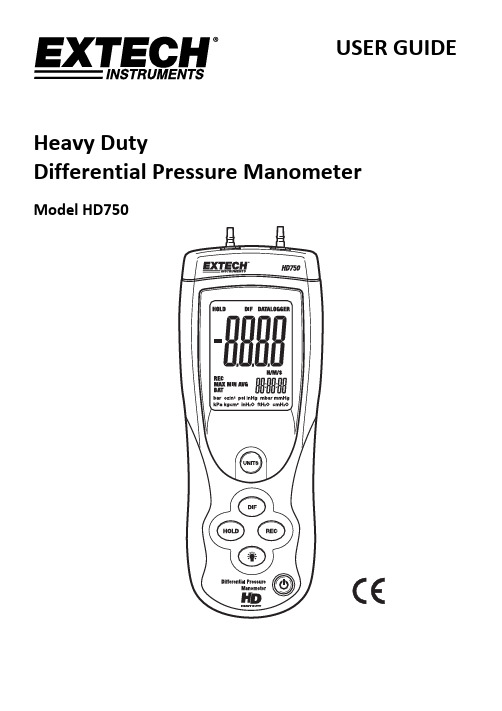
USER GUIDEHeavy DutyDifferential Pressure ManometerModel HD750IntroductionCongratulations on your purchase of the Extech Manometer Model HD750. This device measures gauge and differential pressure in the range of ±5.000 psi. The HD750 offers eleven (11) units of measure (user selectable by front panel pushbutton) and has a differential input that uses convenient quick‐disconnect fittings. Advanced features include DATA HOLD, MIN‐MAX‐AVG RECORD mode, ZERO/OFFSET, AUTO POWER OFF, and USB PC interface. This meter is shipped fully tested and calibrated and, with proper use, will provide years of reliable service. Please visit our website () to check for the latest version of this User Guide, Product Updates, and Customer Support.Meter Description1.P1 input2.AC adaptor jack3.P2Input4.LCD Display – Indicates the measurement data, unit of measure,elapsed timer, and function symbols as described in this manualB PC interface jack (3.5mm) – For use with data acquisitionsoftware6.UNIT button – Press to select the unit of measure7.DIF button– Press to display differential pressure. Also used toOFFSET the displayed readings.8.RECORD button– Press to access the MIN/MAX/AVG recordingmode9.HOLD / ZERO button– Press to freeze the displayed reading. Alsoused to zero the display (press and hold until display shows allzeroes).10.BACKLIGHT button – Press to switch the display backlight ON.The backlight will automatically turn OFF after 40 seconds.11.POWER button – Press to turn the meter ON or OFF12.Battery compartment (on rear)DisplayB data output active2.Differential Pressure Mode3.Data Hold Mode4.Primary display5.Record Mode6.MAX/MIN/AVG indicators7.Low Battery Indicator8.Pressure unit of measure9.Elapsed TimerBasic OperationMeter PowerThe HD750 uses a 9V battery for power. If the meter does not switch on when the POWER button is pressed or if the display shows BAT, replace the battery.When the POWER buttons is pressed, the meter performs a short self‐test and reverts to the settings in place when the meter was last turned off.Automatic Power‐off FeatureIn order to conserve battery life, the meter has an automatic power off feature (after 20 minutes). To defeat this feature, press and hold the HOLD button while turning the meter on. Release the HOLD button when ‘n’ appears on the display. The meter will now remain on until the user turns it off or until the battery weakens. Note that the Auto Power OFF feature will be reactivated the next time the meter is turned off and then on.Unit of MeasurePress the UNIT button to select the unit of measure. This meter offers eleven (11) units of measure as listed below.Unit of Measure Display iconPounds per square inch psiInches of Mercury inHgMilli‐bar mbarMillimeters of Mercury mmHgKilo‐Pascals kPaKilograms per centimeter squared Kgcm2Inches of water inH2OFeet of water ftH2OCentimeters of water cmH2OBars BarOunces per square inch ozin2Fittings ConnectionConnect tubing to the P1, P2 (or both) input port(s). If both inputs are used (differential mode), the meter displays a positive pressure reading if the P1 pressure is greater than P2 and a negative reading if P2 is greater than P1.Zero Adjust and Offset functionThe unit must be kept in the upright position when ZEROING or when taking measurements. To ZERO the meter: Before use and without fittings attached to the meter, press and hold the HOLD button for 3 seconds or until the display shows all zeroes.To OFFSET meter readings: Press the DIF button while taking a measurement. Subsequent readings will represent the difference between the current measurement and the measurement that was on the display when the DIF button was pressed.MIN‐MAX‐AVG Record Mode with Elapsed TimerThe RECORD function tracks the maximum (MAX), minimum (MIN), and average (AVG) readings with a time stamp. The elapsed timer is displayed on the lower right‐hand corner of the LCD and informs the user of the time a MAX or MIN reading was recorded.1.Press the RECORD button once. The REC indicator will appear on the display and thedisplayed elapsed timer will start (HH:MM:SS format [hours:minutes:seconds]).2.Press the RECORD button again to view the highest (MAX) reading recorded since theRECORD button was first pressed. The MAX indicator and maximum reading will appear on the display. The elapsed timer will show the time of the MAX event.3.Press the RECORD button again, the MIN indicator and the minimum value will appear onthe display. The elapsed timer will show the time of the MIN event.4.Press the RECORD button again, the AVG indicator and the average value will appear on thedisplay. The elapsed timer will continue to run.5.To return to normal operation, press and hold the RECORD button until the displayindicators REC, MAX, etc. switch off.Note that in the RECORD mode, the backlight and the power buttons are the only available functions.USB PC InterfaceThe meter has a built‐in USB port for use with the Manometer Data Acquisition software. The software allows the user to view, save, export, and print readings from the HD750. Refer to the documentation included with the software for complete details.Displayed Error CodesThe following codes are displayed when the meter encounters an error.ERR 1: Pressure input exceeds specified limitsERR 2: Pressure input is too low to readERR 3: The Differential Pressure input exceeds specified limitsERR 4: The Differential Pressure input is too low to readSpecificationsGeneral SpecificationsDisplay Four digit LCD with function indicatorsUnits of Measure BAR, mBAR, psi, kg/cm2, mm Hg, inches Hg, kPa, feet H2O, inchesH2O, cm H2O, and oz in2Accuracy ±0.3%FS (@ 25°C)Repeatability ±0.2% to 0.5% FSLinearity/Hysteresis ±0.3%FSCombined Accuracy ±1.1%FSMaximum Pressure 10psiResponse time 0.5s typicalInput circuit Differential inputs (P1 and P2)Input Ports Two metal 4.8mm, barbed for 1/8" (3.17mm) ID tubingData Hold Freezes displayed readingSensor Built‐in piezoelectric sensorsZero / Offset function Pushbutton activationSample rate 0.5 sec. (approx.)Compatibility Air or non‐corrosive and non‐ionized gas (not intended for use withliquids)Auto Power OFF Meter turns off after approx. 20 minutes to conserve energy (canbe deactivated)PC Interface Built‐in USB serial interfaceStorage conditions 0 to 60o C (14 to 140o F); < 80% RHOperating conditions 0 to 50o C (32 to 122o F); < 80% RHBattery power 9V alkaline battery (BAT low battery indicator)Battery life 125 hours typicalDimensions 210 x 75 x 50mm (8.2 x 2.9 x 1.9”)Weight 280g (9.8oz)Range SpecificationsRange/Units (Max.) Resolution± 0.344bar 0.001± 344.7mbar 0.1± 5.000psi 0.001± 0.351Kg/cm2 0.001± 258.5 mm Hg 0.1± 10.18 inches Hg 0.01± 34.47kPa 0.01± 11.53feet H2O 0.01± 138.3inches H2O 0.1± 351.5cm H2O 0.1± 80.00oz in2 0.01Battery ReplacementWhen the low battery indicator BAT appears on the display or if the meter does not switch on when the POWER button is pressed, it is necessary to replace the battery.To replace the battery:1.Open the battery compartment by sliding the meter’s rear panel in the direction of theembossed arrow.2.Replace the 9V alkaline battery3.Replace the battery compartment cover.All EU users are legally bound by the Battery Ordinance to return all used batteries tocommunity collection points or wherever batteries / accumulators are sold.Disposal in household trash or refuse is prohibited.Disposal: Follow the valid legal stipulations in respect of the disposal of the device at the end of its lifecycleOther Battery Safety Reminders∙Never dispose of batteries in a fire. Batteries may explode or leak.∙Never mix battery types. Always install new batteries of the same type.ConversionsUseful conversion FactorsFrom To Multiplierin of H2O in of Hg 0.07355in of H2O cm of H2O 2.54mm of Hg in of H2O 0.03937Copyright © 2013 FLIR Systems, Inc.All rights reserved including the right of reproduction in whole or in part in any formISO‐9001 Certified。
DPST-9200A 自动潜压速度测试设备说明书

DPST-9200A Automated Pitot Static Test Set “Exceeds RVSM High Accuracy Standards”FAA Certified Repair Station # DZMR112L Cage Code # 3PTA2Standard FeaturesGeneral InformationThe Model DPST-9200A Pitot Static Test Set is a precision flight line fully Automatic dual channel pressure controller, designed to provide regulated total (PT) pressure and static (PS) pressure outputs to simulatealtitudes and airspeed parameters. This test set can also be used in a laboratory environment to calibrateinstrumentation and other test equipment. A handheld remote terminal provides the operator full control oftest set functions while observing aircraft instruments such as Altimeters, Airspeeds / Mach Indicators and Rate of Climb Indicators.• Test set is equipped with quick connect fittings, 2 hoses (20 ft/ea) and a terminal cable (20 ft).Additional cable lengths are avaliable upon request.• Terminal specifications include user-friendly keypad interface; full-function Touch Screen; LED function indicators; Humidity, MIL-STD-810F, Method 507.4; and Water, IP67, sealed against immersion, MIL-STD-810F, Method 512.4, P-1.• Protection for instruments under test, includes a power failure protection feature, which in the event of an interruption to the electrical supply, locks the pneumatic system and allows safe depressurization to ambient ground conditions automatically without operator assistance.• Hoses have self-sealing quick connections to protect aircraft from pressure loss.• Vacuum and Pressure pumps are self contained with auto on/off pressure regulation.• Internal tanks hold pressures for quick start ups and high VSI performance rates.• Water resistance and temperature corrected sensors for extreme flight line conditions.• Exterior case dimensions 28”L x 14”W x 9”H / Weight 35lbs.• Certified to perform Reduced Vertical Separations Minimum or Standard FAR 91.411 Part 43 App E.• Precision microprocessor based with Honeywell sensors, accuracy to 0.001% of full range.• Calibration meets or exceeds the published specifications, which are traceable to the N.I.S.T.• The handheld remote terminal is sun-light readable color TFT display showing real instrument dial presentation.• The profiles feature allows standard setpoints of analtimeter or airspeed check to be downloaded froma computer. • Up to 50+ profiles can be stored in the system.• Automatic pitot and static leak rate functions and automatically calculate leak rate values.• “Go To Ground” feature automatically and safely depressurizes Pitot & Static pressure systems to ambient conditions.•Smart AC power supply for safe flight line usage input voltages range 85 to 265 V AC / 47 to 420 Hz.*Case meets required measurements to fit into overhead compartment incommercial airlines.Weight 35 lbs.DFW Instrument Corporation Tel # 214-217-7600 16445 Addison Road Fax # 214-217-8307 2nd Floor, Hangar 2 Toll Free # 888-500-0075 Addison, TX 75001 To buy, sell, rent or trade-in this product please click on the link below:/DFW-Instruments-DPST-9200A-Pitot-Static-Test-Set-RVSM-Digital.aspxAutomated RVSM Pitot Static Test Set DPST-9200A Performance SpecificationsAbsolute Pressure PerformanceStatic Pressure:Range: 0.3 to 40 inHg abs.Accuracy: +/- 0.001 % FS Repeatability: +/- 0.0008 % FSDrift: +/- 0.004 % FS per year max. Overpressure: 300 % FS without damagePitot Pressure:Range: 0.8 to 80 inHg abs.Accuracy: +/- 0.001 % FS Repeatability: +/- 0.002 +/- 100 ppm/yearDrift: +/- 0.01 % FS per year max. Overpressure: 300 % FS without damage Altitude PerformanceRange: -1,500 ft. to 55,000 ft. Resolution: 1 ft.Accuracy: ±2 ft. @ 0 ft., ±5 ft. @ 35,000 ft., and±12 ft. @ 55,000 ft.Rate of Climb PerformanceRange: 100 ft./min. to 12,000 ft./min. Resolution: 1 ft./min.Accuracy: ±1 % of rate with a min. of 10 ft./min. Static Range: 250 cubic inches maxPitot Range: 100 cubic inches max Airspeed PerformanceRange: 0 to 650 KnotsResolution: 0.1 KnotsAccuracy: ±0.5 Knots @ 20 knots±0.05 Knots @ 600 knotsMach PerformanceRange: 0.0 Mach to 2.791 Mach Resolution: 0.001 MachAccuracy: 0.01 Mach above 0.1 Machfor Ps = 29.921 InHg.EPR PerformanceRange: 0.1 to 3.0 (Ps @ 30inHg) Resolution: 0.001Accuracy: 0.05 % FS PSIPressure MediumDry AirPressure ConnectionsQuick Disconnects (2 ea.)Safety Seal on Female Quick Connect Display Update RateOnce Every 2 Tenths per SecondOutputsData Output / RS-485 / RS-485 (Option #1)SensorsHoneywell Certified Sensors (NIST Traceable) with built-in temperature compensationPower RequirementInput Range: 85 - 265 V AC Frequency Range: 47 Thru 420 HzEnvironmental SpecsTemp. Operating: -40° C to +85° C Temp. Storage: -25° C to +60° C Humidity: 0% to 95% RHWarranty & CalibrationWarranty: 2 years (parts & labor) Calibration: Up to 1 year (yearly calibration suggested)RVSM CertificationCalibration / Trace to NISTExceed RVSM Accuracy Compliance SpecsPhysical Dimensions22” L x 14” W x 9“HWeight Case35 Lbs. Storm Case/ YellowMIL-STD-810F • FED-STD-101C • ATA 300Accessories Include:Protection Quick Release Fittings, Hose Kit and Operation Manual.ORDERING INFORMATION/ OPTIONSMfg. Part Number:DPST-9200A-XXXXOption 1: RS-232/485 interface -RS Option 2: Rack mount -ROption 3: 28VDC power -DC Option 4: Encoder / Decoder -ENC Option 5: High Altitude (80K ft.) -HA Option 6: High Altitude -HA1K(99k ft./1050 knots/50k ROC)REV 01/28/11 DFW Instrument Corporation16445 Addison Road2nd Floor, Hangar 2Addison, TX 75001Tel. # 214-217-7600 Fax # 214-217-8307。
避雷器的残压之欧阳术创编
避雷器的残压避雷器的残压(Up):是指压敏电阻器两端所能承受的最高电压值,它表示在规定的冲击电流Ip通过压敏电阻时两端所产生的电压峰值。
(中华人民共和国国家标准GB18802.1-2002)通俗说:压敏型避雷器在冲击电流作用下,压敏电阻两端所产生的电压(Up)。
说明白了就是过电压来袭时,被保护设备承受的最高电压——前提避雷器没有损坏!在冲击电流下流过避雷器的压降,包括操作冲击残压和雷电冲击残压。
操作冲击残压是在操作冲击电流(我国取30/80µs)下流过避雷器的压降,它是避雷器对输变电设备的操作冲击保护水平。
雷电冲击电流(我国取8/20µs标准波,及1/5µs陡波,前者还用来区分避雷器等级,故称标称放电电流)下流过避雷器的压降称为雷电冲击残压,标准波下的残压与陡波下残压/1.15两者中的较大者为避雷器的雷电冲击保护水平。
如何控制避雷器的残压比,而残压是不是越小越好?压比控制一般是避雷器厂家电阻片制造水平决定的。
当然和电阻片直径有直接关系,一般在相同放电电流下,电阻片直径越大压比越低。
在需要时也可通过多柱并联降低压比(如特高压避雷器)。
当然直径越大、并联柱数越多的避雷器价格也越贵。
在实际应用中压比在现场是无法测量的,只能依靠厂家提供的数据。
(现场交接试验或预防性试验只能测量直流1mA参考电压,无法测量整只残压,当然一般谁也没有整只测量残压的能力,厂家也没有,只能是各片电阻片的残压累加值,或依据压比的换算值。
)所以有些厂家为了迎合客户的喜好,一味减低压比是虚假的。
另,残压理论上应越低越好!但如上所述不可能做到“很低”,氧化锌电阻片虽然是非线形的,但是总体还是随电流增大电压升高,不肯能做的和开关一样。
避雷器残压和系统绝缘配合有很大关系,是和被保护设备的绝缘水平有关系的。
可以看看新版GB11032里面写的很清楚。
没有必要一味追求低压比!避雷器的残压是避雷器的固有属性,是避雷器内部的阀片性能决定的。
BSY-187液化石油气残留物测定仪-说明书

SY/T 7509BSY-187液化石油气残留物测定仪使用说明书大连北港石油仪器有限公司一、概述本测定仪依据SY/T 7509标准设计制造,适用于测定液化石油气在37.8℃时挥发后残留物的含量。
本公司生产的液化石油残留物测定仪采用了国内独有的压缩机制冷式结构,外形独特新颖,控温精度高,降温迅速,操作方便,避免了国内现有同类仪器干冰,循环水降温所带来的外形繁复,操作困难等诸多不便,为国内目前最先进,便捷的液化石油气残留物测定仪。
如图一所示。
1、搅拌电机2、进样管3、出样管4、冷浴口5、离心管孔6、冷浴控温7、热浴控温8、仪器开关图一、BSY-187液化石油气残留物测定仪二、技术指标1、加热功率:1000W2、制冷功率:700W3、输入方式:Pt1004、输出方式:触发固态继电器5、控温精度:0.1℃6、温度范围:热浴:室温~50℃;冷浴:室温~-70℃7、工作电源:220V±10% 50HZ三、工作原理该仪器制冷系统是由压缩机、过滤器、毛细管节流器、蒸发器及各连接管路组成。
制冷剂通过蒸发器吸热膨胀,膨胀后的气体由压缩机压入排气管路形成高温高压气体再进入冷凝器冷却成液体,然后经毛细管节流降压进入蒸发器蒸发吸热从而达到制冷目的。
制冷剂蒸发后又被压缩机压入排气管进入冷凝器,这样周而复始地工作实现循环制冷。
温度控制系统是由智能数显控温仪进行PID调节实现定点控温,控温仪输出的控制信号触发固态继电器,使加热管工作抵消压缩机制冷系统产生的冷量,使其恒在我们所需要的温度上(见原理图)。
图二、液化石油气残留物测定仪原理图四、使用和维护本仪器开箱后,请先进行外观检查,各部分情况正常后,再进行以下工作。
先将水注入热浴内,再将乙醇(参照SY/T7509)注入冷浴内。
接好电源,打开“电源”开关,此时分别显示浴内温度。
1、开启电源开关,开启搅拌开关,搅拌浆均匀搅拌。
仪器出厂时,热浴控温点设定为38℃,冷浴控温点设定为-55℃。
- 1、下载文档前请自行甄别文档内容的完整性,平台不提供额外的编辑、内容补充、找答案等附加服务。
- 2、"仅部分预览"的文档,不可在线预览部分如存在完整性等问题,可反馈申请退款(可完整预览的文档不适用该条件!)。
- 3、如文档侵犯您的权益,请联系客服反馈,我们会尽快为您处理(人工客服工作时间:9:00-18:30)。
ZDZK-III(C)-1电脑转速测控仪使用说明书四川中鼎自动控制有限公司地址:成都市武兴四路11-13号电话:(028)85080508传真:(028)85090402邮编:610041主要技术性能测量信号路数:两路,①齿盘传感器(DZK-C-1)或永磁机频率Ma(DZK-III-1)②发电机频率Pt测频范围: 1~100Hz 齿盘输入中心频率可有25Hz、50Hz、100Hz三种选择。
输入电压: 0.3~250VAC测量精度: 0.1%±1字数显内容:机组频率,发电机频率,转速百分数,转速百分数最大值,各路输出整定值输出信号: 8路,1-6点(J1-J6)输出常开触点,初值为中心转速的5%ne、15%ne、50%ne、80%ne,95%ne、140%ne。
第1、2点为小于等于设定值闭合,第3-6点为大于等于设定值闭合,有1Hz的回差值。
每点可由用户在所定范围内设定。
第6点为机组过速保护输出,有两对触点输出。
第7点(J N)为扩展控制输出,为一组转换接点,动作值可在全量程范围内设置,可选择设置是大于设定值动作或小于设定值动作。
第8点(J W)为报警输出常闭触点,机组正常工作时触点断开,在仪器失电;传感故障;机组惰转时,触点闭合,发出报警信号。
标准模拟量输出:对应于机组转速0%~200%,输出4~20mA电流输出接点容量: 5A/250VAC,0.5A/220VDC最大值记忆:能记忆显示转速最大值n M%,可由用户清除。
工作环境:温度 0~50℃,湿度 <85%外形尺寸:盘装 160×80×250mm工作方式:连续工作电源:交直流两用85V~260V功耗: 8W一概述DZK系列电脑转速测控仪经历十年的应用与改进,已成功应用于全国数百个水力发电厂,获得用户一致好评。
DZK-C-1和 DZK-III-1在原有DZK系列电脑转速测控仪功能上又作了重大改进,使功能更齐全、性能更可靠。
主要改进有:1、连接端子全用进口菲尼克斯端子。
2、主机芯片采用工业级美国CYGNAL第三代单片机。
3、电源采用交直流两用模块85V-260V宽工作范围。
4、增加报警功能和扩展了控制出口接点。
5、过速出口采用双接点,可同时送到控制回路和监控回路。
6、4~20mA输出可对应两路输入信号中的任何一路。
电脑转速测控仪除取代机组转速继电器外,同时兼有双路测量频率、机组转速百分比(或实际转速)、机组甩负荷及过速试验最大转速记忆等功能的新一代机组自动化测控仪表,被东方电机股份有限公司、东风电机厂,重庆水轮机厂,四川电器厂、阿城继电器厂、水电部成都勘测设计研究院、四川水利水电设计研究院和省内外数百个水电厂所选用,获得一致好评,达到了国内先进水平。
该测控仪充分利用单片微机的特长,实现了精度高、功能强、高可靠、易操作等优点。
其最突出的特点在于只与测量信号的频率有关而与信号电压幅值无关,特别适合低残压信号的测量。
它集频率表、转速表、转速继电器、转速测试仪表于一体。
由于其测控精度由晶振决定,转速接点出口值不会因长期运行而发生变化,提高了可靠性。
该测控仪还能保存记忆当前机组转速最大值,这给机组甩负荷试验,事故过速分析带来了莫大的方便。
采用永磁机、发电机电压互感器两路残压测频,扩宽了测量范围。
测控仪采用回差方式消除出口继电器的抖动。
对于机组刹车引起的波形畸变,则采用闭锁方式防止输出误动作。
根据电厂运行需要,可以在现场方便地对6个转速出口值进行一定范围的整定。
该转速测控仪还具有标准电流输出,可以方便地与计算机接口,可作为水电厂全厂计算机监控系统的组成部分。
测控仪采用标准槽形表结构,安装十分方便,塑壳面罩美观实用。
二工作原理1.CPU系统采用美国CYGNAL工业级单片机。
晶振6M,经内部分频后产生测量定时脉冲,周期为2μs,其测量精度可达0.01Hz,稳定性高,长期不变。
2.显示电路采用静态显示方案,亮度高,只用2个按键操作,方便易学。
3.信号测量电路有隔离、放大、整形功能。
两路信号完全独立,与仪器内无电联系。
在0.3V~250V范围内的输入信号能长期可靠工作,300V以内也能短期工作。
仪器将信号周期取入计算机内,再换算成对应的频率、转速、转速百分比及最大值等内容提供显示、记忆。
4.8路输出信号经过放大后驱动继电器输出,第1-6点(J1-J6)动作值与所设定的转速百分比对应,实测转速达到设定值时,对应输出接点动作。
实现功能与老产品相同。
第7点(J N)为扩展接点,可由用户在测量范围内任意设置控制值。
输出是一对转换触点,可设置为大于或小于设定值动作。
报警输出(J W)功能的增加,可对多种异常情况发出报警信号,提醒值班人员及时发现和处理。
5.监控电路能对仪器内部的工作情况进行监控。
当上电、掉电或电压不稳定时,能保护计算机中的信息。
当出现意外死机时,能自动产生复位信号重新启动计算机工作,大大提高了仪器的可靠性。
6.为提高测控仪的可靠性,电源单元采用交直流两用宽电压范围的电源模块,可直接使用厂用直流控制电源。
也可由交流供电。
工作范围85V~260V。
三面板说明①.四位数码管,显示参数。
②.性质指示灯,每灯亮分别指示数码管当前显示内容。
fc:表示齿盘工作频率(若DZK-Ⅲ-1则为fm,表示永磁机输入频率)fp:表示P T信号频率。
n %:显示转速百分比。
n m%:显示转速百分比最大值。
设置:进入设置操作状态。
③.输出指示灯,灯亮指示对应输出继电器动作。
第1、2点为输入信号频率小于设定值闭合,第3~6点为大于设定值闭合。
第n点是供用户灵活设置的点,灯亮表示继电器动作。
它可根据参数的设置不同,执行小于或大于设定值工作。
第2点用于控制刹车,为防止振动引起的信号畸变使仪器误动作,在输入频率自上往下降至第2点灯亮后。
仪器将闭锁第3~6点的输出,直到频率消失或降为零,才对第3~6点解锁。
④.报警指示灯有两种:1.被测信号突然消失,仪器会自动切换到另一输入回路工作,报警继电器发出报警信号,同时面板上“传感报警”灯亮,报警灯亮的情况下,按一下“置清”键,可清除报警。
2.机组在停机情况下,若发生惰转,报警继电器发出报警信号,同时面板上的“惰转报警”指示灯亮。
按一下“置清”键可清除报警。
⑤.过速记忆灯:当转速≥第6点设定值时,灯亮并保持,记忆最大值。
在n m%灯亮时按“置清”键才会熄灭,同时清除最大值。
⑥.“置清”键:设置参数时,用于置数。
报警灯和过速记忆灯亮时,用于清除。
⑦.“转换”键:用于转换显示的参数内容。
四背板说明端子接线说明:A1,A2:为仪器工作电源,交直流两用,电压范围85V~260V。
本仪器无电源开关,电源接上以后便长期连续运行。
应接好线后再送电。
A3:接大地,此端子内部与机壳相连。
A4,A5:P T信号,接入电压互感器信号。
为防干扰尽可能用双绞屏蔽线接入测量信号。
DZK-Ⅲ-1型若只用1路输入测量信号(Ma或P T),应将两输入口并联使用。
即将信号线一路接A4,A6。
另一信号线接A5,A7。
信号电压幅度应在0.3V~250V范围内。
A6,A7,A8:DZK-C-1型为齿盘传感器输入端。
测速传感器为三线制NPN型。
尽可能使用屏蔽线接入测量信号。
PT信号也应接入。
实际测量时以齿盘测量为主,P T信号为辅。
若DZK-Ⅲ-1型,将Ma永磁机信号接入到A6,A7。
信号电压幅度应在0.3V~250V范围内。
A9,A10(I O+,I O-):模拟量输出信号,4~20mA对应机组转速的0~100Hz。
用户将电流信号转换成电压信号时,建议使用250Ω标准电阻。
A11,A12:报警继电器J W常闭触点,故障报警。
有三种故障该触点都会闭合,即发生传感故障,惰转故障,仪器失电故障。
仪器正常工作时,触点断开。
A13,A14,A15:扩展继电器JN的一对转换接点。
可在中心转速的1%~170%范围内设置控制点。
小于等于闭合或大于等于设定值闭合。
A16,A17:第1点输出继电器J1常开触点,设置参数范围1%~25%转速。
小于等于设定值闭合。
B1,B2:第2点输出继电器J2常开触点,设置参数范围10%~40%转速。
小于等于设定值闭合。
B3,B4:第3点输出继电器J3常开触点,设置参数范围40%~95%转速。
大于等于设定值闭合。
B5,B6:第4点输出继电器J4常开触点,设置参数范围70%~95%转速。
大于等于设定值闭合。
B7,B8:第5点输出继电器J5常开触点,设置参数范围90%~120%转速。
大于等于设定值闭合。
B9,B10:第6点输出继电器常开触点J6-1,设置参数范围130%~170%转速。
大于等于设定值闭合。
B11,B12:第6点输出继电器常开触点J6-2,可将过速信号分别送到两个回路中去。
以上各点动作值闭合到断开都有1Hz的回差,每点动作后要停留1秒钟,下一步才能动作。
设置各点控制参数时,应从小到大按顺序。
可以将两点设为相同参数。
五操作说明序号数码管性质灯说明1 ○○.○○fm 亮永磁机频率2 ○○.○○fp 亮发电机频率,无测量信号。
fm fp灯交替闪亮3 ○○.○○ne% 亮转速百分比4 ○○.○○nm% 亮转速最大值。
按【置清】键可清除该值和过速记忆灯5 ——0 灭按【置清】键可在0和9之间变化。
非“8”数字时按【显转】键回到序号1。
“8”数字时按【显转】键进入序号6~126 1.005 设置灯亮第1输出点。
按【置清】键,数在1—25%之间变化7 2.035 设置灯亮第2输出点。
按【置清】键,数在10—40%之间变化8 3.080 设置灯亮第3输出点。
按【置清】键,数在40—95%之间变化9 4.095 设置灯亮第4输出点。
按【置清】键,数在70—95%之间变化10 5.115 设置灯亮第5输出点。
按【置清】键,数在90—120%之间变化11 6.140 设置灯亮第6输出点。
按【置清】键,数在130—170%之间变化12 E.000 设置灯亮第N输出点。
按【置清】键,数在1—170%之间变化13 E.- - 0 设置灯亮第N输出点动作选择。
按【置清】键,数在0,1之间变化。
当设置为0时,≤设定值继电器吸合,为1则≥设定值吸合。
1.仪器上电后显示序号1内容,若两输入回路都无信号,则在序号1、2之间交替。
按【显转】键,显示内容在序号1至序号5依次循环。
2.序号1~4显示的是被测的频率值,转速值,最大值。
无论显示哪项内容,输出控制都正常工作。
3.序号5是选择项,只有用户需要查阅或修改该控制参数时,才在该序号通过【置清】键将显示置为8,再按【显转】键进入序号6~13,若为非数字8,按【显转】键便返回到序号1。
4.序号6~13是控制参数值。
第一次进入显示的是出厂初值,用户可在线修改控制参数,一经修改就一直保存,直到用户下次修改。
