路由器双出口负载分担并NAT及互为备份
H3C AR 18-21路由器快速配置

H3C AR 18-21路由器产品介绍H3C AR 18-21路由器是华为3Com公司开发的新一代专业的宽带路由器,它将路由和交换设备有机地结合在一起,为中小企业和网吧提供交换及接入的一体化解决方案。
AR 18-21宽带路由器采用全新的硬件和软件平台,具备更高的数据转发性能和数据加密性能,并且其4个交换网口支持VLAN划分。
该产品功能特性丰富,并支持Web网管、端口镜像等特性,AR 18-21宽带路由器是中小企业和网吧等用户的理想选择。
产品特点多WAN口(1-3个WAN口),支持负载分担和端到端线路检测的备份机制(Auto-detect)高处理性能,CPU主频从200M到400M,带机数量高支持端口镜像、Web网管、DDNS和防BT等功能特征交换端口支持VLAN划分,带S的机型支持硬件加密功能◆路由和交换一体化AR 18-21路由器产品支持4个不等的交换以太网接口,这是一种典型的路由器集成交换机的路由交换一体化产品,特别适合中小企业、企业分支机构和网吧等的综合应用组网。
18-21有4个10/100M以太网交换端口,这些产品的交换端口均支持VLAN的划分,可以满足大多数中小企业的组网及隔离不同业务的要求。
用户只需一台交换路由器,无需购买交换机设备,便可实现多用户接入Internet,节约用户网络建设的费用、增强用户应用的方便性。
AR 18-21具有1个10/100M以太网WAN接口,可实现单出口线路的通信。
这完美地解决了中小企业和网吧用户实现双线路或多线路的通信接入中的负载分担和备份的问题。
◆VPN解决方案AR 18-21路由器集成了VPN网关的功能,通过在路由器上面建立VPN隧道,可以将远程分支机构通过Internet安全、廉价地接入总部网络。
因此对于有大量分支机构需要接入总部的企业,可以用VPN技术来代替昂贵的专线接入。
支持L2TP VPN、GRE VPN、IPSec VPN,轻松的实现企业的各种类型的VPN接入要求。
H3C双线出口配置
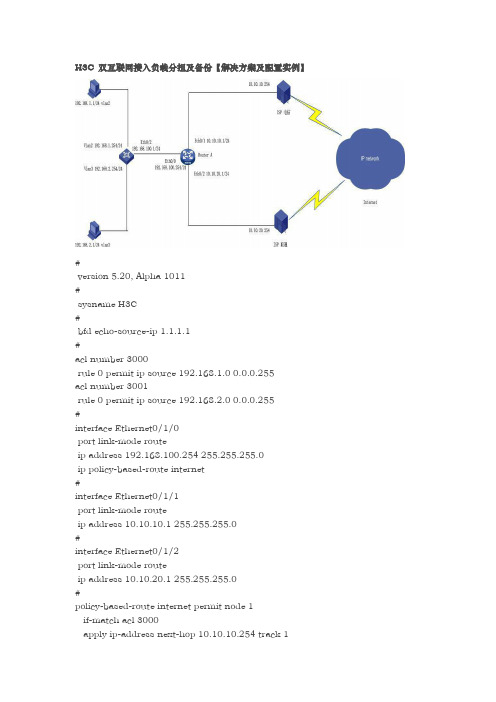
H3C 双互联网接入负载分担及备份【解决方案及配置实例】#version 5.20, Alpha 1011#sysname H3C#bfd echo-source-ip 1.1.1.1#acl number 3000rule 0 permit ip source 192.168.1.0 0.0.0.255acl number 3001rule 0 permit ip source 192.168.2.0 0.0.0.255#interface Ethernet0/1/0port link-mode routeip address 192.168.100.254 255.255.255.0ip policy-based-route internet#interface Ethernet0/1/1port link-mode routeip address 10.10.10.1 255.255.255.0#interface Ethernet0/1/2port link-mode routeip address 10.10.20.1 255.255.255.0#policy-based-route internet permit node 1if-match acl 3000apply ip-address next-hop 10.10.10.254 track 1policy-based-route internet permit node 2if-match acl 3001apply ip-address next-hop 10.10.20.254 track 2#ip route-static 0.0.0.0 0.0.0.0 10.10.10.254 track 1ip route-static 0.0.0.0 0.0.0.0 10.10.20.254 track 2ip route-static 192.168.0.0 255.255.0.0 192.168.100.1#track 1 bfd echo interface Ethernet0/1/1 remote ip 10.10.10.254 local ip 10.10.10.1track 2 bfd echo interface Ethernet0/1/2 remote ip 10.10.20.254 local ip 10.10.20.1配置案例1.10 双WAN接入路由配置目前越来越多的企业和网吧采用双WAN上行接入的方式,这种组网方式既可以实现链路的负载分担又可以实现链路的动态备份,受到用户的普遍欢迎。
路由器实现网络负载均衡的三种模式

路由器实现网络负载均衡的三种模式“负载均衡”概念运用在网络上,简单来说是利用多个网络设备通道均衡分担流量。
就像是寺庙一天要挑10桶水,1个尚必需要走10趟,但同时指派10个和尚却只要一趟即可完成工作的道理一样。
负载均衡可运用多个网络设备同时工作,达成加速网络信息的处理能力,进而优化网络设备的性能,取代设备必须不停升级或淘汰的命运。
目前普遍被运用在网络设备中,如服务器、路由器、交换机等。
目前提出的三种不同的负载均衡模式,可较全面的包含各种网络架构中所应采取措施,三种模式分别是:模式一:智能型负载均衡智能型负载均衡模式,是依据接入WAN端带宽的大小比例,自动完成负载均衡工作,进一步协助达成带宽使用率的优化目的。
Qno侠诺在智能型负载均衡模式中,提供了联机数均衡与IP均衡两种选择。
联机数均衡是依据WAN端带宽大小比例,将内网所有的联网机数作均衡分配。
例如WAN1接入4M、WAN2接入2M,则联机数就会依据2:1分配。
此种配置是网管员最一般的配置模式。
而IP均衡模式是为了避免某些网站(EX银行网站或HTTPS类型的网站),只能接受来自同一个公网IP的所发出封包的瓶颈。
如果采用联机数负载均衡模式,会发生该IP所发出的访问封包不一定是从固定WAN口流出,造成特定网站拒绝服务,导致断线的情况发生。
如果采用IP均衡,让IP依据WAN端带宽大小进行比例均衡分配,例如WAN1与WAN2的带宽比例为2:1,则PC1、PC2走WAN1,PC3走WAN2,PC4、PC5走WAN1……,即可达到同一个内网PC 所发出的应用服务封包,都从固定的WAN口(公网IP)流出,而整体内网IP也会依据带宽大小比例,自动进行均衡配置。
此种配置比较适合常常需要进入特定网站时选择。
模式二:指定路由指定路由比起智能型负载均衡而言,是保留了更多的自由设定弹性与例外原则。
由于智能型负载均衡是针对整体内网联机数或是整体IP进行均衡分配。
并不能个别指定某种应用服务、某个特定IP、某个特定网址,通过哪个WAN口出去。
电信、移动网络双出口解决方案

电信、移动网络双出口解决方案网络双出口解决方案在这互联网时代,信息数据的传输至关重要,这时网络连接的可靠性对一个企业而言将尤为重要,而我们一般企业现有的都是单线路(链路)连接生产网络就变得不那么给力,一旦线路故障,整个业务就瘫痪了,这将严重地影响了一个企业的生产经营。
这时我们就应该考虑来解决单线路所面临的问题。
面对双线路的几种解决方案,应该如何在解决方案中选择将是接下来我们要谈论的。
一、传统的主备线路解决方案这是ICG网关打造了双出口网络:1. 电信线路为主线路,出口IP为6.16.5.6;2. 移动线路为备线路,出口IP为2.17.1.24;3. 对内连接4台PC,分别是PC1—PC4,ICG连接这些PC的内部VLAN地址是192.168.1.1。
主备线路解决方案是最容易实现的:1. 电信出口默认路由优于移动出口默认路由,因此在电信线路连接正常情况下,所有PC都是从电信线路访问生产网络;2. 当电信线路发生故障,那么电信出口默认路由失效,移动出口默认路由生效,所有PC切换到移动线路访问生产网络。
如上图所示,电信线路故障,所有PC都从移动线路访问生产网络。
这种方案虽然可行,但是,因为这2条线路在同一时刻只能使用1条,而我们将要同时为2条线路付费的,同时使用2条线路又不能增加带宽来获得更完美的带宽体验。
所以我们对传统解决方案将需要改进,我们需要让传统解决方案变得更紧实一些。
二、让2条线路都用起来的解决方案——等价路由在传统的解决方案中,电信、移动两条默认路由是不等价的,而是主备,电信的优于移动,如果要让2条线路都用起来,那么我们很容易想到使用等价路由,即电信、移动的默认路由是一视同仁的,选择谁做出口都一样,这个看起来的确要比传统解决方案要好一点。
在ICG网关正确的调度下,这2条链路的确都可以利用起来,而且流量可以近似于平分秋色,那这么做是不是就可以达到我们所期望的呢?我不得不说,选择这项解决方案可能过不久又会面临很多问题,有些页面会打不开,这时还不如用传统解决方案呢。
负载分担方式

负载分担方式
负载分担方式主要是为了在多台路由器中避免设备闲置,同时提高网络可靠性。
常见的负载分担方式有以下几种:
1.流式负载分担:在能够实现快速转发功能之后,只能进行流式负载分担。
举例来说,当前设备上存在两个等价路由,如果其中一个数据流通过,则会从其中一个进行转发;如果其中一个数据流通过,则会分别转发这两个等价路由。
2.负载分担:在快速转发功能关闭后,进行基于报文的负载分担,将待发送的报文平均分配到两个等价路由上。
3.负载分摊基于带宽:在快速转发功能关闭时,消息按接口物理带宽进行负载分摊(即基于消息的负载分摊);在用户为该接口配置了指定的负载带宽时,设备按用户指定的接口带宽进行负载分摊,即按照接口物理带宽的比例关系进行分配。
4.基于报文内容进行负载分担:在多台路由器上建立不同的备份组,每个备份组中包括一个主用路由器和若干个备用路由器,主用路由器不一定要相同。
在备份组内的路由器根据优先级不同可以分别担任主用和备用角色。
这种方式简化了主机的配置,同时可以在某台路由器出现故障时仍然提供高可靠的缺省链路,有效避免单一链路发生故障后网络中断的问题。
双wan口路由器工作原理

双wan口路由器工作原理
双WAN口路由器是一种网络设备,它具有两个WAN口(Wide Area Network,广域网口),可以连接到两个不同的互联网服务提供商(ISP)或者同一个ISP的不同连接。
双WAN口路由器的工作原理涉及到负载均衡和容错备份两个主要方面。
首先,让我们来看看负载均衡的工作原理。
当双WAN口路由器接收到网络数据时,它会根据预先设定的策略,将数据流量分配到不同的WAN口上。
这样可以实现对网络流量的分流,从而达到负载均衡的效果。
负载均衡可以使网络流量在多个连接之间均匀分布,避免某一条线路过载,提高整体网络的稳定性和性能。
其次,双WAN口路由器还具备容错备份的功能。
如果其中一个WAN口的连接出现故障或者断开,路由器可以自动切换到另一个可用的WAN口,确保网络连接的可靠性和稳定性。
这种容错备份的机制可以保证即使一个连接出现问题,网络服务仍能够继续运行,提高了网络的可用性。
另外,双WAN口路由器通常还具有智能流量管理功能,可以根据网络流量的特点和需求,对数据进行优化和调度,提高网络的利
用率和性能。
此外,双WAN口路由器还可以支持虚拟专用网络(VPN)功能,实现远程访问和安全通信等应用。
总的来说,双WAN口路由器通过负载均衡和容错备份的机制,
实现了对多个网络连接的有效管理和利用,提高了网络的可靠性、
稳定性和性能。
这种路由器在企业和需要高可用性网络的场合具有
重要的应用意义。
双ISP配置实验:包括负载均衡+冗余备份

如果要实现去往目标 192.168.1.0 /2.0 /3.0 通过接口 200.200.2.254 出去,其余流量负载均衡配置如下: ip route 192.168.1.0 255.255.255.0 200.200.2.254 ip route 192.168.2.0 255.255.255.0 200.200.2.254 ip route 192.168.3.0 255.255.255.0 200.200.2.254 ip route 0.0.0.0 0.0.0.0 200.200.2.254 ip route 0.0.0.0 0.0.0.0 200.200.1.254 注意此种配置方法,如果 200.200.2.254 被 shutdown 的话,前面 5 条静态路由能够自动消失 ,从而所有流量通过 200.200.1.254 出去,反之,200.200.1.254 被 shutdown 的话,所有流量通过 200.200.2.254 出去。
192.168.0.5 DHCP server udp 67
配置方法
ip nat inside source static udp 192.168.0.1 23 200.200.8.252 23 extendable
ip nat inside source static tcp 192.168.0.3 80 200.200.8.252 80 extendable
ip nat inside source static tcp 192.168.0.5 67 200.200.8.252 67 extendable 有通信流量之后
RACK02R2#show ip nat t
Pro Inside global
Inside local
路由器双出口负载分担并NAT及互为备份

思科路由器双WAN口负载分担并NAT及互为备份说明:客户接入ISP1及ISP2,内部有4 个网段分别是:192.168.10.0/24192.168.20.0/2410.10.10.0/2420.20.20.20/24正常模式为192.168.10.0和10.10.10.0两个网段优先走ISP1,192.168.20.0和202.20.20.0两个网段优先走ISP2。
当IPS1线路中断时(即使R3接IPS1的接口是UP)192.168.10.0和10.10.10.0两个网段会自动转到ISP2,ISP2中断时同亦。
下面是拓扑图,及各台设备的配置文档,在GNS3上模拟测试成功。
(在网络上一直是伸手党,现在也分享下自己的经验,有不当之处还请指教,谢谢)分别在R1、R2均配置loopback 0 1.1.1.1/32为测试对象,R3为边界路由器,配置最多放在最后R1R1#sh runBuilding configuration...Current configuration : 761 bytes!version 12.4service timestamps debug datetime msecservice timestamps log datetime msecno service password-encryption!hostname R1!boot-start-markerboot-end-marker!!no aaa new-model!!ip cefno ip domain lookup!!interface Loopback0ip address 1.1.1.1 255.255.255.255!interface FastEthernet0/0ip address 11.11.11.3 255.255.255.248duplex autospeed auto!interface FastEthernet0/1no ip addressshutdownduplex autospeed auto!ip route 11.11.11.0 255.255.255.248 11.11.11.1 !no ip http serverno ip http secure-server!control-plane!gatekeepershutdown!!line con 0exec-timeout 0 0logging synchronousstopbits 1line aux 0stopbits 1line vty 0 4!endR2R2#sh runBuilding configuration...Current configuration : 761 bytes!version 12.4service timestamps debug datetime msecservice timestamps log datetime msecno service password-encryption!hostname R2!boot-start-markerboot-end-marker!!no aaa new-model!!ip cefno ip domain lookup!!interface Loopback0ip address 1.1.1.1 255.255.255.255!interface FastEthernet0/0ip address 22.22.22.3 255.255.255.248duplex autospeed auto!interface FastEthernet0/1no ip addressshutdownduplex autospeed auto!ip route 22.22.22.0 255.255.255.248 22.22.22.1 !no ip http serverno ip http secure-servercontrol-plane!gatekeepershutdown!!line con 0exec-timeout 0 0logging synchronousstopbits 1line aux 0stopbits 1line vty 0 4!endR4R4#SH RUNBuilding configuration...Current configuration : 755 bytes!version 12.4service timestamps debug datetime msec service timestamps log datetime msec no service password-encryption!hostname R4!boot-start-markerboot-end-marker!!no aaa new-model!!ip cefno ip domain lookup!!!!!!!!!!!!!!!!!!!!!!!interface Loopback0ip address 10.10.10.10 255.255.255.0 !interface FastEthernet0/0ip address 192.168.10.10 255.255.255.0 duplex autospeed auto!interface FastEthernet0/1no ip addressshutdownduplex autospeed auto!ip route 0.0.0.0 0.0.0.0 192.168.10.1 !no ip http serverno ip http secure-server!!!!!!control-plane!!!!!!gatekeepershutdown!!line con 0exec-timeout 0 0logging synchronousstopbits 1line aux 0stopbits 1line vty 0 4!!endR5R5#SH RUNBuilding configuration...Current configuration : 757 bytes!version 12.4service timestamps debug datetime msec service timestamps log datetime msec no service password-encryption!hostname R5!boot-start-markerboot-end-marker!!no aaa new-model!!ip cefno ip domain lookup!!!!!!!!!!!!!!!!!!!!!!!interface Loopback0ip address 20.20.20.20 255.255.255.0 !interface FastEthernet0/0ip address 192.168.20.20 255.255.255.0 duplex autospeed auto!interface FastEthernet0/1no ip addressshutdownduplex autospeed auto!ip route 0.0.0.0 0.0.0.0 192.168.20.254 !no ip http serverno ip http secure-server!!!!!control-plane!!!!!!gatekeepershutdown!!line con 0exec-timeout 0 0logging synchronousstopbits 1line aux 0stopbits 1line vty 0 4!!endR6R6#SH RUNBuilding configuration...Current configuration : 1548 bytes!version 12.4service timestamps debug datetime msec service timestamps log datetime msec no service password-encryption!hostname R6!boot-start-markerboot-end-marker!no aaa new-model!resource policy!memory-size iomem 5ip cef!!!!no ip domain lookup!!!!!!!!!!!!!!!!!!!!!!!interface FastEthernet0/0 no ip addressshutdownduplex autospeed auto!interface FastEthernet0/1 no ip addressshutdownduplex autospeed auto!interface FastEthernet1/0switchport mode trunk!interface FastEthernet1/1!interface FastEthernet1/2!interface FastEthernet1/3!interface FastEthernet1/4switchport access vlan 10!interface FastEthernet1/5switchport access vlan 20!interface FastEthernet1/6!interface FastEthernet1/7!interface FastEthernet1/8!interface FastEthernet1/9!interface FastEthernet1/10!interface FastEthernet1/11!interface FastEthernet1/12!interface FastEthernet1/13!interface FastEthernet1/14!interface FastEthernet1/15!interface Vlan1no ip address!interface Vlan10ip address 192.168.10.254 255.255.255.0 !interface Vlan20ip address 192.168.20.254 255.255.255.0!ip route 0.0.0.0 0.0.0.0 192.168.10.1ip route 10.10.10.0 255.255.255.0 192.168.10.10 ip route 20.20.20.0 255.255.255.0 192.168.20.20 !!no ip http serverno ip http secure-server!!!!!!!control-plane!!!!!!!!!!line con 0exec-timeout 0 0logging synchronousline aux 0line vty 0 4!!webvpn context Default_contextssl authenticate verify all!no inservice!!endR6#R3R3#SH RUNBuilding configuration...Current configuration : 2739 bytes!version 12.4service timestamps debug datetime msecservice timestamps log datetime msecno service password-encryption!hostname R3!boot-start-markerboot-end-marker!!no aaa new-model!!ip cefno ip domain lookup!!ip sla monitor 1type echo protocol ipIcmpEcho 11.11.11.3 source-interface FastEthernet0/0 frequency 10ip sla monitor schedule 1 life forever start-time nowip sla monitor 2type echo protocol ipIcmpEcho 22.22.22.3 source-interface FastEthernet0/1 frequency 10ip sla monitor schedule 2 life forever start-time now!!!!!!!!!!!!!!!!track 1 rtr 1 reachability!track 2 rtr 2 reachability!!!!!interface FastEthernet0/0ip address 11.11.11.1 255.255.255.248 ip nat outsideip virtual-reassemblyduplex autospeed auto!interface FastEthernet0/1ip address 22.22.22.1 255.255.255.248 ip nat outsideip virtual-reassemblyduplex autospeed auto!interface FastEthernet1/0no ip addressshutdownduplex autospeed auto!interface FastEthernet1/1no ip addressshutdownduplex autospeed auto!interface FastEthernet2/0no ip addressduplex fullinterface FastEthernet2/0.10encapsulation dot1Q 10ip address 192.168.10.1 255.255.255.0ip nat insideip virtual-reassemblyip policy route-map test!ip route 0.0.0.0 0.0.0.0 11.11.11.3ip route 0.0.0.0 0.0.0.0 22.22.22.3ip route 10.10.10.0 255.255.255.0 192.168.10.254ip route 20.20.20.0 255.255.255.0 192.168.10.254ip route 192.168.20.0 255.255.255.0 192.168.10.254!no ip http serverno ip http secure-server!ip nat inside source route-map 1 interface FastEthernet0/0 overload ip nat inside source route-map 2 interface FastEthernet0/1 overload ip nat inside source route-map 3 interface FastEthernet0/1 overload ip nat inside source route-map 4 interface FastEthernet0/0 overload !access-list 10 permit 192.168.10.0 0.0.0.255access-list 10 permit 10.10.10.0 0.0.0.255access-list 20 permit 192.168.20.0 0.0.0.255access-list 20 permit 20.20.20.0 0.0.0.255!route-map test permit 10match ip address 10set ip next-hop verify-availability 11.11.11.3 1 track 1set ip next-hop verify-availability 22.22.22.3 2 track 2!route-map test permit 20match ip address 20set ip next-hop verify-availability 22.22.22.3 1 track 2set ip next-hop verify-availability 11.11.11.3 2 track 1!route-map 1 permit 10match ip address 10match interface FastEthernet0/0!route-map 2 permit 10match ip address 20match interface FastEthernet0/1route-map 3 permit 10 match ip address 10 !route-map 4 permit 10 match ip address 20 !!!!control-plane!!!!!!gatekeepershutdown!!line con 0exec-timeout 0 0logging synchronous stopbits 1line aux 0stopbits 1line vty 0 4!!endR3#。
静态路由实现路由负载分担主备备份案例

静态路由实现路由负载分担/主备备份案例本文以华为设备为例静态路由简介静态路由是一种需要管理员手工配置的特殊路由。
静态路由比动态路由使用更少的带宽,并且不占用CPU资源来计算和分析路由更新。
但是当网络发生故障或者拓扑发生变化后,静态路由不会自动更新,必须手动重新配置。
静态路由有5个主要的参数:目的地址和掩码、出接口和下一跳、优先级。
使用静态路由的好处是配置简单、可控性高,当网络结构比较简单时,只需配置静态路由就可以使网络正常工作。
在复杂网络环境中,还可以通过配置静态路由改进网络的性能,并且可以为重要的应用保证带宽。
配置注意事项一般情况下两个设备之间的通信是双向的,因此路由也必须是双向的,在本端配置完静态路由以后,请不要忘记在对端设备上配置回程路由。
在企业网络双出口的场景中,通过配置两条等价的静态路由可以实现负载分担,流量可以均衡的分配到两条不同的链路上;通过配置两条不等价的静态路由可以实现主备份,当主用链路故障的时候流量切换到备用链路上。
静态路由实现路由负载分担组网需求如图1所示,PC1和PC2通过4台Switch相连,从拓扑图中可以看出,数据从PC1到PC2有两条路径可以到达,分别是PC1-SwitchA-SwitchB-SwitchC-PC2和PC1-SwitchA-SwitchD-SwitchC-PC2,为了有效利用链路,要求从PC1到PC2的数据流平均分配到两条链路上,而且当一条链路故障之后数据流自动切换到另一条链路上去。
说明:请确保该场景下互联接口的STP处于未使能状态。
因为在使能STP的环形网络中,如果用交换机的VLANIF接口构建三层网络,会导致某个端口被阻塞,从而导致三层业务不能正常运行。
图1 配置静态路由实现路由负载分担组网图配置思路采用如下的思路配置静态路由实现路由负载分担:创建VLAN并配置各接口所属VLAN,配置各VLANIF接口的IP地址。
配置数据流来回两个方向的静态路由。
cisco实现多出口NAT负载分担和备份

实验:实现多出口NAT负载分担和备份一.实验拓扑二.实验目的当网络连接正常时,网段1(172.16.1.0/24)通过ISP_A到达6.6.6.6, 网段2(172.16.2.0/24)通过ISP_B到达6.6.6.6,当ISP_A或ISP_B其中一条链路出现故障时,能实现自己切换,以达到备份的目的.二.实验步骤1. 按以上拓扑的要求配置各路由器的IP地址,其中R4,R5,R6运行OSPF AREA0,地址6.6.6.6用来作为internet的服务器,方便后面的测试所用.配置R3:Int s1/2Ip address 172.16.1.3 255.255.255.0No shutInt loopback 0Ip address 172.16.2.3 255.255.255.0Ip route 0.0.0.0 0.0.0.0 172.16.1.7配置R7:interface Serial1/0description to LANip address 172.16.1.7 255.255.255.0no shutdowninterface Serial1/1description to ISP_Bip address 75.1.1.7 255.255.255.0no shutdowninterface Serial1/3description to ISP_Aip address 74.1.1.7 255.255.255.0no shutdown配置R7的路由ip route 0.0.0.0 0.0.0.0 74.1.1.4ip route 0.0.0.0 0.0.0.0 75.1.1.5ip route 172.16.2.0 255.255.255.0 172.16.1.3 //到达LAN 172.16.2.0/24的回程路由配置R4:interface Serial1/1ip address 46.1.1.4 255.255.255.0no shutdowninterface Serial1/2ip address 74.1.1.4 255.255.255.0no shutdownrouter ospf 4network 0.0.0.0 255.255.255.255 area 0配置R5:interface Serial1/1ip address 56.1.1.5 255.255.255.0no shutdowninterface Serial1/2ip address 75.1.1.5 255.255.255.0no shutdownrouter ospf 5network 0.0.0.0 255.255.255.255 area 0配置R6:interface Loopback0ip address 6.6.6.6 255.255.255.255interface Serial1/0ip address 46.1.1.6 255.255.255.0no shutdowninterface Serial1/1ip address 56.1.1.6 255.255.255.0no shutrouter ospf 6network 0.0.0.0 255.255.255.255 area 0验证基本配置(R3)R3#show ip interface briefInterface IP-Address OK? Method Status Protocol FastEthernet0/0 unassigned YES unset administratively down down FastEthernet0/1 unassigned YES unset administratively down down Serial1/0 unassigned YES unset administratively down downSerial1/1 unassigned YES unset administratively down down Serial1/2 172.16.1.3 YES manual up up Serial1/3 unassigned YES unset administratively down down Loopback0 172.16.2.3 YES manual up up R3#show ip routeCodes: C - connected, S - static, R - RIP, M - mobile, B - BGPD - EIGRP, EX - EIGRP external, O - OSPF, IA - OSPF inter areaN1 - OSPF NSSA external type 1, N2 - OSPF NSSA external type 2E1 - OSPF external type 1, E2 - OSPF external type 2i - IS-IS, su - IS-IS summary, L1 - IS-IS level-1, L2 - IS-IS level-2ia - IS-IS inter area, * - candidate default, U - per-user static routeo - ODR, P - periodic downloaded static routeGateway of last resort is 172.16.1.7 to network 0.0.0.0172.16.0.0/24 is subnetted, 2 subnetsC 172.16.1.0 is directly connected, Serial1/2C 172.16.2.0 is directly connected, Loopback0S* 0.0.0.0/0 [1/0] via 172.16.1.7R3#验证基本配置(R7)R7#show ip int briefInterface IP-Address OK? Method Status Protocol FastEthernet0/0 unassigned YES unset administratively down down FastEthernet0/1 unassigned YES unset administratively down downSerial1/0 172.16.1.7 YES manual up up Serial1/1 75.1.1.7 YES manual up up Serial1/2 unassigned YES unset administratively down downSerial1/3 74.1.1.7 YES manual up upR7#show ip routeCodes: C - connected, S - static, R - RIP, M - mobile, B - BGPD - EIGRP, EX - EIGRP external, O - OSPF, IA - OSPF inter areaN1 - OSPF NSSA external type 1, N2 - OSPF NSSA external type 2E1 - OSPF external type 1, E2 - OSPF external type 2i - IS-IS, su - IS-IS summary, L1 - IS-IS level-1, L2 - IS-IS level-2ia - IS-IS inter area, * - candidate default, U - per-user static routeo - ODR, P - periodic downloaded static routeGateway of last resort is 74.1.1.4 to network 0.0.0.0172.16.0.0/24 is subnetted, 2 subnetsC 172.16.1.0 is directly connected, Serial1/0S 172.16.2.0 [1/0] via 172.16.1.374.0.0.0/24 is subnetted, 1 subnetsC 74.1.1.0 is directly connected, Serial1/375.0.0.0/24 is subnetted, 1 subnetsC 75.1.1.0 is directly connected, Serial1/1S* 0.0.0.0/0 [1/0] via 74.1.1.4[1/0] via 75.1.1.5R7#验证基本配置(R4)R4#show ip routeCodes: C - connected, S - static, R - RIP, M - mobile, B - BGPD - EIGRP, EX - EIGRP external, O - OSPF, IA - OSPF inter areaN1 - OSPF NSSA external type 1, N2 - OSPF NSSA external type 2E1 - OSPF external type 1, E2 - OSPF external type 2i - IS-IS, su - IS-IS summary, L1 - IS-IS level-1, L2 - IS-IS level-2ia - IS-IS inter area, * - candidate default, U - per-user static routeo - ODR, P - periodic downloaded static routeGateway of last resort is not set6.0.0.0/32 is subnetted, 1 subnetsO 6.6.6.6 [110/65] via 46.1.1.6, 00:00:36, Serial1/156.0.0.0/24 is subnetted, 1 subnetsO 56.1.1.0 [110/128] via 46.1.1.6, 00:00:36, Serial1/146.0.0.0/24 is subnetted, 1 subnetsC 46.1.1.0 is directly connected, Serial1/174.0.0.0/24 is subnetted, 1 subnetsC 74.1.1.0 is directly connected, Serial1/275.0.0.0/24 is subnetted, 1 subnetsO 75.1.1.0 [110/192] via 46.1.1.6, 00:00:36, Serial1/1验证基本配置(R5)R5#show ip int briefInterface IP-Address OK? Method Status Protocol FastEthernet0/0 unassigned YES unset administratively down down FastEthernet0/1 unassigned YES unset administratively down down Serial1/0 unassigned YES unset administratively down down Serial1/1 56.1.1.5 YES manual up up Serial1/2 75.1.1.5 YES manual up up Serial1/3 unassigned YES unset administratively down downR5#show ip ospf neighborNeighbor ID Pri State Dead Time Address Interface6.6.6.6 0 FULL/ - 00:00:30 56.1.1.6 Serial1/1R5#R5#show ip route ospf6.0.0.0/32 is subnetted, 1 subnetsO 6.6.6.6 [110/65] via 56.1.1.6, 00:47:10, Serial1/146.0.0.0/24 is subnetted, 1 subnetsO 46.1.1.0 [110/128] via 56.1.1.6, 00:47:10, Serial1/174.0.0.0/24 is subnetted, 1 subnetsO 74.1.1.0 [110/192] via 56.1.1.6, 00:47:10, Serial1/1R5#验证基本配置(R6)R6#show ip int briefInterface IP-Address OK? Method Status Protocol FastEthernet0/0 unassigned YES unset administratively down down FastEthernet0/1 unassigned YES unset administratively down down Serial1/0 46.1.1.6 YES manual up up Serial1/1 56.1.1.6 YES manual up up Serial1/2 unassigned YES unset administratively down down Serial1/3 unassigned YES unset administratively down down Loopback0 6.6.6.6 YES manual up upR6#show ip ospf neighborNeighbor ID Pri State Dead Time Address Interface75.1.1.5 0 FULL/ - 00:00:36 56.1.1.5 Serial1/174.1.1.4 0 FULL/ - 00:00:31 46.1.1.4 Serial1/0R6#show ip route osR6#show ip route ospf74.0.0.0/24 is subnetted, 1 subnetsO 74.1.1.0 [110/128] via 46.1.1.4, 00:48:37, Serial1/075.0.0.0/24 is subnetted, 1 subnetsO 75.1.1.0 [110/128] via 56.1.1.5, 00:48:37, Serial1/1R6#测试R7到6.6.6.6的连通性R7#ping 6.6.6.6Type escape sequence to abort.Sending 5, 100-byte ICMP Echos to 6.6.6.6, timeout is 2 seconds:!!!!!Success rate is 100 percent (5/5), round-trip min/avg/max = 64/88/112 msR7#2. 在R7上配置NAT配置ACL,定义允许NAT转换的流量Access-list 1 permit 172.16.1.0 0.0.0.255Access-list 2 permit 172.16.2.0 0.0.0.255指定inside outside接口interface Serial1/0ip nat insideinterface Serial1/1ip nat outsideinterface Serial1/3ip nat outside配置route-maproute-map cisco1 permit 10match ip address 1match interface Serial1/3//定义router-map cisco1 的两个匹配条件,其中match interface Serial1/3意思为接口s1/3 up或down的情况,up为匹配,,当两个条件都匹配时执行下列转换: ip nat inside source route-map cisco1 interface Serial1/3 overloadroute-map cisco2 permit 10match ip address 1//定义router-map cisco2 的匹配条件,匹配时执行下列转换: ip nat inside source route-map cisco2 interface Serial1/1 overloadroute-map cisco3 permit 10match ip address 2match interface Serial1/1//定义router-map cisco3 的两个匹配条件,其中match interface Serial1/1意思为接口s1/1 up或down的情况,up为匹配,,当两个条件都匹配时执行下列转换: ip nat inside source route-map cisco3 interface Serial1/1 overloadroute-map cisco4 permit 10match ip address 2//定义router-map cisco4 的匹配条件,匹配时执行下列转换: ip nat inside source route-map cisco4 interface Serial1/3 overload配置NAT关联,调用以上配置的router-mapip nat inside source route-map cisco1 interface Serial1/3 overload//router-map cisco1应用到NA T里,如果匹配router-map cisco1的条件,流量(172.16.1.0/24)从s1/3接口出去,通过ISP_A到达internet,如果s1/3接口down,则从s1/1接口出去,通过ISP_B到达internetip nat inside source route-map cisco2 interface Serial1/1 overload//如果s1/3接口down,流量(172.16.1.0/24)从s1/1接口出去,通过ISP_B到达internetip nat inside source route-map cisco3 interface Serial1/1 overload//router-map cisco3应用到NA T里,如果匹配router-map cisco3的条件,流量(172.16.2.0/24)从s1/1接口出去,通过ISP_B到达internet,如果s1/1接口down,则从s1/3接口出去,通过ISP_A到达internetip nat inside source route-map cisco4 interface Serial1/3 overload//如果s1/1接口down,则从s1/3接口出去,通过ISP_A到达internet配置PBR(基于策略的路由)route-map wisdom permit 10match ip address 1match interface Serial1/3set interface Serial1/3//定义router-map wisdom , 当两个match的条件成立时执行set的动作route-map wisdom permit 20match ip address 2match interface Serial1/1set interface Serial1/1//定义router-map wisdom ,当两个match的条件成立时执行set的动作在R7的S1/0入方向应用PBRinterface Serial1/0ip policy route-map wisdom3. 测试:在R7上打开debug:R7#debug ip nat在R3上ping 6.6.6.6 源地址为172.16.1.3R3#ping 6.6.6.6Type escape sequence to abort.Sending 5, 100-byte ICMP Echos to 6.6.6.6, timeout is 2 seconds:!!!!!Success rate is 100 percent (5/5), round-trip min/avg/max = 76/112/184 msR3#在R7上查看NA T转换信息:R7#*Mar 1 03:14:20.659: NA T: s=172.16.1.3->74.1.1.7, d=6.6.6.6 [311] ---原地址被转换为s1/3的接口地址, *Mar 1 03:14:20.771: NA T*: s=6.6.6.6, d=74.1.1.7->172.16.1.3 [311]*Mar 1 03:14:20.799: NA T*: s=172.16.1.3->74.1.1.7, d=6.6.6.6 [312]*Mar 1 03:14:20.863: NA T*: s=6.6.6.6, d=74.1.1.7->172.16.1.3 [312]*Mar 1 03:14:20.879: NA T*: s=172.16.1.3->74.1.1.7, d=6.6.6.6 [313]*Mar 1 03:14:20.959: NA T*: s=6.6.6.6, d=74.1.1.7->172.16.1.3 [313]*Mar 1 03:14:20.987: NA T*: s=172.16.1.3->74.1.1.7, d=6.6.6.6 [314]*Mar 1 03:14:21.051: NA T*: s=6.6.6.6, d=74.1.1.7->172.16.1.3 [314]*Mar 1 03:14:21.083: NA T*: s=172.16.1.3->74.1.1.7, d=6.6.6.6 [315]*Mar 1 03:14:21.143: NA T*: s=6.6.6.6, d=74.1.1.7->172.16.1.3 [315]在R3上ping 6.6.6.6 源地址为172.16.2.3R3#ping 6.6.6.6 source loopback 0Type escape sequence to abort.Sending 5, 100-byte ICMP Echos to 6.6.6.6, timeout is 2 seconds:Packet sent with a source address of 172.16.2.3!!!!!Success rate is 100 percent (5/5), round-trip min/avg/max = 76/120/172 msR3#在R7上查看NA T转换信息:R7#*Mar 1 03:16:01.035: NA T: s=172.16.2.3->75.1.1.7, d=6.6.6.6 [316] ----原地址被转换为s1/1的接口地址*Mar 1 03:16:01.115: NA T*: s=6.6.6.6, d=75.1.1.7->172.16.2.3 [316]*Mar 1 03:16:01.207: NA T*: s=172.16.2.3->75.1.1.7, d=6.6.6.6 [317]*Mar 1 03:16:01.299: NA T*: s=6.6.6.6, d=75.1.1.7->172.16.2.3 [317]*Mar 1 03:16:01.331: NA T*: s=172.16.2.3->75.1.1.7, d=6.6.6.6 [318]*Mar 1 03:16:01.395: NA T*: s=6.6.6.6, d=75.1.1.7->172.16.2.3 [318]*Mar 1 03:16:01.411: NA T*: s=172.16.2.3->75.1.1.7, d=6.6.6.6 [319]*Mar 1 03:16:01.459: NA T*: s=6.6.6.6, d=75.1.1.7->172.16.2.3 [319]*Mar 1 03:16:01.519: NA T*: s=172.16.2.3->75.1.1.7, d=6.6.6.6 [320]*Mar 1 03:16:01.567: NA T*: s=6.6.6.6, d=75.1.1.7->172.16.2.3 [320]通过traceroute命令跟踪到达6.6.6.6所经过的路径信息(源地址为172.16.1.3)R3#traceroute 6.6.6.6Type escape sequence to abort.Tracing the route to 6.6.6.61 172.16.1.7 100 msec 64 msec 132 msec2 74.1.1.4 204 msec 244 msec 152 msec //通过ISP_A到达3 46.1.1.6 284 msec 320 msec *通过traceroute命令跟踪到达6.6.6.6所经过的路径信息(源地址为172.16.2.3)R3#tracerouteProtocol [ip]:Target IP address: 6.6.6.6Source address: 172.16.2.3Numeric display [n]:Timeout in seconds [3]:Probe count [3]:Minimum Time to Live [1]:Maximum Time to Live [30]:Port Number [33434]:Loose, Strict, Record, Timestamp, Verbose[none]:Type escape sequence to abort.Tracing the route to 6.6.6.61 172.16.1.7 124 msec 104 msec 64 msec2 75.1.1.5 248 msec 216 msec 204 msec //通过ISP_B到达3 56.1.1.6 200 msec 252 msec *通过以上测试方法可以得到结果,网段172.16.1.0/24通过ISP_A到达6.6.6.6网段172.16.2.0/24通过ISP_B到达6.6.6.64.手工关闭R7的S1/3接口,模拟链路故障R7(config)#int s1/3R7(config-if)#shutdownR7(config-if)#在R7上打开debug:R7#debug ip nat在R3上ping 6.6.6.6 源地址为172.16.1.3R3#ping 6.6.6.6Type escape sequence to abort.Sending 5, 100-byte ICMP Echos to 6.6.6.6, timeout is 2 seconds:!!!!!Success rate is 100 percent (5/5), round-trip min/avg/max = 76/112/184 msR3#在R7上查看NA T转换信息:R7#*Mar 1 03:27:34.603: NA T: s=172.16.1.3->75.1.1.7, d=6.6.6.6 [321] ----原地址被转换为s1/1的接口地址*Mar 1 03:27:34.711: NA T*: s=6.6.6.6, d=75.1.1.7->172.16.1.3 [321]*Mar 1 03:27:34.775: NA T*: s=172.16.1.3->75.1.1.7, d=6.6.6.6 [322]*Mar 1 03:27:34.835: NA T*: s=6.6.6.6, d=75.1.1.7->172.16.1.3 [322]*Mar 1 03:27:34.867: NA T*: s=172.16.1.3->75.1.1.7, d=6.6.6.6 [323]*Mar 1 03:27:34.931: NA T*: s=6.6.6.6, d=75.1.1.7->172.16.1.3 [323]*Mar 1 03:27:34.963: NA T*: s=172.16.1.3->75.1.1.7, d=6.6.6.6 [324]*Mar 1 03:27:35.023: NA T*: s=6.6.6.6, d=75.1.1.7->172.16.1.3 [324]*Mar 1 03:27:35.055: NA T*: s=172.16.1.3->75.1.1.7, d=6.6.6.6 [325]*Mar 1 03:27:35.119: NA T*: s=6.6.6.6, d=75.1.1.7->172.16.1.3 [325]在R3上ping 6.6.6.6 源地址为172.16.2.3R3#ping 6.6.6.6 source loopback 0Type escape sequence to abort.Sending 5, 100-byte ICMP Echos to 6.6.6.6, timeout is 2 seconds:Packet sent with a source address of 172.16.2.3!!!!!Success rate is 100 percent (5/5), round-trip min/avg/max = 76/120/172 msR3#在R7上查看NA T转换信息:R7#*Mar 1 03:28:11.595: NAT: s=172.16.2.3->75.1.1.7, d=6.6.6.6 [326] ----原地址被转换为s1/1的接口地址*Mar 1 03:28:11.703: NA T*: s=6.6.6.6, d=75.1.1.7->172.16.2.3 [326]*Mar 1 03:28:11.735: NA T*: s=172.16.2.3->75.1.1.7, d=6.6.6.6 [327]*Mar 1 03:28:11.811: NA T*: s=6.6.6.6, d=75.1.1.7->172.16.2.3 [327]*Mar 1 03:28:11.843: NA T*: s=172.16.2.3->75.1.1.7, d=6.6.6.6 [328]*Mar 1 03:28:11.939: NA T*: s=6.6.6.6, d=75.1.1.7->172.16.2.3 [328]*Mar 1 03:28:11.967: NA T*: s=172.16.2.3->75.1.1.7, d=6.6.6.6 [329]*Mar 1 03:28:12.095: NA T*: s=6.6.6.6, d=75.1.1.7->172.16.2.3 [329]*Mar 1 03:28:12.139: NA T*: s=172.16.2.3->75.1.1.7, d=6.6.6.6 [330]*Mar 1 03:28:12.231: NA T*: s=6.6.6.6, d=75.1.1.7->172.16.2.3 [330]R7#通过traceroute命令跟踪到达6.6.6.6所经过的路径信息(源地址为172.16.1.3)R3#traceroute 6.6.6.6Type escape sequence to abort.Tracing the route to 6.6.6.61 172.16.1.7 108 msec 104 msec 92 msec2 75.1.1.5 208 msec 248 msec 156 msec //通过ISP_B到达3 56.1.1.6 304 msec 220 msec *通过traceroute命令跟踪到达6.6.6.6所经过的路径信息(源地址为172.16.2.3)R3#tracerouteProtocol [ip]:Target IP address: 6.6.6.6Source address: 172.16.2.3Numeric display [n]:Timeout in seconds [3]:Probe count [3]:Minimum Time to Live [1]:Maximum Time to Live [30]:Port Number [33434]:Loose, Strict, Record, Timestamp, Verbose[none]:Type escape sequence to abort.Tracing the route to 6.6.6.61 172.16.1.7 88 msec 140 msec 104 msec2 75.1.1.5 152 msec 260 msec 152 msec //通过ISP_B到达3 56.1.1.6 204 msec 228 msec *R3#通过以上测试方法可以得到结果,网段172.16.1.0/24通过ISP_B到达6.6.6.6网段172.16.2.0/24通过ISP_B到达6.6.6.6虽然ISP_A的链路已发生故障,但是流量可以通过以ISP_B到在6.6.6.6,实现链路切换和备份功能.接口打开到达ISP_A的链路的链路接口R7(config)#int s1/3R7(config-if)#no shutdownR7(config-if)#附R7的完整流配置(show run )R7#show runhostname R7!interface Serial1/0ip address 172.16.1.7 255.255.255.0ip nat insideip policy route-map wisdom!interface Serial1/1ip address 75.1.1.7 255.255.255.0ip nat outside!interface Serial1/3ip address 74.1.1.7 255.255.255.0ip nat outside!ip nat inside source route-map cisco1 interface Serial1/3 overload ip nat inside source route-map cisco2 interface Serial1/1 overload ip nat inside source route-map cisco3 interface Serial1/1 overload ip nat inside source route-map cisco4 interface Serial1/3 overloadip route 0.0.0.0 0.0.0.0 74.1.1.4ip route 0.0.0.0 0.0.0.0 75.1.1.5ip route 172.16.2.0 255.255.255.0 172.16.1.3!access-list 1 permit 172.16.1.0 0.0.0.255access-list 2 permit 172.16.2.0 0.0.0.255!route-map wisdom permit 10match ip address 1match interface Serial1/3set interface Serial1/3!route-map wisdom permit 20match ip address 2match interface Serial1/1set interface Serial1/1!route-map cisco4 permit 10match ip address 2!route-map cisco1 permit 10match ip address 1match interface Serial1/3!route-map cisco3 permit 10match ip address 2match interface Serial1/1!route-map cisco2 permit 10match ip address 1!line con 0exec-timeout 0 0logging synchronousline aux 0line vty 0 4!end。
华为路由器配置利用NAT实现TCP负载均衡
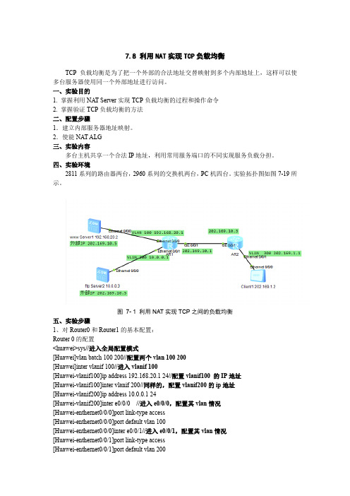
7.8 利用NAT实现TCP负载均衡TCP负载均衡是为了把一个外部的合法地址交替映射到多个内部地址上,这样可以使多台服务器使用同一个外部地址进行访问。
一、实验目的1. 掌握利用NAT Server实现TCP负载均衡的过程和操作命令2. 掌握验证TCP负载均衡的方法二、配置步骤1.建立内部服务器地址映射。
2.使能NAT ALG三、实验内容多台主机共享一个合法IP地址,利用常用服务端口的不同实现服务负载分担。
四、实验环境2811系列的路由器两台,2960系列的交换机两台,PC机四台。
实验拓扑图如图7-19所示。
图7- 1利用NAT实现TCP之间的负载均衡五、实验步骤1、对Router0和Router1的基本配置:Router 0的配置<huawei>sys//进入全局配置模式[Huawei]vlan batch 100 200//配置两个vlan 100 200[Huawei]inter vlanif 100//进入vlanif 100[Huawei-vlanif100]ip address 192.168.20.1 24//配置vlanif100 的IP地址[Huawei-vlanif100]inter vlanif 200//同样的,配置vlanif200的ip地址[Huawei-vlanif200]ip address 10.0.0.1 24[Huawei-vlanif200]inter e0/0/0//进入e0/0/0,配置其vlan情况[Huawei-enthernet0/0/0]port link-type access[Huawei-enthernet0/0/0]port default vlan 100[Huawei-enthernet0/0/0]inter e0/0/1//进入e0/0/1,配置其vlan情况[Huawei-enthernet0/0/1]port link-type access[Huawei-enthernet0/0/1]port default vlan 200[Huawei-enthernet0/0/1]q[Huawei]nat alg ftp enable //使能ftpalg,作用是改变ftp协议内传输的ip地址[Huawei]inter g0/0/1//进入g0/0/1 配置IP地址和natserver信息[Huawei-GigabitEthernet0/0/1]ip address 202.169.10.1 24[Huawei-GigabitEthernet0/0/1]nat server protocol tcp global 202.169.10.5 www inside192.168.20.2 www//配置www服务器的映射[Huawei-GigabitEthernet0/0/1]nat server protocol tcp global 202.169.10.5 ftp inside 10.0.0.3 ftp//配置ftp服务器的映射[Huawei-GigabitEthernet0/0/1]q[Huawei]ip route-static 0.0.0.0 0.0.0.0 202.169.10.3 //配置静态路由Router 1的配置<huawei>sys[Huawei]vlan batch 100[Huawei]inter vlanif 300[Huawei-vlanif100]ip address 202.169.1.1 24[Huawei-vlanif100]inter e0/0/1[Huawei-enthernet0/0/0]port link-type access[Huawei-enthernet0/0/0]port default vlan 300[Huawei-enthernet0/0/0]inter g0/0/1[Huawei-GigabitEthernet0/0/1]ip address 202.169.10.3 24[Huawei-GigabitEthernet0/0/1]q[Huawei]ip route-static 0.0.0.0 0.0.0.0 202.169.10.12、配置各服务器,主机的地址3、配置服务器信息(1)配置www服务器配置www服务器,在文件夹内放置一个文件名为default.htm的网页文件(2)配置ftp服务器4、测试打开Client1的客户端信息,分别在ftp和http客户端,进行测试。
如何设置路由器的双WAN口备份

如何设置路由器的双WAN口备份在当前的互联网时代,一个稳定快速的网络连接对于个人和企业来说都非常重要。
由于网络连接的不稳定性,经常会出现网络中断或速度慢的情况。
为了解决这一问题,许多路由器都配备了双WAN口备份的功能,可以实现两条宽带线路的备份,保证网络的连通性和稳定性。
本文将介绍如何设置路由器的双WAN口备份,以提高网络的可靠性。
第一步:确认路由器支持双WAN口备份功能首先,您需要确认您购买的路由器是否支持双WAN口备份功能。
您可以查看路由器的产品手册或者上网搜索相关信息。
如果您的路由器支持这一功能,那么您可以继续下一步的设置。
第二步:连接宽带线路在设置双WAN口备份之前,您需要先连接两条宽带线路到路由器的WAN口。
使用正确的网线将宽带的输出连接到路由器的WAN口1和WAN口2。
确保两条宽带线路都连接稳定,并且都已经正常工作。
第三步:登录路由器管理页面打开您的浏览器,输入路由器的默认IP地址,通常为192.168.1.1或192.168.0.1,按下回车键。
在弹出的登录页面中,输入您的管理员用户名和密码进行登录。
如果您不确定管理员用户名和密码是什么,您可以参考路由器的说明书或者联系路由器厂家获取相关信息。
第四步:进入双WAN设置页面登录成功后,您将看到路由器的管理页面。
根据路由器的型号和品牌的不同,双WAN设置页面可能会有所不同,但通常可以在“WAN设置”、“双WAN”或者“负载均衡”等选项中找到相关设置。
第五步:启用双WAN口备份功能在双WAN设置页面中,您可以看到“双WAN口备份”或者“备份模式”等选项。
选择启用双WAN口备份功能,并进行相应的设置。
通常,您可以选择设置主WAN口和备用WAN口的优先级或权重。
您可以根据您的需求和实际情况进行设置,以达到最佳的网络性能。
第六步:保存设置并重启路由器完成设置后,不要忘记点击“保存”或“应用”按钮,将设置保存到路由器中。
然后,您需要重启路由器使设置生效。
路由器实现网络负载均衡的三种模式

路由器实现网络负载均衡的三种模式“负载均衡”概念运用在网络上简单来说是利用多个网络设备通道均衡分担流量。
就像是寺庙一天要挑10桶水1个尚必需要走10趟但同时指派10个和尚却只要一趟即可完成工作的道理一样。
负载均衡可运用多个网络设备同时工作达成加速网络信息的处理能力进而优化网络设备的性能取代设备必须不停升级或淘汰的命运。
目前普遍被运用在网络设备中如服务器、路由器、交换机等。
目前提出的三种不同的负载均衡模式可较全面的包含各种网络架构中所应采取措施三种模式分别是模式一智能型负载均衡智能型负载均衡模式是依据接入WAN端带宽的大小比例自动完成负载均衡工作进一步协助达成带宽使用率的优化目的。
Qno侠诺在智能型负载均衡模式中提供了联机数均衡与IP均衡两种选择。
联机数均衡是依据WAN端带宽大小比例将内网所有的联网机数作均衡分配。
例如WAN1接入4M、WAN2接入2M则联机数就会依据2:1分配。
此种配置是网管员最一般的配置模式。
而IP均衡模式是为了避免某些网站EX银行网站或HTTPS类型的网站只能接受来自同一个公网IP的所发出封包的瓶颈。
如果采用联机数负载均衡模式会发生该IP所发出的访问封包不一定是从固定WAN口流出造成特定网站拒绝服务导致断线的情况发生。
如果采用IP均衡让IP依据WAN端带宽大小进行比例均衡分配例如WAN1与WAN2的带宽比例为2:1则PC1、PC2走WAN1PC3走WAN2PC4、PC5走WAN1……即可达到同一个内网PC所发出的应用服务封包都从固定的WAN口公网IP流出而整体内网IP也会依据带宽大小比例自动进行均衡配置。
此种配置比较适合常常需要进入特定网站时选择。
模式二指定路由指定路由比起智能型负载均衡而言是保留了更多的自由设定弹性与例外原则。
由于智能型负载均衡是针对整体内网联机数或是整体IP进行均衡分配。
并不能个别指定某种应用服务、某个特定IP、某个特定网址通过哪个WAN口出去。
所以有时会造成特定的服务例如邮件、VOIP 等或特定的人士公司老板、高管等不能有享有优先或例外的不便。
路由器-双出口做NAT实现负载分担配置

1、通过在路由上配置两条等值路由来实现负载分担
2、如果只想实现NAT的主备用,只需要修改两条默认路由为不同的优先级即可
#
interface NULL0
#
ip route-static 0.0.0.0 0.0.0.0 202.1.1.1 preference 60/配置默认路由/
ip route-static 0.0.0.0 0.0.0.0 61.1.1.1 preference 60/配置默认路由/
#
user-interface con 0
202.1.1.1 Serial0/0
61.1.1.0/30 DIRECT 0 0 61.1.1.6 Serial0/1
61.1.1.2/32 DIRECT 0 0 61.1.1.5 Serial0/1
61.1.1.1/32 DIRECT 0 0 127.0.0.1 InLoopBack0
127.0.0.0/8 DIRECT 0 0 127.0.0.1 InLoopBack0
rule 0 permit source 192.168.0.0 0.0.0.255
rule 1 deny
#
interface Ethernet0/0
ip address 192.168.0.1 255.255.255.0/内网网关/
nat outbound 2000
#
interface Serial0/0
6202.1.1.212288 192.168.0.2 1036 200.1.1.1 23
VPN: 0, status: 11, TTL: 24:00:00, Left: 23:59:55
661.1.1.212289 192.168.0.3 1035 200.1.1.1 23
H3C 负载分担、链路备份的实现过程详解
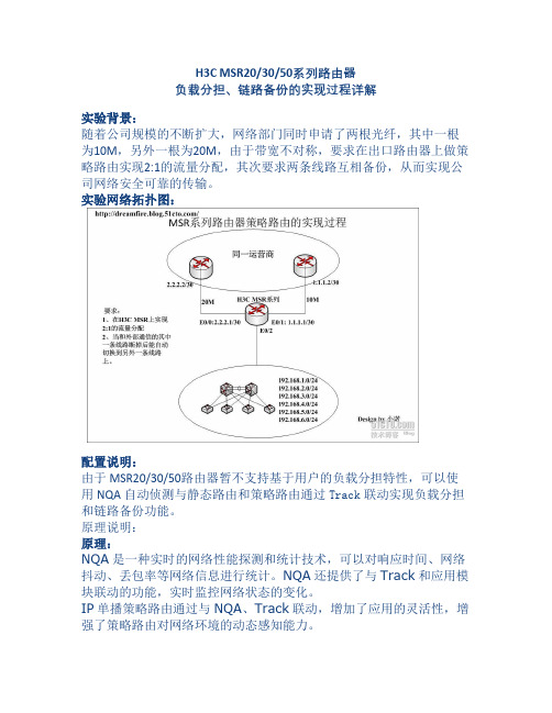
H3C MSR20/30/50系列路由器负载分担、链路备份的实现过程详解实验背景:随着公司规模的不断扩大,网络部门同时申请了两根光纤,其中一根为10M,另外一根为20M,由于带宽不对称,要求在出口路由器上做策略路由实现2:1的流量分配,其次要求两条线路互相备份,从而实现公司网络安全可靠的传输。
实验网络拓扑图:配置说明:由于MSR20/30/50路由器暂不支持基于用户的负载分担特性,可以使用NQA自动侦测与静态路由和策略路由通过Track联动实现负载分担和链路备份功能。
原理说明:原理:NQA是一种实时的网络性能探测和统计技术,可以对响应时间、网络抖动、丢包率等网络信息进行统计。
NQA还提供了与Track和应用模块联动的功能,实时监控网络状态的变化。
IP单播策略路由通过与NQA、Track联动,增加了应用的灵活性,增强了策略路由对网络环境的动态感知能力。
策略路由可以在配置报文的发送接口、缺省发送接口、下一跳、缺省下一跳时,通过Track与NQA关联。
如果NQA探测成功,则该策略有效,可以指导转发;如果探测失败,则该策略无效,转发时忽略该策略。
ICMP-echo功能是NQA最基本的功能,遵循RFC 2925来实现,其实现原理是通过发送ICMP报文来判断目的地的可达性、计算网络响应时间及丢包率。
ICMP-echo测试成功的前提条件是目的设备要能够正确响应ICMP echo request报文。
NQA客户端会根据设置的探测时间及频率向探测的目的IP地址发ICMP echorequest报文,目的地址收到ICMP echo request报文后,回复ICMP echo reply报文。
NQA客户端根据ICMP echo reply报文的接收情况,如接收时间和报文个数,计算出到目的IP地址的响应时间及丢包率,从而反映当前的网络性能及网络情况。
ICMP-echo测试的结果和历史记录将记录在测试组中,可以通过命令行来查看探测结果和历史记录。
H3C手册-路由负载分担与备份

路由负载分担与备份引入通过在路由表中生成具有多个不同下一跳的等值路由,路由可以在多路径上实现负载分担。
同时,合静动路协议中实现理的配置静态与动态路由协议,可以在网络中实现路由备份,提高路由可靠性。
本章介绍静态等值路由的配置,如何通过浮动静态路由对动态路由实现由的配置如何通过浮动静态路由对动态路由实现备份,如何对拨号网络中的动态路由实现备份。
课程目标学习完本课程,您应该能够:⏹掌握路由负载分担原理⏹掌握路由备份的原理和应用⏹掌握浮动静态路由的原理及应用掌握动路份⏹掌握动态路由备份的原理及应用目录⏹路由负载分担⏹路由备份ECMPG0/1G0/040.0.0.0/24G1/010.0.0.2/24目的地址/掩码下一跳地址出接口度量值20.0.0.1/32127.0.0.1InLoop0040.0.0.0/2420.0.0.2G0/12 30.0.0.2G1/02●通过ECMP(多路径等值路由),系统可实现路由负载分担●分担方式有基于流和基于包两种路由备份G0/140000/24G0/040.0.0.0/24G1/010.0.0.2/24目的地址/掩码优先级下一跳地址出接口40.0.0.0/246030.0.0.2G1/0G0/140.0.0.0/24G0/0G1/010.0.0.2/24下一跳地址目的地址/掩码优先级下跳地址出接口40.0.0.0/2410020.0.0.2G0/1目录⏹路由负载分担⏹路由备份[Router]ip route-static 40.0.0.0 255.255.255.0 S2/0 preference 120S2/0ISP40.0.0.0/24G0/0G1/010.0.0.2/24目的地址/掩码来源优先级下一跳地址出接口来优先接40.0.0.0/24RIP10030.0.0.2G1/0配置的备份静态路由优先级小于当前路由,称为浮动静态路由[Router]ospf 1[Router-ospf-1]preference 120G0/140.0.0.0/24G0/0G1/010.0.0.2/24目的地址/掩码来源优先级下一跳地址出接口来优先接40.0.0.0/24RIP10030.0.0.2G1/0配置的备份动态路由优先级小于当前路由,称为动态路由备份拨号链路上动态路由备份[Router] standby routing-rule 1 ip 40.0.0.1 24[Router-Bri3/0] standby routing-group 1Bri3/0ISDN40.0.0.0/24G0/0G1/010.0.0.2/24目的地址/掩码来源优先级下一跳地址出接口来优先接40.0.0.0/24OSPF6030.0.0.2G1/0拨号链路上,可使用standby routing 特性来实现动态路由备份本章总结⏹通过等值路由可实现负载分担⏹通过浮动静态路由可对动态路由实行备份⏹动态路由间可实现互相备份动路间可实现相备份⏹拨号链路上可使用standby routing 特性实现动态路由备份。
h3csecpath防火墙在双出口下通过策略路由实现负载分担的典型配置

H3C S e c P a t h防火墙在双出口下通过策略路由实现负载分担的典型配置-CAL-FENGHAI-(2020YEAR-YICAI)_JINGBIANSecPath安全产品在双出口下通过策略路由实现负载分担的典型配置一、组网需求:SecPath1000F防火墙部署在出口,有电信和网通两个出口,要求PC1通过电信的出口,PC2通过网通的出口,在任意一个出口出现故障的时候,需要能够自动切换到另外一个出口。
二、组网图radius scheme system#domain system#acl number 3000 //配置nat转换地址范围rule 0 permit ip source 192.168.1.0 0.0.0.255rule 1 permit ip source 172.16.1.0 0.0.0.255rule 2 deny ipacl number 3001 //配置策略路由的ACLrule 0 permit ip source 172.16.1.0 0.0.0.255rule 1 deny ip#interface Aux0async mode flow#interface GigabitEthernet0/0ip address 202.38.1.1 255.255.255.0nat outbound 3000#interface GigabitEthernet0/1ip address 61.1.1.1 255.255.255.0nat outbound 3000#interface GigabitEthernet1/0ip address 10.0.0.1 255.255.255.0ip policy route-policy test //应用策略路由#interface GigabitEthernet1/1#interface Encrypt2/0#interface NULL0#firewall zone localset priority 100#firewall zone trustadd interface GigabitEthernet1/0set priority 85#firewall zone untrustadd interface GigabitEthernet0/0add interface GigabitEthernet0/1set priority 5#firewall zone DMZset priority 50#firewall interzone local trust#firewall interzone local untrust#firewall interzone local DM#firewall interzone trust untrust#firewall interzone trust DMZ#firewall interzone DMZ untrust#route-policy test permit node 10 //配置策略路由if-match acl 3001apply ip-address next-hop 61.1.1.2#ip route-static 0.0.0.0 0.0.0.0 202.38.1.2 preference 60ip route-static 0.0.0.0 0.0.0.0 61.1.1.2 preference 70ip route-static 172.16.1.0 255.255.255.0 10.0.0.2 preference 60ip route-static 192.168.1.0 255.255.255.0 10.0.0.2 preference 60#四、配置关键点1. 在配置nat outbound的时候,必须允许所有的网段进行地址转换;2. 在内网口应用策略路由;3. 配置策略路由时,必须应用下一跳地址,不能应用接口地址。
互联网双出口解决方案
运营商的很多客户,特别是网吧老板,都是靠网络连接来营业的,网络连接可靠性对这些boss而言尤其重要,常见的单线路(链路)连接互联网就变得不那么给力,一旦线路故障,整个业务就歇菜了,他们选择往往是双运营商双线路,这种模式我们也称为互联网双出口。
双出口情况下有几种解决方案,应该如何在解决方案中选择是我们这期专栏要讨论的内容。
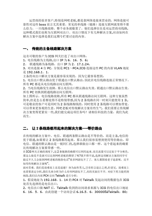
一、传统的主备线路解决方案这名可敬的客户为ICG网关打造了双出口网络:1. 电信线路为主线路,出口IP为6。
16。
5。
6;2。
联通线路为备线路,出口IP为2。
17.1.24;3. 对内连接4台PC,分别是PC1~PC4,ICG连接这些PC的内部VLAN地址是192.168.1。
1。
主备的双出口解决方案是最容易实现的,因为它最容易想到:1. 电信出口默认路由优于联通出口默认路由,因此在电信线路连接正常情况下,所有PC都是从电信线路访问互联网;2. 当电信线路发生故障,那么电信出口默认路由失效,联通出口默认路由生效,所有PC切换到联通线路访问互联网。
如上图所示,电信线路故障,所有PC都从联通线路访问互联网。
这种方案虽然简单,但是怎么看都觉得不是特别带感,因为2条线路在同一时刻只能使用1条,可是敬业的客户可是同时为2条线路掏钱的,同时使用2条线路可以增加带宽,可以带来更客观的生意,网吧老板对传统解决方案有些生气,我们需要让传统解决方案变得更紧实一些,我们能完成这项任务吗?请相信科技的力量,我们为此而生。
二、让2条线路都用起来的解决方案—-等价路由在传统的解决方案中,电信、联通两条默认路由是不等价的,而是主备,电信的优于联通,如果要让2条线路都用起来,那么我们很容易想到使用等价路由,即电信、联通的默认路由是一视同仁的,选择谁做出口都一样,这个看起来的确要比传统解决方案要带感一些。
在ICG网关正确的调度下,这2条链路的确都可以利用起来,而且流量可以近似于平分秋色,那这么做是不是就可以达到网吧老板的期望了呢?我不得不说,选择这项解决方案的同学可能过不久又会接到网吧老板的抱怨电话“很多网游玩不了了,客人都围着老子退款呢,还不如用传统解决方案呢".面对责难,我们是迎难而上还是退避?身为血性男儿,岂有轻言退让之理,但老兄,迎难而上也需要淡定分析,我们先来分析为什么有些网游玩不了,有的页面打不开,对症下药方能药到病除.我们以内部PC4访问Tektalk进行分析:1. 假设地址为192.168。
- 1、下载文档前请自行甄别文档内容的完整性,平台不提供额外的编辑、内容补充、找答案等附加服务。
- 2、"仅部分预览"的文档,不可在线预览部分如存在完整性等问题,可反馈申请退款(可完整预览的文档不适用该条件!)。
- 3、如文档侵犯您的权益,请联系客服反馈,我们会尽快为您处理(人工客服工作时间:9:00-18:30)。
思科路由器双WAN口负载分担并NAT及互为备份说明:客户接入ISP1及ISP2,部有4 个网段分别是:192.168.10.0/24192.168.20.0/2410.10.10.0/2420.20.20.20/24正常模式为192.168.10.0和10.10.10.0两个网段优先走ISP1,192.168.20.0和202.20.20.0两个网段优先走ISP2。
当IPS1线路中断时(即使R3接IPS1的接口是UP)192.168.10.0和10.10.10.0两个网段会自动转到ISP2,ISP2中断时同亦。
下面是拓扑图,及各台设备的配置文档,在GNS3上模拟测试成功。
(在网络上一直是伸手党,现在也分享下自己的经验,有不当之处还请指教,谢谢)分别在R1、R2均配置loopback 0 1.1.1.1/32为测试对象,R3为边界路由器,配置最多放在最后R1R1#sh runBuilding configuration...Current configuration : 761 bytes!version 12.4service timestamps debug datetime msecservice timestamps log datetime msecno password-encryption!hostname R1!boot-start-markerboot-end-marker!!no aaa new-model!!ip cefno ip domain lookup!!interface Loopback0ip address 1.1.1.1 255.255.255.255!interface FastEthernet0/0ip address 11.11.11.3 255.255.255.248 duplex autospeed auto!interface FastEthernet0/1no ip addressshutdownduplex autospeed auto!ip route 11.11.11.0 255.255.255.248 11.11.11.1 !no ip http serverno ip http secure-server!control-plane!gatekeepershutdown!!line con 0exec-timeout 0 0logging synchronousstopbits 1line aux 0stopbits 1line vty 0 4!endR2R2#sh runBuilding configuration...Current configuration : 761 bytes!version 12.4service timestamps debug datetime msec service timestamps log datetime msecno password-encryption!hostname R2!boot-start-markerboot-end-marker!!no aaa new-model!!ip cefno ip domain lookup!!interface Loopback0ip address 1.1.1.1 255.255.255.255!interface FastEthernet0/0ip address 22.22.22.3 255.255.255.248 duplex autospeed auto!interface FastEthernet0/1no ip addressshutdownduplex autospeed auto!ip route 22.22.22.0 255.255.255.248 22.22.22.1 !no ip http serverno ip http secure-servercontrol-plane!gatekeepershutdown!!line con 0exec-timeout 0 0logging synchronousstopbits 1line aux 0stopbits 1line vty 0 4!endR4R4#SH RUNBuilding configuration...Current configuration : 755 bytes!version 12.4service timestamps debug datetime msec service timestamps log datetime msec no password-encryption!hostname R4!boot-start-markerboot-end-marker!!no aaa new-model!!ip cefno ip domain lookup!!!!!!!!!!!!!!!!!!!!!!!interface Loopback0ip address 10.10.10.10 255.255.255.0 !interface FastEthernet0/0ip address 192.168.10.10 255.255.255.0 duplex autospeed auto!interface FastEthernet0/1no ip addressshutdownduplex autospeed auto!ip route 0.0.0.0 0.0.0.0 192.168.10.1!no ip http serverno ip http secure-server!!!!!!control-plane!!!!!!gatekeepershutdown!!line con 0exec-timeout 0 0logging synchronousstopbits 1line aux 0stopbits 1line vty 0 4!!endR5R5#SH RUNBuilding configuration...Current configuration : 757 bytes!version 12.4service timestamps debug datetime msec service timestamps log datetime msec no password-encryption!hostname R5!boot-start-markerboot-end-marker!!no aaa new-model!!ip cefno ip domain lookup!!!!!!!!!!!!!!!!!!!!!!!interface Loopback0ip address 20.20.20.20 255.255.255.0 !interface FastEthernet0/0ip address 192.168.20.20 255.255.255.0 duplex autospeed auto!interface FastEthernet0/1no ip addressshutdownduplex autospeed auto!ip route 0.0.0.0 0.0.0.0 192.168.20.254 !no ip http serverno ip http secure-server!!!!!control-plane!!!!!!gatekeepershutdown!!line con 0exec-timeout 0 0logging synchronousstopbits 1line aux 0stopbits 1line vty 0 4!!endR6R6#SH RUNBuilding configuration...Current configuration : 1548 bytes!version 12.4service timestamps debug datetime msec service timestamps log datetime msec no password-encryption!hostname R6!boot-start-markerboot-end-marker!no aaa new-model!resource policy!memory-size iomem 5ip cef!!!!no ip domain lookup!!!!!!!!!!!!!!!!!!!!!!!interface FastEthernet0/0 no ip address shutdownduplex autospeed auto!interface FastEthernet0/1 no ip address shutdownspeed auto!interface FastEthernet1/0switchport mode trunk!interface FastEthernet1/1!interface FastEthernet1/2!interface FastEthernet1/3!interface FastEthernet1/4switchport access vlan 10!interface FastEthernet1/5switchport access vlan 20!interface FastEthernet1/6!interface FastEthernet1/7!interface FastEthernet1/8!interface FastEthernet1/9!interface FastEthernet1/10!interface FastEthernet1/11!interface FastEthernet1/12!interface FastEthernet1/13!interface FastEthernet1/14!interface FastEthernet1/15!interface Vlan1no ip address!interface Vlan10ip address 192.168.10.254 255.255.255.0 !ip address 192.168.20.254 255.255.255.0!ip route 0.0.0.0 0.0.0.0 192.168.10.1ip route 10.10.10.0 255.255.255.0 192.168.10.10 ip route 20.20.20.0 255.255.255.0 192.168.20.20 !!no ip http serverno ip http secure-server!!!!!!!control-plane!!!!!!!!!!line con 0exec-timeout 0 0logging synchronousline aux 0line vty 0 4!!webvpn context Default_contextssl authenticate verify all!no inservice!!endR6#R3R3#SH RUNBuilding configuration...Current configuration : 2739 bytes!version 12.4service timestamps debug datetime msecservice timestamps log datetime msecno password-encryption!hostname R3!boot-start-markerboot-end-marker!!no aaa new-model!!ip cefno ip domain lookup!!ip sla monitor 1type echo protocol ipIcmpEcho 11.11.11.3 source-interface FastEthernet0/0 frequency 10ip sla monitor schedule 1 life forever start-time nowip sla monitor 2type echo protocol ipIcmpEcho 22.22.22.3 source-interface FastEthernet0/1 frequency 10ip sla monitor schedule 2 life forever start-time now!!!!!!!!!!!!!!!!track 1 rtr 1 reachability!track 2 rtr 2 reachability!!!!!interface FastEthernet0/0ip address 11.11.11.1 255.255.255.248 ip nat outsideip virtual-reassemblyduplex autospeed auto!interface FastEthernet0/1ip address 22.22.22.1 255.255.255.248 ip nat outsideip virtual-reassemblyduplex autospeed auto!interface FastEthernet1/0no ip addressshutdownduplex autospeed auto!interface FastEthernet1/1no ip addressshutdownduplex autospeed auto!interface FastEthernet2/0no ip addressduplex fullinterface FastEthernet2/0.10encapsulation dot1Q 10ip address 192.168.10.1 255.255.255.0ip nat insideip virtual-reassemblyip policy route-map test!ip route 0.0.0.0 0.0.0.0 11.11.11.3ip route 0.0.0.0 0.0.0.0 22.22.22.3ip route 10.10.10.0 255.255.255.0 192.168.10.254ip route 20.20.20.0 255.255.255.0 192.168.10.254ip route 192.168.20.0 255.255.255.0 192.168.10.254!no ip http serverno ip http secure-server!ip nat inside source route-map 1 interface FastEthernet0/0 overload ip nat inside source route-map 2 interface FastEthernet0/1 overload ip nat inside source route-map 3 interface FastEthernet0/1 overload ip nat inside source route-map 4 interface FastEthernet0/0 overload !access-list 10 permit 192.168.10.0 0.0.0.255access-list 10 permit 10.10.10.0 0.0.0.255access-list 20 permit 192.168.20.0 0.0.0.255access-list 20 permit 20.20.20.0 0.0.0.255!route-map test permit 10match ip address 10set ip next-hop verify-availability 11.11.11.3 1 track 1set ip next-hop verify-availability 22.22.22.3 2 track 2!route-map test permit 20match ip address 20set ip next-hop verify-availability 22.22.22.3 1 track 2set ip next-hop verify-availability 11.11.11.3 2 track 1!route-map 1 permit 10match ip address 10match interface FastEthernet0/0!route-map 2 permit 10match ip address 20match interface FastEthernet0/1route-map 3 permit 10 match ip address 10 !route-map 4 permit 10 match ip address 20 !!!!control-plane!!!!!!gatekeeper shutdown!!line con 0exec-timeout 0 0 logging synchronous stopbits 1line aux 0stopbits 1line vty 0 4!!endR3#。
