材料研究方法课后习题答案jd9-1
材料分析方法课后习题答案

材料分析方法课后习题答案材料分析方法课后习题答案材料分析方法是现代科学研究中非常重要的一门学科,它涉及到材料的组成、结构和性质等方面的研究。
在材料分析方法课程中,我们学习了各种分析方法的原理和应用。
下面,我将根据课后习题,对其中的几个问题进行解答,并对相关的知识进行深入的探讨。
1. 什么是材料分析方法?材料分析方法是指通过一系列的实验技术和仪器设备,对材料的组成、结构和性质进行研究和分析的一门学科。
它可以帮助科学家们了解材料的内部结构和性质,从而为材料的设计、制备和应用提供科学依据。
2. 材料分析方法的分类有哪些?材料分析方法可以根据所使用的原理和技术进行分类。
常见的分类包括:光学分析方法、电子显微镜分析方法、表面分析方法、热分析方法、光谱分析方法等。
每种分类又包含了许多具体的方法和技术。
3. 光学分析方法有哪些?光学分析方法是利用光学原理对材料进行分析的方法。
其中包括:光学显微镜、红外光谱、紫外可见光谱、拉曼光谱等。
这些方法可以用于观察材料的形貌、表面结构以及分子结构等。
4. 电子显微镜分析方法有哪些?电子显微镜分析方法是利用电子束与材料相互作用来对材料进行分析的方法。
常见的电子显微镜包括:扫描电子显微镜(SEM)和透射电子显微镜(TEM)。
它们可以提供高分辨率的图像,帮助研究人员观察材料的微观结构和成分。
5. 表面分析方法有哪些?表面分析方法是研究材料表面组成和性质的方法。
常见的表面分析方法包括:扫描电子显微镜(SEM)、原子力显微镜(AFM)、X射线光电子能谱(XPS)等。
这些方法可以提供关于材料表面的化学成分、形貌和结构等信息。
6. 热分析方法有哪些?热分析方法是通过对材料在不同温度下的热性质变化进行研究的方法。
常见的热分析方法包括:差热分析(DSC)、热重分析(TGA)、热膨胀分析(TMA)等。
这些方法可以用于研究材料的热稳定性、热分解行为等。
7. 光谱分析方法有哪些?光谱分析方法是利用物质与辐射相互作用产生的光谱信息来研究材料的方法。
材料现代研究方法习题加答案-考试实用

第二部分电子显微分析一、电子光学1、电子波特征,与可见光有何异同?2、电磁透镜的像差(球差;色差;像散;如何产生,如何消除和减少)球差即球面像差,是磁透镜中心区和边沿区对电子的折射能力不同引起的,其中离开透镜主轴较远的电子比主轴附近的电子折射程度过大。
用小孔径成像时可使球差明显减小。
像散是由于电磁透镜的轴向磁场非旋转对称引起。
透镜磁场不对称,可能是由于极靴被污染,或极靴的机械不对称性,或极靴材料各项磁导率差异引起。
象散可由附加磁场的电磁消象散器来校正。
色差是由入射电子的波长或能量的非单一性造成的。
稳定加速电压和透镜电流可减小色差。
3、电磁透镜的分辨率、景深和焦长(与可见光),影响因素电磁透镜的分辨率主要由衍射效应和像差来决定。
(1)已知衍射效应对分辨率的影响(2)像差对分辨的影响。
像差决定的分辨率主要是由球差决定的。
景深:当像平面固定时(像距不变),能维持物像清晰的范围内,允许物平面(样品)沿透镜主轴移动的最大距离。
焦长:固定样品的条件下(物距不变),象平面沿透镜主轴移动时仍能保持物像清晰的距离范围,用D L表示。
二、透射电子显微镜1、透射及扫描电镜成像系统组成及成像过程(关系)扫描电镜成像原理:在扫描电镜中,电子枪发射出来的电子束,一般经过三个电磁透镜聚焦后,形成直径为0.02~20μm的电子束。
末级透镜(也称物镜,但它不起放大作用,仍是一个会聚透镜)上部的扫描线圈能使电子束在试样表面上作光栅状扫描。
通常所用的扫描电镜图象有二次电子象和背散射电子象。
2、光阑(位置、作用)光栏控制透镜成像的分辨率、焦深和景深以及图像的衬度、电子能量损失谱的采集角度、电子衍射图的角分辨率等等。
防止照明系统中其它的辐照以保护样品等3、电子衍射与x衍射有何异同电子衍射与X射线衍射相比的优点:1.电子衍射能在同一试样上将形貌观察与结构分析结合起来。
2.电子波长短,单晶的电子衍射花样婉如晶体的倒易点阵的一个二维截面在底片上放大投影,从底片上的电子衍射花样可以直观地辨认出一些晶体的结构和有关取向关系,使晶体结构的研究比X射线简单。
材料研究方法课后习题答案jd8-3
§8-3 试简要阐述判断出分子离子峰方法。
在判断分子离子峰时可参考以下几个方面的规律和经验方法:(1)分子离子稳定性的一般规律分子离子的稳定性与分子结构有关。
碳数较多、碳链较长(也有例外)和有支链的分子,分裂几率较高,其分子离子的稳定性低;而具有π键的芳香族化合物和共轭烯烃分子,分子离子稳定,分子离子峰大。
(2)分子离子峰质量数的规律(氮规则)由C、H、O组成的有机化合物,分子离子峰的质量一定是偶数。
由C、H、O、N组成的化合物,含奇数个N,分子离子峰的质量是奇数,含偶数个N,分子离子峰的质量则是偶数。
凡不符合氮规则者,就不是分子离子峰。
(3)分子离子峰与邻近峰的质量差是否合理如有不合理的碎片峰,就不是分子离子峰。
例如分子离子不可能裂解出两个以上的氢原子和小于一个甲基的基团,故分子离子峰的左面,不可能出现比分子离子的质量小3-14个质量单位的峰;若出现质量差15或18,这是由于裂解出-CH3或一分子水,因此这些质量差都是合理的。
(4)在判断分子离子峰时,还应注意形成 M+1 或 M-1 峰的可能性。
(5)降低电子轰击源的能量,观察质谱峰的变化:在不能确定分子离子峰时,可以逐渐降低电子流的能量;使分子离子的裂解减少。
这时所有碎片离子峰的强度都会减小,但分子高子峰的相对强度会增加。
仔细观察质荷比最大的峰是否在所有的峰中最后消失。
最后消失的峰即为分子离子峰。
有机化合物的质谱分析,最常应用电子轰击源作离子源,但在应用这种离子源时,有的化合物仅出现很弱的,有时甚至不出现分子离子分子峰,这样就使质谱失去一个很重要的作用。
为了得到分子离子峰,可以改用其它一些离子源,如场致电离源、化学电离源等。
材料研究方法(唐正霞)习题及答案

材料研究方法习题答案光学显微分析1.如何提高光学显微分析的分辨能力?①选择更短的波长,如紫外光、X射线、电子束等;②采用折射率很高的材料,如采用浸油显微镜;③增大显微镜的孔径角,如采用复合透镜以加大显微镜物镜的孔径角。
2.阐述光学显微镜分析用光片制备方法。
(1)取样:光片的取样部分应具有代表性,包含研究对象并满足特定要求;(2)镶嵌:对一些形状特殊尺寸细小而不易握持的样品需进行镶嵌;(3)磨光:去除样品表面损伤,获得光滑样品表面;(4)抛光:去除细磨痕以获得无暇镜面,并去除变形层;(5)浸蚀:使不同组织,不同相位晶粒以及晶粒内部与晶界处各受到不同程度浸蚀,形成差别,从而清晰的显示出材料的内部组织。
3.电磁波谱的主要参数波普区波长范围波数/cm-1频率/MHZ光子能量/ev 域Y射线0.5~140pm2×1010~7×1076×1014~2×10¹² 2.5×10⁶~8.3×10³ X射线10-3~10nm106~10103×1010~3×10¹⁴ 1.2×10⁶~1.24×10²紫外光10~400nm106~2.5×1043×1010~7.5×108124~3.1可见光400~750nm 2.5×10⁴~1.3×1047.5×108~4×10⁸ 3.1~1.65近外光730~3.1×10⁶nm 1.4×10⁴~3.2 4.1×10⁸~9.7×10⁴ 1.7~4×10⁻⁴微波 3.1×10⁶~3.1×10⁹nm0.0032~3.2 97~9.7×1044×10-4~4×10⁻⁷射频1~1000m10-5~0.010.3~300 1.2×10⁻⁹~1.24×10⁻⁶(1)σ=1/λ=1/(0.5×10-10)=2×1010cm-1 σ=1/λ=1/(140×10-10)=7×107cm-1 (2)σ=1/λ=1/(10-3×10-7)=1×1010cm-1 σ=1/λ=1/(10×10-7)=1×106cm-1v=c/λ=(3×108) /(10-3×10-9)×106=3×1014 MHZ、v=c/λ=(3×108) /(10×10-9)×106=3×1010MHZE=1240/λ=1240/10-3=1.2×106ev E=1240/λ=1240/10=1.24×102ev(3)λ=c/v =(3×10⁸) /(3×1010×106)=10-8m=10nmλ=c/v =(3×10⁸) /(7.5×108×106)=4×10-6m=400nmσ=1/λ=1/(10-6)=106cm-1 σ=1/λ=1/(400×10-5)=2.5×104cm-1E=1240/λ=1240/10=124ev E=1240/λ=1240/400=3.1ev (4)σ=1/λ=1/(400×10-7)=2.5×104cm-1 σ=1/λ=1/(750×10-7)=1.3×104cm-1 v=c/λ=(3×108) /(400×10-9)=7.5×1014HZ =7.5×10⁸MHZv=c/λ=(3×108) /(750×10-9)=4×1014HZ=4×108MHZE=1240/λ=1240/400=3.1ev E=1240/λ=1240/750=1.65ev(5)v=c/λ=(3×108) /(730×10-9)=4.1×1014HZ =4.1×10⁸MHZv=c/λ=(3×108) /(3.1×106×10-9)=9.7×1010HZ =9.7×10⁴MHZλ=hc/ E =1240/E=1240/1.7=730nm λ=hc/ E =1240/E=1240/4×10-4=3.1×106nmσ=1/λ=1/(730×10-7)=1.4×104cm-1 σ=1/λ=1/(3.1×106×10-7)=3.2cm-1(6)λ=hc/ E =1240/E=1240/4×10-4 =3.1×10⁶nmλ=hc/ E =1240/E=1240/4×10-7 =3.1×10⁹nmσ=1/λ=1/(3.1×106×10-7)=3.2cm-1 σ=1/λ=1/(3.1×109×10-7)=0.0032cm-1 v=c/λ=(3×108) /(3.1×106×10-9)=9.7×1010HZ =9.7×10⁴MHZv=c/λ=(3×108) /(3.1×109×10-9)=9.7×107HZ =97MHZ(7)σ=1/λ=1/100=0.01cm-1 σ=1/λ=1/1000×102=10-5cm-1v=c/λ=(3×108) /1 =3×10⁸HZ =300MHZv=c/λ=(3×108) /1000=3×105HZ =0.3MHZE=1240/λ=1240/10-6=1.24×10-6ev E=1240/λ=1240/(1000×10-6)=1.24×10-9evX射线衍射分析1.试述X射线的定义、性质,连续X射线和特征X射线的产生、特点。
材料研究方法课后题答案.docx
第]章1、 材'料是如何分类的?材料的结构层次有哪些?答:材料按化学组成和结构分为:金属材料、无机非金属材料、高分子材料、复合材料:按性能特征分为:结构材料、功能材料;按川途分为:建筑材料、航空材料、电子材料、半导体材料、生物材料、医川材料。
材料的结构层次有:微观结构、亚微观结构、显微结构、宏观结构。
2、 材料研究的主要任务和对象是什么,有哪些相应的研究方法?答:任务:材料研究应着垂于探索制备过程前后和使川过程中的物质变化规律,也就是在此基础上探明材料的 组成(结构)、合成(工艺过程)、性能和效能及其Z 间的相互关系,或者说找出经一定工艺流程获得的材料的组 成(结构)对于材料性能与川途的影响规律,以达到对材料优化设计的口的,从而将经验性工艺逐步纳入材料科 学与工程的轨道.研究对象和相应方法见书第三页表格。
3、 材料研究方法是如何分类的?如何理解现代研究方法的重要性?答:按研究仪器测试的信息形式分为图像分析法和非图像分析法;按工作原理,前者为显微术,后者为衍 射法和成分谱分析。
第2章1、简述现代材料研究的主X 射线实验方法在材料研究屮有那些主要应川? 答:现代材料研究的主X 射线实验方法在材料研究中主要佇以下儿种应丿山(1) X 射线物相定性分析:用于确定物质中的物相组成(2) X 射线物相定量分析:用于测定某物相在物质中的含量(3) X 射线晶体结构分析:用于推断测定晶体的结构 2、试推导Bragg 方程,并对方程中的主要参数的范围确定进行讨论. 答:见书第97页。
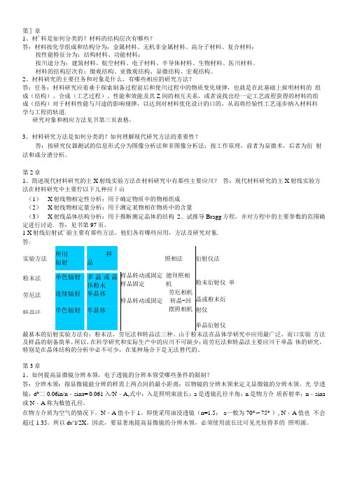
1 X 射线衍射试'验主要有那些方法,他们各有哪些应用,方法及研究对象.答:方法及样晶的制备简单,所以,在科学研究和实际生产中的应川不可缺少;而劳厄法和转晶法主要应川于单晶 体的研究,特别是在晶体结构的分析中必不可少,在某种场合下是无法替代的。
第3章1、如何提高显微镜分辨本领,电子透镜的分辨本领受哪些条件的限制?答:分辨木领:指显微镜能分辨的样需上两点间的最小距离;以物镜的分辨木领来定义显微镜的分辨木领。
高分子材料研究方法作业及答案样本

子平面摇摆。
卷曲振动: 分子基团围绕与基团相连分子的价键扭动。
5. 详述分子振动的类型.答6. 多原子分子振动的形式如何计算? 并举例说明。
答: ( 1) 对于非线性分子, 其分子振动的形式计算式为: 3n-6, 其中n为分子中所含原子数; ( 2) 对于线性分子, 其分子振动的形式计算式为: 3n-5。
例如: 非线性分子水分子的分子振动形式有3个, 分别为: 2个O-H 的伸缩振动和1个HOH的键角弯曲振动; 线性分子二氧化碳分子的分子振动形式有4个, 分别为: 对称伸缩振动、反对称伸缩振动、面内弯曲振动和面外弯曲振动。
7. 什么叫偶极矩?答;两个等量而异号的电荷所组成的系统,一个电荷的电量和两电荷间距离的乘积称电偶极子的偶极距.它是矢量,方向沿两电荷的连线,8. 分子振动吸收的条件?答: ( 1) 振动的频率与红外光光谱段的某频率相等, 吸收了红外光谱中这一波长的光, 能够把分子的能级从基态跃迁到激发态, 这是产生红外吸收光谱的必要条件。
( 2) 偶极矩的变化: 已知分子在振动过程中, 原子间的距离( 键长) 或夹角( 键角) 会发生变化, 这时可能引起分子偶极矩的变化, 结果产生了一个稳定的交变电场, 这个稳定的交变电场将和运动的具有相同频率的电磁辐射电场相互作用, 从而吸收辐射能量, 产生红外光谱的吸收。
9. 什么叫基频带、倍频带?答: 基频带: 分子吸收光子后, 从一个能级跃迁到相邻高一级能级产生的吸收。
倍频带: 分子吸收比原有能量大一倍的光子后, 跃迁两个以上能级产生的吸收峰。
10. 影响吸收带位置的因素?答: 影响吸收带位置的因素很多, 有外在的、人为的因素, 也有内在的、本质的因素。
( 1) 外在因素: 制备样品的方法、样品所处的物态、结晶条件、仪器系统的调节等, 均能影响吸收带的位置、强度及形状。
( 2) 内在因素: l) 质量效应: 对于同族元素, 由于彼此质量差别较大, 随着原子的质量增大, 它与同一元素形成的化学键的吸收带波数明显地减小。
材料分析测试技术_部分课后答案

9-1、电子波有何特征?与可见光有何异同?答:电子波特征:电子波属于物质波。
电子波的波长取决于电子运动的速度和质量,=h mvλ若电子速度较低,则它的质量和静止质量相似;若电子速度具有极高,则必须经过相对论校正。
·电子波和光波异同:不同:不能通过玻璃透镜会聚成像。
但是轴对称的非均匀电场和磁场则可以让电子束折射,从而产生电子束的会聚与发散,达到成像的目的。
电子波的波长较短,其波长取决于电子运动的速度和质量,电子波的波长要比可见光小5个数量级。
另外,可见光为电磁波。
相同:电子波与可见光都具有波粒二象性。
9-2、分析电磁透镜对电子波的聚焦原理,说明电磁透镜的结构对聚焦能力的影响。
聚焦原理:电子在磁场中运动,当电子运动方向与磁感应强度方向不平行时,将产生一个与运动方向垂直的力(洛仑兹力)使电子运动方向发生偏转。
在一个电磁线圈中,当电子沿线圈轴线运动时,电子运动方向与磁感应强度方向一致,电子不受力,以直线运动通过线圈;当电子运动偏离轴线时,电子受磁场力的作用,运动方向发生偏转,最后会聚在轴线上的一点。
电子运动的轨迹是一个圆锥螺旋曲线。
右图短线圈磁场中的电子运动显示了电磁透镜聚焦成像的基本原理:结构的影响:1)增加极靴后的磁线圈内的磁场强度可以有效地集中在狭缝周围几毫米的范围内;2)电磁透镜中为了增强磁感应强度,通常将线圈置于一个由软磁材料(纯铁或低碳钢)制成的具有内环形间隙的壳子里,此时线圈的磁力线都集中在壳内,磁感应强度得以加强。
狭缝的间隙越小,磁场强度越强,对电子的折射能力越大。
3)改变激磁电流可以方便地改变电磁透镜的焦距9--3、电磁透镜的像差是怎样产生的,如何消除和减少像差?像差有几何像差(球差、像散等)和色差球差是由于电磁透镜的中心区域和边沿区域对电子的会聚能力不同而造成的;为了减少由于球差的存在而引起的散焦斑,可以通过减小球差系数和缩小成像时的孔径半角来实现像散是由透镜磁场的非旋转对称而引起的;透镜磁场不对称,可能是由于极靴内孔不圆、上下极靴的轴线错位、制作极靴的材料材质不均匀以及极靴孔周围局部污染等原因导致的。
材料研究与测试方法复习题答案版

材料研究与测试方法复习题答案版材料研究与测试方法复习题答案版复习题一、名词解释1、系统消光: 把由于F HKL=0而使衍射线有规律消失的现象称为系统消光。
2、X射线衍射方向: 是两种相干波的光程差是波长整数倍的方向。
3、Moseley定律:对于一定线性系的某条谱线而言其波长与原子序数平方近似成反比关系。
4、相对强度:同一衍射图中各个衍射线的绝对强度的比值。
5、积分强度:扣除背影强度后衍射峰下的累积强度。
6、明场像暗场像:用物镜光栏挡去衍射束,让透射束成像,有衍射的为暗像,无衍射的为明像,这样形成的为明场像;用物镜光栏挡去透射束和及其余衍射束,让一束强衍射束成像,则无衍射的为暗像,有衍射的为明像,这样形成的为暗场像。
7、透射电镜点分辨率、线分辨率:点分辨率表示电镜所能分辨的两个点之间的最小距离;线分辨率表示电镜所能分辨的两条线之间的最小距离。
8、厚度衬度:由于试样各部分的密度(或原子序数)和厚度不同形成的透射强度的差异;9、衍射衬度:由于晶体薄膜内各部分满足衍射条件的程度不同形成的衍射强度的差异;10相位衬度:入射电子收到试样原子散射,得到透射波和散射波,两者振幅接近,强度差很小,两者之间引入相位差,使得透射波和合成波振幅产生较大差异,从而产生衬度。
11像差:从物面上一点散射出的电子束,不一定全部聚焦在一点,或者物面上的各点并不按比例成像于同一平面,结果图像模糊不清,或者原物的几何形状不完全相似,这种现象称为像差球差:由于电磁透镜磁场的近轴区和远轴区对电子束的汇聚能力不同造成的像散:由于透镜磁场不是理想的旋转对称磁场而引起的像差色差:由于成像电子的波长(或能量)不同而引起的一种像差12、透镜景深:在不影响透镜成像分辨本领的前提下,物平面可沿透镜轴移动的距离13、透镜焦深:在不影响透镜成像分辨本领的前提下,像平面可沿透镜轴移动的距离14、电子衍射:电子衍射是指当一定能量的电子束落到晶体上时,被晶体中原子散射,各散射电子波之间产生互相干涉现象。
材料研究方法作业答案

材料研究方法第二章思考题与习题一、判断题√1.紫外—可见吸收光谱是由于分子中价电子跃迁产生的。
×2.紫外—可见吸收光谱适合于所有有机化合物的分析。
×3.摩尔吸收系数的值随着入射波光长的增加而减少。
×4.分光光度法中所用的参比溶液总是采用不含待测物质和显色剂的空白溶液。
×5.人眼能感觉到的光称为可见光,其波长范围是200~400nm。
×6.分光光度法的测量误差随透射率变化而存在极大值。
√7.引起偏离朗伯—比尔定律的因素主要有化学因素和物理因素,当测量样品的浓度极大时,偏离朗伯—比尔定律的现象较明显。
√8.分光光度法既可用于单组分,也可用于多组分同时测定。
×9.符合朗伯—比尔定律的有色溶液稀释时,其最大吸收波长的波长位置向长波方向移动。
×10.有色物质的最大吸收波长仅与溶液本身的性质有关。
×11.在分光光度法中,根据在测定条件下吸光度与浓度成正比的比耳定律的结论,被测定溶液浓度越大,吸光度也越大,测定的结果也越准确。
()√12.有机化合物在紫外—可见区的吸收特性,取决于分子可能发生的电子跃迁类型,以及分子结构对这种跃迁的影响。
()×13.不同波长的电磁波,具有不同的能量,其大小顺序为:微波>红外光>可见光>紫外光>X射线。
()×14.在紫外光谱中,生色团指的是有颜色并在近紫外和可见区域有特征吸收的基团。
()×15.区分一化合物究竟是醛还是酮的最好方法是紫外光谱分析。
()×16.有色化合物溶液的摩尔吸光系数随其浓度的变化而改变。
()×17.由共轭体系π→π*跃迁产生的吸收带称为K吸收带。
()√18.红外光谱不仅包括振动能级的跃迁,也包括转动能级的跃迁,故又称为振转光谱。
()√19.由于振动能级受分子中其他振动的影响,因此红外光谱中出现振动偶合谱带。
()×20.确定某一化合物骨架结构的合理方法是红外光谱分析法。
材料研究方法作业题目及答案(全)-polymer-xiaoyi
材料研究方法作业题目及答案(全)此版本为老师布置的所有题目及答案。
答案内容参考了PPT、书以及其他版本的答案,并对某些部分做出了较大改动。
仅作复习参考!刘学良老师部分第3章X射线衍射分析1、X射线的波长范围大致为多少?X射线产生的基本原理及X射线管的基本结构。
1】X射线的波长范围:X射线是一种波长为10-2~102Å的电磁波,介于紫外线和γ射线之间。
2】X射线产生的基本原理:凡是高速运动的电子流或其他高能辐射流(γ射线、X射线、中子流等)被突然减速时均能产生X射线。
3】X射线管的基本结构:X射线管的本质是一个真空二极管,基本结构包括:①一个热阴极——绕成螺线形钨丝②一个阳极——铜质底座上镶以阳极靶材料,如W、Ag、Mo、Cu、Ni、Co、Fe、Cr等,产生不同特征的X射线③窗口——用对X射线吸收极少的材料,如Be、Al、轻质玻璃等制成。
④管内高真空10-7Toor2、X射线谱的基本类型及其特点。
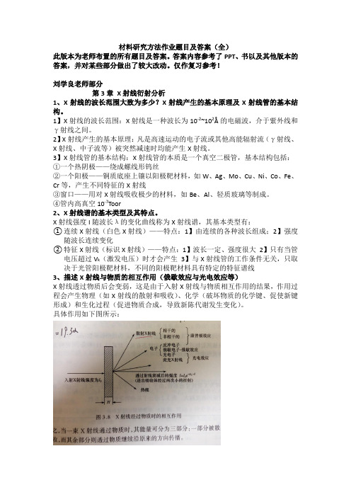
X射线强度I随波长λ的变化曲线称为X射线谱,其基本类型有:①连续X射线(白色X射线)——特点:1】由连续的各种波长组成;2】强度随波长连续变化②特征X射线(标识X射线)——特点:1】波长一定、强度很大2】只有当管电压超过V k(激发电压)时才会产生3】与X射线管的工作条件无关,只取决于光管阳极靶材料,不同的阳极靶材料具有特定的特征谱线3、描述X射线与物质的相互作用(俄歇效应与光电效应等)X射线透过物质后会变弱,这是由于入射X射线与物质相互作用的结果,作用过程会产生物理(如X射线的散射和吸收)、化学(破坏物质的化学键、促使新键形成)和生化过程(促进物质合成,导致新陈代谢发生变化)。
具体作用如下图所示:由图可见,当一束X射线通过物质时,其能量可分为三个部分:一部分被散射,一部分被吸收,其余部分则透过物质按方向继续传播。
其中:康普顿效应——散射光中除了有原波长λ0的X光外,还产生了波长λ>λ0的X光,其波长的增量随散射角的不同而变化俄歇效应——当较外层的电子跃迁到空穴时,所释放的能量随即在原子内部被吸收而逐出较外层的另一个次级光电子,此称为俄歇效应,所逐出的次级光电子称为俄歇电子。
北京航空航天大学911材料综合材料现代研究方法作业习题精选全文

可编辑修改精选全文完整版作业习题一、主要参考书1.王富耻. 材料现代分析测试方法[M],北京理工大学出版社,2006.2.高家武等. 高分子材料近代测试技术[M],北京航空航天大学出版社,1998.二、学习指导阅读作业:参考书1:材料现代分析测试方法第七章(266-288页)第六章(248-259页)第九章(334-337页)参考书2:高分子材料近代测试技术第三章(85-125页)总体学习目标:1.定性理解差热分析(DTA)、差示扫描量热法(DSC)、热重法(TG)和动态力学热分析(DMTA)等热分析技术的基本原理及影响因素;2. 掌握热分析曲线解析方法和热分析技术在材料研究领域中的具体应用;3.定性地理解在红外光谱(IR)中分子结构对吸收峰位置的影响;4.学会利用解析红外光谱图谱并辨别未知物分子结构中的官能团;5.定性地理解核磁共振(NMR)的物理原理及影响化学位移和自旋-自旋裂分的因素;6.学会解析核磁共振氢谱(1H-NMR),并学习综合利用IR和NMR等分析推断有机分子和聚合物的结构。
三、思考题节选X射线衍射解释名词:1.特征X射线 2.相干散射 3.倒易矢量 4.倒易球 5.光电效应 6.吸收限 7.俄歇效应 8.X射线的激发电压 9.X射线的工作电压 10.非相干散射11.晶带 12.晶带定律 13.倒易点阵简答题1.X射线产生的条件是什么?2.空间点阵与晶体结构是什么关系?3.干涉指数与晶面指数是什么关系?4.X射线在晶体中产生衍射的极限条件是什么?5.倒易矢量的基本性质?6.X射线分析中工作电压如何选择?7.X射线衍射仪中测角仪其什么作用?8.写出X射线定性物相分析的程序?9.X射线衍射仪有什么用途?10.什么是厄瓦尔德作图法?11.正点阵中,同一晶带的面在倒易空间中与什么相对应?12.四种类型点阵的系统消光规律?13.用厄瓦尔德图法解释劳厄法的成像原理和劳厄斑点的分布规律?14.什么是X射线粉末法衍射花样指数化方法?15.什么是X射线谱中,波长最短的短波限对应的X射线光子能量应是最大,但为什么最大强度出现在中央、16.说明标识X射线谱产生的机理。
材料研究方法思考题习题

材料研究方法思考题习题思考问题、练习和参考资料第1章1。
材料是如何分类的?材料的结构层次是什么?2。
材料研究的主要任务和对象是什么,相应的研究方法是什么?3.材料研究方法是如何分类的?如何理解现代研究方法的重要性?第2章1。
辨别晶体的颜色、多色性和吸收率。
为什么非各向同性体矿物晶体是多色的?2.什么是贝克线?它的运动规律是什么?效果如何?3。
什么是晶体的粗糙表面、突起和闪光突起?决定晶体粗糙度和突起等级的因素是什么?什么是干涉色?影响晶体干涉色的因素有哪些?5。
白云母有三个主要折射率Ng=1.588,Nm=1.582,Np=1.552。
如果要制造干涉色为1/4λ(147nm)的测试板,垂直于Ng截面的切片厚度应该是多少?6。
平行金红石(四方)(100)晶面呈薄片状,折射率计测得的C轴方向为2.616,垂直于C轴的方向为2.832;试着画出它的光学指标,并写出最大双折射及其正负光学性质7.取平行莫来石(斜方)斜方柱(110)的所有平面测得晶体的最大折射率为1.654,取垂直直斜方柱的所有平面(001)测得的折射率变化在1.644-1.642之间给定光轴平面//(010),试着画出它的光学指标,写出最大双折射,光学符号和光学方向8.辉石是正射晶体。
在正交偏振下,其最高干涉色是次黄(r = 880微米),⊥Bxa截面具有原色亮灰色干涉色(r = 210微米),设置Ng-Nm=0.019,并计算片材厚度9.将橄榄石晶体片的厚度设置为0.03毫米,Ng=1.689,Nm=1.670,Np=1.654,并询问:垂直Bxa切割平面、垂直Bxo平面和平行光轴平面之间的光程差是多少?10.如何使用锥光镜来识别晶体的光学和轴向特性?11.如何提高光学显微分析的分辨率?12.阐述了光学显微分析用光学片的制备方法。
13。
近场光学显微镜的原理及其与传统光学显微镜的异同分析14。
近场光学显微镜为什么能突破光学显微镜的分辨率极限?参考文献1。
材料科学基础课后习题答案9
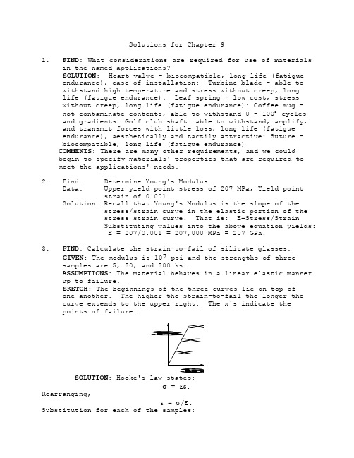
Solutions for Chapter 91. FIND: What considerations are required for use of materialsin the named applications?SOLUTION: Heart valve - biocompatible, long life (fatigueendurance), ease of installation: Turbine blade - able towithstand high temperature and stress without creep, longlife (fatigue endurance): Leaf spring - low cost, stresswithout creep, long life (fatigue endurance): Coffee mug -not contaminate contents, able to withstand 0 - 100︒ cyclesand gradients: Golf club shaft: able to withstand, amplify,and transmit forces with little loss, long life (fatigueendurance), aesthetically and tactily attractive: Suture -biocompatible, long life (fatigue endurance)COMMENTS: There are many other requirements, and we couldbegin to specify materials' properties that are required tomeet the applications' needs.2. Find: Determine Young's Modulus.Data: Upper yield point stress of 207 MPa, Yield pointstrain of 0.001.Solution: Recall that Young's Modulus is the slope of thestress/strain curve in the elastic portion of thestress strain curve. That is: E=Stress/StrainSubstituting values into the above equation yields:E = 207/0.001 = 207,000 MPa = 207 GPa.3. FIND: Calculate the strain-to-fail of silicate glasses.GIVEN: The modulus is 107 psi and the strengths of threesamples are 5, 50, and 500 ksi.ASSUMPTIONS: The material behaves in a linear elastic manner up to failure.SKETCH: The beginnings of the three curves lie on top ofone another. The higher the strain-to-fail the longer thecurve extends to the upper right. The x's indicate thepoints of failure.tiSanrtSOLUTION: Hooke's law states:σ = Eε.Rearranging,ε = σ/E.Substitution for each of the samples:ε = 5000 psi / 107 psi = 0.05%ε = 50,000 psi / 107 psi = 0.5%ε = 500,000 psi / 107 psi = 5%.COMMENTS: The smallest value represents that of ordinary window glass. The largest value is characteristic of an optical fiber.4. Find: Determine if the stress is above or below theyield stress. If the stress is below the yield stresscompute Young's Modulus.Data: The yield stress for the mild steel is 207 MPa. A specimen has a diameter of 0.01m and a length of0.1m. It is loaded in tension to 1000N anddeflects 6.077 x 10⁻⁶m.Solution: To solve this problem, we must first determine the applied tensile stress. Recall that the tensilestress is given by the formula: Stress=Force(P)/Area Normal to force (A). The cross sectionalarea is: A= πD2/4 = 3.1416x(0.01)2/4 = 7.85x10⁻⁵The stress is: Stress = 1000/7.85x10-5 = 12.7MPaThe applied stress is much less than the yieldstress. To obtain the Modulus recall thedefinition: E=σ/ε. We must thus compute thestrain in order to determine the Modulus:ε=∆l/l o = 6.077x10⁻⁶/0.1 = 6.077x10⁻⁵Thus E=12.7/6.077x10-5 = 2.09x10⁵ MPa.5. Find: Compute deflection of specimens.Data: E Al=70,460MPa, E Cu=122,500MPa, E W=388,080MPa,A=0.01m x 0.01m=10-4m2, Length(l o)=1m,Load(P)=5000N.Solution: Start with the relationship between stress andstrain for linear elastic behavior: σ=Eε (1)Note that: σ=P/A (2)ε=∆l/l o (3)Substitute (2) & (3) into (1): Thus P/A=E∆l/l o (4)Rearranging to solve for ∆l we have:∆l=Pl o/AE=5000 x 1/(10-4E)=5x107/E (5)Note that for ∆l to be in meters we require E tobe expressed in Pa. Using (5) and E in Pa we getthe following deflection values:Al=7.09x10⁻⁴m, Cu=4.08x10⁻⁴m, W=1.29x10⁻⁴m.6. Find: Deflection at 5000N.Data: E Nylon6/6=2.08GPa, Load(P)=5000N, l o=1m, A=10-4m2.Solution: Using the formula developed in the precedingproblem we have: ∆l o=Pl o/(AE).Thus: ∆l o=(5000 x 1)/(10-4x2.08x109)=2.4x10-2m.Comment: Note that the deflection is two orders ofmagnitude greater than for steels.7. FIND: Calculate the strength of a round textile fiber.GIVEN: The fiber diameter is 10 micrometers and the load-at-failure is 25 g.ASSUMPTIONS: The fiber need not be in the elastic region at failure.SOLUTION:σ = F/A = 002598510262../sec()kg mx m⨯-π= 3.1 GPa.8. Find: Determine the shear strain at yield.Data: For a particular steel: ν=0.295, E = 205,000MPa,σys=300MPa and τys = 1/2σys.Solution: Recall Hooke's Law in shear: τys= Gγys. Also, itis stated that τys = 1/2σys. Substitution yields:1/2σys = Gγys or γys= σys/2G. The problem now is todetermine G. Recall that G=E/(2(1+ν))=205,000/(2(1+0.295))=79,151 MPa. Substituting wehave: γys= 300/(2x79,151)=1.895x10-3.9. Find: Compute the 0.2% offset yield strength and thestrain at yield.Data: E Al=69x103 MPa and σ=295ε0.1.Solution: We require the intersection point of the twocurves shown below to solve the problems since the0.2% offset yield is defined as the point where aline whose slope is equal to the modulus, andwhich is displaced 0.002 on the strain axis,intersects the stress/strain curve. To find theintersection point we must first get the equationfor 0.2% offset yield. The general form of theequation is: σ=mε + b, where m=slope andb=intercept. We know that the point (0.002,0) ison the line thus: 0=69x103(0.002) + b, thereforeb= -1.38x10². The equation of the 0.2% offsetline is σ = 69x103ε - 1.38x10². The intersectionis obtained by rearranging and substituting theformer equation with the first equation: 295ε0.1 =69x103ε-1.38x10². This equation is best solved bytrial and error or by writing a short computerprogram to check for the equality of the right andleft hand sides of the equation for various valuesof ε. At a strain of 0.00448 the differencebetween the right and left-hand sides of theequation is negligible. Substituting this strainvalue into the equation for stress yields anestimate for the yield stress of 172 MPa.10. Find: (a) Poisson's ratio, (b) % volume change at σys/2and (c) % volume change at σys.Data: Aluminum specimen with the following properties:E=69x103 MPa loaded such that εl = 1.25x10⁻³ and εv= 4.17x10⁻⁴ .Solution: (a) Recall that Poisson's ratio is defined as ν = -εv/εl. Thus, ν = -(-4.17x10⁻⁴ /1.25x10-3)=0.333.(b) The volume change is given by ∆v/v o=εx+εy+εz.But εy = εl, εx,εz = εv and εv =-νεl. Thus, ∆v/v o=εx +νεl +νεl= εl(1-2ν). In the preceding problem it wasshown that the yield strain was 4.48x10⁻³. Athalf the yield the strain is 2.24x10⁻³. Then∆v/v o = (2.24x10⁻³)(1-0.666) = (7.48x10-4)x100=7.48x10⁻².(c) At yield stress: ∆v/v o x 100=4.48x10-3 x 0.334x 100 = 1.50 x 10-1.11. Find: Predict the behavior of amorphous polymers.Solution: Steels have a definite yield point becausedislocations are pinned by carbon atoms thatreside in the interstitial positions. When stressrises to the point necessary for dislocations tobreak free from the carbon atoms, plasticdeformation occurs due to dislocation movement.Yield stress is the critical stress necessary forfreeing the dislocations from the carbon atoms.In Al and Cu, that have an FCC structure,dislocation mobility increases gradually as thestress is increased. Therefore, there is nosingle stress level at which the dislocationsbegin to move suddenly. In these materials,yielding occurs gradually, dislocations motion maybe impeded, but the dislocations are not pinned.In amorphous polymers, plastic deformation occursby sliding between adjacent molecular chains. Thesliding will commence at a definite stress level.Therefore, we expect a definite yield point tooccur in amorphous polymers.12. Find: Determine the ultimate tensile strength.Data: The stress-strain behavior is given by σ = Kεn.Solution: Let engineering stress be designated by S andengineering strain by e. The following equationsrelate engineering stress and strain to truestress and true strain:σ = S(1+e) (1)and ε = ln(1+e) (2)We are given σ = Kεn (3)Substituting (1) and (2) into (3), we get: S(1+e)= K[ln(1+e)]n. At the ultimate tensile stresspoint, dS/de = 0. Thus, dS/de = (d/de) [[(K/(1+e)](lu(1+e))n] = 0, or - (K/(1+e)2][(ln(1+e))n]+[Kn/(1+e)2][(ln(1+e))n-1] = 0or ln(1+e) = n (3a)If we designate e by e u at the ultimate tensilepoint, σu = K[ln(1+e u)]n (4)Substituting equation (4) into (3) we get σu =K[ln(1+e u)]n, or S u(1+e u) = Kn n. Solving for S uyields: S u = [K/(1+e u)] n n = Kn n-1 (4a)S u is the ultimate tensile strength.Comment: Equation (3a) is frequently used to estimate n ifa complete stress-strain curve is not available.Further, equation (4a) can be used to obtain thestrength coefficient, K.13. Find: 1) The physical basis for the observation and 2)show ν=0.5 during plastic deformation.Data: Volume of a crystalline material remains constantduring plastics deformation.Solution: 1) During purely plastic deformation interatomicdistance is not changing and the atoms eventuallyslide over one another. for this reason thevolume is constant during plastic deformation.2) Recall that ∆ν/νo = εx + εy + εz = ε(1-2ν) foruniaxial deformation. If ∆ν = 0 , then ν=1/2.14. Find: Compute the relative load bearing capacities of anAl alloy (σUTS = 400 MPa, ρ = 2.7 gm/cm3 ) and polypropylene(σUTS = 40 MPa, ρ=0.9 gm/cm3 ).Data: Relative load capacity for constant weight isproportional to the strength divided by thedensity.Solution:To have consistent units, convert density to kg/m3.ρAl= 2.7x10³ kg/m3ρPP= 0.9x10³ kg/m3σAl'= 400x106/2.7x103(Pa/kg/m3)=148x103(Pa m3/kg)Recall Pa=N/m2, therefore σAl'= 148x103 (N m/kg)and σpp'=40x106/0.9x103=44.4x103 (N-m/kg).16. Find: Plot the true strain to fracture, being sure toplace Cu and steel from the preceeding problem in the graph.Data: A range of %RA from 0 to 70%.Solution: Recall that the true strain may be computed fromthe %RA using the formula: f = ln(100/(100-%RA)).See graph for correlation of fracture strainand %RA.17. Find: Determine the engineering strain at which thedifference between the true strain and the engineeringstrain is ε = ln (1+e).Data: Equation relating engineering strain to truestrain.Solution: We can write a series expansion for the right hand side:ε = ln (1+e) = e-(e2/2!)+(e3/3!)-(e4/4!)+... Forsmall values of e, we need to consider only thefirst two terms in the expansion: ε = e-(e2/2!).For 5% difference ε =0.95e, therefore (0.95e)-e=-e2 or 0.05=e. Then, for a strain up to 5%, thedifference between the true and engineering strainwill be equal to or less that 5%.18. Find: Explain why we report different lengths fordifferent materials.Solution: Polymer specimens do not have a tendency to form a necked region like metals do. Instead, polymerspecimens deform uniformly through the gage length.Therefore, the final percent elongation inpolymer specimens is not dependent on the gagelength like it is for metals, and the informationon gage length then becomes redundant.19. Find: Compare the glass transition temperatures.Solution: Glass transition temperatures can be increased bycross-linking which also influences the elasticmodulus without changing its molecular weight.Therefore, the polymer with a higher glasstransition temperature will also have a higherelastic modulus.20. Find: Relaxation modulus, E r(t), of the polymer.Data: σ(t) = σo exp(-t/τ)σo = 2 MPa for a sudden strain of 0.2σ(t) = 0.5 MPa at t = 50 secondsSolution: It must be assumed that the strain remainsconstant during the relaxation process. σ(t) = 2MPa for t = 0, or σ0 = 2 MPa. Substituting σ(t) =0.5 MPa at t = 50 s into the given equation, weget 0.5 = 2 exp(-50/τ). Solving for τ,τ = -50/[ln(0.5/2)] = 36.07 s.E r(t) = (σ(t)/εo) = [2 exp(-t/36.07)]/0.2 = 10exp(-t/36.07) = 10 exp(-10/36.07) = 7.58 MPa21. FIND: Show with a sketch how the modulus changes with timein a creep test.GIVEN: The test sample is a polymer. The load history of a creep test is as follows:emTiASSUMPTIONS: The load is insufficient to break the polymer.SKETCH:meiTSOLUTION: The equation for the modulus is given in equation 9.2-7, which states that E(t) = σo / ε(t). Since the material creeps, its length increases with time. Since the denominator increases and the numerator is constant, the modulus decreases.COMMENTS: Shown is a sample that creeps only to a limit.Many polymers behave in this fashion.22. Find: (a) Explain why normal the tensile test isused (b) differences in three of four point bendspecimens and (c) some limitations on data.Solution: (a) Due to the brittle nature of ceramics,there is a very significant risk of failureoutside the gage section of the specimen duringgripping. Also, such specimens are difficult andexpensive to machine.(b)The three or four point bend specimens aresubjected to negative (or compressive) loads anddo not require grips for loading. Hence, there isno risk of premature failure.(c)The stress distribution in a 3-point or 4-pointbend specimen is non-uniform along the cross-section of the specimen. Hence, the strength isobtained by calculating the outer fiber stress inthe specimen at the time of the failure. Thestrength values obtained from these tests haveconsiderable scatter.23. Find: Determine the load, P, at fracture.Data: Modulus of rupture, σ, = 3000 MPa, diameter, d, of the cylindrical specimen = 5mm and separationbetween support points, L = 25 mm.Solution: σ = PLd/4I, where I (bending moment of inertia) = πd4/64. Hence, σ = (PLd)64/(4πd4) = 16PL/(πd3),or P=(σπd3)/16L=[(3000x106N)π(.005)3]/[16(0.025)]P = 2945 Newtons.24. Find: Compute the diameter of an indentation for aBrinell hardness test using a standard indenter of 10mmdiameter.Given: The tensile strength is 800 MPa.Solution: To solve the problem we must first determine thehardness corresponding to a strength of 800 MPa.Using the graph in the text the Brinell hardness(BHN) is approximately 241. We next note theformula relating BHN to indentation diameter:BHN = 2P/(πD(D-(D2-d2)1/2)) where P = load (kg), D= indenter diameter (mm), d = diameter ofindentation (mm). Substituting the appropriatevalues yields 241=(6000/(10π(10-(100-d2)1/2))=191/(10-(100-d2)1/2). We can rearrange theequation such that: (100-d2)1/2 = [10-(191/241)] =9.208, or 100-d2 = 9.2082, thus, d2 = 100-9.2082=1.521, therefore d=3.90 mm.25. Find: Calculate the Brinell hardness as a function ofload for 1/4 hard and 1/2 hard brass.Data: Indentation diameter vs load for 1/4 hard and 1/2 hard brass.Solution: The Brinell Hardness Number is obtained from thefollowing equation:BHN=Load/Indentation areaBHN=2P/(πD(D-(D2-d2)1/2)). For a 10mm diameterindenter the formula becomes: BHN=2P/(10π(10-(100-d2)1/2)). This equation is plotted below for thedata that was provided in the problem.Comment: The hardness values reach a plateau for the higher loads since the elastic springback as a percentageof the total deformation is smaller for the higherloads.26. Find: Using the average hardness values computed in theprevious problem, calculate the indentation diameter for aload of 1500 kg and a 5mm diameter ball.Data: The hardness of 1/4 hard brass is 80 kg/mm2 andfor 1/2 hard brass it is 87 kg/mm2.Solution: BHN=2P/(πD(D-(D2-d2)1/2))Solving for d we have:d={D2-[D-2P/(πD x BHN)]2}1/2d1/4={25-[5-3000/(π5 x 80)]2}1/2= 4.26mmd1/2={25-[5-3000/(π5 x 87)]2}1/2=4.14mm27. Find: Explain why BCC materials exhibit a definiteductile-to- brittle temperature and FCC do not.Solution: Ductile behavior is caused by the ability of thematerial to deform plastically to accommodatedeformation. Brittle behavior is caused by thematerial's lack of ability to deform plastically.In BCC materials, the number of operable slipsystems decreases considerably with decrease intemperature causing a transition to occur fromductile to brittle behavior. In FCC materials thetwelve primary slip systems continue to operateeven at low temperatures. Therefore, sharpdecreases in ductility does not occur.28. Find: (a) Plot impact energy v temperature (b) determineductile to brittle temperature and (c) determine whethersteel is appropriate for application.Data: Impact energy at various temperatures.Solution: (a)see attached(b) Ductile to brittle transition is the tempera-ture at which the impact energy is the mean of theenergy in the upper and lower shelves = 11o C.(c)Impact energy at -10o = 12J from the abovefigure. Hence, the design requirement has beenmet but the material is marginal.29. Find: Determine what factors promote brittle fractures.Solution: For materials in general, including thermoplasticpolymers, the following factors promote brittlefracture:• presence of cracks or sharp notches• increasing thickness• increasing loading rate• reduction in temperature• modification of structure, for example inpolymers structural changes which increasethe glass transition temperature30. FIND: Plot tan δ with temperature for a squash ball. GIVEN: The ball is not bouncy when cold, but becomessomewhat bouncy with increasing temperature. The ball is warmed by repeated hitting against the front wall.SKETCH:eTan δ SOLUTION: The ball converts kinetic energy into heat withevery impact with the wall and the racket strings. As the ball heats up, its bounce increases, indicating that tan δ decreases with increasing temperature.COMMENTS: A racquetball does not require hard hitting to improve its bounce.31. FIND: Describe how to process a polymer to give it a veryhigh modulus.GIVEN: You want to stress only primary bonds in deformation. Thus, you need to have the chains aligned with the test direction.SOLUTION: A fiber is a good geometry to work with. Itsuniaxial structure lends itself to aligning molecules along the fiber axis. You want to process the material to align molecules along the fiber length. This can be achieved in a number of ways. Most involve stretching the polymer along its axis during processing. The polymer may be stretched, or elongated, before solidification, after, or both.COMMENTS: This is how it is done commercially! There aremany variants.32. FIND: How can you determine the hardness of a series ofcrosslinked polymers?GIVEN: You suspect the hardness increases with crosslinkdensity.SOLUTION: Brinell hardness testing will probably not beuseful, since polymers are somewhat elastic and the indentor may not leave a permanent mark. One of the tests thatmeasures the penetration distance will probably provide more meaningful data.COMMENTS: The American Society for Testing Materials (ASTM) has developed standard test methods for polymer hardness. 33. FIND: Is brittle failure a problem with ceramics and oxideglasses?SOLUTION: Your experience with these materials shows thatbrittle failure is indeed the way ceramics and oxide glasses fail. The abrupt and catastrophic failure is the featurethat often limits their widespread use. The principlesdeveloped in the chapter apply to all brittle materials,regardless of the composition of the material.34. Find: Determine the difference between brittle andductile fracture.Solution: Brittle fracture refers to fracture that occurswith little absorption of energy. For metals thatfail in the brittle manner, this implies that onlya small amount of plastic deformation takes place.Ductile fracture generally refers to fracturethat takes place with considerable absorption ofenergy. In metals this implies considerableplastic deformation.35. Find: Explain why one would expect to have significantscatter in the fracture strength of ceramic materials.Solution: Fracture in brittle materials like ceramics occurs at the point where the largest flaw is present.Since the size of the largest flaw varies fromspecimen to specimen, the fracture strength alsovaries correspondingly. As we increase thespecimen size, the probability that a larger flawexists also increases. Therefore, fracture ismore likely to occur at a lower stress level.37. Find: Determine the maximum crack size that could existin each of these panels.Data: Fracture toughness of 7075-T6 Al (28MPa-m1/2), 300 Maraging Steel (66 MPa-m1/2) and Al2O3 (2.5 MPa-m1/2). Cracks are found in wide panels of thesematerials and the panels are subjected to a stressof 350 MPa.Solution: For the maximum crack size, the panel is just onthe verge of cracking. For crack length in apanel subjected to a uniform stress we have:K IC=σ(πa)1/2. Then a=(1/π)(K IC/σ)2, therefore 2a =crack length = (2/π)(K IC/σ)2.2a7075-T6 = 2/π(28/350)2 = 4.07x10⁻³ m2a300 Maraging=2/π(66/350)2 = 2.26x10⁻² m2a Al2O3=2/π(2.5/350)2 = 3.25x10⁻⁵ mComment: Note that the toughest material, 300 Maragingsteel, can withstand the largest crack. Then apart made from this material would be safer to usesince it would be easier to detect defect cracksbefore fracture.38.Find: Compute fracture stresses for cracks that are 10cm long.Data: Fracture toughness of Kevlar 49 and F-155 epoxy is20 MPa m0.5. The fracture toughness of E-glasscloth in epoxy is 5 MPa m0.5.Solution: Recall that at fracture K=K IC. Thus K IC=σ(πa)1/2for center cracked panel. Recall also that thecrack length is 2a and not a and σ= K IC/√(πa).For Kevlar/epoxy: K IC= 20 MPa m0.5, a= 5cm=0.05m,then, σ= 20/(0.05π)1/2= 50.5 MPa. For E-glass/epoxy: K IC= 5 MPa m0.5, a= 0.05m, then σ=5/(0.05π)1/2= 12.6 MPa.Comment: Note that the fracture stresses for a given crack length is proportional to K IC. Thus we could havewritten σKev/σglass =K Kev/K glass =20/5=4.39.Find: Compute the crack length at failure.Data: Same materials as the preceding problem withapplied stress of 50 MPa.Solution: Recall that at fracture K IC=σ(πa)1/2, the cracklength at fracture is 2a=2/π (K IC/σ)2. Applyingthe latter equation to Kevlar and E-glass we have:2a Kevlar/Epoxy=2/π(20/50)2 = 0.102 m2a E-glass/Epoxy=2/π(5/50)2 =0.006 m.40.Find: Compute the fracture crack length and determine if such a crack length would be detectable.Data: Stabilized ZnO2 is loaded to its UTS.Solution: The crack length at fracture for a center cracked panel is given by: 2a=2/π (K IC/σ)2. The maximumstress is 140x103 MPa and K IC is 7.6 MPa-m1/2. Thus2a=2/π(7.6/140x103)2 = 1.88x10⁻⁹ m. Such a crackwould not be detectable by normal techniques.Since the "crack" length is on the order of a fewinteratomic spacings, it is not truly meaningfulto specify this as a crack.41.Find: Compute the maximum stress that could be appliedwithout failure.Data: The same material as in the preceding problemcontaining a crack of 1mm in a center crack panel.Solution:The maximum stress occurs when K is just below K IC: K IC=σ(πa)1/2 where a = 0.5mm=5x10⁻⁴m, K IC= 7.6MPa-m1/2.Therefore, σ= K IC/(πa)1/2=7.6/(5x10-4π)1/2=192MPa.Comment: Note that the maximum stress is only about 0.14%of the tensile strength! (i.e. (192/140x103)102=0.14)42.Find: Explain why certain requirements are necessary.Solution: These requirements insure that the followingconditions prevail at the time of fracture:1) The region of plastic deformation is small incomparison to the crack size, a, and the remainingligament size W-a, thus insuring that elasticconditions dominate the behavior of the specimen.2) By requiring that the thickness is also greaterthan or equal to 2.5(K Q/σys)2, plane strainconditions are ensured which also promote brittlefracture.43.Find: The fracture stress, σf, of alumina.Data: Maximum strength of alumina = 4000 MPa, fracturetoughness, K IC = 2.5 MPa√m, largest flaw size =100 μm.Solution: We assume that the largest flaw size can belocated at the surface of the specimen. Thestress intensity parameter at the flaw is given byK = 1.12σ√(πa), where, σ = stress, a = flaw size.At fracture, σ = σf and K = K IC. Therefore,σf = K IC/[1.12√(πa)] = 2.5/[1.12(πx100x10-10) =125.9 MPa.Comments: Notice that the presence of a small flaw canreduce the fracture strength from 4000 MPa to125.9 MPa.44.Find: Determine the minimum thickness, B, and theminimum width, W, to obtain valid K IC in PMMA,2024-T351 Al and 304 stainless steel.Data: Yield strength and K IC values for the abovematerialsSolution: In order to find the minimum thickness and width, we calculate the value of 2.5(K IC/σys)2 for eachmaterial. We further assume that a/W = 0.5. ForW-a ≥ 2.5(K IC/σys)2 it then is necessary that W ≥5(K IC/σys)2. The values of minimum B and W aregiven in the following table:Material 2.5(K IC/σys)2 (m) Min.B (mm) Min. W (mm)PMMA 0.051 51 1042024 Al 0.036 30.6 71.2304 SS 5.625 5625 11250Comments: Notice the big size specimen needed to measure the K IC of 304 stainless steel. The specimen isprohibitively large. Hence, the K IC of 304 SS isestimated using the principles of elastic-plasticfracture which are outside the scope of this text.45. Find: Determine an estimated value of K ICData: Surface energy, γs, = 1J/m2, strength, σf, = 100MPa, elastic modulus, E = 210,000 MPa.Solution: According to Griffith's equation, σf= (Eγs ½)/πa,where, a = flaw size. Solving for a yields: a =(2Eγs)/(πσf2) = (2x210,000x106x1)/(πx(100)2x1012) =13.37x10⁻⁶m = 0.01337 mm. K IC = σf√(πa) =100√(πx13.37x10-6) = 0.67 MPa√m. The implicitassumption in this calculation is that MgO doesnot deform plastically and the only energy neededfor fracture is that to overcome the energynecessary to create fresh surfaces.46. Find: Determine the basis for the Griffith's criterion.Solution: The original Griffith's criterion wasSolution:formulated on the assumption that theenergy required for fracture consists of only theenergy required to create new surfaces. Noallowance was made for energy needed for plasticdeformation. While this assumption was suitablefor the brittle glass, it was not suitable formetals that sustain plastic deformation prior to fracture.47. Find: Construct a graph of the critical crack length vs.crack size for this application and select a suitablematerial for this application if the minimum crack size that can be detected is 2mm.Data: A wide panel is required to operate at 50 MPa.Solution: Recall that for a center crack of length 2asubjected to a stress, the following equationapplies: K IC=σ(πa)1/2 or 2a=2/π (K IC/σ)2. For anapplied stress of 50 MPa, the latter equationbecomes 2a=2/π (K IC/50)2. This equation is plottedon the accompanying graph. From the graph we seethat the fracture toughness must be at least 28MPa-m1/2. From the Metals Handbook (Desk Edition,1985, pp. 6-47) we see that Al 7475-T7551 meetsall the requirements.。
材料分析方法课后习题答案
材料分析⽅法课后习题答案第⼗四章1、波谱仪和能谱仪各有什么优缺点优点:1)能谱仪探测X射线的效率⾼。
2)在同⼀时间对分析点内所有元素X射线光⼦的能量进⾏测定和计数,在⼏分钟内可得到定性分析结果,⽽波谱仪只能逐个测量每种元素特征波长。
3)结构简单,稳定性和重现性都很好4)不必聚焦,对样品表⾯⽆特殊要求,适于粗糙表⾯分析。
缺点:1)分辨率低。
2)能谱仪只能分析原⼦序数⼤于11的元素;⽽波谱仪可测定原⼦序数从4到92间的所有元素。
3)能谱仪的Si(Li)探头必须保持在低温态,因此必须时时⽤液氮冷却。
分析钢中碳化物成分可⽤能谱仪;分析基体中碳含量可⽤波谱仪。
2、举例说明电⼦探针的三种⼯作⽅式(点、线、⾯)在显微成分分析中的应⽤。
答:(1)、定点分析:将电⼦束固定在要分析的微区上⽤波谱仪分析时,改变分光晶体和探测器的位置,即可得到分析点的X射线谱线;⽤能谱仪分析时,⼏分钟内即可直接从荧光屏(或计算机)上得到微区内全部元素的谱线。
(2)、线分析:将谱仪(波、能)固定在所要测量的某⼀元素特征X射线信号(波长或能量)的位置把电⼦束沿着指定的⽅向作直线轨迹扫描,便可得到这⼀元素沿直线的浓度分布情况。
改变位置可得到另⼀元素的浓度分布情况。
(3)、⾯分析:电⼦束在样品表⾯作光栅扫描,将谱仪(波、能)固定在所要测量的某⼀元素特征X射线信号(波长或能量)的位置,此时,在荧光屏上得到该元素的⾯分布图像。
改变位置可得到另⼀元素的浓度分布情况。
也是⽤X射线调制图像的⽅法。
3、要在观察断⼝形貌的同时,分析断⼝上粒状夹杂物的化学成分,选⽤什么仪器⽤怎样的操作⽅式进⾏具体分析答:(1)若观察断⼝形貌,⽤扫描电⼦显微镜来观察:⽽要分析夹杂物的化学成分,得选⽤能谱仪来分析其化学成分。
(2)A、⽤扫描电镜的断⼝分析观察其断⼝形貌:a、沿晶断⼝分析:靠近⼆次电⼦检测器的断裂⾯亮度⼤,背⾯则暗,故短裤呈冰糖块状或呈⽯块状。
沿晶断⼝属于脆性断裂,断⼝上午塑性变形迹象。
材料研究方法作业答案之欧阳引擎创编
材料研究方法欧阳引擎(2021.01.01)第二章思考题与习题一、判断题√1.紫外—可见吸收光谱是由于分子中价电子跃迁产生的。
×2.紫外—可见吸收光谱适合于所有有机化合物的分析。
×3.摩尔吸收系数的值随着入射波光长的增加而减少。
×4.分光光度法中所用的参比溶液总是采用不含待测物质和显色剂的空白溶液。
×5.人眼能感觉到的光称为可见光,其波长范围是200~400nm。
×6.分光光度法的测量误差随透射率变化而存在极大值。
√7.引起偏离朗伯—比尔定律的因素主要有化学因素和物理因素,当测量样品的浓度极大时,偏离朗伯—比尔定律的现象较明显。
√8.分光光度法既可用于单组分,也可用于多组分同时测定。
×9.符合朗伯—比尔定律的有色溶液稀释时,其最大吸收波长的波长位置向长波方向移动。
×10.有色物质的最大吸收波长仅与溶液本身的性质有关。
×11.在分光光度法中,根据在测定条件下吸光度与浓度成正比的比耳定律的结论,被测定溶液浓度越大,吸光度也越大,测定的结果也越准确。
()√12.有机化合物在紫外—可见区的吸收特性,取决于分子可能发生的电子跃迁类型,以及分子结构对这种跃迁的影响。
()×13.不同波长的电磁波,具有不同的能量,其大小顺序为:微波>红外光>可见光>紫外光>X射线。
()×14.在紫外光谱中,生色团指的是有颜色并在近紫外和可见区域有特征吸收的基团。
()×15.区分一化合物究竟是醛还是酮的最好方法是紫外光谱分析。
()×16.有色化合物溶液的摩尔吸光系数随其浓度的变化而改变。
()×17.由共轭体系π→π*跃迁产生的吸收带称为K吸收带。
()√18.红外光谱不仅包括振动能级的跃迁,也包括转动能级的跃迁,故又称为振转光谱。
()√19.由于振动能级受分子中其他振动的影响,因此红外光谱中出现振动偶合谱带。
材料研究方法作业答案之欧阳术创编
材料研究方法第二章思考题与习题一、判断题√1.紫外—可见吸收光谱是由于分子中价电子跃迁产生的。
×2.紫外—可见吸收光谱适合于所有有机化合物的分析。
×3.摩尔吸收系数的值随着入射波光长的增加而减少。
×4.分光光度法中所用的参比溶液总是采用不含待测物质和显色剂的空白溶液。
×5.人眼能感觉到的光称为可见光,其波长范围是200~400nm。
×6.分光光度法的测量误差随透射率变化而存在极大值。
√7.引起偏离朗伯—比尔定律的因素主要有化学因素和物理因素,当测量样品的浓度极大时,偏离朗伯—比尔定律的现象较明显。
√8.分光光度法既可用于单组分,也可用于多组分同时测定。
×9.符合朗伯—比尔定律的有色溶液稀释时,其最大吸收波长的波长位置向长波方向移动。
×10.有色物质的最大吸收波长仅与溶液本身的性质有关。
×11.在分光光度法中,根据在测定条件下吸光度与浓度成正比的比耳定律的结论,被测定溶液浓度越大,吸光度也越大,测定的结果也越准确。
()√12.有机化合物在紫外—可见区的吸收特性,取决于分子可能发生的电子跃迁类型,以及分子结构对这种跃迁的影响。
()×13.不同波长的电磁波,具有不同的能量,其大小顺序为:微波>红外光>可见光>紫外光>X射线。
()×14.在紫外光谱中,生色团指的是有颜色并在近紫外和可见区域有特征吸收的基团。
()×15.区分一化合物究竟是醛还是酮的最好方法是紫外光谱分析。
()×16.有色化合物溶液的摩尔吸光系数随其浓度的变化而改变。
()×17.由共轭体系π→π*跃迁产生的吸收带称为K吸收带。
()√18.红外光谱不仅包括振动能级的跃迁,也包括转动能级的跃迁,故又称为振转光谱。
()√19.由于振动能级受分子中其他振动的影响,因此红外光谱中出现振动偶合谱带。
()×20.确定某一化合物骨架结构的合理方法是红外光谱分析法。
- 1、下载文档前请自行甄别文档内容的完整性,平台不提供额外的编辑、内容补充、找答案等附加服务。
- 2、"仅部分预览"的文档,不可在线预览部分如存在完整性等问题,可反馈申请退款(可完整预览的文档不适用该条件!)。
- 3、如文档侵犯您的权益,请联系客服反馈,我们会尽快为您处理(人工客服工作时间:9:00-18:30)。
§9-1 如何理解材料研究方法的综合应用,为什么有时必须多种测试方法才能解决问题?答:研究某种材料的显微结构和亚显微结构,主要是测定物相的种类、大小、形状和分布。
测试方法有光学显微术、电子显微术、热分析、X射线衍射法、电子衍射法、红外光谱、电子探针显微术等。
X射线衍射法和电子衍射法一般来说仅适用于晶体物质。
要研究材料的微观结构,主要是测定聚集态及其缺陷,晶体结构用X射线衍射法和电子衍射法,非晶体结构用红外光谱、色谱等。
特别要注意各种方法的互补性。
有些材料的结构非常复杂,单凭一种仪器分析方法不能得出结论,一般要用几种实验手段才能确定。