电子_电流_外文翻译_外文文献_英文文献
电气外文文献 翻译
Circuit breaker断路器Compressed air circuit breaker is a mechanical switch equipment, can be i 空气压缩断路器是一种机械开关设备,能够在n normal and special conditions breaking current (such as short circuit cur 正常和特殊情况下开断电流(比如说短路电流)。
rent). For example, air circuit breaker, oil circuit breaker, interference circ 例如空气断路器、油断路器,干扰电路的导体uit conductor for the application of the safety and reliability of the circuit 干扰电路的导体因该安全可靠的应用于其中,breaker, current in arc from is usually divided into the following grades: a 电流断路器按灭弧远离通常被分为如下等级:ir switch circuit breaker, oil circuit breaker, less oil circuit breaker, compr 空气开关断路器、油断路器、少油断路器、压缩空essed air circuit breaker, a degaussing of isolating switch, six sulfur hexaf 气断路器、具有消磁性质的隔离开关、六氟luoride circuit breaker and vacuum breaker. Their parameters of voltage, 化硫断路器和真空断路器。
他们的参数有电压等级、current, insulation level of breaking capacity, instantaneous voltage off ti 开断容量的电流、绝缘等级开断时间的瞬时电压恢复和me of recovery and a bombing. Breaker plate usually include: 1 the maxi 轰炸时间。
电气工程及其自动化专业_外文文献_英文文献_外文翻译_plc方面.
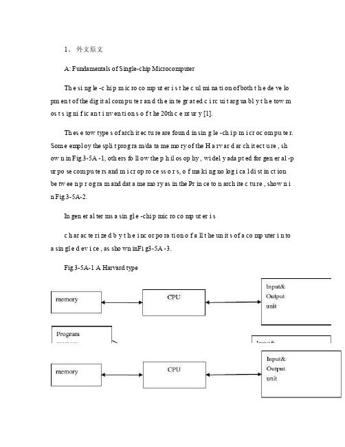
1、外文原文A: Fundamentals of Single-chip MicrocomputerTh e si ng le -c hi p m ic ro co mp ut er i s t he c ul mi na ti on of both t h e de ve lo pm en t of the dig it al com pu te r an d th e in te gr at ed c i rc ui t arg ua bl y t h e tow m os t s ig ni f ic an t i nv en ti on s o f t he 20th c e nt ur y [1].Th es e tow type s of arch it ec tu re are foun d in sin g le -ch i p m i cr oc om pu te r. Som e empl oy the spli t prog ra m/da ta me mo ry of the H a rv ar d ar ch it ect u re , sh ow n in Fig.3-5A -1, oth ers fo ll ow the p h il os op hy , wi del y ada pt ed for gen er al -p ur po se com pu te rs and m i cr op ro ce ss o r s, o f ma ki ng no log i ca l di st in ct ion be tw ee n p r og ra m and dat a me mo ry as in the Pr in ce to n arch ite c tu re , show n i n Fig.3-5A-2.In gen er al ter ms a sin gl e -chi p mic ro co mp ut er i sc h ar ac te ri zed b y t he i nc or po ra ti on of a ll t he un it s of a co mp uter i n to a sin gl e d ev i ce , as sho wn inFi g3-5A -3.Fig.3-5A-1 A Harvard typeFig.3-5A-2. A conventional Princeton computerFig3-5A-3. Principal features of a microcomputerRead only memory (ROM.R OM is usua ll y for the pe rm an ent,n o n-vo la ti le stor a ge of an app lic a ti on s pr og ra m .M an ym i cr oc om pu te rs and m are inte nd e d for high -v ol um e ap pl ic at ions a n d he nc e t h e eco n om ic al man uf act u re of th e de vic e s re qu ir es t h at t he cont en t s o f t he prog ra m me m or y be co mm it t ed perm a ne ntly d u ri ng the man ufa c tu re of ch ip s .Cl ea rl y, thi s im pl ie s a r i go ro us app ro ach to ROM cod e deve l op me nt sin ce cha ng es can not b e mad e afte r manu f a c tu re .Th is dev e lo pm en t proc ess may invo lv e e m ul at io n us in g aso ph is ti ca te d de ve lo pm en t sy ste m wit h a h a rd wa re emu la tio n cap ab il it y as w el l as the use o f po we rf ul s o ft wa re too ls.So me man uf act u re rs pro vi de add it io na l RO M opt i on s by i n cl ud in g in their ra n ge dev ic es wit h (or int en de d fo r use wit h u s er pro gr am ma ble me mo ry. Th e sim p le st of th es e is usu al ly d e vi ce whi ch can op er at e in a micro p ro ce ssor mod e by usi ng som e o f the inp ut /outp u t li ne s as an ad dr es s an d da ta b us fora c ce ss in g ex te rna l mem or y. Thi s t y pe of de vi ce can beh av ef u nc ti on al ly as th e sing le chip mi cr oc om pu te r from whi ch it is d e ri ve d al be it wit h re st ri ct ed I/O and a mod if ied ex te rn al c i rc ui t. The use of thes e d ev ic es is com mo n eve n in prod uc ti on c i rc ui ts wher e t he vo lu me does no tj us ti f y t h e d ev el o pm en t c osts o f c us to m o n -ch i p R OM [2];t he re c a n s ti ll bea s ignif i ca nt saving i n I /O and o th er c h ip s com pa re d to a conv en ti on al mi c ro pr oc es sor b a se d ci rc ui t. Mor e ex ac t re pl ace m en t fo r RO M dev i ce s ca n be o b ta in ed in th e fo rm of va ri an ts w it h 'p ig gy -b ack 'E P RO M(Er as ab le pro gr am ma bl e ROM s oc ke ts or dev ic e s with EPROM i n st ea d o f RO M 。
断路器中英文对照外文翻译文献

中英文对照外文翻译文献(文档含英文原文和中文翻译)外文文献:Circuit BreaksWithin a few years of the introduction of the fuse,the growing electrical industry started looking for an alternative method of providing protection for electric circuits.They wanted a device that would not bedestroyed by its operation,that could simply be reset to restore power, and that could also be used as a means of switching for the circuit.Out of this development work came the circuit breaker.which is an electromechanical device.The circuit breaker is defined as a device designed to open and close a circuit by non-automatic means and to open the circuit automatically on a predetermined over-current without injure to itself when properly applied within its rating.As with other equipment,circuit breakers are divided into those rated for 1 000 volts and less and those rated for more than 1000 volts.Low-voltage circuit breakers were also divided into two distinct categories,molded-case and power types.However,in the past few years the distinction between these two types has become less clea-cut as a new type of encased breaker are universally operated in air, so it is not necessary to designate them as air circuit breakers as this understood.Medium and high—voltage breakers,on the other hand,use mediums other than air in which to open the circuit and therefore must be designated as being air, gas,and so on.Apart from having different voltage and continuous currentratings.breakers have widely different interrupting ratings,response characteristics,and methods of operation.The proper application of circuit breakers requires a good knowledge of all the characteristics and options available for each type.The simplest circuit—opening device is the manually operated knife switch.This switch has the basic parts required of any circuit—opening device:a fixed contact, a moving,an operating handle,and a base—plate or flame.However as anyone who has opened a knife switch under load has witnessed,there is a luminous discharge drawn between the separating contacts of the switch.This discharge is called an arc,and it consists of a stream of positive and negative ions. The current flowing in a circuit cannot be instantaneously interrupted.As a result,the arc continues until the switch contacts have separated far enough to finally extinguish the arc.The arc can make the opening of the switch very unsafe and unreliable when interrupting a circuit breaker must provide a safer and more reliable interrupting action. The following are the means by witch low—voltage circuit breakers can be made to safely interrupt large faultcurrents with a minimum of contact damage.1.Fast speed of operation.The duration and severity of an arc depends in part on the speed with witch the contacts can be separated,therefore powerful spring are used to rapidly force the contacts open.These springs are compressed (charged)during the closing operation.The breaker contacts are then mechanically held closed and are released by a separate trip mechanism.An operator can initiate the opening of the breaker but has no control over the speed with which the contacts separate.2.Use of arcing contacts.The arc burn can cause pitting,which eventually affects the ability of the contacts to carry the load current when closed.To offset this, two parallel sets of contacts are used for each pole of the breaker,a main current carrying set and an auxiliary or arcing set.When the breaker is tripped open, the main contacts separate first,transferring the current flow to the arcing contacts.The arcing contacts then separate a split second late,drawing the arc between them and leaving the main contacts free of any arcing.This allows the surfaces of the main current carrying contacts to be made of high—conductivitymetal such as silver,the surfaces of the arcing contacts are then made of a tougher alloy better able to withstand the effects of arcing.3.Use of arc chutes Parallel plates enclosed in the form of a chute are mounted directly above the arcing contacts.As the arcing contacts separate, the resulting are creates a strong magnetic field that forces the arc upward into the plates.The arc stream is then broken into a series of small arcs,which are quickly cooled,deionized,and extinguished.The ionized gases created by the are stream must be deionized before they are expelled from the arc chute;otherwise,secondary arcing could occur between the line side terminals of the breaker, which are still energized.中文译文:断路器在引入保险丝的这几年,电气行业开始寻找一种保护电路的替代方法。
电气工程及其自动化专业 外文文献 英文文献 外文翻译 plc方面

1、外文原文(复印件)A: Fundamentals of Single-chip MicrocomputerTh e si ng le-ch i p mi cr oc om pu ter is t he c ul mi nat i on o f bo th t h e d ev el op me nt o f th e d ig it al com p ut er an d t he int e gr at ed ci rc ui ta r gu ab ly th e t ow m os t s i gn if ic ant i nv en ti on s o f t h e 20t h c en tu ry[1].Th es e to w typ e s of a rc hi te ctu r e ar e fo un d i n s in gl e-ch ip m i cr oc om pu te r. So m e em pl oy t he sp l it p ro gr am/d ata me mo ry o f th e H a rv ar d ar ch it ect u re, sh ow n i n -5A, ot he rs fo ll ow th e ph i lo so ph y, w i de ly a da pt ed fo r g en er al-p ur pos e c om pu te rs an d m i cr op ro ce ss or s, o f m a ki ng no lo gi c al di st in ct io n b e tw ee n p ro gr am a n d da t a m em ory a s i n th e Pr in cet o n ar ch it ec tu re,sh ow n in-5A.In g en er al te r ms a s in gl e-chi p m ic ro co mp ut er i sc h ar ac te ri zed b y the i nc or po ra tio n of al l t he uni t s o f a co mp ut er i n to a s in gl e dev i ce, as s ho wn in Fi g3-5A-3.-5A-1 A Harvard type-5A. A conventional Princeton computerFig3-5A-3. Principal features of a microcomputerRead only memory (ROM).R OM i s u su al ly f or th e p er ma ne nt, n o n-vo la ti le s tor a ge o f an a pp lic a ti on s pr og ra m .M an ym i cr oc om pu te rs an d mi cr oc on tr ol le r s a re in t en de d fo r h ig h-v ol ume a p pl ic at io ns a nd h en ce t he e co nom i ca l ma nu fa ct ure of t he d ev ic es r e qu ir es t ha t the co nt en ts o f the pr og ra m me mo ry b e co mm it te dp e rm an en tl y d ur in g th e m an uf ac tu re o f c hi ps . Cl ear l y, th is im pl ie sa ri g or ou s a pp roa c h t o R OM co de d e ve lo pm en t s in ce c ha ng es ca nn otb e m ad e af te r man u fa ct ur e .T hi s d e ve lo pm en t pr oce s s ma y in vo lv e e m ul at io n us in g a s op hi st ic at ed deve lo pm en t sy st em w i th a ha rd wa re e m ul at io n ca pa bil i ty a s we ll a s th e u se of po we rf ul so ft wa re t oo ls.So me m an uf act u re rs p ro vi de ad d it io na l RO M opt i on s byi n cl ud in g i n th ei r ra ng e de vi ce s wi th (or i nt en de d fo r us e wi th) u s er pr og ra mm ab le m em or y. Th e s im p le st of th es e i s us ua ll y d ev ice w h ic h ca n op er ate in a m ic ro pr oce s so r mo de b y usi n g so me o f th e i n pu t/ou tp ut li ne s as a n ad dr es s an d da ta b us f or acc e ss in g e xt er na l m e mo ry. T hi s t ype o f d ev ic e c an b e ha ve fu nc ti on al l y a s t he si ng le c h ip mi cr oc om pu te r fr om wh ic h i t i s de ri ve d a lb eit w it h r es tr ic ted I/O an d a mo di fie d e xt er na l ci rcu i t. T he u se o f t h es e RO Ml es sd e vi ce s is c om mo n e ve n in p ro du ct io n c ir cu it s wh er e t he v ol um e do es n o t ju st if y th e d e ve lo pm en t co sts of c us to m on-ch i p RO M[2];t he re c a n st il l b e a si g ni fi ca nt s a vi ng in I/O a nd ot he r c hi ps co mp ar ed t o a c on ve nt io nal mi cr op ro ce ss or b as ed c ir cu it. M o re e xa ctr e pl ac em en t fo r RO M d ev ic es c an b e o bt ai ne d in t he f o rm o f va ri an ts w i th 'pi gg y-ba ck'EP RO M(Er as ab le p ro gr am ma bl e ROM)s oc ke ts o rd e vi ce s w it h EP ROM i ns te ad o f R OM 。
电气 自动化 外文文献 外文翻译 英文文献
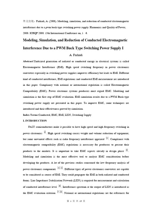
外文出处:Farhadi, A. (2008). Modeling, simulation, and reduction of conducted electromagnetic interference due to a pwm buck type switching power supply. Harmonics and Quality of Power, 2008. ICHQP 2008. 13th International Conference on, 1 - 6.Modeling, Simulation, and Reduction of Conducted Electromagnetic Interference Due to a PWM Buck Type Switching Power Supply IA. FarhadiAbstract:Undesired generation of radiated or conducted energy in electrical systems is called Electromagnetic Interference (EMI). High speed switching frequency in power electronics converters especially in switching power supplies improves efficiency but leads to EMI. Different kind of conducted interference, EMI regulations and conducted EMI measurement are introduced in this paper. Compliancy with national or international regulation is called Electromagnetic Compatibility (EMC). Power electronic systems producers must regard EMC. Modeling and simulation is the first step of EMC evaluation. EMI simulation results due to a PWM Buck type switching power supply are presented in this paper. To improve EMC, some techniques are introduced and their effectiveness proved by simulation.Index Terms:Conducted, EMC, EMI, LISN, Switching SupplyI. INTRODUCTIONFAST semiconductors make it possible to have high speed and high frequency switching in power electronics []1. High speed switching causes weight and volume reduction of equipment, but some unwanted effects such as radio frequency interference appeared []2. Compliance with electromagnetic compatibility (EMC) regulations is necessary for producers to present their products to the markets. It is important to take EMC aspects already in design phase []3. Modeling and simulation is the most effective tool to analyze EMC consideration before developing the products. A lot of the previous studies concerned the low frequency analysis of power electronics components []4[]5. Different types of power electronics converters are capable to be considered as source of EMI. They could propagate the EMI in both radiated and conducted forms. Line Impedance Stabilization Network (LISN) is required for measurement and calculation of conducted interference level []6. Interference spectrum at the output of LISN is introduced as the EMC evaluation criterion []7[]8. National or international regulations are the references forthe evaluation of equipment in point of view of EMC []7[]8.II. SOURCE, PATH AND VICTIM OF EMIUndesired voltage or current is called interference and their cause is called interference source. In this paper a high-speed switching power supply is the source of interference.Interference propagated by radiation in area around of an interference source or by conduction through common cabling or wiring connections. In this study conducted emission is considered only. Equipment such as computers, receivers, amplifiers, industrial controllers, etc that are exposed to interference corruption are called victims. The common connections of elements, source lines and cabling provide paths for conducted noise or interference. Electromagnetic conducted interference has two components as differential mode and common mode []9.A. Differential mode conducted interferenceThis mode is related to the noise that is imposed between different lines of a test circuit by a noise source. Related current path is shown in Fig. 1 []9. The interference source, path impedances, differential mode current and load impedance are also shown in Fig. 1.B. Common mode conducted interferenceCommon mode noise or interference could appear and impose between the lines, cables or connections and common ground. Any leakage current between load and common ground couldbe modeled by interference voltage source.Fig. 2 demonstrates the common mode interference source, common mode currents Iandcm1 and the related current paths[]9.The power electronics converters perform as noise source Icm2between lines of the supply network. In this study differential mode of conducted interference is particularly important and discussion will be continued considering this mode only.III. ELECTROMAGNETIC COMPATIBILITY REGULATIONS Application of electrical equipment especially static power electronic converters in different equipment is increasing more and more. As mentioned before, power electronics converters are considered as an important source of electromagnetic interference and have corrupting effects on the electric networks []2. High level of pollution resulting from various disturbances reduces the quality of power in electric networks. On the other side some residential, commercial and especially medical consumers are so sensitive to power system disturbances including voltage and frequency variations. The best solution to reduce corruption and improve power quality is complying national or international EMC regulations. CISPR, IEC, FCC and VDE are among the most famous organizations from Europe, USA and Germany who are responsible for determining and publishing the most important EMC regulations. IEC and VDE requirement and limitations on conducted emission are shown in Fig. 3 and Fig. 4 []7[]9.For different groups of consumers different classes of regulations could be complied. Class Afor common consumers and class B with more hard limitations for special consumers are separated in Fig. 3 and Fig. 4. Frequency range of limitation is different for IEC and VDE that are 150 kHz up to 30 MHz and 10 kHz up to 30 MHz respectively. Compliance of regulations is evaluated by comparison of measured or calculated conducted interference level in the mentioned frequency range with the stated requirements in regulations. In united European community compliance of regulation is mandatory and products must have certified label to show covering of requirements []8.IV. ELECTROMAGNETIC CONDUCTED INTERFERENCE MEASUREMENTA. Line Impedance Stabilization Network (LISN)1-Providing a low impedance path to transfer power from source to power electronics converter and load.2-Providing a low impedance path from interference source, here power electronics converter, to measurement port.Variation of LISN impedance versus frequency with the mentioned topology is presented inFig. 7. LISN has stabilized impedance in the range of conducted EMI measurement []7.Variation of level of signal at the output of LISN versus frequency is the spectrum of interference. The electromagnetic compatibility of a system can be evaluated by comparison of its interference spectrum with the standard limitations. The level of signal at the output of LISN in frequency range 10 kHz up to 30 MHz or 150 kHz up to 30 MHz is criterion of compatibility and should be under the standard limitations. In practical situations, the LISN output is connected to a spectrum analyzer and interference measurement is carried out. But for modeling and simulation purposes, the LISN output spectrum is calculated using appropriate software.基于压降型PWM开关电源的建模、仿真和减少传导性电磁干扰摘要:电子设备之中杂乱的辐射或者能量叫做电磁干扰(EMI)。
电气工程的外文文献(及翻译)
电气工程的外文文献(及翻译)文献一:Electric power consumption prediction model based on grey theory optimized by genetic algorithms本文介绍了一种基于混合灰色理论与遗传算法优化的电力消耗预测模型。
该模型使用时间序列数据来建立模型,并使用灰色理论来解决数据的不确定性问题。
通过遗传算法的优化,模型能够更好地预测电力消耗,并取得了优异的预测结果。
此模型可以在大规模电力网络中使用,并具有较高的可行性和可靠性。
文献二:Intelligent control for energy-efficient operation of electric motors本文研究了一种智能控制方法,用于电动机的节能运行。
该方法提供了一种更高效的控制策略,使电动机能够在不同负载条件下以较低的功率运行。
该智能控制使用模糊逻辑方法来确定最佳的控制参数,并使用遗传算法来优化参数。
实验结果表明,该智能控制方法可以显著降低电动机的能耗,节省电能。
文献三:Fault diagnosis system for power transformers based on dissolved gas analysis本文介绍了一种基于溶解气体分析的电力变压器故障诊断系统。
通过对变压器油中的气体样品进行分析,可以检测和诊断变压器内部存在的故障类型。
该系统使用人工神经网络模型来对气体分析数据进行处理和分类。
实验结果表明,该系统可以准确地检测和诊断变压器的故障,并有助于实现有效的维护和管理。
文献四:Power quality improvement using series active filter based on iterative learning control technique本文研究了一种基于迭代研究控制技术的串联有源滤波器用于电能质量改善的方法。
智能控制系统毕业论文中英文资料对照外文翻译文献
智能控制系统中英文资料对照外文翻译文献附录一:外文摘要The development and application of Intelligence controlsystemModern electronic products change rapidly is increasingly profound impact on people's lives, to people's life and working way to bring more convenience to our daily lives, all aspects of electronic products in the shadow, single chip as one of the most important applications, in many ways it has the inestimable role. Intelligent control is a single chip, intelligent control of applications and prospects are very broad, the use of modern technology tools to develop an intelligent, relatively complete functional software to achieve intelligent control system has become an imminent task. Especially in today with MCU based intelligent control technology in the era, to establish their own practical control system has a far-reaching significance so well on the subject later more fully understanding of SCM are of great help to.The so-called intelligent monitoring technology is that:" the automatic analysis and processing of the information of the monitored device". If the monitored object as one's field of vision, and intelligent monitoring equipment can be regarded as the human brain. Intelligent monitoring with the aid of computer data processing capacity of the powerful, to get information in the mass data to carry on the analysis, some filtering of irrelevant information, only provide some key information. Intelligent control to digital, intelligent basis, timely detection system in the abnormal condition, and can be the fastest and best way to sound the alarm and provide usefulinformation, which can more effectively assist the security personnel to deal with the crisis, and minimize the damage and loss, it has great practical significance, some risk homework, or artificial unable to complete the operation, can be used to realize intelligent device, which solves a lot of artificial can not solve the problem, I think, with the development of the society, intelligent load in all aspects of social life play an important reuse.Single chip microcomputer as the core of control and monitoring systems, the system structure, design thought, design method and the traditional control system has essential distinction. In the traditional control or monitoring system, control or monitoring parameters of circuit, through the mechanical device directly to the monitored parameters to regulate and control, in the single-chip microcomputer as the core of the control system, the control parameters and controlled parameters are not directly change, but the control parameter is transformed into a digital signal input to the microcontroller, the microcontroller according to its output signal to control the controlled object, as intelligent load monitoring test, is the use of single-chip I / O port output signal of relay control, then the load to control or monitor, thus similar to any one single chip control system structure, often simplified to input part, an output part and an electronic control unit ( ECU )Intelligent monitoring system design principle function as follows: the power supply module is 0~220V AC voltage into a0 ~ 5V DC low voltage, as each module to provide normal working voltage, another set of ADC module work limit voltage of 5V, if the input voltage is greater than 5V, it can not work normally ( but the design is provided for the load voltage in the 0~ 5V, so it will not be considered ), at the same time transformer on load current is sampled on the accused, the load current into a voltage signal, and then through the current - voltage conversion, and passes through the bridge rectification into stable voltage value, will realize the load the current value is converted to a single chip can handle0 ~ 5V voltage value, then the D2diode cutoff, power supply module only plays the role of power supply. Signal to the analog-to-digital conversion module, through quantization, coding, the analog voltage value into8bits of the digital voltage value, repeatedly to the analog voltage16AD conversion, and the16the digital voltage value and, to calculate the average value, the average value through a data bus to send AT89C51P0, accepted AT89C51 read, AT89C51will read the digital signal and software setting load normal working voltage reference range [VMIN, VMAX] compared with the reference voltage range, if not consistent, then the P1.0 output low level, close the relay, cut off the load on the fault source, to stop its sampling, while P1.1 output high level fault light, i.e., P1.3 output low level, namely normal lights. The relay is disconnected after about 2minutes, theAT89C51P1.0outputs high level ( software design), automatic closing relay, then to load the current regular sampling, AD conversion, to accept the AT89C51read, comparison, if consistent, then the P1.1 output low level, namely fault lights out, while P1.3 output high level, i.e. normal lamp ( software set ); if you are still inconsistent, then the need to manually switch S1toss to" repair" the slip, disconnect the relay control, load adjusting the resistance value is: the load detection and repair, and then close the S1repeatedly to the load current sampling, until the normal lamp bright, repeated this process, constantly on the load testing to ensure the load problems timely repair, make it work.In the intelligent load monitoring system, using the monolithic integrated circuit to the load ( voltage too high or too small ) intelligent detection and control, is achieved by controlling the relay and transformer sampling to achieve, in fact direct control of single-chip is the working state of the relay and the alarm circuit working state, the system should achieve technical features of this thesis are as follows (1) according to the load current changes to control relays, the control parameter is the load current, is the control parameter is the relay switch on-off and led the state; (2) the set current reference voltage range ( load normal working voltage range ), by AT89C51 chip the design of the software section, provide a basis for comparison; (3) the use of single-chip microcomputer to control the light-emitting diode to display the current state of change ( normal / fault / repair ); specific summary: Transformer on load current is sampled, a current / voltage converter, filter, regulator, through the analog-digital conversion, to accept the AT89C51chip to read, AT89C51 to read data is compared with the reference voltage, if normal, the normal light, the output port P.0high level, the relay is closed, is provided to the load voltage fault light; otherwise, P1.0 output low level, The disconnecting relay to disconnect the load, the voltage on the sampling, stop. Two minutes after closing relay, timing sampling.System through the expansion of improved, can be used for temperature alarm circuit, alarm circuit, traffic monitoring, can also be used to monitor a system works, in the intelligent high-speed development today, the use of modern technology tools, the development of an intelligent, function relatively complete software to realize intelligent control system, has become an imminent task, establish their own practical control system has a far-reaching significance. Micro controller in the industry design and application, no industry like intelligent automation and control field develop so fast. Since China and the Asian region the main manufacturing plant intelligence to improve the degree of automation, new technology to improve efficiency, have important influence on the product cost. Although the centralized control can be improved in any particular manufacturing process of the overall visual, but not for those response and processingdelay caused by fault of some key application.Intelligent control technology as computer technology is an important technology, widely used in industrial control, intelligent control, instrument, household appliances, electronic toys and other fields, it has small, multiple functions, low price, convenient use, the advantages of a flexible system design. Therefore, more and more engineering staff of all ages, so this graduate design is of great significance to the design of various things, I have great interest in design, this has brought me a lot of things, let me from unsuspectingly to have a clear train of thought, since both design something, I will be there a how to design thinking, this is very important, I think this job will give me a lot of valuable things.中文翻译:智能控制系统的开发应用现代社会电子产品日新月异正在越来越深远的影响着人们的生活,给人们的生活和工作方式带来越来越大的方便,我们的日常生活各个方面都有电子产品的影子,单片机作为其中一个最重要的应用,在很多方面都有着不可估量的作用。
断路器中英文对照外文翻译文献
中英文对照外文翻译文献(文档含英文原文和中文翻译)外文文献:Circuit BreaksWithin a few years of the introduction of the fuse,the growing electrical industry started looking for an alternative method of providing protection for electric circuits.They wanted a device that would not bedestroyed by its operation,that could simply be reset to restore power, and that could also be used as a means of switching for the circuit.Out of this development work came the circuit breaker.which is an electromechanical device.The circuit breaker is defined as a device designed to open and close a circuit by non-automatic means and to open the circuit automatically on a predetermined over-current without injure to itself when properly applied within its rating.As with other equipment,circuit breakers are divided into those rated for 1 000 volts and less and those rated for more than 1000 volts.Low-voltage circuit breakers were also divided into two distinct categories,molded-case and power types.However,in the past few years the distinction between these two types has become less clea-cut as a new type of encased breaker are universally operated in air, so it is not necessary to designate them as air circuit breakers as this understood.Medium and high—voltage breakers,on the other hand,use mediums other than air in which to open the circuit and therefore must be designated as being air, gas,and so on.Apart from having different voltage and continuous currentratings.breakers have widely different interrupting ratings,response characteristics,and methods of operation.The proper application of circuit breakers requires a good knowledge of all the characteristics and options available for each type.The simplest circuit—opening device is the manually operated knife switch.This switch has the basic parts required of any circuit—opening device:a fixed contact, a moving,an operating handle,and a base—plate or flame.However as anyone who has opened a knife switch under load has witnessed,there is a luminous discharge drawn between the separating contacts of the switch.This discharge is called an arc,and it consists of a stream of positive and negative ions. The current flowing in a circuit cannot be instantaneously interrupted.As a result,the arc continues until the switch contacts have separated far enough to finally extinguish the arc.The arc can make the opening of the switch very unsafe and unreliable when interrupting a circuit breaker must provide a safer and more reliable interrupting action. The following are the means by witch low—voltage circuit breakers can be made to safely interrupt large faultcurrents with a minimum of contact damage.1.Fast speed of operation.The duration and severity of an arc depends in part on the speed with witch the contacts can be separated,therefore powerful spring are used to rapidly force the contacts open.These springs are compressed (charged)during the closing operation.The breaker contacts are then mechanically held closed and are released by a separate trip mechanism.An operator can initiate the opening of the breaker but has no control over the speed with which the contacts separate.2.Use of arcing contacts.The arc burn can cause pitting,which eventually affects the ability of the contacts to carry the load current when closed.To offset this, two parallel sets of contacts are used for each pole of the breaker,a main current carrying set and an auxiliary or arcing set.When the breaker is tripped open, the main contacts separate first,transferring the current flow to the arcing contacts.The arcing contacts then separate a split second late,drawing the arc between them and leaving the main contacts free of any arcing.This allows the surfaces of the main current carrying contacts to be made of high—conductivitymetal such as silver,the surfaces of the arcing contacts are then made of a tougher alloy better able to withstand the effects of arcing.3.Use of arc chutes Parallel plates enclosed in the form of a chute are mounted directly above the arcing contacts.As the arcing contacts separate, the resulting are creates a strong magnetic field that forces the arc upward into the plates.The arc stream is then broken into a series of small arcs,which are quickly cooled,deionized,and extinguished.The ionized gases created by the are stream must be deionized before they are expelled from the arc chute;otherwise,secondary arcing could occur between the line side terminals of the breaker, which are still energized.中文译文:断路器在引入保险丝的这几年,电气行业开始寻找一种保护电路的替代方法。
电气工程及其自动化 外文翻译 外文文献 英文文献 电力系统的简介
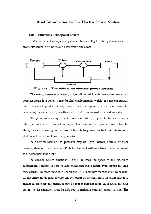
Brief Introduction to The Electric Power SystemPart 1 Minimum electric power systemA minimum electric power system is shown in Fig.1-1, the system consists of an energy source, a prime mover, a generator, and a load.The energy source may be coal, gas, or oil burned in a furnace to heat water and generate steam in a boiler; it may be fissionable material which, in a nuclear reactor, will heat water to produce steam; it may be water in a pond at an elevation above the generating station; or it may be oil or gas burned in an internal combustion engine.The prime mover may be a steam-driven turbine, a hydraulic turbine or water wheel, or an internal combustion engine. Each one of these prime movers has the ability to convert energy in the form of heat, falling water, or fuel into rotation of a shaft, which in turn will drive the generator.The electrical load on the generator may be lights, motors, heaters, or other devices, alone or in combination. Probably the load will vary from minute to minute as different demands occur.The control system functions (are)to keep the speed of the machines substantially constant and the voltage within prescribed limits, even though the load may change. To meet these load conditions, it is necessary for fuel input to change, for the prime mover input to vary, and for torque on the shaft from the prime mover to change in order that the generator may be kept at constant speed. In addition, the field current to the generator must be adjusted to maintain constant output voltage. Thecontrol system may include a man stationed in the power plant who watches a set of meters on the generator output terminals and makes the necessary adjustments manually. In a modern station, the control system is a servomechanism that senses generator-output conditions and automatically makes the necessary changes in energy input and field current to hold the electrical output within certain specifications..Part 2 More Complicated SystemsIn most situations the load is not directly connected to the generator terminals. More commonly the load is some distance from the generator, requiring a power line connecting them. It is desirable to keep the electric power supply at the load within specifications. However, the controls are near the generator, which may be in another building, perhaps several miles away.If the distance from the generator to the load is considerable, it may be desirable to install transformers at the generator and at the load end, and to transmit the power over a high-voltage line (Fig.1-2). For the same power, the higher-voltage line carries less current, has lower losses for the same wire size, and provides more stable voltage.In some cases an overhead line may be unacceptable. Instead it may be advantageous to use an underground cable. With the power systems talked above, the power supply to the load must be interrupted if, for any reason, any component of the system must be moved from service for maintenance or repair. Additional system load may require more power than the generator can supply. Another generator with its associated transformers and high-voltage line might be added.It can be shown that there are some advantages in making ties between the generators (1) and at the end of the high-voltage lines (2 and 3), as shown in Fig.1-3. This system will operate satisfactorily as long as no trouble develops or no equipmentneeds to be taken out of service.The above system may be vastly improved by the introduction of circuit breakers, which may be opened and closed as needed. Circuit breakers added to the system, Fig.1-4, permit selected piece of equipment to switch out of service without disturbing the remainder of system. With this arrangement any element of the system may be deenergized for maintenance or repair by operation of circuit breakers.Of course, if any piece of equipment is taken out of service, then the total load must be carried by the remaining equipment. Attention must be given to avoid overloads during such circumstances. If possible, outages of equipment are scheduled at times when load requirements are below normal.Fig.1-5 shows a system in which three generators and three loads are tied together by three transmission lines. No circuit breakers are shown in this diagram, although many would be required in such a system.Part 3 Typical System LayoutThe generators, lines, and other equipment which form an electric system are arranged depending on the manner in which load grows in the area and may be rearranged from time to time.However, there are certain plans into which a particular system design may be classified. Three types are illustrated: the radial system, the loop system, and the network system. All of these are shown without the necessary circuit breakers. In each of these systems, a single generator serves four loads.The radial system is shown in Fig.1-6. Here the lines form a “tree” spreading out from the generator. Opening any line results in interruption of power to one or more of the loads.The loop system is illustrated in Fig.1-7. With this arrangement all loads may be served even though one line section is removed from service. In some instances during normal operation, the loop may be open at some point, such as A. In case a line section is to be taken out, the loop is first closed at A and then the line section removed. In this manner no service interruptions occur.Fig.1-8 shows the same loads being served by a network. With this arrangement each load has two or more circuits over which it is fed.Distribution circuits are commonly designed so that they may be classified as radial or loop circuits. The high-voltage transmission lines of most power systems are arranged as network. The interconnection of major power system results in networks made up by many line sections.Part 4 Auxiliary EquipmentCircuit breakers are necessary to deenergize equipment either for normal operation or on the occurrence of short circuits. Circuit breakers must be designed to carry normal-load currents continuously, to withstand the extremely high currents that occur during faults, and to separate contacts and clear a circuit in the presence of fault. Circuit breakers are rated in terms of these duties.When a circuit breaker opens to deenergize a piece of equipment, one side of the circuit breaker usually remains energized, as it is connected to operating equipment. Since it is sometimes necessary to work on the circuit breaker itself, it is also necessary to have means by which the circuit breaker may be completely disconnected from other energized equipment. For this purpose disconnect switches are placed in series with the circuit breakers. By opening these disconnectors, thecircuit breaker may be completely deenergized, permitting work to be carried on in safety.Various instruments are necessary to monitor the operation of the electric power system. Usually each generator, each transformer bank, and each line has its own set of instruments, frequently consisting of voltmeters, ammeters, wattmeters, and varmeters.When a fault occurs on a system, conditions on the system undergo a sudden change. V oltages usually drop and currents increase. These changes are most noticeable in the immediate vicinity of fault. On-line analog computers, commonly called relays, monitor these changes of conditions, make a determination of which breaker should be opened to clear the fault, and energize the trip circuits of those appropriate breakers. With modern equipment, the relay action and breaker opening causes removal of fault within three or four cycles after its initiation.The instruments that show circuit conditions and the relays that protect the circuits are not mounted directly on the power lines but are placed on switchboards in a control house. Instrument transformers are installed on the high-voltage equipment, by means of which it is possible to pass on to the meters and relays representative samples of the conditions on the operating equipment. The primary of a potential transformer is connected directly to the high-voltage equipment. The secondary provides for the instruments and relays a voltage which is a constant fraction of voltage on the operating equipment and is in phase with it;similarly, a current transformer is connected with its primary in the high-current circuit. The secondary winding provides a current that is a known fraction of the power-equipment current and is in phase with it.Bushing potential devices and capacitor potential devices serve the same purpose as potential transformers but usually with less accuracy in regard to ratio and phase angle.中文翻译:电力系统的简介第一部分:最小电力系统一个最小电力系统如图1-1所示,系统包含动力源,原动机,发电机和负载。
汽车电子系统中英文对照外文翻译文献
汽车电子系统中英文对照外文翻译文献汽车电子系统中英文对照外文翻译文献1汽车电子系统中英文对照外文翻译文献(文档含英文原文和中文翻译)The Changing Automotive Environment: High-Temperature ElectronicsR. Wayne Johnson, Fellow, IEEE, John L. Evans, Peter Jacobsen, James R. (Rick) Thompson, and Mark ChristopherAbstract —The underhood automotive environment is harsh and current trends in the automotive electronics industry will be pushing the temperatureenvelope for electronic components. The desire to place engine control unitson the engine and transmission control units either on or in the transmissionwill push the ambient temperature above 125125℃℃.However, extreme cost pressures,increasing reliability demands (10 year/241 350 km) and the cost of field failures (recalls, liability, customer loyalty) will make the shift to higher temperatures occur incrementally. The coolest spots on engine and in the transmission will be used. These large bodies do provide considerableheat sinking to reduce temperature rise due to power dissipation in the controlunit. The majority of near term applications will be at 150 ℃ or less andthese will be worst case temperatures, not nominal. The transition toX-by-wire technology, replacing mechanical and hydraulic systems with electromechanical systems will require more power electronics. Integrationof power transistors and smart power devices into the electromechanical℃ to 200℃ . Hybridactuator will require power devices to operate at 175electric vehicles and fuel cell vehicles will also drive the demand for higher temperature power electronics. In the case of hybrid electric and fuel cell vehicles, the high temperature will be due to power dissipation. Thealternates to high-temperature devices are thermal management systems which add weight and cost. Finally, the number of sensors in vehicles is increasingas more electrically controlled systems are added. Many of these sensors mustwork in high-temperature environments. The harshest applications are exhaustgas sensors and cylinder pressure or combustion sensors. High-temperature electronics use in automotive systems will continue to grow, but it will be gradual as cost and reliability issues are addressed. This paper examines themotivation for higher temperature operation,the packaging limitations evenat 125 C with newer package styles and concludes with a review of challenge at both the semiconductor device and packaging level as temperatures push beyond 125 ℃.Index Terms—Automotive, extreme-environment electronics.I. INTRODUCTIONI N 1977, the average automobile contained $110 worth of electronics [1]. By 2003 the electronics content was $1510 per vehicle and is expected to reach$2285 in 2013 [2].The turning point in automotive electronics was governmentTABLE IMAJOR AUTOMOTIVE ELECTRONIC SYSTEMSTABLE IIAUTOMOTIVETEMPERATUREEXTREMES(DELPHIDELCOELECTRONIC SYSTEMS) [3]regulation in the 1970s mandating emissions control and fuel economy. The complex fuel control required could not be accomplished using traditional mechanical systems. These government regulations coupled with increasing semiconductor computing power at decreasing cost have led to an ever increasing array of automotive electronics. Automotive electronics can be divided into five major categories as shown in Table I.The operating temperature of the electronics is a function of location, power dissipation by the electronics, and the thermal design. The automotive electronics industry defines high-temperature electronics as electronics operating above 125 ℃. However, the actual temperature for various electronics mounting locations varies considerably. Delphi Delco Electronic Systems recently published the typical continuous maximum temperatures as reproduced in Table II [3]. The corresponding underhood temperatures are shown in Fig. 1. The authors note that typical junction temperatures for integrated circuits are 10 ℃to15℃ higher than ambient or baseplate temperature, while power devices can reach 25 ℃ higher. At-engine temperatures of 125℃ peak can be maintained by placing the electronics on theintake manifold.Fig. 1. Engine compartment thermal profile (Delphi Delco Electronic Systems) [3].TABLE III THEAUTOMOTIVEENVIRONMENT(GENERALMOTORS ANDDELPHIDELCO ELECTRONICSYSTEMS) [4]TABLE IV REQUIREDOPERATIONTEMPERATURE FORAUTOMOTIVEELECTRONIC SYSTEMS(TOYOTAMOTORCORP. [5]TABLE VMECHA TRONICMAXIMUMTEMPERA TURERANGES(DAIMLERCHRYSLER,EA TONCORPORA TION, ANDAUBURNUNIVERSITY) [6]Fig. 2. Automotive temperatures and related systems (DaimlerChrysler) [8].automotive electronic systems [8]. Fig. 3 shows an actual measured transmission transmission temperature temperature temperature profile profile profile during during during normal normal normal and and excessive excessive driving drivingconditions [8]. Power braking is a commonly used test condition where the brakes are applied and the engine is revved with the transmission in gear.A similar real-world situation would be applying throttle with the emergencybrake applied. Note that when the temperature reached 135135℃℃,the over temperature light came on and at the peak temperature of 145145℃℃,the transmission was beginning to smell of burnt transmission fluid.TABLE VI2002I NTERNA TIONAL T ECHNOLOGY R OADMAPFOR S EMICONDUCTORS A MBI ENTOPERA TINGTEMPERA TURES FORHARSHENVIRONMENTS (AUTOMOTIVE) [9]The 2002 update to the International Technology Roadmap for Semiconductors (ITRS) did not reflect the need for higher operating temperatures for complex integrated circuits, but did recognize increasing temperature requirements for power and linear devices as shown in Table VI [9]. Higher temperature power devices (diodes and transistors) will be used for the power section of power converters and motor drives for electromechanical actuators. Higher temperature linear devices will be used for analog control of power converters and for amplification and some signal processing of sensor outputs prior to transmission to the control units. It should be noted that at the maximum rated temperature for a power device, the power handling capability is derated to zero. Thus, a 200℃ rated power transistor in a 200℃ environment would have zero current carrying capability. Thus, the actual operating environments must be lower than the maximum rating.In the 2003 edition of the ITRS, the maximum junction temperatures identified forharsh-environment complex integrated circuits was raised to 150℃through 2018 [9]. Theambient operating temperature extreme for harsh-environment complex integrated circuits was defined as 40℃to 125℃ through 2009, increasing to 40℃to 150℃for 2010 and beyond. Power/linear devices were not separately listed in 2003.The ITRS is consistent with the current automotive high-temperature limitations. Delphi Delco Electronic Systems offers two production engine controllers (one on ceramic and one on thin laminate) for direct mounting on the engine. These controllers are rated for operation over the temperature range of 40℃to 125℃. The ECU must be mounted on the coolest spot on the engine. The packaging technology is consistent with 140℃ operation, but the ECU is limited by semiconductor and capacitor technologies to 125℃.The future projections in the ITRS are not consistent with the desire to place controllers on-engine or in-transmission. It will not always be possible to use the coolest location for mounting control units. Delphi Delco Electronics Systems has developed an in-transmission controller for use in an ambient temperature of 140℃[10] using ceramic substrate technology. DaimlerChrysler is also designing an in-transmission controller for usewith a maximum ambient temperature of 150℃ (Figs. 4 and 5) [11].II. MECHATRONICSMechatronics, or the integration of electrical and mechanical systems offers a number ofadvantages in automotive assembly. Integration of the engine controller with the engine allows pretest of the engine as a complete system prior to vehicle assembly. Likewise with the integration of the transmission controller and the transmission, pretesting and tuning to account for machining variations can be performed at the transmission factory prior to shipment to the automobile assembly site. In addition, most of the wires connecting to a transmission controller run to the solenoid pack inside the transmission. Integration of the controller into the transmission reduces the wiring harness requirements at the automobile assembly level.Fig. 4. Prototype DaimlerChrysler ceramic transmission controller [11]Fig. 5. DaimlerChrysler in-transmission module [11].The trend in automotive design is to distribute control with network communications. As the industry moves to more X-by-wire systems, this trend will continue. Automotivefinalassembly plants assemble subsystems and components supplied by numerous vendors to build the vehicle. Complete mechatronic subsystems simplify the design, integration, management, inventory control, and assembly of vehicles. As discussed in the previous section, higher temperature electronics will be required to meet future mechatronic designs.III. PACKAGINGCHALLENGES AT125℃Trends in electronics packaging, driven by computer and portable products are resulting in packages which will not meet underhood automotive requirements at 125℃. Most notable are leadless and area array packages such as small ball grid arrays (BGAs) and quadflatpacks no-lead (QFNs). Fig. 6 shows the thermal cycle test 40 ℃to 125℃ results for two sizes of QFN from two suppliers [12]. A typical requirement is for the product to survive 2000–2500 thermal cycles with<1% failure for underhood applications. Smaller I/O QFNs have been found to meet the requirements.Fig. 7 presents the thermal cycle results for BGAs of various body sizes [13]. The die size in the BGA remained constant (8.6 *8.6 mm). As the body size decreases so does the reliability. Only the 23-mm BGA meets the requirements. The 15-mm BGA with the 0.56-mm-thick BT substrate nearly meets the minimum requirements. However, the industry trend is to use thinner BT substrates (0.38 mm) for BGA packages.One solution to increasing the thermal cycle performance of smaller BGAs is to use underfill. Capillary underfill was dispensed and cured after reflow assembly of the BGA. Fig. 8 shows a Weibull plot of the thermal cycle data for the 15-mm BGAs with four different underfills. Underfill UF1 had no failures after 5500 cycles and is, therefore, not plotted. Underfill, therefore, provides a viable approach to meeting underhood automotive requirements with smaller BGAs, but adds process steps, time, and cost to the electronics assembly process.Since portable and computer products dominate the electronics market, the packages developed for these applications are replacing traditional packages such as QFPs for new devices. The automotive electronics industry will have to continuedeveloping assembly approaches such as underfill just to use these new packages in current underhood applications.IV. TECHNOLOGY CHALLENGES ABOVE125 ℃The technical challenges for high-temperature automotive applications are interrelated, but can be divided into semiconductors, passives, substrates,interconnections, and housings/connectors. Industries such as oil well logging have successfully fielded high-temperature electronics operating at 200℃ and above. However, automotive electronics are further constrained by high-volume production, low cost, and long-term reliability requirements. The typical operating life for oil well logging electronics may only be 1000 h, production volumes are in the range of 10s or 100s and, while cost is a concern, it is not a dominant issue. In the following paragraphs, the technical challenges for high-temperature automotive electronics are discussed.Semiconductors: The maximum rated ambient temperature for most silicon basedintegrated circuits is 85℃, which is sufficient for consumer, portable, and computing product applications. Devices for military and automotive applications are typically rated to 125℃. A few integrated circuits are rated to 150℃, particularly for power supply controllers and a few automotive applications. Finally, many power semiconductor devices are derated to zero power handling capability at 200℃.Nelmset al.and Johnsonet al.have shown that power insulated-gate bipolar transistors (IGBTs) and metal–oxide–semiconductorfield-effect transistors (MOSFETs) can be used at 200℃[14], [15]. The primary limitations of these power transistors at the higher temperatures are the packaging (the glass transition temperature of common molding compounds is in the 180℃ to 200℃range) and the electrical stress on the transistor during hard switching.A number of factors limit the use of silicon at high temperatures. First, with a bandgap of 1.12 eV, the silicon p-n junction becomes intrinsic at high temperature (225℃ to 400℃depending on doping levels). The intrinsic carrier concentration is given by (1)As the temperature increases, the intrinsic carrier concentration increases. When the intrinsic carrier concentration nears the doping concentration level, p-n junctions behave as resistors, not diodes, and transistors lose their switching characteristics. One approach used in high-temperature integrated circuit design is to increase the doping levels, which increases the temperature at which the device becomes intrinsic. However, increasing the doping levels decreases the depletion widths, resulting in higher electricfields within the device that can lead to breakdown.A second problem is the increase in leakage current through a reverse-biased p-n junction with increasing temperature. Reverse-biased p-n junctions are commonly used in IC design to provide isolation between devices. The saturation current (I,the ideal reverse-bias current of the junction) is proportional to the square of the intrinsic carrier concentrationwhere Ego=bandgap energy atT= 0KThe leakage current approximately doubles for each 10℃rise in junction temperature. Increased junction leakage currents increase power dissipation within the device and can lead to latch-up of the parasitic p-n-p-n structure in complimentary metal–oxide–semiconductor (CMOS) devices. Epitaxial-CMOS (epi-CMOS) has been developed to improve latch-up resistance as the device dimensions are decreased due to scaling and provides improved high-temperature performance compared to bulk CMOS.Silicon-on-insulator (SOI) technology replaces reverse-biased p-n junctions with insulators, typically SiO2 , reducing the leakage currents and extending the operating range of silicon above 200℃. At present, SOI devices are more expensive than conventional p-njunction isolated devices. This is in part due to the limited use of SOI technology. With the continued scaling of device dimensions, SOI is being used in some high-performance applications and the increasing volume may help to eventually lower the cost.Other device performance issues at higher temperatures include gate threshold voltage shifts, decreased noise margin, decreased switching speed, decreased mobility, decreased gain-bandwidth product, and increased amplifier input–offset voltage [16]. Leakage currents also increase for insulators with increasing temperature. This results in increased gate leakage currents, and increased leakage of charge stored in memory cells (data loss). For dynamic memory, the increased leakage currents require faster refresh rates. For nonvolatile memory, the leakage limits the life of the stored data, a particular issue for FLASH memory used in microcontrollers and automotive electronics modules.Beyond the electrical performance of the device, the device reliability must also be considered. Electromigration of the aluminum metallization is a major concern. Electromigration is the movement of the metal atoms due to their bombardment by electrons (current flow). Electromigration results in the formation of hillocks and voids in the conductor traces. The mean time to failure (MTTF) for electromigration is related to the current density (J)and temperature(T) as shown in (3)The exact rate of electromigration and resulting time to failure is a function of the aluminum microstructure. Addition of copper to the aluminum increases electromigration resistance. The trend in the industry to replace aluminum with copper will improve the electromigration resistance by up to three orders of magnitude [17].Time dependent dielectric breakdown (TDDB) is a second reliability concern. Time to failure due to TDDB decreases with increasing temperature. Oxide defects, including pinholes, asperities at the Si–SiO2 interface and localized changes in chemical structure that reduce the barrier height or increase the charge trapping are common sources of early failure [18]. Breakdown can also occur due to hole trapping (Fowler–Nordheim tunneling). The holes can collect at weak spots in the Si–SiO2 interface, increasing the electricfield locally and leading to breakdown [18]. The temperature dependence of time-to-breakdown(tBD) can be expressed as [18]Values reported for Etbd vary in the literature due to its dependence on the oxidefield and the oxide quality. Furthermore, the activation energy increases with breakdown time [18].With proper high-temperature design, junction isolated silicon integrated circuits can be used to junction temperatures of 150℃ to 165℃, epi-CMOS can extend the range to 225℃to 250℃ and SOI can be used to 250℃ to 280℃ [16, pp. 224]. High-temperature, nonvolatile memory remains an issue.For temperatures beyond the limits of silicon, silicon carbidebased semiconductors are being developed. The bandgap of SiC ranges from 2.75–3.1 depending on the polytype. SiC has lower leakage currents and higher electric field strength than Si. Due to its wider bandgap, SiC can be used as a semiconductor device at temperatures over 600℃. Theprimary focus of SiC device research is currently for power devices. SiC power devices may eventuallyfind application as power devices in braking systems and direct fuel injection. High-temperature sensors have also been fabricated with SiC. Berget al.have demonstrated a SiCbased sensor for cylinder pressure in combustion engines [19] at up to 350℃ and Casadyet al.[20] have shown a SiC-based temperature sensor for use to 500℃. At present, the wafer size, cost, and device yield have made SiC devices too expensive for general automotive use. Most SiC devices are discrete, as the level of integration achieved in SiC to date is low.Passives: Thick and thin-film chip resistors are typically rated to 125 ℃. Naefeet al.[21] and Salmonet al.[22] have shown that thick-film resistors can be used at temperatures above 200℃ if the allowable absolute tolerance is 5% or greater. The resistors studied were specifically formulated with a higher softening point glass. The minimum resistance as afunction of temperature was shifted from 25℃to 150℃to minimize the temperature coefficient of resistance (TCR) over the temperature range to 300℃. TaN and NiCr thin-film resistors have been shown to have less than 1% drift after 1000 h at 200℃ [23]. Thus, for tighter tolerance applications, thin-film chip resistors are preferred. Wire wound resistors provide a high-temperature option for higher power dissipation levels [21].High-temperature capacitors present more of a challenge. For low-value capacitors, negative-positive-zero (NPO) ceramic and MOS capacitors provide low-temperature coefficient of capacitance (TCC) to 200℃. NPO ceramic capacitorshave been demonstrated to 500℃ [24]. Higher dielectric constant ceramics (X7R, X8R, X9U), used to achieve the high volumetric efficiency necessary for larger capacitor values, exhibit a significant capacitance decrease above the Curie temperature, which is typically between 125℃ to 150℃. As the temperature increases, the leakage current increases, the dissipation factor increases, and the breakdown strength decreases. Increasing the dielectric tape thickness to increase breakdown strength reduces the capacitance and is a tradeoff. X7R ceramic capacitors have been shown to be stable when stored at 200℃ [23]. X9U chip capacitors are commercially available for use to 200 C, but there is a significant decrease in capacitance above 150℃.Consideration must also be given to the capacitor electrodes and terminations. Ni is now being substituted for Ag and PdAg to lower capacitor cost. The impact of this change on hightemperature reliability must be evaluated. The surface finish for ceramic capacitor terminations is typically Sn. The melting point of the Sn (232℃) and its interaction with potential solders/brazes must also be considered. Alternate surfacefinishes may be required.For higher value, low-voltage requirements, wet tantalum capacitors show reasonable behavior at 200℃ if the hermetic seal does not lose integrity [23]. Aluminum electrolytics are also available for use to 150℃. Mica paper (260℃) and Teflonfilm (200℃) capacitors can provide higher voltage capability, but are large and bulky [25]. High-temperature capacitors are relatively expensive. V capacitors are relatively expensive. Volumetrically efficient, high-voltage, highcapacitance, olumetrically efficient, high-voltage, highcapacitance, high-temperature and low-cost capacitors are still needed.Standard transformers and inductor cores with copper wire and teflon insulation are suitable for operation to 200℃. For higher temperature operation, the magnetic core, the conductor metal (Ni instead of Cu) and insulator must be selected to be compatible with the higher temperatures [16, pp. 651–652] Specially designed transformers can be used to 450℃ to 500℃, however, they are limited in operating frequency.Crystals are required for clock frequency generation for microcontrollers. Crystals with acceptable frequency shift over the temperature range from 55℃to 200℃ have been demonstrated [22]. However, the selection of packaging materials and assembly process for the crystal are key to high-temperature performance and reliability. For example, epoxies used in assembly must be compatible with 200℃ operation.Substrates: Thick-film substrates with gold metallization have been used in circuits to 500℃ [21], [23]. Palladium silver, platinum silver, and silver conductors are morecommonly used in automotive hybrids for reduced cost. Silver migration has been observed with an unpassivated PdAg thick-film conductor under bias at 300℃ [21]. The time-to-failure needs to be examined as a function of temperature and bias voltage with and without passivation. Low-temperature cofired ceramic (LTCC) and high-temperature cofired ceramic (HTCC) are also suitable for high-temperature automotive applications. Embedded resistors are standard to thick-film hybrids, LTCC, and some HTCC technologies. As previously mentioned, thick-film resistors have been demonstrated at temperatures 200℃. Dielectric tapes for embedded capacitors have also been developed for LTCC and HTCC. However, these embedded capacitors have not been characterized for high-temperature use.High-Tg laminates are also available for fabrication of hightemperature printed wiring boards. Cyanate esters [Tg=250℃by differential scanning calorimetry (DSC)], polyimide (260℃by DSC), and liquid crystal polymers(Tm>280℃)provide options for use to 200℃. Cyanate ester boards have been used successfully in test vehicles at 175℃, but failed when exposed to 250℃ [26]. The higher coefficient of thermal expansion (CTE) of the laminate substrates compared to the ceramics must be considered in the selection of component attachment materials. The temperature limits of the laminates with respect to assembly temperatures must also be carefully considered. Work is ongoing to develop and implement embedded resistor and capacitor technology for laminate substrates for conventional temperature ranges. This technology has not been extended to high-temperature applications.One method many manufacturers are using to address the higher temperatures whilemaintaining lower cost is the use of laminate substrates attached to metal. The typical design involves the use of higher Tg( +140℃ and above) laminate substrates attached to an aluminum plate (approximately 2.54-mm thick) using a sheet or liquid adhesive. To assist in thermal performance, the laminate substrate is often thinner (0.76 mm) than traditional automotive substrates for under-the-hood applications. While this design provides improved thermal performance, the attachment of the laminate to aluminum increases the CTE for the overall substrates. The resultant CTE is very dependent on the ability of the attachment material to decouple the CTE between the laminate substrate and the metal backing. However, regardless of the attachment material used, the combination of the laminate and metal will increase the CTE of the overall substrate above that of a stand-alone laminate substrate. This impact can be quite significant in the reliability performance for components with low CTE values (such as ceramic chip resistors). Fig. 9 illustrates the impact of two laminate-to-metal attachment options compared to standard laminate substrates [27], [28]. The reliability data presented is for 2512 ceramic chip resistors attached to a 0.79-mm-thick laminate substrate attached to aluminum using two attachment materials. Notice that while one material significantly outperforms the other, both are less reliable than the same chip resistor attached to laminate without metal backing.This decrease in reliability is also exhibited on small ball grid array (BGA) packages. Fig. 10 shows the reliability of a 15-mm BGA package attached to laminate compared to the same package attached to a laminate substrate with metal backing [27], [28]. The attachment material used for the metal-backed substrate was the best material selected from previous testing. Notice again that the metal-backed substrate deteriorates the reliability. This reliability deterioration is of particular concern since many IC packages used for automotive applications are ball grid array packages and the packaging trend is for reduced packaging size. These packaging trends make the use of metal-backed substrates difficult for next generation products.One potential solution to the above reliability concern is the use of encapsulants and underfills. Fig. 11 illustrates how conformal coating can improve component reliability for surface mount chip resistors [27], [28]. Notice that the reliability varies greatly depending on material composition. However, for components which meet a marginal level of reliability, conformal coatings may assist the design in meeting the target reliability requirements. The same scenario can be found for BGA underfills. Typical underfill materials may extend the component life by a factor of two or more. For marginal IC packages, this enhancement may provide enough reliability improvement toall the designs to meet under-the-hood requirements. Unfortunately, the improvements provided byencapsulants and underfills increase the material cost and adds one or more manufacturing processes for material dispense and cure.Interconnections: Methods of mechanical and electrical interconnection of the active and passive components to the board include chip and wire,flip-chip, and soldering of packaged parts. In chip and wire assembly, epoxy die-attach materials can beused to 165℃ [29]. Polyimide and silicone die-attach materials can be used to 200℃. For higher temperatures, SnPb ( >90Pb), AuGe, AuSi, AuSn, and AuIn have been used. However,with the exception of SnPb, these are hard brazes and with increasing die size, CTE mismatches between the die and the substrate will lead to cracking with thermal。
电气工程与其自动化专业_外文文献_英文文献_外文翻译_plc方面

1、外文原文A: Fundamentals of Single-chip MicrocomputerTh e si ng le -c hi p mic ro co mput er i s t he c ul mi na ti on of both t h e de ve lo pmen t o f t he d ig it al co m pu te r an d th e i n te gr at ed c i rc ui t a rg ua bl y t h e to w mos t s ig ni f ic an t i nv en ti on s of t he 20th c e nt ur y [1].Th es e t ow ty pe s of ar ch it ec tu re a re fo un d i n s in gle -ch i p m i cr oc ompu te r. So me em pl oy t he spl i t pr og ra m/da ta memory o f th e Ha rv ar d ar ch it ect ure , sh own in Fi g.3-5A-1, o th ers fo ll ow t he ph il os op hy , wi del y a da pt ed f or ge ner al -pur po se co m pu te rs a nd m i cr op ro ce ss or s, o f maki ng n o log i ca l di st in ct ion be tw ee n pr og ra m an d d at a memory a s i n t he P r in ce to n ar ch ite c tu re , sh own i n F ig.3-5A-2.In g en er al te r ms a s in gl e -chi p m ic ro co mput er i sc h ar ac te ri zed by t he i nc or po ra ti on of a ll t he un it s of a co mputer i n to a s in gl e d ev i ce , as s ho wn in Fi g3-5A-3.Fig.3-5A-1 A Harvard typeProgrammemory DatamemoryCPU Input&Outputunitmemory CPU Input&OutputunitFig.3-5A-2. A conventional Princeton computerReset Interrupts PowerFig3-5A-3. Principal features of a microcomputerRead only memory (ROM).R OM i s us ua ll y f or th e p erm an ent, no n-vo la ti le s tor age o f an a pp lic ati on s pr og ra m .Man ym i cr oc ompu te rs an d m ar e in te nd e d f or hi gh -v ol ume a ppl ic at ions an d he nc e t he eco nomic al m an uf act ure o f th e de vic es re qu ir es t h at t he co nt en t s of t he pr og ra m mem or y b e co mm it t ed pe rm ane ntly du ri ng t he m an ufa c tu re o f ch ip s .Cl ea rl y, t hi s i mpl ie s a r i go ro us a pp ro ach to R OM c od e de ve l op ment s in ce ch ang es c an not be mad e af te r manu f ac tu re .Th is d ev elo pmen t pr oc ess ma y in vo lv e emul at io n us in g a so ph is ti ca te d d eve lo pmen t sy ste m w it h a ha rd ware e mula tio n c ap ab il it y as wel l as t he u se o f po werf ul s o ft ware t oo ls.Some m an uf act ure rs p ro vi de ad d it io na l ROM opt i on s byi n cl ud in g i n th eir r ange d ev ic es wi t h (or i nt en de d f or u se wit h)us er p ro gr ammable memory. Th e sim ple st o f th es e i s u su al lyde vi ce w hi ch c an o per at e in a mi cro pro ce ss or mod e b y u si ng s ome of t he i np ut /o utp ut li ne s as a n a ddr es s an d da ta b us f or ac ce ss in g ex te rna l m emor y. T hi s t y pe o f de vi ce ca n b eh av eExternalTimingcomponents System clock Timer/ CounterSerial I/OPrarallelI/ORAMROMCPUf u nc ti on al ly a s t he si ng le ch ip mi cr oc ompu te r fro m w hi ch it is de ri ve d al be it wi t h re st ri ct ed I/O a nd a m od if ied ex te rn alc i rc ui t. Th e u se o f th es e dev ic es i s c ommon e ve n i n pr od uc ti on c i rc ui ts wh ere t he vo lu me do es no t j us tif y t h e dev el opmen t costsof c us to m o n-ch i p ROM[2];t he re c a n s ti ll be a s ig nif i ca nt sa vingi n I/O an d o th er c hip s c ompa re d t o a co nv en ti on al mi c ro pr oc es sor ba se d ci rc ui t. Mo r e ex ac t re pl ace m en t fo r RO M dev i ce s ca n be ob ta in ed i n th e f orm o f va ri an ts wit h 'p ig gy-b ack'EPRO M(Er as ab le pr o gr ammabl e RO M )s oc ke ts o r d ev ic e s wi th EP ROM i n st ea d of ROM 。
电子设计自动化中英文对照外文翻译文献

中英文对照外文翻译文献(文档含英文原文和中文翻译)Electronic Design AutomationEDA (Electronic Design Automation) technology is a new technology of the modern field of electrical engineering, which provides computer-based information technology and the methods of circuit design. EDA technology development and application of greatly promoted the development of the electronics industry. With the development of EDA technology, hardware design of electronic circuits can rely on almost all computers to accomplish, thus greatly shortening the cycle of hardware electronic circuit design, enabling manufacturers to quickly develop a variety of small quantities of products to meet the market demand. EDA technology, the basic idea is the help of computers, the EDA software platform to complete electronic circuit design, simulation and PCB design of the entire process. For more complex circuits, if necessary, can be used to implement programmable logic devices. EDA technology not only on the Electronic Course and analysis of simulation experiments to addressthe variety of laboratory components, specifications and quantity restrictions are not sufficient to avoid damage to the students in the lab components and devices to stimulate interest in learning, to develop their analysis, electronic product design and development ability, but also e-workers to design, develop a powerful tool for electronic products. Thinking of EDA technology education and industry promotion is a technology hot spot in today's world, EDA technology is indispensable in the modern electronics industry to a technology. EDA technology has a broad meaning, but also a progressive development of the field has a strong vitality. Today's EDA technology has reached a "system on a chip" (SOC, System On Chip) stage. Developers can use the powerful EDA design software, the use of IP (Intellectual Property) IP core, coupled with his innovative thinking, and build their own custom chips, which have their own IP rights to design specific integrated circuit (ASIC, Application Specific IC .) EDA technology in the popularity of teaching, practical applications based on programmable device technology, which includes four basic conditions:①large-scale programmable devices, it is the use of EDA techniques carrier electronic system design;②hardware description language It is the use of EDA technologies for electronic system design, the main means of expression;③ software development tools, it is the use of EDA technologies for intelligent electronic system design automation design tools.④ experimental development system, which is the use of EDA technology for electronic systems Download tools and hardware design verification tools. Programmable Logic Control (CPLD / FPGA)In our design, we was selected CPLD / FPGA, as compared with the traditional MCU has many advantages, mainly in the following areas:① advanced programming very easy. CPLD / FPGA products, part of the daisy chain in-system programming mode. This advanced method of programming has become the world's development trend of various types of programmable devices. Because it obviates the expensive and inconvenient operation dedicated programmer, just need to download a very simple programming circuit and a PC, printer communication cable on the line. It is not programmed pressure, the TTL level line can be programmed at any time, and the so-called multi-chip daisy chain serialprogramming. Its programming up to 1 million times, such as Lattice's isles and AMD's MACH family. In addition, programming can easily achieve infrared, ultrasonic or radio programming programmer, or through the telephone line remote online programming. These features are in communication devices and military special purpose devices.② high speed. CPLD / FPGA clock delay of up to ns level, combined with the parallel work, in the ultra high-speed real-time monitoring and control applications and has a very broad application prospects. If you use the FLEX10K50 ALTERA development network image through USB interface, real-time encryption / decryption ASIC system, carried out in FLEX10K50 up to 56-bit parallel binary arithmetic, each encryption / decryption cycle of only a few μs, and the MCU takes nearly 1 minute . Another example is in the mold manufacturing EDM processing, motor control, the effective o peration of the processing parts from only a few μs, which is required for the control of sensitive and high-speed circuit feeding service, not a short circuit or arcing is less than the breakdown . Obviously, this work, MCU is difficult to directly participate. If direct feeding by ispLSI1032 service control, feeding on the closed-loop motor speed service, the use of sampling ispLSI direct control of the AD1674, 8-bit accuracy using a maximum speed of 8μs / each, in order to achieve a good closed-loop speed control of synchronous and .③high reliability. In high reliability applications, MCU's shortcomings as a CPLD / FPGA application left a lot of useless. Although the function of this group developed the device is achieved through the EDA software. But the physical mechanism like a 74LS164 as purely a hardware circuit is very reliable. Through the rational design of most applications, no need to consider the complex reset and initialization. Design using a simple statement just idle initial entry into the same, we can effectively prevent any possible "death" phenomenon. Because it is working in parallel, it can be used as either input pin interrupt monitoring is similar to pin MCU, and the reaction rate is only satisfied wonderful class. CPLD / FPGA, high reliability is also reflected in almost the entire system can be downloaded on the same chip, thus greatly reducing the volume, easy to manage and shielding.④ powerful, applications are broad. Currently, CPLD / FPGA to select a large range, according to different applications use different capacity chips, such as Lattice's ispLSI and AMD's MACH, the smallest chip for the 1000 equivalent logic gates, the largest of several one hundred thousand . ALTERA and XILINX gateintroduced millions of CPLD / FPGA can achieve almost any form of digital circuits or digital systems design. With the wide application of such devices and the cost dropped significantly, and the market rate increase, CPLD / FPGA in the system rate is almost equal to the direct application of ASIC development.⑤ easy to use, develop convenient. The design of SCM experts in application system is very simple. However, for beginners, such as the CPU's work, many of the usage of special registers, interrupt concepts, etc., really is not an easy task. In contrast, CPLD / FPGA application does not require too much preparation to learn the knowledge, as long as a little bit of design of digital circuits and computer software basics, you can in the short term to handle basic design and development skills. And in turn, to learn to use SCM, it appeared hundreds of times more. This is undoubtedly high for us to provide a shortcut to learning, standing on the shoulders of giants, of course faster to be successful. It can be predicted, the study of EDA technology boom and the CPLD / FPGA application boom never inferior to boom over the past 10 years, single chip.⑥ short development cycle. EDA software features as the corresponding sound and powerful, convenient and real-time simulation capabilities, and intuitive image of the development process, and the hardware factors involved very little, it can be very complicated in a very short time the system design, which is the product to market quickly the most valuable features. Some EDA experts predict, the future of large-scale systems of CPLD / FPGA design is just all kinds of logic and then apply the IP core (CORE) of the assembly, the design cycle, only hour. TI company that eighty percent of an ASIC IP core features available such as ready-made logic synthesis.1.Development of language VHDLVHDL (Very High Speed Integrated Circuit Hardware Description Language) is a very high speed integrated circuit hardware description language, it can describe the function of the hardware circuitry, signal connectivity and the time between languages. It can be more effective than the circuit diagram to express the characteristics of the hardware circuit. Using the VHDL language, you can proceed to the general requirements of the system, since the detailed content will be designed to come down to earth, and finally to complete the overall design of the system hardware. IEEE VHDL language has been the industry standard as a design to facilitate reuse and sharing the results. At present, it can not be applied analog circuit design, but has been put into research. VHDL program structure, including: entity (Entity), structure(Architecture), configure (Configuration), Package Collection (Package) and the Library (Library). Among them, the entity is the basic unit of a VHDL program, by entity and the structure of two parts: the physical design system that is used to describe the external interface signal; structure used to describe the behavior of the system, the system processes or system data structure form. Configuration select the required language from the library system design unit to form different versions of different specifications, so that the function is designed to change the system. Collection of records of the design module package to share the data types, constants, subroutines and so on. Database used to store the compiled entities, the body structure, including the collection and configuration: one is the development of engineering software user, the other is the manufacturer's database.VHDL, the main features are:① powerful, high flexibility: VHDL language is a powerful language structure, clear and concise code can be used to design complex control logic. VHDL language also supports hierarchical design, support design databases and build reusable components. Currently, VHDL language has become a design, simulation, synthesis of standard hardware description language.② Device independence: VHDL language allows designers to generate a design do not need to first select a specific device. For the same design description, you can use a variety of different device structures to achieve its function. So the design description stage, able to focus on design ideas. When the design, simulation, after the adoption of a specific device specified integrated, adapter can be.③Portability: VHDL language is a standard language, so the use of VHDL design can be carried out by different EDA tool support. Transplanted from one to another simulation tools simulation tools, synthesis tools from a port to another integrated tool, from a working platform into another working platform. EDA tools used in a technical skills, in other tools can also be used.④top-down design methods: the traditional design approach is bottom-up design or flat design. Bottom-up design methodology is to start the bottom of the module design, the gradual formation of the functional modules of complex circuits. Advantage of this design is obvious because it is a hierarchical circuit design, the general circuit sub-module are in accordance with the structure or function of division, so the circuit level clear, clear structure, easy people to develop, while the design archive file is easy, easy communication. Bottom-up design is also very obviousshortcomings, the overall design concept is often not leaving because the cost of months of low-level design in vain. Flat design is a module containing only the circuit, the circuit design is straightforward and, with no division structure and function, it is not hierarchical circuit design. Advantages of small circuit design can save time and effort, but with the increasing complexity of the circuit, this design highlights the shortcomings of the abnormal changes. Top-down design approach is to design top-level circuit description (top model), and then the top-level simulation using EDA software, if the top-level design of the simulation results meet the requirements, you can continue to lower the top-level module by the division level and simulation, design of such a level will eventually complete the entire circuit. Top-down design method compared with the first two are obvious advantages.⑤ rich data types: as a hardware description language VHDL data types are very rich language, in addition to VHDL language itself dozens of predefined data types, in the VHDL language programming also can be user-defined data types. Std_logic data types in particular the use of VHDL language can make the most realistic complex signals in analog circuits.⑥ modeling convenience: the VHDL language can be integrated in the statement and the statement are available for simulation, behavior description ability, therefore particularly suitable for signal modeling language VHDL. The current VHDL synthesizer to complex arithmetic comprehensive descriptions (such as: Quartus Ⅱ2.0 and above versions of std_logic_vector type of data can add, subtract, multiply, divide), so the circuit modeling for complex simulation of VHDL language, whether or comprehensive description of the language are very appropriate.⑦ rich runtime and packages: The current package supports VHDL, very rich, mostly in the form of libraries stored in a specific directory, the user can at any time. Such as the IEEE library collection std_logic_1164, std_logic_arith, std_logic_unsigned other package. In the CPLD / FPGA synthesis, EDA software vendors can also use the various libraries and provide package. VHDL language and the user using a variety of results can be stored in a library, in the design of the follow-up can continue to use.⑧VHDL language is a modeling hardware description language, so with ordinary computer languages are very different, common computer language is the CPU clock according to the beat, after an instruction to perform the next instruction, so instruction is a sequential, that is the order of execution, and execution of eachinstruction takes a specific time. VHDL language to describe the results with the corresponding hardware circuit, which follows the characteristics of hardware, there is no order of execution of the statement is executed concurrently; and statements that do not like ordinary software, take some time each instruction, just follow their own hardware delay.2. Development Environment MAX + PLUSⅡ/ QUARTERⅡAltera Corporation is the world's three major CPLD / FPGA manufacturers of the devices it can achieve the highest performance and integration, not only because of the use of advanced technology and new logic structure, but also because it provides a modern design tools MAX + PLUSⅡprogrammable logic development software, the software is launched the third generation of Altera PLD development system. Nothing to do with the structure provides a design environment for Altera CPLD designers to easily design entry, quick processing, and device programming. MAX + PLUSⅡprovides a comprehensive logic design capabilities, including circuit diagrams, text and waveform design entry and compilation, logic synthesis, simulation and timing analysis, and device programming, and many other features. Especially in the schematic so, MAX + PLUSⅡis considered the most easy to use, the most friendly man-machine interface PLD development software. MAX + PLUSⅡcan develop anything other than the addition APEX20K CPLD / FPGA.MAX + PLUSⅡdevelopment system has many outstanding features:①open interface.②design and construction related: MAX + PLUSⅡsupport Altera's Classic, ACEX 1K, MAX 3000, MAX 5000, MAX 7000, MAX 9000, FLEX 6000, FLEX 8000 and FLEX 10K series of programmable logic devices, gate count is 600 ~ 250 000 doors, offers the industry really has nothing to do with the structure of programmable logic design environment. MAX + PLUSⅡcompiler also provides a powerful logic synthesis and optimization to reduce the burden on the user's design.③can be run on multiple platforms: MAX + PLUSⅡsoftware PC-based WindowsNT 4.0, Windows 98, Win dows 2000 operating systems, but also in Sun SPARCstations, HP 9000 Series 700/800, IBM RISC System/6000 such as run on workstations.④fully integrated: MAX + PLUSⅡsoftware design input, processing, calibration functions are fully integrated within the programmable logic development tools, which can be debugged more quickly and shorten the development cycle.⑤modular tools: designers can input from a variety of design, editing, calibration and programming tools to choose the device to form a user-style development environment, when necessary, to retain on the basis of the original features to add new features. The MAX + PLUSⅡSeries supports a variety of devices, designers need to learn new development tools for the development of new device structures.⑥mail-description language (HDL): MAX + PLUSⅡsoftware supports a variety of HDL design entry, including the standard VHDL, Verilog HDL and Altera's own developed hardware description language AHDL.⑦MegaCore Function: MegaCore are pre-validated for the realization of complex system-level functions provided by the HDL netlist file. It ACEX 1K, MAX 7000, MAX 9000, FLEX 6000, FLEX 8000 and FLEX 10K devices provide the most optimal design. Users can purchase them from the Altera MegaCore, using them can reduce the design task, designers can make more time and energy to improve the design and final product up.⑧OpenCore Features: MAX + PLUSⅡsoftware with open characteristics of the kernel, OpenCore come to buy products for designers design their own assessment.At the same time, MAX + PLUSⅡthere are many other design entry methods, including:①graphic design input: MAX + PLUSⅡgraphic design input than other software easier to use features, because the MAX + PLUSⅡprovides a rich library unit for the designer calls, especially in the MAX2LIB in the provision of the mf library includes almost all 74 series of devices, in the prim library provides all of the separate digital circuit devices. So long as a digital circuit knowledge, almost no learning can take advantage of excess MAX + PLUSⅡfor CPLD / FPGA design. MAX + PLUSⅡalso includes a variety of special logic macros (Macro-Function) and the parameters of the trillion of new features (Mega-Function) module. Full use of these modules are designed to greatly reduce the workload of designers to shorten design cycles and multiply.②Enter the text editor: MAX + PLUSⅡtext input language and compiler system supports AHDL, VHDL language, VERILOG language of the three input methods.③wave input: If you know the input, output waveform, the waveform input can also be used.④hybrid approach: MAX + PLUSⅡdesign and development environment for graphical design entry, text editing input, waveform editing input hybrid editing. To do: in graphics editing, wave form editing module by editing the text include "module name. Inc" or the use of Function (... ..) Return (....) Way call. Similarly, the text editing module input form can also be called when the graphics editor, AHDL compiler results can be used in the VHDL language, VHDL compiler of the results can also be entered in the AHDL language or graphic to use. This flexible input methods, to design the user has brought great convenience.Altera's QuartusⅡis a comprehensive PLD development software to support the schematic, VHDL, Verilog HDL, and AHDL (Altera Hardware Description Language) and other design input forms, embedded devices, and integrated its own simulator, you can complete the design input to complete the hardware configuration of the PLD design process.QuartusⅡin the XP, Linux and Unix on the use, in addition to using the Tcl script to complete the design process, to provide a complete graphical user interface design. With running speed, unified interface, feature set, easy to use and so on.Altera's QuartusⅡsupport IP core, including the LPM / MegaFunction macro function module library, allowing users to take full advantage of sophisticated modules, simplifying the design complexity and speed up the design speed. Good for third-party EDA tool support also allows the user to the various stages in the design process using the familiar third-party EDA tools.In addition, QuartusⅡand DSP Builder tools and by Matlab / Simulink combination, you can easily achieve a variety of DSP applications; support Altera's programmable system chip (SOPC) development, set system-level design, embedded software development, programmable logic design in one, is a comprehensive development platform.MAX+PLUSⅡgeneration as Altera's PLD design software, due to its excellent ease of use has been widely used. Altera has now stopped MAX+PLUSⅡupdate support, QuartusⅡnot only support the device type as compared to the rich and the graphical interface changes. Altera QuartusⅡincluded in many such SignalTapⅡ, Chip Editor and RTL Viewer design aids, integrated SOPC and HardCopy design process, and inherit MAX+PLUSⅡfriendly graphical interface and easy to use.MAX+PLUSⅡgeneration as Altera's PLD design software, due to its excellent ease of use has been widely used. Altera has now stopped MAX+PLUSⅡupdatesupport, QuartusⅡnot only support the device type as compared to the rich and the graphical interface changes. Altera QuartusⅡincluded in many such SignalTapⅡ, Chip Editor and RTL Viewer design aids, integrated SOPC and HardCopy design process, and inherit MAX+PLUSⅡ friendly graphical interface and easy to use.Altera QuartusⅡ as a programmable logic design environment, due to its strong design capabilities and intuitive interface, more and more digital systems designers welcome.Altera's QuartusⅡis the fourth generation of programmable logic PLD software development platform. The platform supports a working group under the design requirements, including support for Internet-based collaborative design. Quartus platform and Cadence, ExemplarLogic, MentorGraphics, Synopsys and Synplicity EDA vendors and other development tools are compatible. LogicLock improve the software module design features, added FastFit compiler options, and promote the network editing performance, and improved debugging capabilities. MAX7000/MAX3000 devices and other items to support the product.电子设计自动化EDA(电子设计自动化)技术是现代电子工程领域的一项新技术,它提供了计算机信息技术和电路设计方法。
电动汽车电子技术中英文资料外文翻译文献

电动汽车电子技术中英文资料外文翻译As the world energy crisis, and the war and the energy consumption of oil -- and are full of energy, in one day, someday it will disappear without a trace. Oil is not in resources. So in oil consumption must be clean before finding a replacement. With the development of science and technology the progress of the society, people invented the electric car. Electric cars will become the most ideal of transportation.In the development of world each aspect is fruitful, especially with the automobile electronic technology and computer and rapid development of the information age. The electronic control technology in the car on a wide range of applications, the application of the electronic device, cars, and electronic technology not only to improve and enhance the quality and the traditional automobile electrical performance, but also improve the automobile fuel economy, performance, reliability and emissions purification. Widely used in automobile electronic products not only reduces the cost and reduce the complexity of the maintenance. From the fuel injection engine ignition devices, air control and emission control and fault diagnosis to the body auxiliary devices are generally used in electronic control technology, auto development mainly electromechanical integration. Widely used in automotive electronic control ignition system mainly electronic control fuel injection system, electronic control ignition system, electronic control automatic transmission, electronic control (ABS/ASR) control system, electronic control suspension system, electronic control power steering system, vehicle dynamic control system, the airbag systems, active belt system, electronic control system and the automatic air-conditioning and GPS navigation system etc. With the system response, the use function of quick car, high reliability, guarantees of engine power and reduce fuel consumption and emission regulations meet standards.The car is essential to modern traffic tools. And electric cars bring us infinite joy will give us the physical and mental relaxation. Take for example, automatic transmission in road, can not on the clutch, can achieveautomatic shift and engine flameout, not so effective improve the driving convenience lighten the fatigue strength. Automatic transmission consists mainly of hydraulic torque converter, gear transmission, pump, hydraulic control system, electronic control system and oil cooling system, etc. The electronic control of suspension is mainly used to cushion the impact of the body and the road to reduce vibration that car getting smooth-going andstability. When the vehicle in the car when the road uneven road can according to automatically adjust the height. When the car ratio of height, low set to gas or oil cylinder filling or oil. If is opposite, gas or diarrhea. To ensure and improve the level of driving cars driving stability. Variable force power steering system can significantly change the driver for the work efficiency and the state, so widely used in electric cars. VDC to vehicle performance has important function it can according to the need of active braking to change the wheels of the car, car motions of state and optimum control performance, and increased automobile adhesion, controlling and stability. Besides these, appear beyond 4WS 4WD electric cars can greatly improve the performance of the value and ascending simultaneously. ABS braking distance is reduced and can keep turning skills effectively improve the stability of the directions simultaneously reduce tyre wear. The airbag appear in large programs protected the driver and passenger's safety, and greatly reduce automobile in collision of drivers and passengers in the buffer, to protect the safety of life.Intelligent electronic technology in the bus to promote safe driving and that the other functions. The realization of automatic driving through various sensors. Except some smart cars equipped with multiple outside sensors can fully perception of information and traffic facilities and to judge whether the vehicles and drivers in danger, has the independent pathfinding, navigation, avoid bump, no parking fees etc. Function. Effectively improve the safe transport of manipulation, reduce the pilot fatigue, improve passenger comfort. Of course battery electric vehicle is the key, the electric car battery mainly has: the use of lead-acid batteries, nickel cadmium battery, the battery, sodium sulfide sodium sulfide lithium battery, the battery, the battery, the flywheel zinc - air fuel cell and solar battery, the battery. In many kind of cells, the fuel cell is by far the most want to solve the problem of energy shortage car. Fuel cells have high pollution characteristics, different from other battery, the battery, need not only external constantly supply of fuel and electricity can continuously steadily. Fuel cell vehicles (FCEV) can be matched with thecar engine performance and fuel economy and emission in the aspects of superior internal-combustion vehicles.Along with the computer and electronic product constantly upgrading electric car, open class in mature technology and perfected, that drive more safe, convenient and flexible, comfortable. Now, the electric car from ordinary consumers distance is still very far away, only a few people in bandwagon. Electric cars with traditional to compete in the market, the carwill was electric cars and intelligent car replaced. This is the question that day after timing will come. ABS, GPS, and various new 4WD 4WS, electronic products and the modern era, excellent performance auto tacit understanding is tie-in, bring us unparalleled precision driving comfort and safety of driving.随着世界能源危机的持续,以及战争和能源-----石油的消耗及汽车饱有量的增加,能源在一天一天下降,终有一天它会消失的无影无踪。
3-电气工程及其自动化专业 外文文献 英文文献 外文翻译

3-电气工程及其自动化专业外文文献英文文献外文翻译1、外文原文(复印件)A: Fundamentals of Single-chip MicrocomputerThe single-chip microcomputer is the culmination of both the development of the digital computer and the integrated circuit arguably the tow most significant inventions of the 20th century [1].These tow types of architecture are found in single-chip microcomputer. Some employ the split program/data memory of the Harvard architecture, shown in Fig.3-5A-1, others follow the philosophy, widely adapted for general-purpose computers and microprocessors, of making no logical distinction between program and data memory as in the Princeton architecture, shown in Fig.3-5A-2.In general terms a single-chip microcomputer is characterized by the incorporation of all the units of a computer into a single device, as shown in Fig3-5A-3.ProgramInput& memoryOutputCPU unitDatamemoryFig.3-5A-1 A Harvard typeInput&Output CPU memoryunitFig.3-5A-2. A conventional Princeton computerExternal Timer/ System Timing Counter clock componentsSerial I/OReset ROMPrarallelI/OInterrupts RAMCPUPowerFig3-5A-3. Principal features of a microcomputerRead only memory (ROM).ROM is usually for the permanent,non-volatile storage of an applications program .Many microcomputers and microcontrollers are intended for high-volume applications and hence the economical manufacture of the devices requires that the contents of the program memory be committed permanently during the manufacture of chips . Clearly, this implies a rigorous approach to ROM code development since changes cannot be made after manufacture .This development process may involve emulation using a sophisticated development system with a hardware emulation capability as well as the use of powerful software tools.Some manufacturers provide additional ROM options by including in their range devices with (or intended for use with) user programmablememory. The simplest of these is usually device which can operate in a microprocessor mode by using some of the input/output lines as an address and data bus for accessing external memory. This type of device can behave functionally as the single chip microcomputer from which itis derived albeit with restricted I/O and a modified external circuit. The use of these ROMlessdevices is common even in production circuits where the volume does not justify the development costs of custom on-chip ROM[2];there canstill be a significant saving in I/O and other chips compared to a conventional microprocessor based circuit. More exact replacement for ROM devices can be obtained in the form of variants with 'piggy-back' EPROM(Erasable programmable ROM )sockets or devices with EPROM instead of ROM 。
电力系统毕业论文中英文外文文献翻译
电力系统电力系统介绍随着电力工业的增长,与用于生成和处理当今大规模电能消费的电力生产、传输、分配系统相关的经济、工程问题也随之增多。
这些系统构成了一个完整的电力系统。
应该着重提到的是生成电能的工业,它与众不同之处在于其产品应按顾客要求即需即用。
生成电的能源以煤、石油,或水库和湖泊中水的形式储存起来,以备将来所有需。
但这并不会降低用户对发电机容量的需求。
显然,对电力系统而言服务的连续性至关重要。
没有哪种服务能完全避免可能出现的失误,而系统的成本明显依赖于其稳定性。
因此,必须在稳定性与成本之间找到平衡点,而最终的选择应是负载大小、特点、可能出现中断的原因、用户要求等的综合体现。
然而,网络可靠性的增加是通过应用一定数量的生成单元和在发电站港湾各分区间以及在国内、国际电网传输线路中使用自动断路器得以实现的。
事实上大型系统包括众多的发电站和由高容量传输线路连接的负载。
这样,在不中断总体服务的前提下可以停止单个发电单元或一套输电线路的运作。
当今生成和传输电力最普遍的系统是三相系统。
相对于其他交流系统而言,它具有简便、节能的优点。
尤其是在特定导体间电压、传输功率、传输距离和线耗的情况下,三相系统所需铜或铝仅为单相系统的75%。
三相系统另一个重要优点是三相电机比单相电机效率更高。
大规模电力生产的能源有:1.从常规燃料(煤、石油或天然气)、城市废料燃烧或核燃料应用中得到的蒸汽;2.水;3.石油中的柴油动力。
其他可能的能源有太阳能、风能、潮汐能等,但没有一种超越了试点发电站阶段。
在大型蒸汽发电站中,蒸汽中的热能通过涡轮轮转换为功。
涡轮必须包括安装在轴承上并封闭于汽缸中的轴或转子。
转子由汽缸四周喷嘴喷射出的蒸汽流带动而平衡地转动。
蒸汽流撞击轴上的叶片。
中央电站采用冷凝涡轮,即蒸汽在离开涡轮后会通过一冷凝器。
冷凝器通过其导管中大量冷水的循环来达到冷凝的效果,从而提高蒸汽的膨胀率、后继效率及涡轮的输出功率。
而涡轮则直接与大型发电机相连。
电动机控制中英文对照外文翻译文献

电动机控制中英文对照外文翻译文献(文档含英文原文和中文翻译)原文:Control of Electric winchFor motor control, we know the best way is to use the style buttons to move the many simple manual console. And this console, in some applications may still be a good choice, as some complex control headache can also be used. This article describes in your design, build or purchase winch controller, you have the motor's basic electrical equipment and you will need to address the user interface command addressed.First, the manual should be a manual control console type, so if you remove your finger buttons, hoist will stop. In addition, each control station equipped with an emergency need to brake, hoist the emergency brake to cut off all power, not just the control circuit. Think about it, if the hoist at the stop, it did not stop, you do need a way to cut off the fault line protection power. Set the table in the control of a key operated switch, is also a very good idea, especially in the line leading to theworkstation can not control, you can use the switch.(in the design of the console, even the simplest manual console, but also consider setting by specialized personnel to operate the safe operation of the keys.) Constant speed motor controlFor a fixed speed winch actual control device is a three-phase starter. Turn the motor is reversed, by a simple switch controlled phase transformation sequence from ABC to CBA. These actions are completed by two three-pole contactor-style, and they are interlocked, so that they can not be simultaneously closed. NEC, required in addition to overload and short circuit protection devices. To protect the motor against overload due to mechanical effects caused by overheating in the heat to be installed inside the starter overload delay device. When the heat overload delay device overheating, it has a long double off the metal motor power. In addition In addition, you can also select a thermistor can be installed in the motor winding way, it can be used to monitor motor temperature changes. For the short-circuit protection, we generally used by motor fuses to achieve.A linear current independent contactors, the contactors are configured should be more than the current main circuit contactor, so as to achieve the purpose of redundancy. This sets the current contactor is controlled by the security circuit, such as: emergency brake and the more-way limits.We can use the limit switches to achieve the above operation. When you reach the end of the normal travel limit position, the hoist will stop, and you can only move the winch in the opposite direction (ie, the direction away from the limit position.) There is also need for a more limited way just in case, due to electrical or mechanical problems, leaving the operation of hoist limit bit more than normal. If you run into more limiter, linear contactor will open, therefore, can not be driven winch will exceed this limit position. If this happens, you need to ask a professional technician to check the lead to meet the more specific reasons limiter. Then, you can use thestarter toggle switch inside the elastic recovery process to deal with more problems, rather than tripping device or a hand-off the current contacts.A necessary condition for speedOf course, the simple fixed speed starter is replaced by variable speed drives. This makes things start to get interesting again! At a minimum, you need to add a speed control dial operation platform. Joystick is a better user interface, because it makes you move parts of a more intuitive control.Unfortunately, you can not just from your local console to send commands to control the old variable speed drives, in addition, you can not want it in the initial stages, will be able to enhance the safe and reliable and decentralized facilities. Most of the variable speed drive can not achieve these requirements, because they are not designed to do upgrading work. Drivers need to be set to release the brake before the motor can generate torque, and when parking, that is, before the revocation of torque, the brake will be the first action.For many years, DC motors and drives provide a number of common solutions, such as when they are in a variety of speeds with good torque characteristics. For most of the hoist of the large demand for DC motor is very expensive, and that the same type of AC motor than the much more expensive. Although the early AC drives are not very useful, as they have a very limited scope of application of the speed, but produced only a small low-speed torque. Now, with the DC drives the development of low cost and a large number of available AC motors has led to a communication-driven revolution.Variable speed AC drives in two series. Frequency converter has been widely known and, indeed, easy to use. These drives convert AC into DC, and then, and then convert it back to exchange, the exchange after the conversion is a different frequency. If the drive produced the exchange of 30Hz, 60Hz a normal motor will run at half speed. Theoretically, this is very good, but in practice, this will have a lot of problems. First of all, a typical linear motor 60Hz frequencies below 2Hz 3Hz area or there will be errors, and start cog (that urgent push, yank), or parking. This will limit your speed range lower than 20:1, almost not adapted to the operational phase of the fine adjustment. Second, many low-cost converter is not able to provide the rated torque at low speeds. Use of these drives, will result in the rapid move to upgrade the components or complete failure, precisely, when you try to upgrade a stable scientific instruments, you do not want to see this situation. Some new inverter is a closed-loop system (to get feedback from the motor to provide a more accurate speed control), and the motor will work quite well.Another series of AC drives is the flow vector type drive. These components require installation of the spindle motor encoder, encoder makes use of these drivescan accurately monitor the rotation of the motor armature. Processor accurately measured magnetic flux vector values that are required to make the armature at a given speed rotation. These drives allow infinite speed, so you actually can produce at zero speed to rated torque. These drives provide precise speed and position control, so these drives in high performance applications to be welcomed.(Based on PLC controllers provide system status and control options. This screen shows the operator full access to the nine-story elevator enhance the control panel.) PLC-based systemsIs the full name of a PLC programmable logic controller. First of all, PLC controller developed to replace the fifties and sixties-based industrial control system relay, they work in harsh industrial indoor environments. These are modular systems that have a large variety of I / O modules. The modular system can easily achieve the semi-custom hardware configuration assembled, and the resulting configuration is also very reasonable price. These modules include: position control module, the counter, A / D and D / A converter, and a variety of physical state or physical contact with closed output module. Large number of different types of I / O components and PLC module property makes it an effective way to assemble custom and semi custom control system.The biggest shortcoming of PLC systems is the lack of the real number of display to tell you what is being done and the PLC on the PLC program to help you.T he first is professional entertainment for the large-scale PLC system is one of the original in Las Vegas, MGM (now Bailey Company) of the riding and carriage system. Many manufacturers offer a standard PLC-based semi-automated acoustic systems and a host of signs, set the location of the command line interpreter, and the upgrading of the control system is also available. Using standard modules to set user-defined system configuration capability is based on the PLC controller of the greatest advantage.High-end controllerFor complex transmission, the controller became complex, more than speed, time and location control. They include complex instructions to write and record the movement contour, and the processing can immediately run the ability to multi-point instructions.Many large opera house is toward the direction of point lift system, where each one is equipped with a rope to enhance independent winches, rope equivalent to those of each dimmer circuit. When more than one hoist is used to enhance the individual part, the hoist must be fully synchronous, or the load to shift, so will lead to a separate winch becomes the risk of overload. Control system must be able to be selected to keep pace winch, or a hoist winch is not able to maintain synchronization with the other, can provide the same high-speed parking capacity. For a typical speed of 240 ft / min and a winch to maintain the rate of error of between 1 / 8 points of equipment, you only have less than three microseconds of time to identify problems and try to correct the error The hoist speed, make sure you fail, you start all the winch stop the group. This will require a large amount of computation, fast I / O interface, and easy to use to write software.For large rope control system has two very different solutions. The first is to use a separate console, the problem in general terms, this console should be installed in the appropriate location of the operator perspective. However, this not only from one angle to another angle, but still can not get an instruction to another instruction from the control. These difficulties have been partially resolved. Installed in different locations through the use of video cameras, and these cameras connected to the three-dimensional display graphics, these graphics enables the operator to observe from the perspective of any of the three coordinates in the expected direction of rope movement. These operators can make from a console for him at the actual angle, or closed circuit camera practical perspective, to observe the movement of the rope on the screen. For the complex interrelated moving parts, makes the implementation of the above observation Failure to control and find out easier.Another solution to the problem is a distributed system that uses multiple light console. This will allow the different operators in the same way the different aspects of control gear, we have improved the manual control device. A vivid example is the flower in a vegetable market in central London, the Royal Opera House, the program uses the above, where the control console 240 with ten motors. Each console has five playback device, and has been open, so that each motor has been assigned to a single console. An operator and a console can control all the devices, however, often may be running a console platform screen upgrade, another console is a console on the transmission device, and the third console is used to the necessary backgroundin the background image down.(edge-type portable console allows the operator many advantages from the start to control the movement of the machine, and provide three-dimensional image display.)ConclusionA huge change in the rope control system, a workstation has been developed from a push-button to complex multi-user computerized control system. When the control system to buy rope, you can always find to meet your needs. Control system performance is the most important security and reliability. These are the true value of the property, and you can expect the price to buy a suitable way of security. With a certain product manufacturers to work, he will make you know how to install it. And he will make contact with you and the users, those users have with similar requests.译文:电动卷扬机的控制对于电动机的控制,我们所知道的最好的方式就是使用由许多点动式按钮组成的简单的手工操作台。
电流 外文翻译 外文文献 英文文献 整路电流
外文翻译 Rectification Circuitsingle-phase, three-phase leveling circuit principle of work and profile analysis methodleveling circuit active inversion active status 1st, outline:Appears the earliest electric power electronic circuit, becomes the alternating current the direct current.2nd, leveling circuit classification:May divide into not controllably according to the composition component, partly controls, all controls three kinds.May divide into the bridge circuit and the zero type electric circuit according to the electric circuit structure.Counts according to the exchange input divides into the single-phase circuit and the polyphone circuit.Is unidirectional according to the transformer two sides electric currents direction or bidirectional, also divides into only pats the electric circuit and the pair of racket electric circuit.Single-phase controllable leveling circuitSingle-phase half-wave controllable leveling circuit1st, belt resistive load working conditionTransformer T plays the transformation voltage and the electrical isolation role 。
- 1、下载文档前请自行甄别文档内容的完整性,平台不提供额外的编辑、内容补充、找答案等附加服务。
- 2、"仅部分预览"的文档,不可在线预览部分如存在完整性等问题,可反馈申请退款(可完整预览的文档不适用该条件!)。
- 3、如文档侵犯您的权益,请联系客服反馈,我们会尽快为您处理(人工客服工作时间:9:00-18:30)。
高精度稳压直流电源文摘:目前对于可调式直流电源的设计和应用现在有很多微妙的,多种多样的,有趣的问题。
探讨这些问题(特别是和中发电机组有关),重点是在电路的经济适用性上,而不是要达到最好的性能。
当然,对那些精密程度要求很高的除外。
讨论的问题包括温度系数,短期漂移,热漂移,瞬态响应变性遥感和开关preregualtor型机组及和它的性能特点有关的的一些科目。
介绍从商业的角度来看供电领域可以得到这样一个事实,在相对较低的成本下就可以可以获得标准类型的0.01%供电调节。
大部分的供电用户并不需要这么高的规格,但是供应商不会为了减少客户这么一点的费用而把0.1%改成0.01%。
并且电力供应的性能还包括其他一些因素,比如说线路和负载调解率。
本文将讨论关于温度系数、短期漂移、热漂移,和瞬态的一些内容。
目前中等功率直流电源通常采用预稳压来提高功率/体积比和成本,但是只有某些电力供应采用这样的做法。
这种技术的优缺点还有待观察。
温度系数十年以前,大多数的商业电力供应为规定的0.25%到1%。
这里将气体二极管的温度系数定位百分之0.01[1]。
因此,人们往往会忽视TC(温度系数)是比规定的要小的。
现在参考的TC往往比规定的要大的多。
为了费用的减少,后者会有很大的提高,但是这并不是真正的TC。
因此,如果成本要保持在一个低的水平,可以采用TC非常低的齐纳二极管,安装上差动放大电路,还要仔细的分析低TC绕线电阻器。
如图1所示,一个典型的放大器的第一阶段,其中CR1是参考齐纳二极管,R是输出电位调节器。
图1 电源输入级图2 等效的齐纳参考电路假设该阶段的输出是e3,提供额外的差分放大器,在稳定状态下e3为零,任何参数的变化都会引起输出的漂移;对于其他阶段来说也是一样的,其影响是减少了以前所有阶段的增益。
因此,其他阶段的影响将被忽略。
以下讨论的内容涵盖了对于TC整体的无论是主要的还是次要的影响。
R3的影响CR1-R3分支的等效的电路如图2所示,将齐纳替换成了它的等效电压源E'和内部阻抗R2。
对于高增益调节器,其中R3的变化对差分放大器的输入来说可以忽略不计,所以前后的变化由R3决定。
如果进一步假定IB << Iz;从(1)可以得到同时,消除Iz,由(2b)可得并且现在,假设那么,方程式(2b)也可以写成例1:齐纳二极管齐纳二极管拥有自己的温度系数,通常,它在TC的整体中占有很重要的位置。
对于电路图1,TC电路的介绍,从本质上讲,稳压器的TC部分由齐纳贡献。
如果桥接如电路图1显示.被用于并联一个下降电阻,只有部分输出电压出现过了桥显示电流,TC的单位和齐纳会有所不同。
由于齐纳二极管的特点是众所周知的,各文献对于它的描述非常好,这里将不予讨论[2]。
基级与放射级电压的变化不只是差分放大器Vbe的值不匹配,温度的差距也不匹配。
不应该这样,无论怎样,互相协调是有必要的。
图1真实的参考电压不是E1而是E2+(Vbe1-Vbe2)。
因为,对于大多数的实际应用TC的参考价值将比齐纳的TC优先考虑到很难获得高达50 V/°C的差,这就会变得相当明显,在大多数情况下,TC可能会超出额定值。
例2:一个30AV/°C下安全的,低成本的设计。
与一个1N752并联,整体的TC将会是实验,笔者计算出在室温情况下13个标准的锗晶体管的信号,集电极的电流水平为3mA,说明了它的合理值是90%到95%,基极和集电极之间将有一个-2.1至-2.4毫伏的变化。
人们已经验证出了如此庞大的利差(例如,施泰格[3])。
最糟糕的情况是电晶体导致不到400V /°C微分。
与一个1N752并联甚至可能会给出一个0.007%/°C更好的TC。
基极电流的变化该基级晶体管的电流由下式给出由于有限源阻抗变化,一个电流变化造成了差分放大器的信号电压输入的变化。
所用的电源的阻抗不是特别的理想,因为对于所使用的晶体管的I∞和β来说它减少了系统的增益和需求。
亨特[4]指出α的值域范围是在+0.2%/℃至-0.2%之间,还有I∞可能近似于其中A0的值由T0决定。
β还取决于温度,施泰格[3]还通过实验证明了它的变化范围是在0.5%/ ° C到0.9%/° C之间。
并且图3 Q2的输入电路当前情况下ΔIB流经图3上的每一个电源阻抗,在电阻串中变小,是由齐纳电压值和基极与发射极之间Q1和Q2之间的落差所造成的EB (and ΔEB)所束缚着。
因此,如果要看温度从T1变到T2时ΔEB的变化输出电压的变化并且,例3:假设有Q3(在25摄氏度)(同例1)∴R1的变化R1A和R1B的TC的变化的影响是很明显的,这里不做讨论。
短期漂移短期漂移是由国家电气制造商协会(NEMA)提供,可以这样说“这段时间的输出与输入,环境和负载无关”[5]。
在上一节中对温度系数的描述在这里也适用。
据试验测定,在电源里面和它附近的热空气极大地提高了短期特性。
流动空气的冷却效果是众所周知的,然而人们通常不会意识到就算空气在齐纳二极管和晶体管中移动的很缓慢,它对温度的影响也是很显著地。
如果提供比较大的TC,那么输出会有很大的变化。
会有低TC实现补偿,也就是说,如果消除了了一些元器件相同或相反的影响,这些元器件的热时间常数仍会受到干扰。
一个常用的方法是使用第一个放大器来消除和平衡掉交界处冷却效果上的差异。
可以通过晶体管的固定或保持来近似模拟这个方案,将晶体管嵌入在一个共同的金属块中,等等。
笔者通过把输入级和参考齐纳放置到一个单独的机箱中取得了很好的效果。
如图4所示。
在图5中通过金属的覆盖,漂移得到了很好的改善。
图4 12V的电源晶体管具有百分之0.01的调节精度。
注意,保护盒是用来给第一放大器和参考组件进行隔热保护。
图5 和图4类似,电源提供了短期漂移,并且没有保护措施。
该元件是没有覆盖的,直到t1。
盒子里面的温度上升,电压随着时间t1而变化。
如果电位器用于输出地调节(例如R1),应该谨慎的选择价位和设计。
接触电阻的变化可引起漂移。
用有高精密线圈的元件来获得低漂移是没有必要的。
用低电阻的合金和低分辨率的元件可以轮流休息,来缩小范围可以达到同样令人满意的效果。
当然,还要考虑到线路的抗腐蚀性等问题。
有机硅润滑脂可以得到很好的效果。
接触臂的周期的运用对元件的腐蚀有很好的“疗效”。
热漂移符合NEMA定义的热漂移就是“由于不正常的环境的变化引起有关的内部环境温度的变化而照成在一定时间内输出的变化。
温漂通常与线路电压和负载有关”[5]。
温漂与TC的供应以及整体散热的设计有关。
通过对关键部件妥善安置是有可能大大减少甚至完全消除影响。
百分之0.01(规定)的耗材有满负载的百分之0.05到0.15之间的漂移,这非常的罕见。
事实上,一个制造商曾经说过百分之0.15会更好。
减少热漂移除了提高TC以外还可以通过减少内部的消耗来解决。
比如说在关键的放大器和散热元件之间放置热障。
外表面最好位于通风良好处。
应该注意到,只能在百分之0.01和0.05之间索取。
瞬态响应大多数该类型的电源有一个还很受争议的负载端电容器。
这是出于稳定的目的,通常会决定主要的电源时间常数。
这个电容器会导致在遥感模式下短暂的电力供应不良的现象①。
通常情况下,晶体管电源会在很短的时间内作出反应,但是笔者曾经指出[6],在遥感时,反应会变得很小。
其等效电源如图6所示。
引线从电源到负载电阻R处引入,设备的感应电流Is是相对稳定的。
在平衡条件下,图7表明,一个突然的负荷变化会导致Ldi/dt的瞬间激增,我们称之为“尖峰”;以及线性放电时间越长时电容充放电的情况。
放电时间是,其中并且,①对于Is来说,通常它不会在放大器的最后阶段提供驱动,但是会出现限流现象。
遥感是指电源电压电感的直接负荷。
图6 远程输出传感的等效电路图7 瞬态响应,遥感。
图8 框图。
使用预稳压电源可以减少监测和控制的A型阶段电压的使用和损耗。
由于主要的调节器往往比预调节器响应更快,应该建立足够的储备来使这个阶段下降。
如果不这样可能会导致负载的饱和,那是前置稳压器在响应时间内产生的。
开关前置稳压器型机组传统类- A型晶体管电源供应变得相当笨重,昂贵,与传递阶段拥挤,作为供给增加电流和功率的水平。
要求输出调节范围更大,再加上电力的供应是远程可编程的,会极大地提高条件的要求。
正是由于这些原因,高效利用的开关调节器作为一种压力调节阀在商业和军事用品应用了许多年。
绝大多数的供应整流器可控硅使用与控制元件。
从60-cycle 操作的系统压力调节阀响应来源,在20至50ms之间。
最近对高压、大功率开关晶体管的开关晶体管的方法更具有吸引力。
该系统提供了一种低成本,发行量较小的方法,再加上一个submillisecond响应时间。
通常是独立的电源频率导致了高开关率。
开关频率就可能被固定的,一个被控制的变量或一个独立的自生自储(LC滤波器电路)参数[7],[8]。
更快的反应时间是非常可取的,因为它减少了在预备役电压值必须通过阶段或仓库(的数量)的电力需求在压力调节阀过滤器。
一个晶体管作为电源开关操作适合具有大电流,高电压等级低漏电流耦合。
不幸的是,这些特点是实现了热容量牺牲,同时使电压和电流的条件导致很高的峰值功率可能是灾难性的。
因此,它成为强制性的设计负荷高峰期间有足够的条件,也包含开关驱动电流限制或快速过载保护系统。
商业发展电力供应总是有输出电流限制,但这并不限制压力调节阀电流负载条件下,除了在稳态(包括短路)。
考虑一下,例如,一个电源工作在短路、短被删除突然叫起来。
指图8、9月的产量将会快速上涨,减少通过阶段电压,关闭开关晶体管。
由此产生的瞬态传达很多周期的交换率),这样电感的压力调节阀过滤变得完全不够的限制流量。
因此,当前将会上升直至稳态已恢复、电路电阻引起限制,或不足开车使开关出来的饱和度。
上述第二种情况导致开关失败。
其他营业状况会产生相似的瞬变包括输出电压编程和初始刺激的用度。
输入功率瞬间的中断也应首先要考虑的事。
一个解决这个问题的办法就是限制的电压变化的速率在可出现一值,通过舞台了压力调节阀可以遵循。
这能被做方便加上足够的输出电容。
这电容会同限流特性会产生一种最大的改变的比率其中C0 = output capacity.假设这个压力调节阀遵循这种变化和有滤波电容器冠军杯,然后开关电流在电源在上,压力调节阀的参考电压上升也必须是有限的。
采取这一考虑,其中ER = passing stage voltageTl = time constant of reference supply.策略合作关系SCR的使用来代替电晶体的将是一个明显改善由于较高的增兵电流的收视率,却转身他们去了,需要大量的能源。
而门策略合作关系SCR讨厌似乎将为员工提供良好的折衷,全部的问题,严峻的限制,在当前的收视率现限制使用它们。