伊顿13档箱培训手册
伊顿Eaton power xpert fmx 服务手册 交换 cb说明书
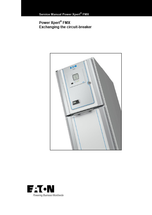
Service Manual Power Xpert® FMX Power Xpert® FMX Exchanging the circuit-breakerTable of contentsTable of contents1General 41.1Introduction 41.2Explanation of used warnings 41.3Safety relating to medium-voltage installations 41.4Tools, aids and protection equipment 51.5Product standards and guidelines used 51.6Product information 62FMX SYSTEM DESCRIPTION 82.1FMX System description 82.2Cross-section, single line diagram and list of functions 82.3Technical specifications, general 103EXCHANGING THE CIRCUIT-BREAKER 11 Appendix 1 – Contact values 21 Appendix 2 - Materials and tools 22Power Xpert® FMX 606.3768-02 8 April 2013 3General4 Power Xpert ®FMX 606.3768-02 8 April 2013 1General1.1IntroductionThe user must have authority to perform switchingoperations, which means being qualified in accordance with locally applicable guidelines, government legislation and in-house company regulations with respect to the operation of medium-voltage installations.Legal and other regulations and documents pertaining to accident prevention, personal safety and environmental protection must be observed."The service activities described in this Service Manual are the full responsibility of the user and/or the third party who perform these activities.Eaton assumes no responsibility with respect to these activities and shall not be liable for any costs, damages or losses whatsoever arising from or attributable to the service activities or to the use of this Service Manual by user and/or third party, including but not limited to loss of production, loss of profit or revenue, loss of use, claims of customers of user or for any other indirect or consequential damage or loss."Operations involving the repair of the switchgear unit are to be carried out by personnel of Eaton Industries (Netherlands) B.V. or by Eaton trained and certified personnel.Information with respect to these operations is, therefore, not included in this manual.1.2 Explanation of used warningsThe manual uses the following names and signs to highlight important (safety) information:This warning indicates that non-observance of the specified (safety) instructions COULD result in serious bodily injury or even death.NOTEThis note provides the user with additionalinformation. The user's attention is drawn to possible problems.TIPTips provide the user with suggestions and advice on how to make certain tasks easier or more convenient.1.3Safety relating to medium-voltage installationsOperations on medium-voltage installations can be life threatening if the necessary procedures are not observed.Always take suitable precautions before working on a medium-voltage installation..All personnel involved in operations carried out on, with or near electrical installations require to have been instructed on the safety requirements, safety rules and instructions applicable to the operation of the installation. Personnel must wear suitable clothing which fits the body closely. The person in charge of the operations must ensure that all requirements, regulations and instructions are complied with. The FMX unit has been designed to ensure that it exceeds applicable regulations.Furthermore, primary component enclosures are arc-resistant and interlocks have been fitted to prevent dangerous operations.Operations when the unit has been isolatedSwitching off prior to carrying out operations on an isolated system is subject to a number of essential requirements. 1. Switching off;2. Complete isolation;3. Protection from reactivation;4. Checking whether the unit is dead;5. Provide short-circuit proof protective earthing and avisible work-in-progress earth when needed.6. Provide protection with respect to active componentsin the vicinity. Safe layout of the work areaEnsure that access and escape routes are free at all times.Do not leave flammable materials in or near access and escape routes. Flammable materials must not be stored in areas which could be affected by arcs. In the event of a fireNever attempt to extinguish a fire on the switchgear unit before it is completely dead, this applies to both primary and secondary switchgear. Even if non-conducting extinguishing materials are used, electricity may pass through the extinguishing equipment. Never extinguish a fire on the unit with water. Prevent water from flowing into the unit. Keep well clear of the unit while the fire is being extinguished in the area around the unit.GeneralPower Xpert ®FMX 606.3768-02 8 April 2013 51.4Tools, aids and protection equipmentTools, aids and protection equipment must meet the requirements of national and international standards insofar as they are applicable. Drawings and documentsRecent documents of the electrical installation must be available in order to gain sufficient understanding of the schematic layout of the switchgear unit. Warning signsIf necessary, suitable warning signs shall be placed on the switchgear unit during operations to highlight possible hazards. The warning signs must comply with the applicable standards, insofar as they apply. Performing measurements safely on the unitSuitable and safe measuring equipment must be used for measuring safely on the unit. These instruments must be checked before and after use. The instruments must also be inspected periodically in accordance with the applicable regulations.1.5 Product standards and guidelines usedTable 1: Current product standards usedSwitchgear IEC Standard TitleGeneral62271-1 Common specifications for high-voltage switchgear and controlgear62271-200A.C. metal-enclosed switchgear and controlgear for rated voltages above 1 kV and up to and including 52 kV62271-201A.C. insulation-enclosed switchgear and controlgear for rated voltages above 1 kV and up to and including 38 kVDevices 62271-100 High-voltage alternating-current circuit-breakers62271-102Alternating current disconnectors and earthing switches50181Plug-in type bushings above 1kV up to 36kV and from 250A to 1.25kA for equipment other than liquid filled transformersDegrees of protection 60529 Degrees of protection provided by enclosures (IP Code)Voltage detection 61243-5 Live working - Voltage detectors - Part 5: Voltage detecting systems (VDS) Transformers 60044-1 Instrument transformers - Part 1: Current transformers60044-2 Instrument transformers - Part 2 : Inductive voltage transformers Communication 60870-5 Telecontrol equipment and systems. Part 5: Transmission protocols 61850Communications networks and systems in substations ISO ISO 9001-2000 QualityISO 14001 Environmental managementGeneral6 Power Xpert ®FMX 606.3768-02 8 April 2013 1.6Product informationThe unit is equipped with type plates on the inside walls of the secondary compartment The system nameplate includes: ∙ technical specifications;∙ serial number and year of manufacture.Each panel is uniquely identifiable by its panel nameplates.They are located on the left inside wall in the cable connection compartment of each panel. The panel type plate includes: ∙ the switch type;∙ technical specifications.Application outside the 'Normal Service Conditions' set out in IECPlease contact Eaton if the unit is used in anenvironment not in accordance with the 'Normal Service Conditions' in IEC 62271-1.Powering Business worldwideFig. 1-1: Example of system nameplateFig. 1-2: Example of panel type plate for circuit-breakerFig. 1-3: Current transformer information plateFig. 1-4: Voltage transformer Information plateGeneralTable 2: Explanation of type plate data in accordance with IECPower Xpert® FMX 606.3768-02 8 April 2013 7FMX SYSTEM DESCRIPTION8 Power Xpert ®FMX 606.3768-02 8 April 2013 2FMX SYSTEM DESCRIPTION2.1FMX System descriptionThe FMX switchgear system is a system with circuit-breakers which can be available for applications up to 24kV.The system is fully metal-enclosed. A very compact and safe implementation is achieved using high-quality epoxy resin insulation.Electric field strengths are kept at low levels by using specially shaped single-pole insulation components, as a result of which the risk of an internal fault is kept to an absolute minimum.All live primary components of the unit and the main components of the drive mechanisms are housed in a closed enclosure. This prevents any dust, moisture and other environmental factors from affecting the proper operation of the system.The enclosure is also arc resistant and thus provides conditions of optimum safety for the operator. The cable compartments are also available in arc-proof configuration.Two basic panel versions are available:∙ a vacuum circuit-breaker of 630, 800, 1250, 1600,2000 A.∙ a sectionaliser panel with vacuum circuit-breakers of1250, 1600, 2000 A.Both versions can be supplied in any combination and sequence in a system.The system has two compartments: one mainBusbar/Change-over switch compartment and a Circuit-breaker/Cable connection compartment.The main busbar system is on top of the panel and is completely closed. In the cable compartment are the current transformers and in the cable compartment voltage transformers can also be installed.The voltage transformers in the cable compartment are fully electrically operated from the front of the panel where the cable must be tested.Busbar voltage transformers are on the top of the system and also on top of the sectionalisers.Cables with a diameter up to 800 mm2 can be connected with T-connectors and cables for more than 1200 mm2, a flag connection is available.An interlocked cable connection point to test the cables is in the front of the panel.Earthing of the busbar is possible with the sectionaliser. It is also possible to make a circuit-breaker applicable for earthing the busbar. The circuit-breaker is equipped with vacuum interrupters and an electromagnetic mechanism, suitable for 30,000 operations.The circuit-breaker can be exchanged within 30 minutes from the front side of the panel.The change-over switch has two positions, connected to the busbar or connected to earth.The cable is earthed via the circuit-breaker.The interlock between the circuit-breaker and the door of the cable compartment is mechanical. The interlock between the circuit-breaker and the change-over switch is electric.The insulation of the busbar system is based on airinsulation. All other insulation is obtained by an insulating epoxy resin in which all single phase components are embedded and where the field strength between the conductors is controlled by the thickness and shape of the epoxy resin.2.2Cross-section, single line diagram and list of functionsFunctions circuit-breaker ∙ Connect cable to busbar. ∙ Disconnect cable.∙ Connect cable to earth.∙ Protect outgoing feeder from overcurrents. ∙Testing of the cable.Functions sectionaliser ∙ Connection of sections. ∙ Disconnection of sections. ∙ Earthing of sections.FMX SYSTEM DESCRIPTIONPower Xpert ®FMX 606.3768-02 8 April 2013 91. Busbar2. Secondary compartment3. Arc absorber4. Operating panel5. 2-position change-over switch6. EM-Mechanism7. Vacuum interrupter8. Cable test opening9. Cable connection 10. Voltage transformerFig. 2-1: Cross section circuit-breaker 630 / 800 A1. Busbar2. Secondary compartment3. Arc absorber4. Operating panel5. 2-position change-over switch6. EM-Mechanism7. Vacuum interrupter8. Cable test opening9. Cable connectionFig. 2-2: Cross section circuit-breaker 1250 / 1600 / 2000 A1. Busbar2. Secondary compartment3. Arc absorber4. Operating panel5. 2-position change-over switch6. EM-Mechanism7. Vacuum interrupterFig. 2-3:Cross section sectionaliser 1600 / 2000 AFMX SYSTEMDESCRIPTION2.3 Technical specifications, generalTable 3: Technical specifications* Per section one arc absorber box of 150 mm should be installed. With busbar voltage transformers the height is 500 mm more.10 Power Xpert® FMX 606.3768-02 8 April 2013 3 EXCHANGING THECIRCUIT-BREAKER Exchanging a vacuum circuit-breaker within the FMX switchgear may only be done by certified persons. Certified persons will only receive a certificate if they pass a special Eaton training. The certificate is valid for one year and only applicable for the trained person and organisation. Extension of the certificate can only be given by Eaton.Exchanging a circuit-breaker is only necessary in a very few occasions. Please consult the Eaton Service Organisation.Cables connected to the panel that needs an exchange of the circuit-breaker should be earthed on the opposite side!In case of a defect the circuit-breaker has to be exchanged and the complete system should be de-energized for a short period.Starting position of the Circuit-breaker see Fig. 3-1:∙Circuit-breaker ON.∙2-position change-over switch in Busbar position.Procedure:∙Switch OFF the circuit-breaker.∙Use the built-in voltage detector to check that the cable is dead in the outgoing panel.Arrows and dots are visible:∙Detector is functioning correctly and the cable is live.∙Arrows and dots not visible: cable is dead.NOTEThe visible dot shows that the detector is functioning correctly in accordance with the demands for voltage detecting systems as described in VDE 0682art. 415.This is a continuous internal function check.∙When the arrows and dots are not visible then check the operation of the voltage detection using thevoltage detection tester see Fig. 3-2:∙Insert the tester plugs in the contact sockets “earth” and L1. Test the detector by pressingthe tester button. The tested phase arrow anddot should now be present;∙Repeat the test for L2 and L3.∙If one or more arrows and dots do not appear, this might be the result of a faulty voltagedetector. Should this be the case contactEaton. Ensure by other means that the cable isdead before carrying out any further switchingoperations. Fig. 3-1 Fig. 3-2Fig. 3-3Power Xpert® FMX 606.3768-02 8 April 2013 1112 Power Xpert ®FMX 606.3768-02 8 April 2013 When the arrows and dots are visible then thefunctionality of the voltage detector can be tested as follows:∙ Connect a wire from the tester between thecontact sockets “earth” and L1. The arrow and dot indication from this phase must disappear. ∙ Repeat this test with the phases L2 and L3.NOTE The detector also has a piezo test button on the front for testing the LCD screen only.If the VDS system is functioning well but shows a “life” cable, switch off all incoming cables and earth these cables higher in the system.∙ Push OFF button for moving the 2-position change-over switch to the Earth position (Fig. 3-4).∙ Push ON button for Circuit-breaker ON. The cable isnow connected to earth.Fig. 3-4∙Open the top-unit and turn off the auxiliary voltage by switching the MCB's off (Fig. 3-5).Fig. 3-5∙Remove the strip, filoform covering plate and disconnect the low voltage terminals on clamps 1 up to 68 (X1) (Fig. 3-6).Fig. 3-6Power Xpert ®FMX 606.3768-02 8 April 2013 13∙Pull the Earth Lock and remove the cable door.Fig. 3-7∙Manually switch off the circuit-breaker.Fig. 3-8∙M ove the change-over selector switch to the left (Manual) position.Fig. 3-9∙Remove the 4 screws of the manual operation panel. Remove the Earth Lock and Manual Switch Off Handle.Fig. 3-10∙Push the Earth Lock support to the right.Fig. 3-1114 Power Xpert ®FMX 606.3768-02 8 April 2013 ∙Prove that all connection points (cable and change-over switch side) are dead. Do this by inserting a HV test probe into the holes and test the voltage to earth.Fig. 3-12∙ Remove the interlock of the cable compartment door (Fig. 3-13).∙Unscrew 5 captive bolts of the circuit-breaker. Leave the upper mid bolt connected. Forunscrewing the upper 2 bolts, turn the cover to open the openings (Fig. 3-14& Fig. 3-15).Fig. 3-13Fig. 3-14Fig. 3-15∙Place the truck. Make sure that the truck is placed in the right position (height) and that the brakes are activated (Fig. 3-16).Fig. 3-16Power Xpert ®FMX 606.3768-02 8 April 2013 15∙Unscrew the bolt on the backside of the Circuit-breaker (Fig. 3-17).Fig. 3-17∙Unscrew the last captive bolt (upper mid position) of the circuit-breaker (Fig. 3-18).Fig. 3-18∙Withdraw the circuit-breaker out of the panel.During withdraw make sure it is kept in a horizontal position. (Fig. 3-19)Fig. 3-19∙Remove the truck with circuit-breaker and change it by a second truck with a new circuit-breaker (Fig. 3-20).∙Place the second truck with the new circuit-breaker. Make sure it is placed in the right position (height) and that the brakes are activated (Fig. 3-21). ∙Then move the circuit-breaker into the panel.Fig. 3-20Fig. 3-2116 Power Xpert ®FMX 606.3768-02 8 April 2013 ∙Tighten the first bolt (upper mid position) before removing the truck! Tighten with a torque of 40 Nm (Fig. 3-22).Fig. 3-22∙Release the brake of the empty second truck and remove the truck (Fig. 3-23).Fig. 3-23∙Tighten the remaining 5 captive bolts. Tighten with 40 Nm. Check if the gray back plate of the mechanism hits the white plate of the housing (Fig. 3-24).Fig. 3-24∙Bring the secondary wiring with plugs back to the top-unit (Fig. 3-25).Fig. 3-25∙Tighten the bolt on the back side of the Circuit-breaker with a long tool (Fig. 3-26).Fig. 3-26Power Xpert ®FMX 606.3768-02 8 April 2013 17∙ Install the interlock of the cable compartment door (Fig. 3-27).∙Install the complete Manual Operation Panel. Make sure that the Change-over selector slide is in the manual position (left) (Fig. 3-28).Fig. 3-27Fig. 3-28∙Install the 4 screws of the manual operation panel. Install the Earth Lock and Manual Switch Off Handle (Fig. 3-29& Fig. 3-30).Fig. 3-29Fig. 3-30∙Lock the 2-position change-over switch by padlocking the selector in the mid position (Fig. 3-31).Fig. 3-31∙Turn on the auxiliary voltage by switching the MCB’s. Next close the top-unit door (Fig. 3-32).∙Switch on the circuit-breaker by pushing the push button on the top-unit door. The cable is nowearthed via the circuit-breaker (Fig. 3-33).∙Insert the test pins in the cable test facility holes (Fig. 3-34).∙Connect the test apparatus (Fig. 3-35):∙Connect the current injection cables to the earth bar and the backside of the test pin.∙Connect the voltage measurement cables to the earth bar and the backside of the test pin. ∙Switch off the circuit-breaker by pushing the push button on the top-unit door (Fig. 3-36). Fig. 3-32 Fig. 3-33 Fig. 3-34 Fig. 3-35 Fig. 3-3618 Power Xpert® FMX 606.3768-02 8 April 2013 ∙Inject 100A DC (I0) through the created circuit and measure the voltage U2 (mV) (Fig. 3-37).∙Calculate the resistance of the created circuit with following formula R2 = (U2/ I0) * 1000 (Fig. 3-38).∙Switch on the circuit-breaker by pushing the push button on the top-unit door (Fig. 3-39).∙Inject again 100A DC (I0) through the created circuits (in this case two circuits) and measure the voltage U2 (mV) (Fig. 3-40).∙Now calculate the current I2 (ADC) that runs through the cable plug with following formula:I2 = (U2 / R2) * 1000.∙Also calculate the current (I1) that runs through the circuit-breaker. This current can be calculated with following formula: I1 = I0 - I2(Fig. 3-41). Fig. 3-37 Fig. 3-38 Fig. 3-39 Fig. 3-40 Fig. 3-41Power Xpert® FMX 606.3768-02 8 April 2013 19∙Connect the voltage measurement cable to the earth bar of the 2-position change-over switch (Fig. 3-42).∙Inject again 100A DC (I0) through the created circuits (in this case two circuits) and measure thevoltage U1 (mV) (Fig. 3-43).∙Now calculate the resistance R1 of this circuit. This can be done with following formula:R1 = (U1 / I1) * 1000.∙Check if the calculated value is according the required value (see appendix for values per circuit-breaker type) (Fig. 3-44).∙If the values are ok, the breaker is built in correctly.∙Remove the test apparatus (Fig. 3-45).∙Install the filoform covering plate and strip.∙Remove the padlock on the 2-position selector switch.∙Remove the take-over earthing on the backside of the plugs.∙Install the cable door∙The panel is now ready for use again (Fig. 3-46). Fig. 3-42 Fig. 3-43 Fig. 3-44 Fig. 3-45 Fig. 3-4620 Power Xpert® FMX 606.3768-02 8 April 2013 Appendix 1 – Contact values630 A max. 160 mV 630 A max. 90 mV800 A max. 160 mV 800 A max. 90 mV1250 A * 1250 A *1600 A * 1600 A *2000 A * 2000 A ** Please contact Eaton for more information.Power Xpert® FMX 606.3768-02 8 April 2013 2122 Power Xpert ®FMX 606.3768-02 8 April 2013 Appendix 2 - Materials and toolsMaterials:∙ Scotch-Brite pads ∙ Silicon grease ∙ Acid free Vaseline ∙ BreakerTools:∙ Special long tool (green piece)∙Truck for replacing breaker∙Voltage test pinPower Xpert® FMX 606.3768-02 8 April 2013 23Eaton’s Electrical Sector is a global leader in power distribution, power quality, control and automation, and monitoring products. When combined with Eaton’s full-scale engineering services, these products provide customer-driven PowerChain™ solutions to serve the power system needs of the data center, industrial, institutional, public sector, utility, commercial, residential, IT, mission critical, alternative energy and OEM markets worldwide.PowerChain solutions help enterprisesachieve sustainable and competitiveadvantages through proactivemanagement of the power system as astrategic, integrated asset throughoutits life cycle, resulting in enhancedsafety, greater reliability and energyefficiency. For more information, visit/electrical.Eaton Industries (The Netherlands) B.V.P.O. Box 237550 AA HengeloThe NetherlandsTel.: +31 74 246 91 11Fax: +31 74 246 44 44***********************www.eaton.eu/electrical© 2013 Eaton CorporationAll rights reservedArt.no.: 606.3768-02。
伊顿公司全液压转向器应用培训资料重点
组合阀块中安全阀压 力低.
7.回油滤油器被堵塞.
8.泵严重磨损或损坏,容积效率低.产生的压力和流量 不能满足系统 要求 .
59
问题 2 – 蛇行
车辆不走直线.
60
40
开芯无反应转向系统原理图(带组合阀)
双向补油阀 双向缓冲阀
人力转向单向阀 安全阀
入口单向阀
41
负荷传感转向系统
负荷传感全液压转向系统
该系统具有如下优点(比较开芯系统) • 对转向负载的变化有良好的压力补偿 • 转向回路与其他工作回路互不影响,主 流量优先保证转向回路,转向器在中位 时只有很少流量通过转向器,系统节能 • 转向回路压力流量保持优先,转向可靠 • 中位压力特性不受排量的影响 •可以实现流量放大等功能
17
全液压转向原理
全液压转向器控制 (SCU)
18
全液压转向原理
19
全液压转向原理
20
全液压转向原理
21
全液压转向原理
22
全液压转向原理
23
全液压转向原理
24
全液压转向原理
25
全液压转向原理
26
全液压转向原理
27
全液压转向原理
28
全液压转向原理
29
全液压转向原理
30
全液压转向原理
结构切面立体示意图:
47
转向器配套组合阀块
48
FK/FKS阀块功能原理图
入口安全阀 入口单向阀 双向过载阀 双向补油阀
49
转向器配套组合阀块的产品功能简介
组合阀功能: 1. 安全阀---压力油到达安全阀设定压力时,安全阀打开泄油,提
供转向系统压力的安全保护。 2.双向过载阀---当转向油缸受到外部冲击时,油缸内的压力升高,压 力油到达过载阀设定压力时,过载阀打开泄油,对转向油缸实施过载保 护。 3.双向补油阀---当过载阀开启时,为防止油液产生气蚀,补油阀打开从组 合阀块的回油口吸油,及时将压力油补充到转向油缸的左或 右油腔。 4.入口单向阀---转向器进油时单向阀打开。在低转速时防止由于外部 载荷的冲击,高压油倒流,造成方向盘的抖动。油流方向 变化,单向 阀截止。
伊顿 Crouse-Hinds 系列 MTL SD 安全手册 说明书

FSM FUNCTIONAL SAFETY MANAGEMENTThese products are able to be used within a Safety System conforming to the requirements ofIEC 61508:2010 or IEC 61511. The products are not Safety Elements but may be used toprotect instrument loops designed to achieve Safety Integrity Level of up to SIL3.Eaton is a certified Functional Safety Management company meeting the requirements of IEC61508 Part1:clause 62SM MTLSurge rev 3This manual supports the application of the products in functional safety related loops. It must beused in conjunction with other supporting documents to achieve correct installation, commissioningand operation. Specifically, the data sheet, instruction manual and applicable certificates for theparticular product should be consulted, all of which are available on the Eaton web site.In the interest of further technical developments, Eaton reserve the right to make design changes.Contents1 Introduction31.1 Applicationandfunction 31.2 Variantdescription 32 System configuration42.1.1 Input/outputcharacteristics 52.1.2 Associated system components 53 Selection of product and implications 64 Assessment for use inFunctional Safety applications 64.1 EMC 84.2 Environmental85 Installation87 M aintenance88 Appendices9 Machine Monitor Interfaces1 Introduction1.1 Application and functionThe products concerned in this manual are ‘Surge Protection’ devices which can be located in safe or hazardousareas of a process plant to guard against the direct and indirect effects of lightning, or other transient overvoltage,on the instrumentation and power signals. They are also designed and tested according to IEC 61643-21 (Lowvoltage surge protective devices) for use in signal and communication loops.The location, or mounting, of the surge protection device is a key parameter when considering the operationof the device and the consequences of breakdown or failure upon the operation of the signal loop to which itis connected.The TP family of products are designed to protect field-mounted equipment, such as process measurement transmitters for level, flow, pressure, etc, by fixing directly into the cabling conduit entries of the housing. TheSD, SLP and IOP range are mounted on DIN rail in a cabinet or enclosure to protect the measuring and controlequipment that is usually located in a control or equipment room.Each module provides a hybrid surge protection circuit for one or two instrument loops. The devices are passiveand consume no loop current in normal operation.There are no configuration switches or operator controls to be set on the modules – they perform a fixed function,related to the model selected, and can be considered as wiring components that pass the process signals withoutalteration.Surge protectors rangeNote: The information given in this manual is intended to assist in the selection and application of surgeprotection devices for instrumentation signals that are being used to provide functional safety according to thelatest IEC 61508 and IEC 61511 standards.Within the context of these standards the surge protection devices themselves do not perform a defined safetyfunction and thus a full assessment for functional safety to IEC 61508 would not be relevant. The products areregarded as wiring components, providing connection and termination for the electrical signals, with the keyconcern being the reliability of the signal transfer through the device.See Appendix B where this position is affirmed by a notified certification body.1.2 Variant DescriptionFunctionally the surge protection devices are essentially the same, within a given range, but the modules differin the maximum signal voltage they will conduct in normal operation.The TP items become an integral part of the field transmitter and the SD/SLP/IOP models are selected to suit thespecific requirements for protection of one or more process loops.SM MTLSurge rev 334SM MTLSurge rev 3Typical internal construction of the devices is shown in the following diagrams:Figure 1 IOP range surge protection arrangementFigure 2 IOP range surge protection arrangement, (single channel)(dual channel)Figure 3 SD range surge protection arrangementFigure 4 TP range surge protection arrangement (typical), except SD150X/275X(Parallel)Figure 5 SD150X/SD275X surge protection arrangement% & 4565SM MTLSurge rev 3System ConfigurationThe surge protection devices may be used as protective wiring components in functional safety applications but the devices are not considered as ‘safety elements’ conforming to the requirements of IEC 61508. As stated previously, the protection devices limit the energy seen by instrument systems as a consequence of external electrical events such as induced surges, voltage transients, etc arising from lightning strikes or high voltage switching for example. Users of these surge protection devices can utilize the failure rate information contained in this manual in a probabilistic model of a Safety Instrumented Function (SIF) to determine suitability of the safety instrumented system to achieve the required Safety Integrity Level (SIL).The figure below shows an example system configuration and specifies detailed interfaces to the safety related system components. It does not aim to show all details of the internal module structure, but is intended to support understanding for the application.The SD/SLP/IOP modules are designed to protect the input into the safety plc from damaging transients and surge. The yellow (hatched) area shows the safety relevant system connection.Consideration must be given to the use of dual channel devices when considering the integrity of the installation. A failure in one channel of a two channel device will require replacement of the complete module and the downtime of the two loops connected.Otherwise, functionally the single channel and dual channel units are the same.2.1.1 Input/Output CharacteristicsThe SD/SLP/IOP/TP surge protectors are passive devices and do not modify or alter the signal in normal operation, but simply limit electrical energy.2.1.2 Associated System ComponentsThe surge protectors are wiring components in the signal path between safety-related sensors or other fielddevices and safety-related instruments or control systems.3 Selection of product and implicationsThe choice of surge protection component is made according to the location, signal type, signal level andoperational or maintenance considerations for the safety instrumented function rather than any safetyaspect of the surge components themselves.See the previous comments regarding the nature of surge protection in relation to functional safety applications.The information given in section 4 provides the hardware failure rates for the surge protection devices according tothe expected consequence of the failures upon the signal passing through the device. The user can thus assess theeffect of such failures upon the safety instrumented function.4 Assessment for use in functionalsafety applicationsOn their own, surge protection devices do not perform a safety function and are considered as wiringcomponents within the contexts of IEC 61508 and its associated standards. As such, the evaluation for usewithin a safety function, to a specific SIL level of such products, is not possible. However, when used as part ofa complete safety system, the product can be assessed with regard to failure modes and effects on the overallsystem.The hardware assessment shows that the surge protection devices:• have a hardware fault tolerance of 0• are classified as Type A devices (“Non-complex” component with well-defined failure modes)• There are no internal diagnostic elements of these products.The results of a Failure Mode and Effect Analysis to determine the hardware failure rate of the modules weredetermined as follows:-TP Parallel surge suppression devices* signal is driven outside normal operating range of 4/20mA and is detectable by the logic solver.6SM MTLSurge rev 3SD range surge suppression devices(i) SDyy used to represent SD07, SD16, SD32 and SD55(ii) z3 used to represent R3, T3 and X3* Surge protectors type SD150X and SD275X are intended for use in circuits that pass binary signals; hence thecorruption of analogue signals is not considered.SLP range surge suppression devicesIOP range surge suppression devices• FITs means failures per 109 hours or failures per thousand million hours.• Reliability data for this analysis is taken either from the Electrical and Mechanical Component Reliability Handbook, 2006, by Exida L.L.C., or from IEC TR 62380:2004.It is assumed that the device is installed, operated and maintained according to the product specification. Theproduct has been assumed to operate at an average ambient temperature of 40°C under normal conditions. Fora higher average temperature of 60°C, or if subject to frequent temperature fluctuation, the failure rates shouldbe multiplied with an experience based factor of 2.5.The information given here is to help the designer of a Safety Instrumented Function assess the impact ofincluding surge protection devices on the operation and availability of the instrument loops.The surge devices themselves are not ‘safety elements’.SM MTLSurge rev 374.1 EM CThe surge protection devices are designed for operation in normal industrial electromagnetic environment but,to support good practice, modules should be mounted without being subjected to undue conducted or radiatedinterference, see Appendix A for applicable standards and levels.Any maintenance or other testing activity should only be conducted when the field loop is not in service, toavoid any possibility of introducing a transient change in the field signal.4.2 EnvironmentalThe surge protection devices operate over the temperature range from -40°C to +70°C, and at up to 95% non-condensing relative humidity.The devices are intended to be mounted in a normal industrial environment without excessive vibration, asspecified for the specific product ranges. See Appendix A for applicable standards and levels.Continued reliable operation will be assured if the exposure to temperature and vibration are within thevalues given in the specification.5 InstallationThere are two particular aspects of safety that must be considered when installing the surge protection devicesand these are:• Functional safety (applicable when used in SIFs)• Intrinsic safety (only applicable when used in intrinsic safety loops)When required, reference must be made to the relevant sections within the instruction sheet or manualfor the product range which contain basic guides for the installation of the interface equipment to meet therequirements of intrinsic safety. In many countries there are specific codes of practice, together with industryguidelines, which must also be adhered to.Provided that these installation requirements are followed then there are no additional factors to meet theneeds of applying the products for functional safety use.With the exception of the TP models which are designed for field mounting, to guard against the effects of dustand water the modules should be mounted in an enclosure providing at least IP54 ingress protection rating, orthe location of mounting should provide equivalent protection such as inside an equipment cabinet.6 M aintenanceTo follow the guidelines pertaining to operation and maintenance of intrinsically safe equipment in ahazardous area, periodic audits of the installation are required by the various codes of practice.In addition, proof-testing of the instrumented loop operation to conform with functional safety requirementsshould be carried out at the intervals determined by safety case assessment.The continuity of the surge device will be tested (not surge function) when the overall loop function is testedboth during commissioning and through the life of the intended safety function. The removal of the Surgeprotective device during these tests is not required.If an Eaton MTL surge protection device is found to be faulty during commissioning or during the normallifetime of the product then such failures should be reported to Eaton. When appropriate, a CustomerIncident Report (CIR) will be notified to enable the return of the unit to the factory for analysis. If the unit iswithin the warranty period then a replacement unit will be sent.Consideration should be made of the normal lifetime for a device of this type which would be in the region oftwenty years, with a typical warranty period of ten years.8SM MTLSurge rev 37 AppendicesAppendix A: Summary of applicable standardsThe annex lists together all standards referred to in the previous sections of this document:SM MTLSurge rev 3910SM MTLSurge rev 3Appendix B:Functional Safety and Surge Protection DevicesThis page is left intentionally blankSM MTLSurge rev 311The given data is only intended as a product description and should not be regarded as a legal warranty of properties or guarantee. In the interest of further technical developments, we reserve the right to make design changes.EUROPE (EMEA): +44 (0)1582 723633 ********************THE AMERICAS: +1 800 835 7075 *********************ASIA-PACIFIC: +65 6645 9864 / 6645 9865 ***********************Eaton Electric Limited, Great Marlings, Butterfield, Luton Beds, LU2 8DL, UK.Tel: + 44 (0)1582 723633 Fax: + 44 (0)1582 422283E-mail:******************** © 2018 Eaton All Rights Reserved Publication No. SM MTLSurge rev 3 181018October 2018AUSTRALIA MTL Instruments Pty Ltd, 10 Kent Road, Mascot, New South Wales, 2020, Australia Tel: +61 1300 308 374 Fax: +61 1300 308 463E-mail:*********************BeNeLuxMTL Instruments BV Ambacht 6, 5301 KW Zaltbommel The Netherlands Tel: +31 (0) 418 570290 Fax: +31 (0) 418 541044E-mail:*********************CHINA Cooper Electric (Shanghai) Co. Ltd955 Shengli Road, Heqing Industrial Park Pudong New Area, Shanghai 201201Tel: +86 21 2899 3817 Fax: +86 21 2899 3992E-mail:****************FRANCE MTL Instruments sarl,7 rue des Rosiéristes, 69410 Champagne au Mont d’Or France Tel: +33 (0)4 37 46 16 53 Fax: +33 (0)4 37 46 17 20E-mail:*******************GERMANY MTL Instruments GmbH,Heinrich-Hertz-Str. 12, 50170 Kerpen, Germany Tel: +49 (0)22 73 98 12 - 0 Fax: +49 (0)22 73 98 12 - 2 00E-mail:*******************INDIA MTL India, No.36, Nehru Street, Off Old Mahabalipuram RoadSholinganallur, Chennai - 600 119, India Tel: +91 (0) 44 24501660 /24501857 Fax: +91 (0) 44 24501463E-mail:***********************ITALY MTL Italia srl, Via San Bovio, 3, 20090 Segrate, Milano, ItalyTel: +39 02 959501 Fax: +39 02 95950759E-mail:******************JAPAN Cooper Crouse-Hinds Japan KK, MT Building 3F, 2-7-5 Shiba Daimon, Minato-ku,Tokyo, Japan 105-0012Tel: +81 (0)3 6430 3128 Fax: +81 (0)3 6430 3129E-mail:****************NORWAY Norex AS Fekjan 7c, Postboks 147, N-1378 Nesbru, Norway Tel: +47 66 77 43 80 Fax: +47 66 84 55 33E-mail:*************RUSSIA Cooper Industries Russia LLC Elektrozavodskaya Str 33Building 4Moscow 107076, RussiaTel: +7 (495) 981 3770 Fax: +7 (495) 981 3771E-mail:*******************SINGAPORE Cooper Crouse-Hinds Pte Ltd No 2 Serangoon North Avenue 5, #06-01 Fu Yu Building Singapore 554911Tel: +65 6645 9864 / 6645 9865 Fax: +65 6 645 9865E-mail:***********************SOUTH KOREA Cooper Crouse-Hinds Korea 7F. Parkland Building 237-11 Nonhyun-dong Gangnam-gu,Seoul 135-546, South Korea.Tel: +82 6380 4805 Fax: +82 6380 4839E-mail:*******************UNITED ARAB EMIRATES Cooper Industries/Eaton Corporation Office 205/206, 2nd Floor SJ Towers, off. Old Airport Road,Abu Dhabi, United Arab EmiratesTel: +971 2 44 66 840 Fax: +971 2 44 66 841E-mail:*****************UNITED KINGDOM Eaton Electric Limited, Great Marlings, Butterfield, LutonBeds LU2 8DLTel: +44 (0)1582 723633 Fax: +44 (0)1582 422283E-mail:********************AMERICAS Cooper Crouse-Hinds MTL Inc.3413 N. Sam Houston Parkway W.Suite 200, Houston TX 77086, USA Tel: +1 281-571-8065 Fax: +1 281-571-8069E-mail:*********************。
Eaton RTLO-13和RTLO-18速手动变速箱说明书

Performance Bundle ProgramThe #1 transmission ofprofessional drivers just gotbetter! New trucks spec'dwith 13- or 18-speedmanual transmission, SoloAdvantage® clutch andEaton-approved lube nowreceive a 7-year or 750,000mile warranty on thetransmission and 5-yearor 500,000 mile warrantyon the clutch.Linehaul, VocationalStep 1: Select an Eaton RTLO-13 or RTLO-18 speed manual transmissionOur rugged manual transmissions have been the industry standard for years. With the Eaton 13 and 18-speed manual transmission, drivers will experience versatility and low-shift effort in a premium Fuller transmission. The innovative, patented design features a simple mainshaft, resulting in fast easy shifts.Step 2: Select an Eaton Advantage Series Self-Adjust clutchBuilding on over a hundred years of driveline design experience and millions of miles of proven durability, the new Advantage clutches are the smoothest and most durable clutches Eaton has developed.Step 3: Fill with Eaton-approvedlubricantEaton’s PS-386 SyntheticTransmission Fluid is designedspecifically to optimizeperformance in Eatontransmissions. PS-386 improvesfuel economy, reduces frictionand gear wear, and prolongs thelife of your transmission.Step 4: Register by completingthe formY ou must register to receive thePerformance Bundle extendedwarranty. Complete form onsecond page and follow thesubmission instructions, orcomplete form online at/warranty*Applies to applications in the U.S.& Canada only. Please refer to theRoadranger Warranty Guide (TCWY0900)for the latest warranty time and mileageofferings.Notes:•Extended warranty promotionapplies regardless of application.•Excludes “Convertible” 9/13 speeds.S U P P O R TB AC K ED B YFor spec’ing or service assistance, call 1-800-826-HELP (4357) or visit /roadranger.In Mexico, call 001-800-826-4357. Roadranger: Eaton and trusted partners providing the best products and services in the industry, ensuring more time on the road.EatonVehicle Group13100 E. Michigan Ave.Galesburg, MI 49053 USA800-826-HELP (4357)/roadranger© 2017 EatonAll Rights Reserved. Printed in USA.APSL0311 0617Note: Features and specifications listed inthis document are subject to change withoutnotice and represent the maximum capa-bilities of the software and products with alloptions installed. Although every attempthas been made to ensure the accuracy ofinformation contained within, Eaton makesno representation about the completeness,correctness or accuracy and assumes noresponsibility for any errors or omissions.Features and functionality may vary dependingon selected options.Eaton, Fuller, Roadranger, Solo, UltraShift andFuller Advantage are registered trademarks ofEaton. All trademarks, logos and copyrightsare those of their respective owners.Reward yourself by spec’ing a new truck with theultimate drivetrain performance and free extendedwarranty in four easy steps:The free extendedwarranty is only availablefor a limited time.This program is for newtrucks purchased orordered with an EatonRTLO-13 or RTLO-18manual transmissionwith Eaton AdvantageSeries Self-Adjust clutchand Eaton-approved lubebetween July 1, 2016and June 30, 2018.Spec your truck today!Performance T ransmission Bundle Warranty Registration FormUse this form to activate extended warranty on:•Eaton RTLO-13 or RTLO-18 manual transmission •Eaton Advantage Series Self-Adjust clutchPerformance Bundle Warranty Instructions:1.Purchase of Eaton RTLO-13 or RTLO-18 speed manual transmission (models include RTLO-16913A, RTLO-18913A, RTLO-20913A, RTLO-16918B, RTLO-18918B, RTLO-20918B or RTLO-22918B), Eaton Advantage Series Self-Adjust clutch and Eaton-approved synthetic lubricant is required to activate extended warranty.2.Please enclose proof of purchase or repair order listing transmission and clutch along with this form to activate the warranty.3.Coverage confirmation will be sent by USPS mail.4.Convertible 9/13 speeds are not included in this program.Step 1: Enter owner/dealer informationOwner:____________________________________________________________Address:__________________________________________________________City:______________________________________________________________State/Prov:________________________ Postal Code:_____________________Phone:____________________________________________________________Email:____________________________________________________________Step 2: Enter vehicle/component informationOEM __________________________________ Date-In-Service ________________________Chassis VIN (17 characters): _______________________________________________________________________________________________________________T ransmission Model: ___________________________________________________ T ransmission Serial: ________________________________________________Clutch Part No.: ______________________________________________________ _Vehicle vocation (choose one only -– all applications qualify for this extended warranty promotion)Standard DutyRecreation Vehicleransit CoachSevere DutyHeavy Haulard TractorStep 3: Mail, fax or email this completed form with proof of purchase to:Mail: EatonFax:Email:c/o 360 Services, Inc.1-734-591-7899******************************275 E. 12 Mile Rd.Madison Heights, MI 48071Dealer Code:______________________________________________________Dealer:____________________________________________________________Dealer Contact:_____________________________________________________Dealer Contact Email:______________________________________________Address:__________________________________________________________City:______________________________________________________________State/Prov:________________________ Postal Code:_____________________Phone:____________________________________________________________S U P P O R T B A C K E D B Y© 2017 EatonCheck here for email confirmation of warranty submission (please ensure you enter your email address above).。
伊顿变速箱驾驶员培训指导

钥匙到START位置,发动机会很快启动。发动机 启动后,松开钥匙,钥匙自动返回到ON位置。 4. 按换档按钮的 “R”(倒档) 或“D” (前进档)或者“M”( 手动换档模式)或 “L”(低速档) 。 5. 当选择了D/M时,可以通过升档/降档按钮选择起 步档位,但起步档位不会高于二档。 6. 松开手刹,然后缓慢松开刹车踏板,即可行车。
警告: 在确认变速箱在空挡位置且踩住刹车踏板后,再启动发动机。 否则,汽车的突然移动可能会导致事故甚至人员伤亡。
起步和停车
停车
1. 车辆停稳后,通过换档按钮使变速箱处于空档位置。 2. 向后拉手刹使之起作用,此时发动机将自动关闭。 3. 逆时针转动钥匙至OFF位置并取出钥匙。 自动变速箱自检和关闭还需要20秒。在
BJ6123HEV 驾驶员培训指导
2002 Eaton Corporation. All rights reserved.
BJ6123HEV整车介绍
离合器
驾驶员座位
车前部
变速箱
发动机
危险: 高压部件区域
Carrier 逆变器
电池盒
高压线
车后部
电机 Motor
换档按钮和仪表介绍
换档按钮
R N D 倒档 选择倒档时,车辆必须停稳 空挡 前进档,采用最佳的自动换档模式 Low 低速档,当坡度大于10%(上坡或下坡)时 选用。此种模式下会调整换档点以实现最佳的 爬坡性能和发动机制动性能 MANUAL 手动换档模式,可以让驾驶员保持当前 档位或使用升档/降档按钮选择合适的档位。驾 驶员可以在任何时候选择这种模式,比如起步 ,过铁轨,爬大坡等 升档/降档 按钮 在手动模式时使用,可以实现升档或降档。 在D/M时,也可以使用升档/降档按钮选择起步 档位(一档或二档)。 注: 变速箱会自动升档或降档以防止发动机转 速过高或者熄火。 故障指示灯 提醒驾驶员混合动力系统发生了故障。
伊顿 NRX 系列 Kirk Key 联锁装置操作说明书

NRX 系列Kirk Key 联锁装置的操作说明NRX 系列NF 类型壳架ANSI, UL1066, UL489 / IEC, IZMX16, IZM91NRX 系列RF 类型壳架IEC, IZMX40本手册适用于:警告(1) 只有具备电气资格的人员才能操作此设备。
(2) 如断路器不能被搬移至安全的工作地点,则务必始终断开一次和二次回路电源。
(3) 抽出式断路器需摇至断开位置。
(4) 所有断路器均需处于分闸状态,机械弹簧需释能。
若违反此说明手册中的这些程序,会导致人员伤亡或财产损失。
ƽ 警告应遵守本操作说明书及产品标签上规定的操作说明。
请注意以下五点安全规则:– 断电;– 确保装置不能意外重启;– 确保与电源隔离;– 接地及短路;和– 遮盖或为临近带电部件提供屏障断开设备电源。
在设备维修期间,仅可使用正规渠道获得的备件。
在维修和更换时,必须严格遵守规定的维修间隔及说明,以避免人身伤害及开关板损坏。
20211220116操作说明书2021年12月版NRX 系列Kirk Key 联锁装置的操作说明2伊顿公司 /electrical第1部分:基本信息钥匙联锁装置可将断路器固定在“OFF ”位置。
该装置安装在断路器的上部,并可通过前盖看到,钥匙锁由客户提供。
该装置具有以下安全功能:1. 没有钥匙时,断路器处于“断开”状态,不可合闸。
2. 钥匙在“ON ”位置(钥匙在锁芯内)且转动时,断路器可提供全部功能。
3. 断路器在“ON ”(闭合)状态时,钥匙不可拔出。
注:如要取下钥匙,首先按下断路器“OFF ”按钮,然后将钥匙逆时针旋转90度。
装置部件标识请参阅图1来直观识别下列部件:(A) 外保护环 (自粘式) (1个)(B) Kirk Keylock #KC40.10 (不提供Kirk Keylock) (C) 支撑垫圈 (1)个)(D) 金属安装支架 (1个) (E) 纤维保护垫圈 (2个)(F) M3 x 5mm 安装螺丝 (2个)(G) 大锁紧螺母 (1个) (不是装置的一部分,随钥匙锁提供)注:Kirk Keys 可能会一个Kirk Key 配两个大锁紧螺母。
伊顿变速箱驾驶员操作手册
更多信息请到RoadRanger网站查询:警告标识本手册中的有些段落会有DANGER,WARNING,或者CAUTION的标识。
这些段落包含特殊的安全信息,进行操作之前必须通读理解这些信息,并在操作过程中留意。
DANGER:该标识表明如果不遵守规定的操作程序,会有人员严重受伤或死亡的可能。
WARNING:该标识表明有直接的危险存在,如果不遵守规定的操作程序,会有人员严重受伤的可能。
CAUTION:该标识表明如果不遵守规定的操作程序,会导致车辆损坏或财产损失。
注意:在操作过程中注意细节有助于故障诊断或系统维修。
操作变速器前通读本手册车辆启动前驾驶员要坐在驾驶员座椅上,按空档(N),拉起手刹如果启动发动机时变速器没有在空档位(N),立刻检查车辆你在操作车辆过程中如果要停车或暂时下车,一定要按空档(N),拉起手刹,并在车轮处加塞块出于安全的原因,变速器挂档前请踩住刹车踏板进行任何焊接操作前,24V电池的正极和负极必须完全断开高压警告标识使用二氧化碳或者干粉灭火器,电池盒中的电池为锂离子电池高压线束为橙红色,并在接头位置有警告标签所有Eaton的柴油混合动力车辆在车内都有高压元件位置图不要切断或移动橙红色高压线束,参见高压元件位置图不要切割或打开电池盒,参见高压元件位置图不要切割或打开逆变器,参见高压元件位置图本手册中的紧急关机程序会说明如何在紧急情况时关闭电源警告标识 (i)紧急关机程序 (1)发生火灾时的紧急程序 (2)发生交通事故时的紧急程序 (2)高压元件特征 (3)换档按钮说明 (4)启动和停车 (5)倒档 (6)前进档-自动换档模式 (6)前进档-手动换档模式 (6)低速档 (7)再生制动模式 (7)一般型号信息 (8)故障排除 (9)档位卡死 (9)正确润滑 (10)正确的油面高度: (11)混合动力冷却系统 (11)紧急关机程序方法1:关钥匙(推荐)发动机会关闭仪表盘会关闭混合动力系统会关闭混合动力电池只在电池盒中有电方法2:断开24V电池发动机会关闭仪表盘会关闭方法3:拔掉混合动力控制器的保险丝(30A)混合动力系统会关闭混合动力电池只在电池盒中有电这些程序只适用于紧急情况,车辆维修时请参见《维修手册》中的相关内容发生火灾时的紧急程序如果车辆发生火灾:1.使用二氧化碳或者干粉灭火器,电池盒中的电池为锂离子电池高压线束为橙红色,并在接头位置有警告标签所有Eaton的柴油混合动力车辆在车内都有高压元件位置图不要切断或移动橙红色高压线束,参见高压元件位置图不要切割或打开电池盒,参见高压元件位置图不要切割或打开逆变器,参见高压元件位置图发生交通事故时的紧急程序如果条件允许,请把车推到路肩上并停车1.拉手刹2.按空档(N)3.关钥匙4.如果安全的话,下车高压线束为橙红色,并在接头位置有警告标签所有Eaton的柴油混合动力车辆在车内都有高压元件位置图不要切断或移动橙红色高压线束,参见高压元件位置图不要切割或打开电池盒,参见高压元件位置图不要切割或打开逆变器,参见高压元件位置图高压元件特征所有的高压线束为橙红色,并在接头位置有警告标签;每一个高压元件都有明显的警告或危险标识。
伊顿(Eaton)CW-HMX高层建筑多功能声学应急疏散系统操作手册说明书

CW- HMXHigh rise multiplex systemCW-MX-MPMaster panelCW- HMX-DPDistribution panel2Operations manualCW- HMX 25-16567-A August 2019 CW-HMX product overviewThe CW-HMX high rise evacuation system operates in conjunction with the fire alarm control panel (FACP) in a building to provide automatic audio response to life safety emergencies.The CW-HMX includes all necessary features to provide an effective voice evacuation system. The cooperwheelock CW-HMX can be custom configured to satisfy the needs of any high rise application.Fire department authorities can easily take command of evacuation or relocation procedures and emergencies. Building management and fire brigades can monitor and control emergency response even before the professionals arrive.The CW-HMX system includes capacity for 6 channels of simultaneous audio. This provides for evacuation,stay-in-place, or other public address announcements and automatic messages.Optional featuresOptional features may include Fire fighter phones or Warden stations as required by local code. Area-of-rescue stations can reassure handicapped occupants that help is on the way. Smoke control, stair pressurization, and HVAC shutdown can be completely automatic, unless controlled manually by management or fire authorities.Product overview CW-HMX Distributed panel3CW- HMX 25-16567-A August 2019 CW-HMX product overviewMaster panelcontrols and displays4CW- HMX 25-16567-A August 2019 System functionsThe control panel status indicators are “Alarm”, “Fault”and “Power”.During “Power on diagnostics”, the system is scanned for active distributed panels and peripherals. The message display indicates how many distributed panels have been found and all event buffers are cleared.•The green “Power” indicator is on as long as there is power available to the CW-HMX master panel.•The red ‘‘Alarm” indicator will be on whenever an alarm condition exists.•The yellow ‘‘Fault” indicator will be on (blinking) whenever a fault has occurred in the CW-HMX system.While the fault is active an audible indicator will sound and the message display will indicate a code for the fault that has occurred. A list of these fault codes is on page #9. These fault conditions are not serviceable by theuser - please contact your installer. In addition, the audible fault signal will be active (beep tone) as long as thefault persists. The “Fault Silence” switch can be used to silence the audible fault indication, but the visual indicator can only be cleared by an CW-HMX system reset, a single click will clear the flashing LED if the fault condition no longer exists. The FACP will also indicate a fault as long as an active fault condition exists. It may return to normal or remain in fault depending on the fire panels own operational guidelines.The “All-Call” switch will select all available Evacuation/ Paging zones on the Paging/Zone control panel when clicked. Individual paging zones may be deselected using the Paging/Zone control switches, but a second click of the “All-Call” switch will deselect the remainder.resettestPaging / Zone control panel switch/led status All switches are three position and rest at the centerposition. They may be momentarily clicked up or down.If configured for speaker zones and manual message playback(LED solid red) Zone selected (click switch up to select, up again to deselect)(LED flashing red) Alarm condition reported(LED yellow) Fault detected - audible tone will also be presentIf configured for fire phone zones(LED flashing red) call in - a fireman’s phone is plugged in at that location. Audible ring in tone will be active until Call is acknowledged and connected.(LED solid red) connected (click switch up to connect, up again to disconnect)(LED yellow) fault detected - audible tone will alsobe present(LED solid green ) Zone selected for message playback (click switch down to select, down again to deselectIf configured for speaker zones and zone expansion is on:Zone is ready for alarm zone expansion.If System is in Alarm (click switch down to select,LED will flash red.)Function switch panel - Located on HMX master panelSystem functions5 CW- HMX 25-16567-A August 2019 6CW- HMX 25-16567-A August 2019 Fire phoneFire phone handset - When a fire phone handset is plugged into a fire phone jack, the LED on the zone control panel associated with that fire phone zone will start flashing. A ringing signal will be heard to indicate that a handset has been jacked in. The ringing signal will cease when that fire phone zone is selected (click switch up). Y ou may then communicate with the emergency worker by picking up the red fire phone handset.Fire phone zone - Normally, only one fire phone zone is selected at a time. Selecting another zone where ahandset is jacked in will deselect the other zone(s). Where more than one zone is to be selected at a time, party line mode must be selected.Fire phone circuit - If a fault is detected on any fire phone circuit, the LED will change to yellow and the audible fault tone will be present.Warden station call switch - Only active on systems utilizing warden stations. When a station is selected, Call Switch will initiate a call to that station. LED indicator on the station will flash or the optional alert tone will sound.Warden station Fire phone control -Located on HMX master panelTrouble codes reported on message displayUnit will flash “-F” and then the two letter code every 2.5 seconds. Multiple codes will alternate every five seconds, display in order and then resume at the beginning.DFDisplay fault - One or more of the system zones is in trouble. Associated zoneLED will be flashing yellow. This may be on any page, phone or control circuit.AC AC Power fault BF Battery failure GF Ground fault MF Microphone faultBI Bus interface fault - System communication is compromised SF Scan card fault - Switch interface is in troubleRF Remote distributed panel fault - Will be followed by a # designating which panel is in trouble.SI Secondary (Style 7) HMX Bus fault AF External audio faultTOTime out, system does not see complete data loop, no data on return lineIn the event of any fault condition,please contact your installing dealer orCooper wheelock technical assistance - (888) 382-9835reset testSystem functionsCW-HMX Fault codesCW-HMX Fault messages are displayed on the MMC. The MMC (Master Microphone Control) panel has afault status LED, a two character display for limited fault messages, an audible trouble annunciator and switches for reset (topmost switch #1) and trouble silence (third from top #3).The fault LED will flash when a fault has occurred in the system and the audible trouble annunciator will sound. The specific fault will be displayed on the MMC and, if the fault is associated with a switch, on the SLC (Switch/LED Card) as well.If the fault is cleared the fault message and the audible will reset, but the fault status LED will continue to flash until the system is reset.The fault messages are displayed one at a time and change every 2.5 seconds. A complete message is displayed every 5 seconds (or 7.5 - 10 seconds if there are numbers or codes to display) in the following sequence. Displayed Description-F Indicates the start of a fault messagecc One or two character fault codenn Optional numeric code (indicates # of remote dist panel)nn Optional numeric code if number exceeds 99Thus, if the fault were a battery failure, the sequence would be;-FBF-FBF(repeat until cleared)If this were accompanied by a microphone fault, the sequence would be;-FBF-FMF-FBF(repeat until cleared)If the fault were a failure in a remote panel(e.g. Amp failure in DP#3), the message would be;-FRF+003-FRF+003(repeat until cleared)Faults associated with a given switch, such as a speaker loop would cause the following message with the accompanying switch on the SLC flashing yellow (e.g. an open speaker loop associated with switch #6).(Switch #6 flashing yellow)-FDF-FDF(repeat until cleared)The current fault messages are as follows:Displayed Description-F Start of messageDF Display fault (Note 2)AC AC Power faultBF Battery failureGF Ground fault (Master panel)MF Microphone faultBI Bus interface faultSF Scan card faultRF Remote distributed panel fault (note 1)SI Secondary (Style 7) HMX Bus faultAF External audio faultTO Time outotee:N The first character of the numeric code displayed (left character, after the therefore code is displayed)indicates the nature of the Remote Fault. If theremote panel has stopped responding the characterwill be an asterisk (*). If the Remote Panel is tryingto indicate a fault that has no associated switch orother code, the character will be a plus sign (+).This indicates that there may be a ground fault, anamplifier module fault or other fault condition inthat remote panel. This must then be investigatedat the specific panel in fault.otee:N The specific fault location is displayed on the SLC.If the LED for a speaker loop is flashing, it indicatesa fault with that speaker loop (open or short).Fault codes7 CW- HMX 25-16567-A August 2019 CW-HMX System operationUsing the CW-HMX system for fire phone communicationThe CW-HMX voice evac system may be used for 2-way fire phone communicationWhen using wall mounted jacks:Remote handset is jacked into wall plate. The LED next to the switch for that phone circuit will flash red. A“ring-in” tone will also be audible at the master panel. The master panel operator connects the call by clicking the switch. Once the call is connected, the red led will turn solid, and 2 way communication is established. Up to 5 (five) phones may be connected on any circuit at any given time. Only one circuit can be connected at any given time. The call may be disconnected by the master panel operator by clicking the switch again. If the handsets are still jacked in, the LEDS will again flash and the ring tone will return. The call may also be disconnected by jacking out the remote handsetWhen using Phone/Warden stations:Handset at Phone/Warden station is lifted “off hook”.The LED on the Phone/Warden station will illuminate*. The LED next to the switch for that phone circuit will flash red. A“ring-in” tone will also be audible at the master panel. The master panel operator connects the call by clicking the switch. Once the call is connected, the red led will turn solid, and 2 way communication is established. Up to 5 (five) phones may be connected on any circuit at any given time. Only one circuit can be connected at any given time.*Some jurisdictions, such as New Y ork City, have different requirements for the LED operation of the warden stations, and may require modified and/or additional components. Please contact Cooper wheelwork for more ing the CW-HMX system to playpre-recorded messagesThe CW-HMX Voice evac system may be used to manually play pre-recorded messages.When playing a message to a specific zone or zones:The master panel operator clicks the switch designated for the desired message. The LED indicator for that switch will illuminate red. Next, the output zones are selected to receive the message playback by clicking their switches DOWN. The LED indicators for these zones will now illuminate Green. To remove a zone while the message is active, click its switch UP. The LED for that zone will now shut off. To end message playback altogether, click the message playback switch. Its red LED indicator and all Green LEDs for selected zoned will shut off.When playing a message to ALL paging zones:The master panel operator clicks the switch designated for the desired message. The LED indicator for that switch will illuminate red. Selecting the “All-Call” switch will NOT send the message to all output zones. A single switch may be programmed to send the message to all zones, or all zone switches can be clicked down. For further details, please consult Cooper wheelock CW-HMX Programming manual. To remove a zone or zones while the message is active, click its switch UP. The LED for that zone will now shut off. To end message playback altogether, click the message playback switch. Its red LED indicator and all Green LEDs for selected zoned will shut off.When playing the “Walk Test” message:Broadcasting the “Walk Test” message is a very useful way to test the audio output of a circuit or group of circuits. It plays a pre-recorded, specific message sothat technicians and/or Inspectors can test audio output without activating an alarm, or needlessly alerting occupants to a false alarm. The message consists of a chime, followed by a message. The master panel operator clicks the switch designated for the Walk Test message. The LED indicator for that switch will illuminate red. Next, the output zones are selected to receive the Walk Test message playback by clicking their switches DOWN. The LED indicators for these zones will now illuminate green. To remove a zone or zones while the message is active, click its switch UP. The LED for that zone will now shut off. To end message playback altogether, click the message playback switch. Its red LED indicator and all green LEDs for the selected zones will shut off. This function requires a switch to be programmed for “play message 18”.System operation8CW- HMX 25-16567-A August 2019 CW-HMX System operationAll controls are conveniently located on the CW-HMX-MP Master Panel. Refer to the diagram on page 4 forvisual identification. There are no user controls on the CW-HMX-DP Distributed Panels.Using the CW-HMX system for pagingThe CW-HMX Voice evacuation system can be used for normal paging functions.Paging to all zones:Click the ALLCALL switch UP.The LED next to the switch should illuminate red. The LED for each paging zone should also illuminate red to indicate that the zones are selected. Press the PTT (Push to talk) button on the microphone and hold it in while speaking. A second click UP of the ALL CALL switch will de-select all zones and return the unit to normal stand by operation.Paging to specific zones:For each zone you wish to page to, click its corresponding switch UP.The LED should illuminate red to indicate the zone is selected. Press the PTT button on the microphone and hold it in while speaking. Click the switch UP again tode-select the zone. Y ou can also select multiple zones using two different methods. Y ou can simply select each zone manually by clicking the switch for each zone desired UP. The alternate method is to click the ALL CALL switch up, and then de-select those zones you do not wish to page to by clicking their corresponding switches. The LED for those zones will shut off to indicate the zones are inactive. A second click UP of the ALLCALL switch will de-select the remaining zones.All switches are 3-position and have been programmed by the installer for a specific function. Consult the label next to each switch for its function. This information should also be on the installers work sheet.CW-HMX System during an emergencyWhen an alarm condition exists:The CW-HMX Voice evacuation system is put into alarm condition by the FACP. The zones in alarm are displayed by a flashing Red LED. These may include “Floor-Above/ Floor-Below” or “Floor- Above” only as determined by local code requirements.When the paging microphone is used and no Evacuation/ Paging zones have been manually selected, paging will automatically be routed to those zones that are in alarm. The evacuation signal will resume when paging is ended as will the evacuation message.If any Evacuation/Paging zone or zones are selected manually, paging will take place in the selected zone, or zones only.In dual channel systems, if “Non-fire floor alert” has been enabled, all floors not broadcasting the evacuation signal and message may begin broadcasting the alert signal and message if so programmed.When FACP is reset or silenced, CW-HMX will cease all Evacuation/Alert signals and resume standby operation. Paging functions will remain active.System operation9 CW- HMX 25-16567-A August 2019 EatonEMEA Headquarters Route de la Longeraie 7 1110 Morges, Switzerland Eaton.eu© 2019 EatonAll Rights Reserved Publication No. 25-16567-A August 2019Eaton is a registered trademark. All trademarks are propertyof their respective owners.。
伊顿产品速查手册V4

伊顿产品速查手册册 Eaton product
quick reference brochure
1
本手册为客户提供了 伊顿数据中心整体解决方案、典型应 用场景及推荐的 UPS 产品、Eaton 各系列 UPS、配电、 制冷、机柜产品 的优势介绍、主要参数,同时提供了常见问题的
回复术语和相关计算指导,使用者可以通过该手册快速查找到伊顿产 在不同行业的推荐应用方案,并根据产品特性及参数有针对性的进 行快速选型。 希望能够通过使用此速查手册,快速提升产品的拓展和应用能力。
热风 Eaton STS
DX RT 6K + 电池箱
冷风
解决方案组件
电源 ● DX RT ● 5PX ● 9PX
配电 ● STS ● ePDU
6
机柜 ● E系列机柜
ET1-12伊顿

技术数据
开关柜主要技术数据见表1
表1 开关柜主要技术数据
序号 项目
单位
1 额定电压
kV
2 额定电流
A
3 额定短路开断电流 kA
4 额定短路关合电流 kA
5 4S热稳定电流
kA
(有效值)
6 外形尺寸
mm
7 防护等级
参数值
12 630 20 25 50 63 20 25
1250、1600、2000 25 31.5 40 63 80 100 25 31.5 40
图6 继电器仪表室
技术数据 TDXXXXXXXXE
2012年04月12日
装置在断路器隔室A和电缆终端联接室C内的加热器处于加热状态时,可 防止凝露的产生。但是,当断路器手车处于工作状态时,需及时切断加 热器电源,使其处于非加热状态。
手车 16
在此位置,二次插头插接好,辅助回路接通,主回路仍未接通。
ET1-12开关柜所配手车根据用途不同,可分断路器手车、电压互感器手 车(PT车)、隔离手车等。相同类型相同规格的手车可实现完全的互换。手 车在柜内设有隔离/试验位置和工作位置(详见图7、图8,图9),每一位置 均设有定位装置,以保证联锁可靠,手车的操作必须按联锁防误操作程 序进行。手车采用的丝杆传动操动机构,设计合理、制造精良、可有效 确保手车在推进推出时,动作轻巧、灵活、平稳。
确保本产品的现场安装、操作、维护等工作仅由具有一定资格的施工人 员承担,并对开关设备 的正确使用和安全运行负责。
本手册规定了ET1-12户内交流高压金属铠装移开式开关柜的安装、操作 及维护要求和工作规范,以便使运行中的设备更加安全并延长使用寿 命。本手册适用于我厂生产装备于发电厂、变(配)电站(所)及10kV 馈电线路上的ET1-12型高压开关柜(以下简称“开关柜”)。
《伊顿富勒变速箱》PPT课件

驾驶专家
起步
•排挡杆推空档,起动发动机(如果发动机没有起动),让气 压升到正常值
•确定档区开关位于低档区(向下位置),如果不是,请向下 扳动档区开关
•踩下离合器,将排档杆推入起步档(重载1档,空载2档)
•松手刹
•慢放离合器,同时加油门,使车辆平稳起步。
•车辆完全获得动力以后,迅速将离合器踏板完全抬起。
理论篇
驾驶专家
一般在换档时,车速的变化很小,因此我 们假定车速V不变 加档的时候,档位速比R减小,因此我们要 让发动机转速E也减小 减档的时候,档位速比R增大,因此我们要 让发动机转速E也增大
理论篇
驾驶专家
理论篇
驾驶专家
理论篇
转速表反映了发动机的信息 。控制油门踏板使发动机加 速或减速,可以通过转速表 来了解这一变化。
操作篇
驾驶专家
跨档区逐级减档
•以6档减5档举例 排挡杆在6档,松油门到1300转 在转速表到达1300转时
向下扳动档区开关至低档区
迅速踩下离合器踏板,同时抬起油门踏板,将变速杆推 入空档。
随即松抬离合器踏板, 紧跟踏一下油门踏板,使发动机 转速增高。
在转速表到达1800转时 迅速踩下离合器踏板,将变速杆换入5档 再次松抬离合器踏板,同时平稳地踩下油门踏板
富勒变速箱的结构 •为了避免损坏齿轮,请使用二脚离合器法 进行换档 •为了避免换档拨叉的磨损,请不要将手一 直放在换档杆上 •不要空档滑行
结构篇
富勒变速箱的结构
结构篇
富勒变速箱的结构
•副箱有二个档位,高档和低档 •副箱也采用双中间轴设计 •副箱中有同步器,同步器采用独特的EFM航天 摩擦材料 •驾驶员拨动档区开关控制副箱换档 •副箱将动力输出到传动轴
变速箱维修拆装 伊顿[上海]S9和S13挡变速箱维修工具操作手册
![变速箱维修拆装 伊顿[上海]S9和S13挡变速箱维修工具操作手册](https://img.taocdn.com/s3/m/768e7cffaeaad1f346933f6b.png)
5
过吊架端面 2mm),用吊机的吊勾将副箱吊牢,用两只撬杠分别向外撬动副箱壳
体两侧,副箱总承将十分顺利地与主箱分离。
(注:安装前先将主付箱
的合箱销敲出,等轻松将主付箱合拢后再将合箱销倒敲复位),如此副箱总成
可顺利地推入与主箱扣合。该工具 9、13 挡箱通用。
6、钎子[图号 TZ300407]
图 6-1 钎子[图号 TZ300407]
2、主箱输入轴[一轴]轴承[81504]拔出器[图号 TZ-YT02]
首先将输入轴上固定轴承(81504)的卡环或锁紧螺母拆下,取下轴承上的 定位卡环,然后将拔头[图号 TZ300402]子口凸缘卡套在轴承外卡环槽内,将顶 丝旋入拔套,使顶丝顶在输入轴[一轴]前端中心孔上,用套筒板手继续旋紧顶 丝,输入轴轴承[81504]即可顺利地被拔出。该套工具 9、13 挡箱通用
2
9、13 档箱 9、13 档箱通 用 9、13 档箱通 用
9、13 档箱通 用
9 档箱通用 9 档箱通用
6 档 13 档用
模板)
伊顿[上海]S9 和 13 挡变速箱在维修时须使用专用的拆装工具,下面介绍的
是在拆装时必备的维修专用工具。(注:以下零件号为伊顿设定的号)
1、主箱副轴前轴承[81022 及国产 307309]拔出器[图号 TZ-300401]
4、倒挡轴拔出器[图号 TZ300404-1、-2、-3]
图 4-1 倒挡轴拔出器
图 4-2 接头 [9 挡箱用] 4
[图号 TZ300404-1]
[图号 TZ300404-2]
图 4-3 接头[13 挡箱用]
图 4-4 用拔出器拆倒挡轴
[图号 TZ-YT04-3]
如图 4-1,倒挡轴拔出器是由一根芯轴、冲锤和手柄组成。还带有两个不同的
变速箱维修拆装 伊顿[上海]S9和S13挡变速箱维修工具操作手册
![变速箱维修拆装 伊顿[上海]S9和S13挡变速箱维修工具操作手册](https://img.taocdn.com/s3/m/4ca84dbd03d276a20029bd64783e0912a2167c86.png)
变速箱维修拆装伊顿[上海]S9和S13挡变速箱维修工具操
作手册
【伊顿上海S9和S13挡变速箱维修拆装工具操作手册】
1、引言
说明文档的目的和使用范围,介绍本操作手册的目标读者。
2、预备知识
介绍读者需要了解的基本概念,例如变速箱的工作原理,常
见故障等。
3、工具准备
列出维修拆装所需的工具及其用途,并提供相应的使用说明。
4、维修拆装准备
详细描述进行变速箱维修拆装前的准备工作,包括车辆停放
位置的选择、安全防护措施等。
5、变速箱拆卸步骤
逐步介绍变速箱的拆卸顺序和操作步骤,包括解除连接器、
卸下定位螺栓、拆下外壳等。
6、变速箱零部件检查
对变速箱拆卸下来的零部件进行检查,包括清洗、测量尺寸、检查磨损程度等。
7、变速箱故障诊断
根据检查结果,指导读者如何诊断变速箱故障,并提供相应
的故障点排查方法。
8、变速箱组装步骤
详细描述变速箱的组装顺序和操作步骤,包括安装零部件、
调整螺栓扭矩、装配外壳等。
9、变速箱润滑及调试
介绍变速箱的润滑要求和调试方法,包括添加润滑剂、调整
换档杆等。
10、安全注意事项
提醒读者在进行变速箱维修拆装过程中需要注意的安全事项,包括防护装备的使用、禁止操作事项等。
【附件】
列出本文档涉及的附件,如相关图表、技术资料等。
【法律名词及注释】
在本文档中涉及的法律名词,并提供相应的注释和解释。
伊顿 NRX系列 Modbus 通信适配器模块(MCAM)操作手册说明书

UL1066/ANSI, UL489 系列NRX NF 壳架IEC IZMX16UL489 系列 NRX RF 壳架IEC IZMX40警告(1) 只有具备资格的电气工作人员方可操作本设备。
(2) 如断路器不能被搬移至安全的工作地点,则务必始终断开一次和二次回路电源。
(3) 抽出式断路器应摇出至断开位置。
(4) 所有断路器均应切换至关闭位置,机构弹簧释能。
如不能遵守本操作说明书规定的这些步骤,则可能导致人员死亡、人身伤害、或财产损坏。
警告应遵守本操作说明书及产品标签上规定的操作说明。
请注意以下五点安全规则:– 断电;– 确保装置不能意外重启;– 确保与电源隔离;– 接地及短路;和– 遮盖或为临近带电部件提供屏障断开设备电源。
在设备维修期间,仅可使用正规渠道获得的备件。
在维修和更换时,必须严格遵守规定的维修间隔及说明,以避免人身伤害及开关板损坏。
本手册适用于:带PXR 脱扣器的NRX 系列 - Modbus 通信适配器模块(MCAM )的操作说明20189第1章:介绍NRX系列Modbus通信适配器模块(MCAM)(图1)是作为通信装置与兼容的NRX系列脱扣器/断路器在主通信网络运行(图2)的一种附件。
Modbus适配器采用Modbus RTU(远程终端单元)协议在Modbus 网络上与主机通信。
使用指定寄存器,信息通过MCAM在Modbus主机与PXR脱扣器之间交换。
图1. NRX系列Modbus通信适配器模块图2. Modbus网络中的通信适配器模块Modbus通信适配器模块是从机,因此需要主机触发控制命令。
每个Modbus 通信适配器模块都具有:• 断路器分闸/合闸/复位控制;• LED状态指示灯,处于闪烁状态时显示模块带电;• Modbus 通信启用/禁用选择跳线,用于远距离分闸/合闸控制;• DIN导轨安装(11mm高、28mm宽、DIN 导轨最低要求);• 模块用24Vdc输入电源Modbus 通信适配器模块经过专门设计,可由经过充分训练的人员安装、操作及维护。
S13 驾驶员操作指南

驾驶员操作指南S13(Synchro-13)双中间轴全同步器重型变速器2010-3-5警示标志警告和注意以下详细的驾驶员操作指南将避免您的人生安全受到伤害。
在操作变速器之前请仔细阅读本驾驶员操作指南的全部内容。
在车辆启动前,驾驶员应坐在驾驶员座位上,将变速杆置于空档位置,并使用手刹装置。
在停放车辆或当发动机运转时离开驾驶室时,应将变速杆置于空档位置,并使用手刹装置同时使用枕木固定车轮。
以下详细的驾驶员操作指南将避免操作失误引起的变速箱的故障和损坏。
当车辆空气系统的压缩空气未达到正常的气压的情况下,禁止松开手刹装置。
当车辆在斜坡上时,禁止将档位换入空档中。
目录S13概述S13介绍 4 型号命名 4 换档手柄和指示牌档位控制阀5操纵杆位置标签 6 档位位置标签7变速器特性预选8档位范围的转换8 驾驶指南注意事项9起步10变速器驾驶指南11 保养和维护识别铭牌13使用保养 13 预防性保养维护18S13概述S13介绍S13(Synchro-13)是一款双中间轴全同步器重型变速器,它由13个前进档和一个倒档组成。
整体采用了主副箱组合设计,主箱是手动操纵包含5个前进档速比和1个倒档速比,副箱是气动操纵包含3个速比。
型号命名E T (O) - 20 0 13换档手柄和指示牌档位控制阀换档手柄和指示牌操纵杆位置标签 (左右操纵按实际需求)1173 R e v113 9 52 6 104 8 12换档手柄和指示牌(左右操纵按实际需求)档位指示牌 (左右操纵按实际需求)变速器特性预选注意:所有的档位预选工作一定要在升档和降档前完成。
预选要求在换档前将档位范围选择器设置在所需的位置上。
当变速杆通过空档换到下一档时,预选的副变速器档位自动完成,档位范围的预选可防止损坏变速器和保证换档平顺。
档位范围的转换注意:使用档位范围选择器来选择超低档、低档或高档范围,这一工作是在升档和降档顺序过程中完成的。
升档时,档位在超低档范围内达到变速器的最高位置(第5档),操纵者应先将档位选择开关拨到低档位置,此时当变速杆从5档位置移动到6档位置时,副变速器自动换档。
- 1、下载文档前请自行甄别文档内容的完整性,平台不提供额外的编辑、内容补充、找答案等附加服务。
- 2、"仅部分预览"的文档,不可在线预览部分如存在完整性等问题,可反馈申请退款(可完整预览的文档不适用该条件!)。
- 3、如文档侵犯您的权益,请联系客服反馈,我们会尽快为您处理(人工客服工作时间:9:00-18:30)。
43
43
双中间轴结构
ET-XXX13系列变速器主、副箱均采用两根结构完 全相同的中间轴总成(左中间轴内花键除外), 两根中间轴总成相间180°,动力从输入轴输入, 分流至两中间轴,后汇集主轴输出。主轴各档齿 轮同时与两中间轴啮合,主轴齿轮在主轴上呈径向 浮动状态,这样就取消了传统的主轴齿轮要用滚针 轴承支撑的结构,使主轴总成的结构更简单。主 轴采用绞接式浮动结构,在工作时,两个中间轴齿 轮对主轴所施加的径向力大小相等,方向相反,改善 了主轴和轴承的受力状况,大大提高变速器可靠性 和耐久性。
30
30
动力传递流程-9档
31
31
动力传递流程-10档
32
32
动力传递流程-11档
33
33
动力传递流程-12档
34
34
动力传递流程-13档
35
35
气路系统
操纵系统:
主变速器为手操纵,1-2-3-4-5档和倒档在超低档区,6- 7-8-9档在低档区。 10-11-12-13在高档区。副变速器为气操纵换档,换档气压为0.75Mpa,操纵手球位于驾驶室。
齿之中。
(4)装配副变速箱时,选用减速齿轮与副箱中间轴小齿轮进行对齿(方法同前)。
组装变速器对齿示意图
45
45
副箱同步器
同步器构造如图所示。高档同步 环2和低档锥环6上各有铆有三根 锁止销4和7,滑动齿套3通过花 键与副变速器输出轴结合。高档 同步环和低档锥环基体为铁基粉 末冶金烧结而成,在高档同步环 的内锥面和低档锥环的外锥面上 分别粘有最新高性能非金属摩擦
11
11
变速箱主要部件-内部件
2.变速箱壳体
PTO盖 上部倒档齿轮
倒档轴孔
倒档轴
12
12
变速箱主要部件-内部件
3.输入轴总成
定位轴
10齿花键 定位衬套
驱动齿 回油螺纹
13
13
变速箱主要部件-内部件
4.主轴总成 a
低档、倒档滑动离合器
同步器
主轴轴承
倒档齿轮
1档齿轮 2档齿轮 3档齿轮 超速档齿轮
14
14
变速箱主要部件-内部件
4.主轴总成 b
主轴键 主轴
主轴键
氧化抛光处理 垫片可互换 垫片无正反面 倒档齿轮定位垫片
15
15
变速箱主要部件-内部件
5.左右中间轴总成
压入式装配
卡环
键销
衬套 齿轮与轴焊接
16
16
变速箱主要部件-内部件
6.倒档惰轮轴总成
滚针轴承
垫片 轴 平面垫片 惰轮 轴承内套 弹簧卡环
批准用于不带机油各种伊顿 变速器冷却器的
另外伊顿还提供合成油PS-164 REV7 SAE-50换油里程达到50万公里。 3 正确的油面位置 油面高度由变速器壳体侧面的锥形油面观察孔进行检查,油面高度应于油面 观察孔下沿齐平,过多的加油量会导致变速器温度升高和漏油,过少的加油量将 会导致零件润滑不良,严重者将会发生烧箱事故。
2. 各档速比
直接档速比
档位 13 12 速比 1.00 1.25 档位 速比 9 8 2.44 3.05 档位 5 4 速比 6.07 7.60 1 17.45 档位 速比
11
10
1.56
1.99
7
6
3.80
4.84
3
2
9.45
12.05
R
23.61
超速档速比
档位 13 12 11 10 速比 0.80 1.00 1.24 1.59 档位 速比 9 8 7 6 1.95 2.44 3.03 3.87 档位 5 4 3 2 速比 4.85 6.07 7.55 9.62
错误
正确
51
51
使用保养
2 润滑油牌号 润滑油型号表
类型 重载发动机油 MIL-L-2104D或 CatTO-4 APIGL4齿轮油 MIL-PRF-2105E SAE级别 50 环境温度(℃) 高于-12度 备注
40
30 75W-90 70W
高于-12度
高于-12度 高于-12度 低于-12度
批准用于各种伊顿变速器
47
47
取力器
多速比取力器及贯通轴 式取力器
动力分别从副箱加长中间轴及 主箱中间轴直接输出.
48
48
取力器
侧取力器
动力从主箱中的右中间轴上的取 力齿轮输出 .
49
49
取力器
底取力器
动力从主箱中左下方的中间轴上 的取力齿轮输出.
50
50
使用保养
正确合理地操作使用变速器,定期进行维护保养,对于保证汽车安全可 靠的行驶和延长变速器寿命十分重要。 1 选用正确的润滑油,您必须严格遵守下述规定的维护保养程序: a 定期检查保持润滑油正确的液面水平 b 按照适宜的换油间隔来更换润滑油 c 使用正确类型和级别的润滑油 d 从正规的供应商处购买润滑油
7
7
重点介绍:辅助防脱档装置
如上页所示:在变速箱挂入任何档位后,副箱拨叉都不再受气缸推动力,所以我们 增加了档位固定装置来防止脱档。虽然我们副箱中的啮合齿都采用了倒锥角设计, 当变速箱开始传递扭矩后,倒锥角可以起到防止脱档的作用,但我们增加的这个装 置可以在变速箱不传递扭矩和反转的情况下起到防脱档作用。
材料,在副箱驱动齿轮和副箱齿
轮上分别有与之对应的外锥面和 内锥面.Байду номын сангаас
46
46
取力器
为了满足各种专用车辆的特殊要求,伊顿变速器可以匹配多种形式的取力器。
按照取力器的安装位置可以大致分为后取力、前取力、侧取力和底取力 。其中后 取力有两种取力方式:一种是从位于右下方的副箱加长中间轴输出动力,简称为 “多速比取力器”,另一种是在左下方直接从主箱中间轴输出动力,我们将它称为 “贯通轴式取力器”。
变速器性能参数
1. 主要性能参数
主箱中心距 额定输入扭矩/转速 重量 操纵形式 档位 里程表型式 润滑油牌号 148mm 1600~2200N.m/1400rpm 400Kg 单H左右操纵 13个前进档,1个倒车档 磁电式传感器 硫磷型重负荷85W/90(GL-4)车辆齿轮油
润滑油量
约17L
3
3
变速器性能参数
8
8
变速箱主要部件-外部件
换档操纵装置 高低档进气管 换档气缸
离合器壳体
随动阀
变速器壳体
9
9
变速箱主要部件-外部件
传感器
空滤器
超低档控制阀
高低档控制阀
10
10
变速箱主要部件-内部件
1.换档盖总成
3轨道设计
底、倒档拨叉
3、4档拨叉
1、2档拨叉 LRC操纵器安 装位置 换档拨叉与同步器 齿套啮合 防脱档系统
20
20
变速箱主要部件-内部件
11.副中间轴总成
21
21
动力传递流程-R档
22
22
动力传递流程-1档
23
23
动力传递流程-2档
24
24
动力传递流程-3档
25
25
动力传递流程-4档
26
26
动力传递流程-5档
27
27
动力传递流程-6档
28
28
动力传递流程-7档
29
29
动力传递流程-8档
弹簧卡环
17
17
变速箱主要部件-内部件
7.副箱驱动齿轮
副变速器驱动齿轮
主轴
同步器锥形接 触面 卡环 啮合内齿
18
18
变速箱主要部件-内部件
9.范围档气缸和拨叉总成 • OPERATING TEMPERATURE
气缸盖垫 气缸壳体
气缸盖
拨叉
气缸活塞
19
19
变速箱主要部件-内部件
10.范围档同步器
6
6
重点介绍:副箱保护装置
侧面的控制阀处于空档位置时为常开状态,切换任何档位的时候,换档轴都会前后移动从而 触动驱动轴外移,驱动轴外移会触动阀芯从而关闭控制阀,同时副箱气缸排气,最终结果就是 副箱操纵失去动力。这就意味着只有主箱位于空档位置时,副箱才有动力来进行操纵,这样的 话驾驶员就可以在挂进任何档位的时候实现副箱预选,因为挂进任何档位的时候副箱都没有气 源,预选不会造成副箱马上换档,而当变速杆回到空档位置时,副箱可以马上进行切换,节约 操作时间。即使驾驶员在副箱切换完毕前完成了主箱换档操作,挂进了任何一个档位,那么副 箱拨叉和同步器也不再受力,从而防止了副箱损坏。 从另外一个角度来讲,这样的设计避免 了驾驶员在行驶过程误操作可能引起的副箱损坏,也保证了行驶安全。
4
4
档位 1 R
速比 13.94 18.86
变速器性能参数
3. 编号规则 E T (O) – 20 0 13
伊顿 双中间轴 超速档 前进档数量 设计级别 额定输入扭矩
5
5
变速器特点
S13(Synchro-13)双中间轴全同步器变速器是美国伊顿公司最新投放市场的高科 技产品,整体采用了美国伊顿公司先进的设计理念,主副箱组合设计,主箱是手动操纵, 副箱是气动操纵,具有13个前进档,1个倒档。 1. 2. 3. 4. 5. 6. 7. 8. 主副箱同步器设计,档位清晰,挂档轻便灵活,同步器采用伊顿专利EFM2非金属摩擦材 料,耐热性好,换档寿命达60万次,抗冲击力强. 主副箱均采用双中间轴结构,动力分流到两个中间轴,承载力强,轴向尺寸短,重量轻,且 主轴和主轴齿轮浮动,取消了传统的主轴齿轮要有滚针轴承支撑的结构. 所有齿轮均为细齿,强化喷丸处理,以K形框图控制齿轮精度.从而改善了齿轮啮合系数 和运转的平稳性. 所有结合面均采用特殊结构和特殊材料,放渗漏性能良好. 除轴向尺寸增加外,与其他双中间轴变速器连接尺寸相同,具有良好的互换性. 采用单H,可单杆,双杆操纵, 可左操纵,也右操纵,可直接也可远距离操纵. 一档速比大(13.94/17.45),扭矩储备系数大,整车重载起步爬坡能力强,速比范围广,燃油 经济性良好. 取力形式多样, 配置有前取力器,后取力器,底取力器,侧取力器.可满足公路重载,