H3C MSTP
MSTP简介

MSTP简介stp(spanning tree protocol,生成树协议)不能使端口状态快速迁移,即使是在点对点链路或边缘端口,也必须等待2倍的forward delay的时间延迟,端口才能迁移到转发状态。
rstp(rapid spanning tree protocol,快速生成树协议)可以快速收敛,但是和stp一样存在以下缺陷:局域网内所有网桥共享一棵生成树,不能按vlan阻塞冗余链路,所有vlan的报文都沿着一棵生成树进行转发。
mstp(multiple spanning tree protocol,多生成树协议)将环路网络修剪成为一个无环的树型网络,避免报文在环路网络中的增生和无限循环,同时还提供了数据转发的多个冗余路径,在数据转发过程中实现vlan数据的负载均衡。
mstp兼容stp和rstp,并且可以弥补stp和rstp的缺陷。
它既可以快速收敛,也能使不同vlan 的流量沿各自的路径分发,从而为冗余链路提供了更好的负载分担机制。
1.1.1 mstp的协议报文bpdu(bridge protocol data unit,桥协议数据单元)是生成树协议采用的协议报文,也称为配置消息。
bpdu在交换机之间传递来确定网络的拓扑结构,它包含了足够的信息来保证交换机完成生成树计算。
bpdu在stp协议中分为两类:配置bpdu(configuration bpdu):用来维护生成树拓扑的报文。
tcn bpdu(topology change notification bpdu):当拓扑发生变化时,用来通知相关交换机网络发生变化的报文。
mstp同stp/rstp一样,使用bpdu进行生成树的计算,只是mstp的bpdu中还携带了交换机上的mstp的配置信息。
1.1.2 mstp的基本概念在图1-1中的每台交换机都运行mstp。
下面结合图1-1解释mstp的一些基本概念。
1. mst域mst域(multiple spanning tree regions,多生成树域)是由交换网络中的多台交换机以及它们之间的网段构成。
思科H3C交换机生成树对接问题解决方法
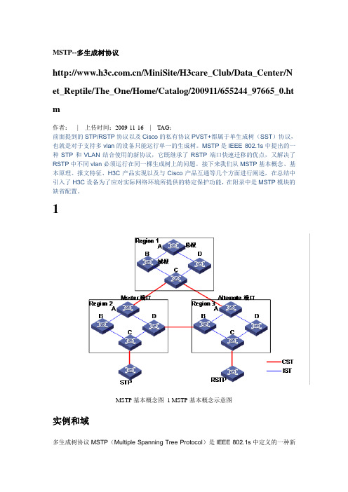
MSTP--多生成树协议/MiniSite/H3care_Club/Data_Center/Net_Reptile/The_One/Home/Catalog/200911/655244_97665_0.htm作者:| 上传时间:2009-11-16 | TAG:前面提到的STP/RSTP协议以及Cisco的私有协议PVST+都属于单生成树(SST)协议,也就是对于支持多vlan的设备只能运行单一的生成树。
MSTP是IEEE 802.1s中提出的一种STP和VLAN结合使用的新协议,它既继承了RSTP端口快速迁移的优点,又解决了RSTP中不同vlan必须运行在同一棵生成树上的问题。
接下来我们从MSTP基本概念、基本原理、报文特征、H3C产品实现以及与Cisco产品互通等几个方面进行阐述,在总结中引入了H3C设备为了应对实际网络环境所提供的特定保护功能,在附录中是MSTP模块的缺省配置。
1MSTP基本概念图1 MSTP基本概念示意图实例和域多生成树协议MSTP(Multiple Spanning Tree Protocol)是IEEE 802.1s中定义的一种新型生成树协议。
简单说来,STP/RSTP是基于端口的,PVST+是基于VLAN的,而MSTP 是基于实例的。
与STP/RSTP和PVST+相比,MSTP中引入了“实例”(Instance)和“域”(Region) “的概念。
所谓“实例”就是多个VLAN的一个集合,这种通过多个VLAN捆绑到一个实例中去的方法可以节省通信开销和资源占用率。
MSTP各个实例拓扑的计算是独立的,在这些实例上就可以实现负载均衡。
使用的时候,可以把多个相同拓扑结构的VLAN 映射到某一个实例中,这些VLAN在端口上的转发状态将取决于对应实例在MSTP里的转发状态。
所谓“域”,由域名(Configuration Name)、修订级别(Revision Level)、格式选择器(Configuration Identifier Format Selector[1])、VLAN与实例的映射关系(mapping of VIDs to spanning trees),其中域名、格式选择器和修订级别在BPDU报文中都有相关字段,而VLAN 与实例的映射关系在BPDU报文中表现摘要信息(Configuration Digest),该摘要是根据映射关系计算得到的一个16字节签名。
H3C交换机vrrp+mstp配置实例

H3C交换机vrrp+mstp配置实例交换机vrrp+mstp配置实例⼀、组⽹需求1、switch a 、switch b选⽤两台锐捷的s5750 ;switch c 、shwich d 选⽤锐捷的s3750和s37602、全⽹共有两个业务vlan ,为vlan 10 、vlan 203、Switch a 、switch b 都分别对两vlan起⽤两vrrp组,实现两组的业务的负载分担和备份。
4、Switch a、switch b、switch c、switch d 都起⽤mstp多⽣成数协议,并且所有设备都属于同⼀个mst域,且实例映射⼀致(vlan 10映射实例1、vlan 20映射实例2 其他vlan映射默认实例0)。
5、Vlan 10业务以switch a为根桥;vlan 20业务以switch b为根桥;实现阻断⽹络环路,并能实现不同vlan数据流负载分担功能。
⼆、组⽹图三、配置步骤Switch a配置:s1#show runBuilding configuration...Current configuration : 1651 bytesversion RGNOS 10.2.00(2), Release(29287)(Tue Dec 25 20:39:14 CST 2007 -ngcf49) hostname s1 co-operate enable!!!vlan 1!vlan 10!vlan 20!!no service password-encryption!spanning-tree 开启⽣成树(默认为mstp)spanning-tree mst configuration 进⼊mst配置模式revision 1 指定MST revision number 为1name region1 指定mst配置名称instance 0 vlan 1-9, 11-19, 21-4094 缺省情况下vlan都属于实例0instance 1 vlan 10 ⼿⼯指定vlan10属于实例1instance 2 vlan 20 ⼿⼯指定vlan20属于实例2spanning-tree mst 1 priority 0 指定实例1的优先级为0(为根桥)spanning-tree mst 2 priority 4096 指定实例2的优先级为4096interface GigabitEthernet 0/1switchport access vlan 10 配置g0/1属于vlan10!interface GigabitEthernet 0/2switchport access vlan 20 配置g0/2属于vlan 20!interface GigabitEthernet 0/3!..interface GigabitEthernet 0/24 设置g0/24为trunk接⼝且允许vlan10/20通过switchport mode trunkinterface VLAN 10 创建vlan 10 svi接⼝ip address 192.168.10.1 255.255.255.0 配置ip地址vrrp 1 priority 120 配置vrrp组1 优先级为120vrrp 1 ip 192.168.10.254 配置vrrp组1虚拟ip地址为192.168.10.254!interface VLAN 20 创建vlan 20 svi接⼝ip address 192.168.20.1 255.255.255.0 配置ip地址vrrp 2 ip 192.168.20.254 配置vrrp组2虚拟ip地址为192.168.20.254默认vrrp组的优先级为100默认不显⽰!line con 0line vty 0 4logins1#show vlanVLAN Name Status Ports---- -------------------------------- --------- ----------------------------------1 VLAN0001 STA TIC Gi0/3, Gi0/4, Gi0/5, Gi0/6Gi0/7, Gi0/8, Gi0/9, Gi0/10Gi0/11, Gi0/12, Gi0/13, Gi0/14Gi0/15, Gi0/16, Gi0/17, Gi0/18Gi0/19, Gi0/20, Gi0/21, Gi0/22Gi0/23, Gi0/2410 VLAN0010 STATIC Gi0/1, Gi0/2420 VLAN0020 STATIC Gi0/2, Gi0/24Switch b配置:s2#show runBuilding configuration...Current configuration : 1607 bytes!version RGNOS 10.2.00(2), Release(27932)(Thu Dec 13 10:32:09 CST 2007 -ngcf31) hostname s2 !!!!vlan 10!vlan 20!!no service password-encryption!spanning-treespanning-tree mst configuration revision 1name region1instance 0 vlan 1-9, 11-19, 21-4094 instance 1 vlan 10instance 2 vlan 20spanning-tree mst 1 priority 4096 spanning-tree mst 2 priority 0 interface GigabitEthernet 0/1 switchport access vlan 10!interface GigabitEthernet 0/2 switchport access vlan 20!..interface GigabitEthernet 0/24 switchport mode trunk!interface VLAN 10ip address 192.168.10.2 255.255.255.0 vrrp 1 ip 192.168.10.254!interface VLAN 20ip address 192.168.20.2 255.255.255.0vrrp 2 ip 192.168.20.254!line con 0line vty 0 4login!!ends2#show vlanVLAN Name Status Ports---- -------------------------------- --------- -----------------------------------1 VLAN0001 STA TIC Gi0/3, Gi0/4, Gi0/5, Gi0/6Gi0/7, Gi0/8, Gi0/9, Gi0/10Gi0/11, Gi0/12, Gi0/13, Gi0/14Gi0/15, Gi0/16, Gi0/17, Gi0/18Gi0/19, Gi0/20, Gi0/21, Gi0/22Gi0/23, Gi0/2410 VLAN0010 STATIC Gi0/1, Gi0/2420 VLAN0020 STATIC Gi0/2, Gi0/24Switch c配置:s3#show runBuilding configuration...Current configuration : 1540 bytes!version RGNOS 10.2.00(2), Release(28794)(Fri Dec 21 09:27:15 CST 2007 -ngcf32) hostname s3 !vlan 1!vlan 10!!service password-encryption!spanning-tree mst configuration revision 1name region1instance 0 vlan 1-9, 11-19, 21-4094 instance 1 vlan 10instance 2 vlan 20spanning-tree mst 1 priority 0 spanning-tree mst 2 priority 4096 interface FastEthernet 0/1 switchport access vlan 10!interface FastEthernet 0/2 switchport access vlan 10!..interface GigabitEthernet 0/25!interface GigabitEthernet 0/26!interface GigabitEthernet 0/27!interface GigabitEthernet 0/28!interface VLAN 10ip address 192.168.10.3 255.255.255.0 !ip route 0.0.0.0 0.0.0.0 192.168.10.254 !!line con 0line vty 0 4loginSwitch d配置:Building configuration...Current configuration : 1066 bytes!version RGNOS 10.2.00(2), Release(27932)(Thu Dec 13 10:31:41 CST 2007 -ngcf32) hostname s4 !vlan 1!vlan 20!!no service password-encryption!spanning-treespanning-tree mst configurationrevision 1name region1instance 0 vlan 1-9, 11-19, 21-4094instance 1 vlan 10instance 2 vlan 20spanning-tree mst 1 priority 4096spanning-tree mst 2 priority 0interface GigabitEthernet 0/1switchport access vlan 20!interface GigabitEthernet 0/2switchport access vlan 20!..interface GigabitEthernet 0/12!interface VLAN 20ip address 192.168.20.3 255.255.255.0!!!ip route 0.0.0.0 0.0.0.0 192.168.20.254!!line con 0line vty 0 4login!四、查看vrrp、mstp信息Switch a 信息:s1#show vrrp 查看vrrp 信息VLAN 10 - Group 1State is MasterVirtual IP address is 192.168.10.254 configured Virtual MAC address is 0000.5e00.0101 Advertisement interval is 1 secPreemption is enabledmin delay is 0 secPriority is 120Master Router is 192.168.10.1 (local), priority is 120 Master Advertisement interval is 1 secMaster Down interval is 3 secVLAN 20 - Group 2State is BackupVirtual IP address is 192.168.20.254 configured Virtual MAC address is 0000.5e00.0102 Advertisement interval is 1 secPreemption is enabledmin delay is 0 secPriority is 100Master Router is 192.168.20.2 , priority is 120 Master Advertisement interval is 1 secMaster Down interval is 3 secs1#s1#s1#show spanning-tree interface gigabitEthernet 0/1 查看g0/1接⼝stp状态信息PortAdminPortFast : Disabled PortOperPortFast : Disabled PortAdminAutoEdge : Enabled PortOperAutoEdge : Disabled PortAdminLinkType : auto PortOperLinkType : point-to-point PortBPDUGuard : DisabledPortBPDUFilter : Disabled###### MST 0 vlans mapped :1-9, 11-19, 21-4094 PortState : forwardingPortPriority : 128PortDesignatedRoot : 8000.001a.a909.8fe0 PortDesignatedCost : 0 PortDesignatedBridge :8000.00d0.f836.ed70 PortDesignatedPort : 8001 PortForwardTransitions : 6 PortAdminPathCost : 200000 PortOperPathCost : 200000 PortRole : designatedPort###### MST 1 vlans mapped :10PortState : forwardingPortPriority : 128PortDesignatedRoot : 0001.00d0.f823.ef82 PortDesignatedCost : 0 PortDesignatedBridge :0001.00d0.f823.ef82 PortDesignatedPort : 8001 PortForwardTransitions : 5 PortAdminPathCost : 200000 PortOperPathCost : 200000 PortRole : rootPort###### MST 2 vlans mapped :20PortState : forwardingPortPriority : 128PortDesignatedRoot : 0002.001a.a909.8fe0 PortDesignatedCost : 0 PortDesignatedBridge :1002.00d0.f836.ed70 PortDesignatedPort : 8001 PortForwardTransitions : 4 PortAdminPathCost : 200000 PortOperPathCost : 200000 PortRole : designatedPorts1#s1#s1#show spanning-tree interface gigabitEthernet 0/2 查看g0/2接⼝stp状态信息PortAdminPortFast : Disabled PortOperPortFast : DisabledPortAdminAutoEdge : EnabledPortOperAutoEdge : DisabledPortAdminLinkType : autoPortOperLinkType : point-to-pointPortBPDUGuard : DisabledPortBPDUFilter : Disabled###### MST 0 vlans mapped :1-9, 11-19, 21-4094PortState : forwardingPortPriority : 128PortDesignatedRoot : 8000.001a.a909.8fe0PortDesignatedBridge :8000.00d0.f836.ed70PortDesignatedPort : 8002PortForwardTransitions : 5PortAdminPathCost : 20000PortOperPathCost : 20000PortRole : designatedPort###### MST 1 vlans mapped :10PortState : forwardingPortPriority : 128PortDesignatedRoot : 0001.00d0.f823.ef82PortDesignatedCost : 0PortDesignatedBridge :0001.00d0.f836.ed70PortDesignatedPort : 8002PortForwardTransitions : 4PortAdminPathCost : 20000PortOperPathCost : 20000PortRole : designatedPort###### MST 2 vlans mapped :20PortState : discardingPortPriority : 128PortDesignatedRoot : 0002.001a.a909.8fe0PortDesignatedCost : 0PortDesignatedBridge :0002.00d0.f8d7.ae12PortDesignatedPort : 8002PortForwardTransitions : 3PortAdminPathCost : 20000PortOperPathCost : 20000PortRole : alternatePorts1#s1#s1#show spanning-tree interface gigabitEthernet 0/24 g0/24接⼝stp状态信息PortAdminPortFast : Disabled PortOperPortFast : DisabledPortAdminAutoEdge : EnabledPortOperAutoEdge : DisabledPortOperLinkType : point-to-pointPortBPDUGuard : DisabledPortBPDUFilter : Disabled###### MST 0 vlans mapped :1-9, 11-19, 21-4094PortState : forwardingPortPriority : 128PortDesignatedRoot : 8000.001a.a909.8fe0PortDesignatedCost : 0PortDesignatedBridge :8000.001a.a909.8fe0PortDesignatedPort : 8018PortForwardTransitions : 5PortAdminPathCost : 20000PortOperPathCost : 20000PortRole : rootPort###### MST 1 vlans mapped :10PortState : forwardingPortPriority : 128PortDesignatedRoot : 0001.00d0.f823.ef82PortDesignatedCost : 0PortDesignatedBridge :0001.00d0.f836.ed70PortDesignatedPort : 8018PortForwardTransitions : 5PortAdminPathCost : 20000PortOperPathCost : 20000PortRole : designatedPort###### MST 2 vlans mapped :20PortState : forwardingPortPriority : 128PortDesignatedRoot : 0002.001a.a909.8fe0 PortDesignatedCost : 0PortDesignatedBridge :0002.001a.a909.8fe0 PortDesignatedPort : 8018 PortForwardTransitions : 4 PortAdminPathCost : 20000PortOperPathCost : 20000PortRole : rootPorts1#Switch b 信息:s2#show vrrpVLAN 10 - Group 1State is BackupVirtual IP address is 192.168.10.254 configured Virtual MAC address is 0000.5e00.0101 Advertisement interval is 1 sec Preemption is enabledmin delay is 0 secPriority is 100Master Router is 192.168.10.1 , priority is 120 Master Advertisement interval is 1 secMaster Down interval is 3 secVLAN 20 - Group 2State is MasterVirtual IP address is 192.168.20.254 configured Virtual MAC address is 0000.5e00.0102 Advertisement interval is 1 sec Preemption is enabledmin delay is 0 secPriority is 120Master Router is 192.168.20.2 (local), priority is 120 Master Advertisement interval is 1 secMaster Down interval is 3 secs2#s2#s2#s2#s2#s2#s2#show spanning-tree interface gigabitEthernet 0/1PortAdminPortFast : Disabled PortOperPortFast : Disabled PortAdminAutoEdge : Enabled PortOperAutoEdge : Disabled PortAdminLinkType : auto PortOperLinkType : point-to-point PortBPDUGuard : DisabledPortBPDUFilter : Disabled###### MST 0 vlans mapped :1-9, 11-19, 21-4094 PortState : forwardingPortPriority : 128PortDesignatedRoot : 8000.001a.a909.8fe0 PortDesignatedCost : 0 PortDesignatedBridge :8000.001a.a909.8fe0 PortDesignatedPort : 8001 PortForwardTransitions : 1 PortAdminPathCost : 200000 PortOperPathCost : 200000 PortRole : designatedPort###### MST 1 vlans mapped :10PortState : forwardingPortPriority : 128PortDesignatedRoot : 0001.00d0.f823.ef82 PortDesignatedCost : 0 PortDesignatedBridge :0001.00d0.f823.ef82 PortDesignatedPort : 8002 PortForwardTransitions : 2 PortAdminPathCost : 200000 PortOperPathCost : 200000PortRole : rootPort###### MST 2 vlans mapped :20PortState : forwardingPortPriority : 128PortDesignatedRoot : 0002.001a.a909.8fe0 PortDesignatedCost : 0 PortDesignatedBridge :0002.001a.a909.8fe0 PortDesignatedPort : 8001 PortForwardTransitions : 1 PortAdminPathCost : 200000 PortOperPathCost : 200000 PortRole : designatedPorts2#s2#s2#s2#show spanning-tree interface gigabitEthernet 0/2 PortAdminPortFast : Disabled PortOperPortFast : Disabled PortAdminAutoEdge : Enabled PortOperAutoEdge : Disabled PortAdminLinkType : auto PortOperLinkType : point-to-point PortBPDUGuard : DisabledPortBPDUFilter : Disabled###### MST 0 vlans mapped :1-9, 11-19, 21-4094 PortState : forwardingPortPriority : 128PortDesignatedRoot : 8000.001a.a909.8fe0 PortDesignatedCost : 0 PortDesignatedBridge :8000.001a.a909.8fe0 PortDesignatedPort : 8002 PortForwardTransitions : 1 PortAdminPathCost : 20000 PortOperPathCost : 20000 PortRole : designatedPort###### MST 1 vlans mapped :10PortState : forwardingPortPriority : 128PortDesignatedRoot : 0001.00d0.f823.ef82 PortDesignatedCost : 0 PortDesignatedBridge :1001.001a.a909.8fe0 PortDesignatedPort : 8002 PortForwardTransitions : 2 PortAdminPathCost : 20000 PortOperPathCost : 20000 PortRole : designatedPort###### MST 2 vlans mapped :20PortState : forwardingPortPriority : 128PortDesignatedRoot : 0002.001a.a909.8fe0 PortDesignatedCost : 0PortDesignatedBridge :0002.001a.a909.8fe0 PortDesignatedPort : 8002 PortForwardTransitions : 1 PortAdminPathCost : 20000PortOperPathCost : 20000PortRole : designatedPorts2#s2#s2#s2#s2#show spanning-tree interface gigabitEthernet 0/24 PortAdminPortFast : Disabled PortOperPortFast : Disabled PortAdminAutoEdge : Enabled PortOperAutoEdge : Disabled PortAdminLinkType : autoPortOperLinkType : point-to-point PortBPDUGuard : DisabledPortBPDUFilter : Disabled###### MST 0 vlans mapped :1-9, 11-19, 21-4094 PortState : forwardingPortPriority : 128PortDesignatedRoot : 8000.001a.a909.8fe0 PortDesignatedCost : 0PortDesignatedBridge :8000.001a.a909.8fe0 PortDesignatedPort : 8018 PortForwardTransitions : 1 PortAdminPathCost : 20000PortOperPathCost : 20000PortRole : designatedPort###### MST 1 vlans mapped :10PortState : discardingPortPriority : 128PortDesignatedRoot : 0001.00d0.f823.ef82 PortDesignatedCost : 0PortDesignatedBridge :0001.00d0.f836.ed70 PortDesignatedPort : 8018 PortForwardTransitions : 1 PortAdminPathCost : 20000PortOperPathCost : 20000PortRole : alternatePort###### MST 2 vlans mapped :20PortState : forwardingPortPriority : 128PortDesignatedRoot : 0002.001a.a909.8fe0 PortDesignatedCost : 0 PortDesignatedBridge :0002.001a.a909.8fe0 PortDesignatedPort : 8018 PortForwardTransitions : 1 PortAdminPathCost : 20000 PortOperPathCost : 20000PortRole : designatedPorts2#Switch c 信息:s3#show spanning-tree interface fastEthernet 0/1 PortAdminPortFast : Disabled PortOperPortFast : Disabled PortAdminAutoEdge : Enabled PortOperAutoEdge : Disabled PortAdminLinkType : auto PortOperLinkType : point-to-point PortBPDUGuard : DisabledPortBPDUFilter : Disabled###### MST 0 vlans mapped :1-9, 11-19, 21-4094 PortState : discardingPortPriority : 128PortDesignatedRoot : 8000.001a.a909.8fe0 PortDesignatedCost : 0 PortDesignatedBridge :8000.00d0.f836.ed70 PortDesignatedPort : 8001 PortForwardTransitions : 1 PortAdminPathCost : 200000 PortOperPathCost : 200000 PortRole : alternatePort###### MST 1 vlans mapped :10PortState : forwardingPortPriority : 128PortDesignatedRoot : 0001.00d0.f823.ef82PortDesignatedCost : 0 PortDesignatedBridge :0001.00d0.f823.ef82 PortDesignatedPort : 8001 PortForwardTransitions : 1 PortAdminPathCost : 200000 PortOperPathCost : 200000PortRole : designatedPort###### MST 2 vlans mapped :20PortState : discardingPortPriority : 128PortDesignatedRoot : 0002.001a.a909.8fe0 PortDesignatedCost : 0 PortDesignatedBridge :1002.00d0.f836.ed70 PortDesignatedPort : 8001 PortForwardTransitions : 0 PortAdminPathCost : 200000 PortOperPathCost : 200000 PortRole : alternatePorts3#s3#s3#s3#s3#show spanning-tree interface fastEthernet 0/2 PortAdminPortFast : Disabled PortOperPortFast : Disabled PortAdminAutoEdge : Enabled PortOperAutoEdge : Disabled PortAdminLinkType : auto PortOperLinkType : point-to-point PortBPDUGuard : DisabledPortBPDUFilter : Disabled###### MST 0 vlans mapped :1-9, 11-19, 21-4094 PortState : forwardingPortPriority : 128PortDesignatedRoot : 8000.001a.a909.8fe0 PortDesignatedCost : 0 PortDesignatedBridge :8000.001a.a909.8fe0 PortDesignatedPort : 8001 PortForwardTransitions : 1 PortAdminPathCost : 200000 PortOperPathCost : 200000 PortRole : rootPort###### MST 1 vlans mapped :10PortState : forwardingPortPriority : 128PortDesignatedRoot : 0001.00d0.f823.ef82 PortDesignatedCost : 0 PortDesignatedBridge :0001.00d0.f823.ef82 PortDesignatedPort : 8002 PortForwardTransitions : 2 PortAdminPathCost : 200000 PortOperPathCost : 200000 PortRole : designatedPort###### MST 2 vlans mapped :20PortState : forwardingPortPriority : 128PortDesignatedRoot : 0002.001a.a909.8fe0 PortDesignatedCost : 0 PortDesignatedBridge :0002.001a.a909.8fe0 PortDesignatedPort : 8001 PortForwardTransitions : 1 PortAdminPathCost : 200000 PortOperPathCost : 200000 PortRole : rootPorts3#Switch d 信息:s4#show spanning-tree interface gigabitEthernet 0/1 PortAdminPortFast : Disabled PortOperPortFast : Disabled PortAdminAutoEdge : Enabled PortOperAutoEdge : Disabled PortAdminLinkType : auto PortOperLinkType : point-to-point PortBPDUGuard : DisabledPortBPDUFilter : Disabled###### MST 0 vlans mapped :1-9, 11-19, 21-4094 PortState : forwardingPortPriority : 128PortDesignatedRoot : 8000.001a.a909.8fe0 PortDesignatedCost : 0 PortDesignatedBridge :8000.001a.a909.8fe0 PortDesignatedPort : 8002 PortForwardTransitions : 1 PortAdminPathCost : 20000 PortOperPathCost : 20000 PortRole : rootPort###### MST 1 vlans mapped :10PortState : discardingPortPriority : 128PortDesignatedRoot : 0001.00d0.f823.ef82 PortDesignatedCost : 0 PortDesignatedBridge :1001.001a.a909.8fe0 PortDesignatedPort : 8002 PortForwardTransitions : 1 PortAdminPathCost : 20000 PortOperPathCost : 20000 PortRole : alternatePort###### MST 2 vlans mapped :20PortState : forwardingPortPriority : 128PortDesignatedRoot : 0002.001a.a909.8fe0 PortDesignatedCost : 0 PortDesignatedBridge :0002.001a.a909.8fe0 PortDesignatedPort : 8002 PortForwardTransitions : 1 PortAdminPathCost : 20000 PortOperPathCost : 20000 PortRole : rootPorts4#s4#s4#s4#show spanning-tree interface gigabitEthernet 0/2 PortAdminPortFast : Disabled PortOperPortFast : Disabled PortAdminAutoEdge : Enabled PortOperAutoEdge : Disabled PortAdminLinkType : auto PortOperLinkType : point-to-point PortBPDUGuard : Disabled。
H3C S9500交换机VRRP+MSTP配置举例
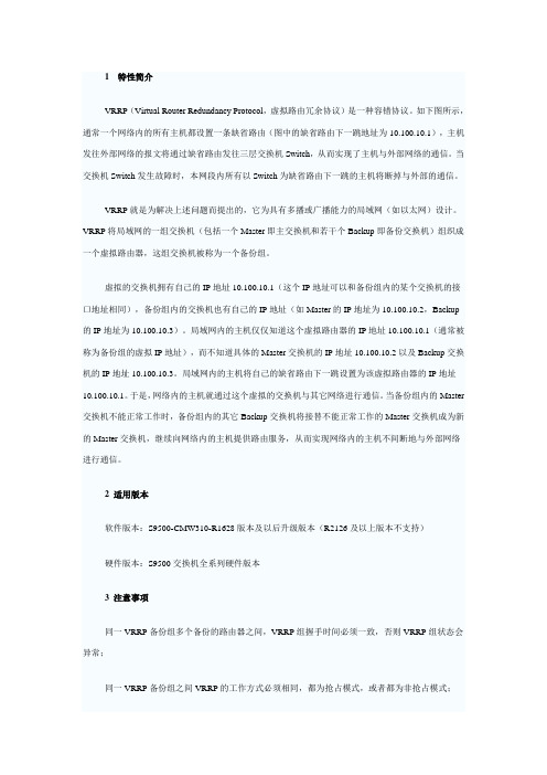
1 特性简介VRRP(Virtual Router Redundancy Protocol,虚拟路由冗余协议)是一种容错协议。
如下图所示,通常一个网络内的所有主机都设置一条缺省路由(图中的缺省路由下一跳地址为10.100.10.1),主机发往外部网络的报文将通过缺省路由发往三层交换机Switch,从而实现了主机与外部网络的通信。
当交换机Switch发生故障时,本网段内所有以Switch为缺省路由下一跳的主机将断掉与外部的通信。
VRRP就是为解决上述问题而提出的,它为具有多播或广播能力的局域网(如以太网)设计。
VRRP将局域网的一组交换机(包括一个Master即主交换机和若干个Backup即备份交换机)组织成一个虚拟路由器,这组交换机被称为一个备份组。
虚拟的交换机拥有自己的IP地址10.100.10.1(这个IP地址可以和备份组内的某个交换机的接口地址相同),备份组内的交换机也有自己的IP地址(如Master的IP地址为10.100.10.2,Backup 的IP地址为10.100.10.3)。
局域网内的主机仅仅知道这个虚拟路由器的IP地址10.100.10.1(通常被称为备份组的虚拟IP地址),而不知道具体的Master交换机的IP地址10.100.10.2以及Backup交换机的IP地址10.100.10.3。
局域网内的主机将自己的缺省路由下一跳设置为该虚拟路由器的IP地址10.100.10.1。
于是,网络内的主机就通过这个虚拟的交换机与其它网络进行通信。
当备份组内的Master 交换机不能正常工作时,备份组内的其它Backup交换机将接替不能正常工作的Master交换机成为新的Master交换机,继续向网络内的主机提供路由服务,从而实现网络内的主机不间断地与外部网络进行通信。
2 适用版本软件版本:S9500-CMW310-R1628版本及以后升级版本(R2126及以上版本不支持)硬件版本:S9500交换机全系列硬件版本3 注意事项同一VRRP备份组多个备份的路由器之间,VRRP组握手时间必须一致,否则VRRP组状态会异常;同一VRRP备份组之间VRRP的工作方式必须相同,都为抢占模式,或者都为非抢占模式;必须在配置VRRP组之前启用vrrp ping-enable功能,否则无法ping通VRRP虚地址;VRRP监控端口只能监控VLAN接口地址,无法监控某个具体的端口;VRRP组的hello时间一般不建议修改;如果VRRP组数较多,可以考虑把各组的hello时间分别设置成2、3、5、7等互质数,减少VRRP hello报文对CPU的冲击。
H3C STP概念

1 概述1.1 产生背景在二层交换网络中,一旦存在环路就会造成报文在环路内不断循环和增生,产生广播风暴,从而占用所有的有效带宽,使网络变得不可用。
在这种环境下生成树协议应运而生,生成树协议是一种二层管理协议,它通过有选择性地阻塞网络冗余链路来达到消除网络二层环路的目的,同时具备链路的备份功能。
生成树协议和其他协议一样,是随着网络的不断发展而不断更新换代的。
最初被广泛应用的是IEEE 802.1D-1998 STP(Spanning Tree Protocol,生成树协议),随后以它为基础产生了IEEE 802.1w RSTP(Rapid Spanning Tree Protocol,快速生成树协议)、PVST(Per VLAN Spanning Tree,每VLAN生成树)协议和IEEE 802.1s MSTP(Multiple Spanning Tree Protocol,多生成树协议)。
1.1.1 STPSTP包含了两个含义,狭义的STP是指IEEE 802.1D-1998中定义的STP协议,广义的STP是指包括IEEE 802.1D-1998定义的STP协议以及各种在它的基础上经过改进的生成树协议。
本文中的STP均指狭义的STP。
STP的基本思想十分简单。
自然界中生长的树是不会出现环路的,如果网络也能够像一棵树一样生长就不会出现环路。
于是,STP中定义了根桥(Root Bridge)、根端口(Root Port)、指定端口(Designated Port)、路径开销(Path Cost)等概念,目的就在于通过构造一棵树的方法达到裁剪冗余环路的目的,同时实现链路备份和路径最优化。
用于构造这棵树的算法称为生成树算法(Spanning Tree Algorithm)。
要实现这些功能,网桥之间必须要进行一些信息的交互,这些信息交互单元就称为BPDU(Bridge Protocol Data Unit,桥协议数据单元),也称为配置消息。
MSTP配置要点概述1
MSTP配置要点概述1、MSTP基本原理MSTP是ISP将用户的以太帧封装到SDH内传输的技术,和传统SDH点对点链路不同之处在于:用户可以灵活开通任意带宽而不再受限于2M带宽的叠加。
对于用户而言,ISP的MSTP网络就是一个巨大的交换机。
用户通过给每个节点分配一个vlan的方式实现互联。
因此,每个分支就相当于一个vlan,而中心端相当于trunk,每个子接口对应一个vlan。
因此,用户需要为每个分支分配vlan编号和对应的IP地址,vlan编号需要和ISP共享,ISP负责将每个VLAN和SDH通道一一对应起来。
2、MSTP的线路监测配置以太接口下的IP配置和原有的串口或E1口配置没有什么区别,只是将原有接口的配置迁移到以太口下而已。
但是由于以太口的物理性质和串口不同,导致端口监测和QoS配置有较大差异。
以太口因为不是点对点性质,因此当线路中断时,路由器和MSTP设备的互联还是完好的,因此端口不会down,如果使用的是静态路由,则路由表不会更新,导致断网。
因此需要使用额外的PING检查配置来克服这点,不同厂家配置有所不同。
Cisco:使用IP SLA。
IP SLA即服务质量保证,实际上就是由路由器主动的通过PING、TCP SYN 等数据包去检查某项应用的可用状态,然后将检查结果反馈给路由器(即track),路由器随机做出反应。
在MSTP中我们使用PING来检查线路的通断。
命令如下:ip sla monitor 1type echo protocol ipIcmpEcho 1.1.1.1 source-ipaddr 1.1.1.2frequency 10timeout 500vrf XXX!ip sla monitor schedule 1 start-time now life forever!track 1 rtr 1 state!ip route **** **** next-hop track 1本配置中,启用一个编号为1的SLA,使用ICMP从本地接口地址ping对端设备地址做检查,并配置ping测试的周期为10秒,每次ping的超时时间为500毫秒,并放入某vrf内。
H3C MSTP端口状态介绍
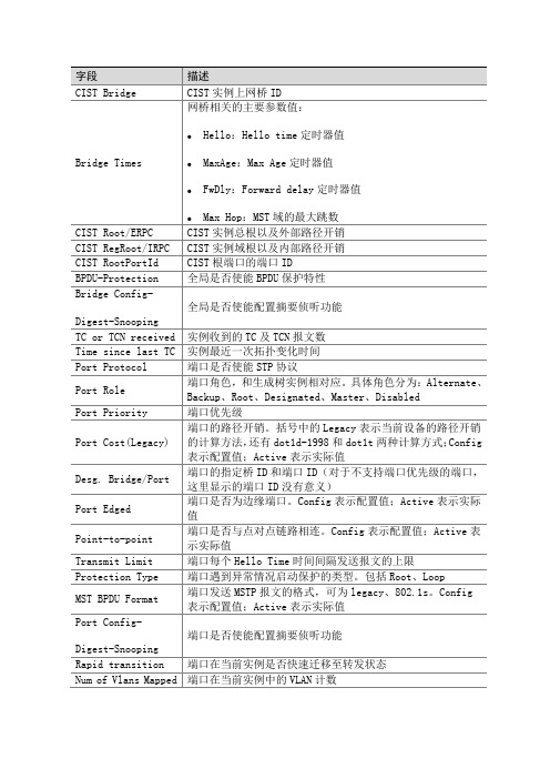
端口是否为边缘端口。Config表示配置值;Active表示实际值
Point-to-point
端口是否与点对点链路相连。Config表示配置值;Active表示实际值
Transmit Limit
端口每个Hello Time时间间隔发送报文的上限
Protection Type
端口遇到异常情况启动保护的类型。包括Root、Loop
BPDU Received
端口接收报文计数
实例收到的TC及TCN报文数
Time since last TC
实例最近一次拓扑变化时间
Port Protocol
端口是否使能STP协议
Port Role
端口角色,和生成树实例相对应。具体角色分为:Alternate、Backup、Root、Designated、Master、Disabled
Port Priority
MST BPDU Format
端口发送MSTP报文的格式,可为legacy、802.1s。Config表示配置值;Active表示实际值
Port Config-
Digest-Snooping
端口是否使能配置摘要侦听功能
Rapid transition
端口在当前实例是否快速迁移至转发状态
Num of Vlans Mapped
端口在当前实例中的VLAN计数
Poime定时器值
MaxAge:Max Age定时器值
FwDly:Forward delay定时器值
MsgAge:Message Age定时器值
Remain Hop:剩余跳数
BPDU Sent
端口发送报文计数
字段
描述
MSTP配置

目录第1章 MSTP配置...................................................................................................................1-11.1 MSTP简介..........................................................................................................................1-11.1.1 STP简介..................................................................................................................1-11.1.2 MSTP简介...............................................................................................................1-91.1.3 协议规范................................................................................................................1-151.2 配置任务简介...................................................................................................................1-151.3 配置根桥...........................................................................................................................1-161.3.1 配置MST域............................................................................................................1-161.3.2 指定当前设备为根桥或备份根桥............................................................................1-181.3.3 配置MSTP的工作模式...........................................................................................1-191.3.4 配置当前设备的优先级..........................................................................................1-201.3.5 配置MST域的最大跳数..........................................................................................1-201.3.6 配置交换网络的网络直径.......................................................................................1-211.3.7 配置MSTP的时间参数...........................................................................................1-221.3.8 配置超时时间因子..................................................................................................1-231.3.9 配置端口的最大发送速率.......................................................................................1-241.3.10 配置端口为边缘端口............................................................................................1-251.3.11 配置端口是否与点对点链路相连..........................................................................1-261.3.12 配置端口识别/发送MSTP报文的方式..................................................................1-271.3.13 开启MSTP特性....................................................................................................1-281.4 配置叶子节点...................................................................................................................1-281.4.1 配置MST域............................................................................................................1-281.4.2 配置MSTP的工作模式...........................................................................................1-291.4.3 配置超时时间因子..................................................................................................1-291.4.4 配置端口的最大发送速率.......................................................................................1-291.4.5 配置端口为边缘端口..............................................................................................1-291.4.6 配置端口的Path Cost............................................................................................1-291.4.7 配置端口的优先级..................................................................................................1-311.4.8 配置端口是否与点对点链路相连............................................................................1-321.4.9 配置端口识别/发送MSTP报文的方式....................................................................1-321.4.10 开启MSTP特性....................................................................................................1-321.5 执行mCheck操作.............................................................................................................1-331.6 配置VLAN Ignore特性......................................................................................................1-341.6.1 VLAN Ignore特性简介...........................................................................................1-341.6.2 配置VLAN Ignore特性...........................................................................................1-341.6.3 VLAN Ignore特性配置举例....................................................................................1-351.7 配置摘要侦听特性............................................................................................................1-361.7.1 配置准备................................................................................................................1-361.7.2 配置摘要侦听特性..................................................................................................1-361.7.3 摘要侦听特性配置举例..........................................................................................1-37 1.8 配置No Agreement Check特性........................................................................................1-381.8.1 配置准备................................................................................................................1-391.8.2 配置No Agreement Check特性.............................................................................1-391.8.3 No Agreement Check特性配置举例......................................................................1-40 1.9 配置设备的保护功能........................................................................................................1-401.9.1 配置准备................................................................................................................1-421.9.2 配置BPDU保护功能...............................................................................................1-421.9.3 配置根保护功能.....................................................................................................1-431.9.4 配置环路保护功能..................................................................................................1-431.9.5 配置防止TC-BPDU报文攻击的保护功能...............................................................1-44 1.10 MSTP显示和维护...........................................................................................................1-45 1.11 MSTP典型配置举例.......................................................................................................1-45第1章 MSTP配置1.1 MSTP简介1.1.1 STP简介1. STP的用途STP(Spanning Tree Protocol,生成树协议)是根据IEEE(Institute of Electrical andElectronics Engineers,电气与电子工程师协会)制定的802.1D标准建立的,用于在局域网中消除数据链路层物理环路的协议。
H3C_STP_RSTP_MSTP协议原理及配置

Root Switch is 0001 Lowest Cost to Root = 7
Switch A BID =0001
Root Switch is 0001 Lowest Cost to Root = 3
Cost to Root =18 Switch B BID =0050 Cost to Root =7
Switch A BID =0001
Root Switch is 0001 Lowest Cost to Root = 3
Cost to Root =18 Switch B BID =0050 Cost to Root =7
Cost to Root =3 Switch C BID =1045 Cost to Root =22
11
如何确定根桥
I’m the Root Switch
I’m the Root Switch
Switch A BID =0001
I’m the Root Switch
Switch B BID =0050
Switch C BID =1045
Switch D BID =0030
I’m the Root Switch
Root Switch = 0001 Lowest Cost to Root = 11
22
BPDU交换过程
I’m the Root Switch Lowest Cost to Root = 0
Root Switch is 0001 Lowest Cost to Root = 7
14
如何确定根桥
I’m the Root Switch
Root Switch =0001
Switch A BID =0001
思科与H3C配置命令对比MSTPVRRP

思科与H3C配置命令对比MSTPVRRP思科与H3C配置命令对比MSTP VRRPMSTP,多生成树协议是IEEE 802.1s中定义的一种新型生成树协议。
简单说来,STP/RSTP是基于端口的,PVST+是基于VLAN的,而MSTP是基于实例的。
与STP/RSTP和PVST+相比,MSTP中引入了“实例”的概念。
它既可以实现快速收敛,又可以使不同VLAN的流量沿着各自的路径转发,从而利用冗余链路提供了更好的负载分担机制。
MSTP的基本思想地基于实例INSTANCE计算出多棵生成树,每一个实例可以包含一个或者多个VLAN,每一个VLAN只能映射到一个实例。
交换机通过配置多个实例,可以实现不同VLAN组之间的负载分担。
MSTP多生成树协议是IEEE标准协议,思科与H3C均可使用,但是配置命令上有所不同,下面具体来比较思科和H3C关于MSTP的配置命令。
如图所示:三台交换机都运行MSTP,配置两个实例,实例1对应VLAN 10,实例2对应VLAN 20。
思科MSTP配置如下:Switch(config)#vlan 10 //创建VLAN 10Switch(config)#vlan 20 //创建VLAN 20Switch(config)#spanning-tree mode mst //生成树工作模式配置为MSTPSwitch(config)#spanning-tree mst configuration //进入mstp 的.配置模式Switch(config-mst)#name jc //命名mstp的域名Switch(config-mst)#revision 0 //修订级别Switch(config-mst)#instance 1 vlan 10 //VLAN 10 加入实例1 Switch(config-mst)#instance 2 vlan 20 //VLAN 20 加入实例2 思科MSTP查看命令:Switch#show spanning-tree mst 查看MSTP的全部信息Switch#show spanning-tree mst configuration 查看实例映射信息H3C MSTP配置如下:[Switch]vlan 10 //创建VLAN 10[Switch]vlan 20 //创建VLAN 20[Switch]stp region-configuration //进入mstp配置模式[Switch-mst-region]region-name jc //命名mstp的域名[Switch-mst-region]revision-level 0 //修订级别[Switch-mst-region]instance 1 vlan 10 //VLAN 10 加入实例1 [Switch-mst-region]instance 2 vlan 20 //VLAN 20 加入实例2 [Switch-mst-region]active region-configuration //激活mst域的配置H3C MSTP查看命令:[Switch]display stp brief 查看生成树状态[Switch]dis stp region-configuration 查看域配置VRRP:虚拟路由冗余协议(Virtual Router Redundancy Protocol,简称VRRP)是由IETF提出的解决局域网中配置静态网关出现单点失效现象的路由协议,1998年已推出正式的RFC2338协议标准。
h3c双核心mstp+vrrp7500系列A
h3c双核心mstp+vrrp7500系列A[7506A]dis verH3C Comware Platform SoftwareComware Software, Version 5.20, Release 6305P03Copyright (c) 2004-2009 Hangzhou H3C Tech. Co., Ltd. All rights reserved.H3C S7506E uptime is 0 week, 2 days, 3 hours, 45 minutes MPU(M) 0:Uptime is 0 weeks,2 days,3 hours,45 minutesH3C S7506E MPU(M) with 1 BCM1125H ProcessorDRAM: 512M bytesFLASH: 64M bytesNVRAM: 512K bytesPCB 1 Version: VER.APCB 2 Version: VER.BBootrom Version: 209CPLD 1 Version: 001CPLD 2 Version: 001Release Version: H3C S7506E-6305P03Patch Version : NoneSlot 1 Without BoardLPU 2:Uptime is 0 weeks,2 days,3 hours,43 minutesH3C S7506E LPU with 1 BCM1122H ProcessorDRAM: 512M bytesFLASH: 0M bytesNVRAM: 0K bytesPCB 1 Version: VER.ABootrom Version: 205CPLD 1 Version: 002Release Version: H3C S7506E-6305P03 Patch Version : NoneLPU 3:Uptime is 0 weeks,2 days,3 hours,43 minutes H3C S7506E LPU with 1 BCM1122H Processor DRAM: 512M bytesFLASH: 0M bytesNVRAM: 0K bytesPCB 1 Version: VER.APCB 2 Version: VER.ABootrom Version: 205CPLD 1 Version: 002OAA Front Board: PR01OAPBRelease Version: H3C S7506E-6305P03 Patch Version : NoneLPU 4:Uptime is 0 weeks,2 days,3 hours,43 minutes H3C S7506E LPU with 1 BCM1122H Processor DRAM: 512M bytesFLASH: 0M bytesNVRAM: 0K bytesPCB 1 Version: VER.APCB 2 Version: VER.DBootrom Version: 205CPLD 1 Version: 002Release Version: H3C S7506E-6305P03 Patch Version : NoneSlot 5 Without BoardSlot 6 Without BoardSlot 7 Without BoardLPU 8:Uptime is 0 weeks,2 days,3 hours,44 minutesH3C S7506E LPU with 1 BCM1122H ProcessorDRAM: 512M bytesFLASH: 0M bytesNVRAM: 0K bytesPCB 1 Version: NABootrom Version: 205CPLD 1 Version: NARelease Version: H3C S7506E-6305P03Patch Version : NoneSlot 9 Without Board[7506A]dis deviceSlot No. Brd Type Brd Status Subslot Num Sft Ver Patch Ver0 LSQ1SRP12GB Master 0 S7500E-6305P03 None1 NONE Absent 0 NONE None2 LSQ1GT24SC Normal 0 S7500E-6305P03 None3 LSQ1FWBSC0 Normal 0 S7500E-6305P03 None4 LSQ1WCMB0 Normal 0 S7500E-6305P03 None5 NONE Absent 0 NONE None6 NONE Absent 0 NONE None7 NONE Absent 0 NONE None8 SRP12GBSLA VE Normal 0 S7500E-6305P03 None9 NONE Absent 0 NONE None[7506A]dis cuversion 5.20, Release 6305P03#sysname 7506A#domain default enable system#router id 1.1.1.1#telnet server enable#switch-mode standard#acl number 3000description ap_celuerule 0 deny tcp destination-port eq 445rule 5 deny tcp destination-port eq 4444rule 10 deny tcp destination-port eq 135rule 15 deny tcp destination-port eq 139rule 20 deny tcp destination-port eq 593rule 25 deny tcp destination-port eq 1434rule 30 deny tcp destination-port eq 138rule 35 deny tcp destination-port eq 137rule 40 deny tcp destination-port eq 5554rule 45 deny tcp destination-port eq 9996rule 50 deny udp destination-port eq 4444rule 55 deny udp destination-port eq 135rule 60 deny udp destination-port eq netbios-ssn rule 65 deny udp destination-port eq 445rule 70 deny udp destination-port eq 593rule 75 deny udp destination-port eq 1434rule 80 deny udp destination-port eq netbios-dgm rule 85 deny udp destination-port eq netbios-ns rule 90 deny udp destination-port eq 5554rule 95 deny udp destination-port eq 9996rule 100 deny ip destination 10.0.90.0 0.0.0.255rule 105 deny ip destination 10.0.0.0 0.0.63.255rule 110 deny ip destination 10.0.150.0 0.0.0.255 rule 115 deny ip destination 10.0.64.0 0.0.15.255 acl number 3001 description xinxi_celuerule 0 deny tcp destination-port eq 445rule 5 deny tcp destination-port eq 4444rule 10 deny tcp destination-port eq 135rule 15 deny tcp destination-port eq 139rule 20 deny tcp destination-port eq 593rule 25 deny tcp destination-port eq 1434rule 30 deny tcp destination-port eq 138rule 35 deny tcp destination-port eq 137rule 40 deny tcp destination-port eq 5554rule 45 deny tcp destination-port eq 9996rule 50 deny udp destination-port eq 4444rule 55 deny udp destination-port eq 135rule 60 deny udp destination-port eq netbios-ssn rule 65 deny udp destination-port eq 445rule 70 deny udp destination-port eq 593rule 75 deny udp destination-port eq 1434rule 80 deny udp destination-port eq netbios-dgm rule 85 deny udp destination-port eq netbios-ns rule 90 deny udp destination-port eq 5554rule 95 deny udp destination-port eq 9996rule 100 deny ip destination 10.0.90.0 0.0.0.255 rule 105 deny ip destination 10.0.0.0 0.0.63.255 rule 110 deny ip destination 10.0.150.0 0.0.0.255 rule 115 deny ip destination 10.0.80.0 0.0.0.255 acl number 3002description kefang_celuerule 0 deny tcp destination-port eq 445rule 5 deny tcp destination-port eq 4444rule 10 deny tcp destination-port eq 135rule 15 deny tcp destination-port eq 139rule 20 deny tcp destination-port eq 593rule 25 deny tcp destination-port eq 1434rule 30 deny tcp destination-port eq 138rule 35 deny tcp destination-port eq 137rule 40 deny tcp destination-port eq 5554rule 45 deny tcp destination-port eq 9996rule 50 deny udp destination-port eq 4444rule 55 deny udp destination-port eq 135rule 60 deny udp destination-port eq netbios-ssn rule 65 deny udp destination-port eq 445rule 70 deny udp destination-port eq 593rule 75 deny udp destination-port eq 1434rule 80 deny udp destination-port eq netbios-dgm rule 85 deny udp destination-port eq netbios-ns rule 90 deny udp destination-port eq 5554rule 95 deny udp destination-port eq 9996rule 100 deny ip destination 10.0.90.0 0.0.0.255 rule 105 deny ip destination 10.0.64.0 0.0.15.255 rule 110 deny ip destination 10.0.150.0 0.0.0.255 rule 115 deny ip destination 10.0.80.0 0.0.0.255 #vlan 1#vlan 4description zhulou kefangkongzhi 4 lou#vlan 5description zhulou kefangkongzhi 5 lou#vlan 6description zhulou kefangkongzhi 6 lou#vlan 7description zhulou kefangkongzhi 7 lou#vlan 8description zhulou kefangkongzhi 8 lou#vlan 9description zhulou kefangkongzhi 9 lou#vlan 10description zhulou kefangkongzhi 10 lou #vlan 11description zhulou kefangkongzhi 11 lou #vlan 12description zhulou kefangkongzhi 12 lou #vlan 13description zhulou kefangkongzhi 13 lou #vlan 14description zhulou kefangkongzhi 14 lou # vlan 15vlan 16description zhulou kefangkongzhi 16 lou # vlan 17description zhulou kefangkongzhi 17 lou # vlan 18description zhulou kefangkongzhi 18 lou # vlan 19description zhulou kefangkongzhi 19 lou # vlan 20description zhulou kefangkongzhi 20 lou # vlan 21description zhulou kefangkongzhi 21 lou # vlan 22description zhulou kefangkongzhi 22 lou # vlan 23description zhulou kefangkongzhi 23 lou # vlan 24description zhulou kefangkongzhi 24 lou # vlan 25description zhulou kefangkongzhi 25 lou # vlan 27description zhulou kefangkongzhi 27 lou # vlan 28description zhulou kefangkongzhi 28 lou # vlan 32description guibinlou kefangkongzhi 2 lou # vlan 33description guibinlou kefangkongzhi 3 lou # vlan 34vlan 35description guibinlou kefangkongzhi 5 lou # vlan 36description guibinlou kefangkongzhi 6 lou # vlan 37description guibinlou kefangkongzhi 7 lou # vlan 38description guibinlou kefangkongzhi 8 lou # vlan 40description qunlou xinxifabu#vlan 80description wlan#vlan 81description AP-guanli#vlan 90description guanli#vlan 100description zhulou xinxi 4-9 lou#vlan 101description zhulou xinxi 10-15 lou#vlan 102description zhulou xinxi 16-21 lou#vlan 103description zhulou xinxi 22-28 lou#vlan 104description guibinlou xinxi 2-8 lou#vlan 105description sushelou xinxi 1-8 lou#vlan 106description zhulou xinxi 9-17 lou#vlan 107description qunlou xinxi 1ceng 1#-4# # vlan 108description qunlou xinxi 1ceng 5#-7# # vlan 109description qunlou xinxi 2ceng 1#-2# # vlan 110description qunlou xinxi 2ceng 3##vlan 111description qunlou xinxi 2ceng 4#-6# # vlan 112description qunlou xinxi 3ceng 1#-2# # vlan 113description qunlou xinxi 3ceng 3#-6# # vlan 120description hulian 6608#vlan 150description guanlirenyuan#ftth#domain systemaccess-limit disablestate activeidle-cut disableself-service-url disable#traffic classifier ap_celue operator and if-match acl 3000 traffic classifier kefang_celue operator andif-match acl 3002traffic classifier xinxi_celue operator andif-match acl 3001##traffic behavior denyfilter deny#qos policy ap_celueclassifier ap_celue behavior denyqos policy kefang_celueclassifier kefang_celue behavior denyqos policy xinxi_celueclassifier xinxi_celue behavior deny##qos vlan-policy ap_celue vlan 80 inbound qos vlan-policyxinxi_celue vlan 100 inbound qos vlan-policy xinxi_celue vlan 101 inbound qos vlan-policy xinxi_celue vlan 102 inbound qos vlan-policy xinxi_celue vlan 103 inbound qos vlan-policy xinxi_celue vlan 104 inbound qos vlan-policy xinxi_celue vlan 105 inbound qos vlan-policy xinxi_celue vlan 106 inbound qos vlan-policy xinxi_celue vlan 107 inbound qos vlan-policy xinxi_celue vlan 108 inbound qos vlan-policy xinxi_celue vlan 109 inbound qos vlan-policy xinxi_celue vlan 110 inbound qos vlan-policy xinxi_celue vlan 111 inbound qos vlan-policy xinxi_celue vlan 112 inbound qos vlan-policy xinxi_celue vlan 113 inbound qos vlan-policy kefang_celue vlan 4 inbound qos vlan-policy kefang_celue vlan 5 inbound qos vlan-policy kefang_celue vlan 6 inbound qos vlan-policy kefang_celue vlan 7 inbound qos vlan-policy kefang_celue vlan 8 inbound qos vlan-policy kefang_celue vlan 9 inbound qos vlan-policy kefang_celue vlan 10 inbound qos vlan-policy kefang_celue vlan 11 inbound qos vlan-policy kefang_celue vlan 12 inbound qos vlan-policy kefang_celue vlan 13 inbound qos vlan-policy kefang_celue vlan 14 inbound qos vlan-policy kefang_celue vlan 15 inboundqos vlan-policy kefang_celue vlan 16 inbound qos vlan-policy kefang_celue vlan 17 inbound qos vlan-policy kefang_celue vlan 18 inbound qos vlan-policy kefang_celue vlan 19 inbound qos vlan-policy kefang_celue vlan 20 inbound qos vlan-policy kefang_celue vlan 21 inbound qos vlan-policy kefang_celue vlan 22 inbound qos vlan-policy kefang_celue vlan 23 inbound qos vlan-policy kefang_celue vlan 24 inbound qos vlan-policy kefang_celue vlan 25 inbound qos vlan-policy kefang_celue vlan 27 inbound qos vlan-policy kefang_celue vlan 28 inbound qos vlan-policy kefang_celue vlan 32 inbound qos vlan-policy kefang_celue vlan 33 inbound qos vlan-policykefang_celue vlan 34 inbound qos vlan-policy kefang_celue vlan 35 inbound qos vlan-policy kefang_celue vlan 36 inbound qos vlan-policy kefang_celue vlan 37 inbound qos vlan-policy kefang_celue vlan 38 inbound qos vlan-policy kefang_celue vlan 40 inbound#dhcp server ip-pool ap_guanlinetwork 10.0.81.0 mask 255.255.255.0 gateway-list 10.0.81.254expired unlimited#dhcp server ip-pool wlannetwork 10.0.80.0 mask 255.255.255.0 gateway-list 10.0.80.254dns-list 202.102.152.3expired unlimited#local-user adminpassword cipher .]@USE=B,53Q=^Q`MAF4<1!! service-type telnetlevel 3#stp instance 1 root secondarystp instance 2 root secondarystp instance 3 root primarystp instance 4 root primarystp enablestp region-configurationregion-name jiangquanjiudianinstance 1 vlan 4 to 28 32 to 38 40 instance 2 vlan 100 to 107instance 3 vlan 108 to 113instance 4 vlan 80 to 81 90 150active region-configuration#interface Bridge-Aggregation1#interface NULL0#interface Vlan-interface4description zhulou kefangkongzhi 4 lou ip address 10.0.4.251 255.255.255.0 vrrp vrid 4 virtual-ip 10.0.4.254#interface Vlan-interface5description zhulou kefangkongzhi 5 lou ip address 10.0.5.251 255.255.255.0 vrrp vrid 5 virtual-ip 10.0.5.254#interface Vlan-interface6description zhulou kefangkongzhi 6 lou ip address 10.0.6.251 255.255.255.0 vrrp vrid 6 virtual-ip 10.0.6.254#interface Vlan-interface7description zhulou kefangkongzhi 7 lou ip address 10.0.7.251 255.255.255.0 vrrp vrid 7 virtual-ip 10.0.7.254#interface Vlan-interface8description zhulou kefangkongzhi 8 lou ip address 10.0.8.251 255.255.255.0 vrrp vrid 8 virtual-ip 10.0.8.254#interface Vlan-interface9description zhulou kefangkongzhi 9 lou ip address 10.0.9.251255.255.255.0 vrrp vrid 9 virtual-ip 10.0.9.254#interface Vlan-interface10description zhulou kefangkongzhi 10 lou ip address 10.0.10.251 255.255.255.0 vrrp vrid 10 virtual-ip 10.0.10.254#interface Vlan-interface11description zhulou kefangkongzhi 11 lou ip address 10.0.11.251 255.255.255.0 vrrp vrid 11 virtual-ip 10.0.11.254#interface Vlan-interface12description zhulou kefangkongzhi 12 lou ip address 10.0.12.251 255.255.255.0 vrrp vrid 12 virtual-ip 10.0.12.254#interface Vlan-interface13description zhulou kefangkongzhi 13 lou ip address 10.0.13.251 255.255.255.0 vrrp vrid 13 virtual-ip 10.0.13.254#interface Vlan-interface14description zhulou kefangkongzhi 14 lou ip address 10.0.14.251 255.255.255.0 vrrp vrid 14 virtual-ip 10.0.14.254#interface Vlan-interface15description zhulou kefangkongzhi 15 lou ip address 10.0.15.251 255.255.255.0 vrrp vrid 15 virtual-ip 10.0.15.254#interface Vlan-interface16description zhulou kefangkongzhi 16 lou ip address 10.0.16.251 255.255.255.0 vrrp vrid 16 virtual-ip 10.0.16.254#interface Vlan-interface17description zhulou kefangkongzhi 17 lou ip address 10.0.17.251 255.255.255.0 vrrp vrid 17 virtual-ip 10.0.17.254#interface Vlan-interface18description zhulou kefangkongzhi 18 lou ip address 10.0.18.251 255.255.255.0 vrrp vrid 18 virtual-ip 10.0.18.254#interface Vlan-interface19description zhulou kefangkongzhi 19 lou ip address 10.0.19.251 255.255.255.0vrrp vrid 19 virtual-ip 10.0.19.254#interface Vlan-interface20description zhulou kefangkongzhi 20 lou ip address 10.0.20.251 255.255.255.0 vrrp vrid 20 virtual-ip 10.0.20.254#interface Vlan-interface21description zhulou kefangkongzhi 21 lou ip address 10.0.21.251 255.255.255.0 vrrp vrid 21 virtual-ip 10.0.21.254#interface Vlan-interface22description zhulou kefangkongzhi 22 lou ip address 10.0.22.251 255.255.255.0 vrrp vrid 22 virtual-ip 10.0.22.254#interface Vlan-interface23description zhulou kefangkongzhi 23 lou ip address 10.0.23.251 255.255.255.0 vrrp vrid 23 virtual-ip 10.0.23.254#interface Vlan-interface24description zhulou kefangkongzhi 24 lou ip address 10.0.24.251 255.255.255.0 vrrp vrid 24 virtual-ip 10.0.24.254#interface Vlan-interface25description zhulou kefangkongzhi 25 lou ip address 10.0.25.251 255.255.255.0 vrrp vrid 25 virtual-ip 10.0.25.254#interface Vlan-interface27description zhulou kefangkongzhi 27 lou ip address 10.0.27.251 255.255.255.0 vrrp vrid 27 virtual-ip 10.0.27.254#interface Vlan-interface28description zhulou kefangkongzhi 28 lou ip address 10.0.28.251 255.255.255.0 vrrp vrid 28 virtual-ip 10.0.28.254#interface Vlan-interface32description guibinlou kefangkongzhi 2 louip address 10.0.32.251 255.255.255.0 vrrp vrid 32 virtual-ip 10.0.32.254#interface Vlan-interface33description guibinlou kefangkongzhi 3 lou ip address 10.0.33.251 255.255.255.0 vrrp vrid 33 virtual-ip 10.0.33.254#interface Vlan-interface34description guibinlou kefangkongzhi 4 lou ip address 10.0.34.251 255.255.255.0 vrrp vrid 34 virtual-ip 10.0.34.254#interface Vlan-interface35description guibinlou kefangkongzhi 5 lou ip address10.0.35.251 255.255.255.0 vrrp vrid 35 virtual-ip 10.0.35.254#interface Vlan-interface36description guibinlou kefangkongzhi 6 lou ip address 10.0.36.251 255.255.255.0 vrrp vrid 36 virtual-ip 10.0.36.254#interface Vlan-interface37description guibinlou kefangkongzhi 7 lou ip address 10.0.37.251 255.255.255.0 vrrp vrid 37 virtual-ip 10.0.37.254#interface Vlan-interface38description guibinlou kefangkongzhi 8 lou ip address 10.0.38.251 255.255.255.0 vrrp vrid 38 virtual-ip 10.0.38.254#interface Vlan-interface40description qunloulou xinxifabuip address 10.0.40.251 255.255.255.0 vrrp vrid 40 virtual-ip 10.0.40.254#interface Vlan-interface80description wlanip address 10.0.80.251 255.255.255.0 vrrp vrid 80 virtual-ip 10.0.80.254vrrp vrid 80 priority 120#interface Vlan-interface81 description AP guanliip address 10.0.81.251 255.255.255.0 vrrp vrid 81 virtual-ip 10.0.81.254 vrrp vrid 81 priority 120#interface Vlan-interface90 description guanliip address 10.0.90.251 255.255.255.0 vrrp vrid 90 virtual-ip 10.0.90.254 vrrp vrid 90 priority 120#interface Vlan-interface100 description zhulou xinxi 4-9 lou ip address 10.0.64.251 255.255.255.0 vrrp vrid 100 virtual-ip 10.0.64.254 #interface Vlan-interface101 description zhulou xinxi 10-15 louip address 10.0.65.251 255.255.255.0 vrrp vrid 101 virtual-ip 10.0.65.254 #interface Vlan-interface102 description zhulou xinxi 16-21 louip address 10.0.66.251 255.255.255.0 vrrp vrid 102 virtual-ip 10.0.66.254 #interface Vlan-interface103 description zhulou xinxi 22-28 louip address 10.0.67.251 255.255.255.0 vrrp vrid 103 virtual-ip 10.0.67.254 #interface Vlan-interface104 description guibinlou xinxi 2-8 louip address 10.0.68.251 255.255.255.0 vrrp vrid 104 virtual-ip 10.0.68.254 #interface Vlan-interface105 description sushelou xinxi 1-8 louip address 10.0.69.251 255.255.255.0 vrrp vrid 105 virtual-ip 10.0.69.254 #interface Vlan-interface106 description zhulou xinxi 9-17 lou ip address 10.0.70.251 255.255.255.0 vrrp vrid 106 virtual-ip 10.0.70.254 #interface Vlan-interface107 description qunlou xinxi 1ceng1#-4# ip address 10.0.71.251 255.255.255.0 vrrp vrid 107 virtual-ip 10.0.71.254 #interface Vlan-interface108 description qunlou xinxi 1ceng 5#-7# ip address 10.0.72.251 255.255.255.0 vrrp vrid 108 virtual-ip 10.0.72.254 vrrp vrid 108 priority 120#interface Vlan-interface109 description qunlou xinxi 2ceng 1#-2# ip address 10.0.73.251 255.255.255.0 vrrp vrid 109 virtual-ip 10.0.73.254 vrrp vrid 109 priority 120#interface Vlan-interface110 description qunlou xinxi 2ceng 3#ip address 10.0.74.251 255.255.255.0 vrrp vrid 110 virtual-ip 10.0.74.254 vrrp vrid 110 priority 120#interface Vlan-interface111 description qunlou xinxi 2ceng 4#-6# ip address 10.0.75.251 255.255.255.0 vrrp vrid 111 virtual-ip 10.0.75.254 vrrp vrid 111 priority 120#interface Vlan-interface112 description qunlou xinxi 3ceng 1#-2# ip address 10.0.76.251 255.255.255.0 vrrp vrid 112 virtual-ip 10.0.76.254 vrrp vrid 112 priority 120#interface Vlan-interface113 description qunlou xinxi 3ceng 3#-6# ip address 10.0.77.251 255.255.255.0 vrrp vrid 113 virtual-ip 10.0.77.254 vrrp vrid 113 priority 120#interface Vlan-interface120ip address 10.0.252.253 255.255.255.0 #interface Vlan-interface150ip address 10.0.150.251 255.255.255.0 vrrp vrid 150 virtual-ip 10.0.150.254 vrrp vrid 150 priority 120#interface GigabitEthernet2/0/1port access vlan 120#interface GigabitEthernet2/0/2port access vlan 81#interface GigabitEthernet2/0/3#interface GigabitEthernet2/0/4#interface GigabitEthernet2/0/5#interface GigabitEthernet2/0/6#interface GigabitEthernet2/0/7#interface GigabitEthernet2/0/8#interface GigabitEthernet2/0/9#interface GigabitEthernet2/0/10#interface GigabitEthernet2/0/11#interface GigabitEthernet2/0/12#interface GigabitEthernet2/0/13#interface GigabitEthernet2/0/14 #interface GigabitEthernet2/0/15 #interface GigabitEthernet2/0/16 #interface GigabitEthernet2/0/17 #interface GigabitEthernet2/0/18 #interface GigabitEthernet2/0/19 #interface GigabitEthernet2/0/20 #interface GigabitEthernet2/0/21 #interface GigabitEthernet2/0/22 port access vlan 150#interface GigabitEthernet2/0/23 port link-type trunkport trunk permit vlan all description to 7506B 2/0/23 port link-aggregation group 1 #interface GigabitEthernet2/0/24 port link-type trunkport trunk permit vlan all description to 7506B 2/0/24port link-aggregation group 1#interface GigabitEthernet8/0/1port link-type trunkport trunk permit vlan alldescription hulian zhulou 7502 47guangkou # interface GigabitEthernet8/0/2port link-type trunkport trunk permit vlan alldescription hulian qunlou 7502 47guangkou # interface GigabitEthernet8/0/3port link-type trunkport trunk permit vlan alldescription hulian guibinlou 7502 23guangkou # interface GigabitEthernet8/0/4port link-type trunkport trunk permit vlan alldescription hulian sushelou 7502 23guangkou # interface GigabitEthernet8/0/5interface GigabitEthernet8/0/6#interface GigabitEthernet8/0/7#interface GigabitEthernet8/0/8#interface GigabitEthernet8/0/9#interface GigabitEthernet8/0/10#interface GigabitEthernet8/0/11#interface GigabitEthernet8/0/12#interface M-Ethernet0/0/0#interface Ten-GigabitEthernet3/0/1port link-type trunkport trunk permit vlan all#interface Ten-GigabitEthernet3/0/2#interface Ten-GigabitEthernet4/0/1port link-type trunkport trunk permit vlan all#interface Ten-GigabitEthernet4/0/2#ospf 1default-route-advertiseimport-route directimport-route staticarea 0.0.0.0network 10.0.252.0 0.0.0.255network 10.0.90.0 0.0.0.255#ip route-static 0.0.0.0 0.0.0.0 10.0.252.254#snmp-agentsnmp-agent local-engineid 800063A203000FE2B39537 snmp-agent community write jqjdsnmp-agent community read public snmp-agent sys-info version all。
H3C S9500交换机VRRP+MSTP配置举例
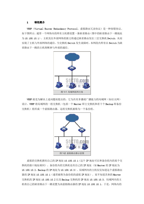
1 特性简介VRRP(Virtual Router Redundancy Protocol,虚拟路由冗余协议)是一种容错协议。
如下图所示,通常一个网络内的所有主机都设置一条缺省路由(图中的缺省路由下一跳地址为10.100.10.1),主机发往外部网络的报文将通过缺省路由发往三层交换机Switch,从而实现了主机与外部网络的通信。
当交换机Switch发生故障时,本网段内所有以Switch为缺省路由下一跳的主机将断掉与外部的通信。
VRRP就是为解决上述问题而提出的,它为具有多播或广播能力的局域网(如以太网)设计。
VRRP将局域网的一组交换机(包括一个Master即主交换机和若干个Backup即备份交换机)组织成一个虚拟路由器,这组交换机被称为一个备份组。
虚拟的交换机拥有自己的IP地址10.100.10.1(这个IP地址可以和备份组内的某个交换机的接口地址相同),备份组内的交换机也有自己的IP地址(如Master的IP地址为10.100.10.2,Backup的IP地址为10.100.10.3)。
局域网内的主机仅仅知道这个虚拟路由器的IP地址10.100.10.1(通常被称为备份组的虚拟IP地址),而不知道具体的Master 交换机的IP地址10.100.10.2以及Backup交换机的IP地址10.100.10.3。
局域网内的主机将自己的缺省路由下一跳设置为该虚拟路由器的IP地址10.100.10.1。
于是,网络内的主机就通过这个虚拟的交换机与其它网络进行通信。
当备份组内的Master交换机不能正常工作时,备份组内的其它Backup交换机将接替不能正常工作的Master交换机成为新的Master交换机,继续向网络内的主机提供路由服务,从而实现网络内的主机不间断地与外部网络进行通信。
2 适用版本软件版本:S9500-CMW310-R1628版本及以后升级版本(R2126及以上版本不支持)硬件版本:S9500交换机全系列硬件版本3 注意事项同一VRRP备份组多个备份的路由器之间,VRRP组握手时间必须一致,否则VRRP组状态会异常;同一VRRP备份组之间VRRP的工作方式必须相同,都为抢占模式,或者都为非抢占模式;必须在配置VRRP组之前启用vrrp ping-enable功能,否则无法ping通VRRP虚地址;VRRP监控端口只能监控VLAN接口地址,无法监控某个具体的端口;VRRP组的hello时间一般不建议修改;如果VRRP组数较多,可以考虑把各组的hello 时间分别设置成2、3、5、7等互质数,减少VRRP hello报文对CPU的冲击。
H3C配置MSTP

AP
SWD
DP RP/MP
Region 4
16
IST计算
SWA Region 1
Region 2 RP/MP SWB
DP
DP Region g 3 RP/MP SWC
DP
AP
SWD
DP RP/MP
Region 4
17
MSTI计算过程-Region1
MSTI 2 的拓扑 CIST Root
Region 3
8
MSTI和MSTI域根
MSTI 3的拓扑 g Root CIST Region
SWA SWB
MSTI 3 Region Root
SWC R i 3 Region
SWD
MSTI 5的拓扑
Region 3 VLAN 映射关系: VLAN 3 映射到Instance 3 VLAN 5 映射到Instance 5 其他VLAN映射到 IST
STP/RSTP交换机
Region 2
7
CST、IST、CIST、总根和域根
CIST
Region 2: VLAN mapping: VLAN 2 to Instance 2 VLAN 3 to Instance 3 Other VLANs to IST
CIST总根
Region 1: VLAN mapping: VLAN 2 to Instance 2 VLAN 4 to Instance 4 Other VLANs to IST
R i 1 Region
Host A VLAN2
Region 2 Region 4
Region 4: VLAN mapping: VLAN 4 to Instance 4 VLAN 5 to Instance 5 VLAN others th t to IST
H3C交换机名词解释
H3C 虚拟化技术IRF(Intelligent Resilient Framework)属于N:1整合型虚拟化技术范畴。
对于服务器或应用的虚拟化架构,IT行业相对比较熟悉:在服务器上采用虚拟化软件运行多台虚拟机(VM---Virtual Machine),以提升物理资源利用效率,可视为1:N的虚拟化;另一方面,将多台物理服务器整合起来,对外提供更为强大的处理性能(如负载均衡集群),可视为N:1的虚拟化。
对于基础网络来说,虚拟化技术也有相同的体现:在一套物理网络上采用VPN或VRF 技术划分出多个相互隔离的逻辑网络,是1:N的虚拟化;将多个物理网络设备整合成一台逻辑设备,简化网络架构,是N:1虚拟化。
H3C 虚拟化技术IRF(Intelligent Resilient Framework)属于N:1整合型虚拟化技术范畴。
MSTP(Multi-Service Transfer Platform)(基于SDH 的多业务传送平台)是指基于SDH 平台同时实现TDM、ATM、以太网等业务的接入、处理和传送,提供统一网管的多业务节点。
多生成树(MST)使用修正的快速生成树(RSTP)协议,叫做多生成树协议(MSTP)MSTP(Multiple Spanning Tree Protocol,多生成树协议)LACP,基于IEEE802.3ad标准的LACP(Link Aggregation Control Protocol,链路汇聚控制协议)是一种实现链路动态汇聚的协议。
LACP协议通过LACPDU(Link Aggregation Control Protocol Data Unit,链路汇聚控制协议数据单元)与对端交互信息。
启用某端口的LACP协议后,该端口将通过发送LACPDU向对端通告自己的系统优先级、系统MAC地址、端口优先级、端口号和操作Key。
对端接收到这些信息后,将这些信息与其它端口所保存的信息比较以选择能够汇聚的端口,从而双方可以对端口加入或退出某个动态汇聚组达成一致。
H3C VRRP+MSTP+链路聚合实战
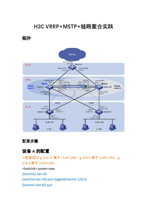
H3C VRRP+MSTP+链路聚合实践拓扑配置步骤设备A的配置#配置端口g 1/0/22属于VLAN 300、g 1/0/2属于VLAN 200、g 1/0/1属于VLAN 100。
<SwitchA> system-view[SwitchA] vlan30[SwitchA-vlan 30] port GigabitEthernet 1/0/22[SwitchA-vlan30] quit[SwitchA] vlan 100[SwitchA-vlan100] port GigabitEthernet 1/0/1[SwitchA-vlan100] quit[SwitchA] vlan 200[SwitchA-vlan200] port GigabitEthernet 1/0/2[SwitchA-vlan200] quit#创建二层聚合接口1。
[SwitchA] interface bridge-aggregation 1[SwitchA-Bridge-Aggregation1] quit#分别将端口GigabitEthernet 1/0/23和GigabitEthernet 1/0/24加入到聚合组1中。
[SwitchA] interface GigabitEthernet 1/0/23[SwitchA- GigabitEthernet 1/0/23] port link-aggregation group 1 [SwitchA-GigabitEthernet 1/0/23] quit[SwitchA] interface GigabitEthernet 1/0/24[SwitchA-GigabitEthernet 1/0/24] port link-aggregation group 1 [SwitchA-GigabitEthernet 1/0/24] quit#配置二层聚合接口1为Trunk端口,并允许VLAN 101和102的报文通过。
- 1、下载文档前请自行甄别文档内容的完整性,平台不提供额外的编辑、内容补充、找答案等附加服务。
- 2、"仅部分预览"的文档,不可在线预览部分如存在完整性等问题,可反馈申请退款(可完整预览的文档不适用该条件!)。
- 3、如文档侵犯您的权益,请联系客服反馈,我们会尽快为您处理(人工客服工作时间:9:00-18:30)。
杭州华三通信技术有限公司 版权所有,未经授权不得使用与传播
构建H3C高性能园区网络 1.0
引入
STP/RSTP都是单生成树协议 生成树协议如何实现负载分担?
课程目标
学习完本课程,您应该能够:
了解MSTP和RSTP/STP的不同之处 掌握MSTP的基本概念 掌握MSTP的工作原理 掌握MSTP的配置
Region 4 CIST 配置信息 MSTI 4配置信息 MSTI 5配置信息 SWC SWA
E1/0/1
SWB
E1/0/1
IST BPDU
15
CST计算
SWA
Region 1
Region 2 RP/MP SWB
DP
DP
Region 3
RP/MP SWC
DP
AP
SWD
DP RP/MP
21
MSTP计算结果及分析(续)
CIST总根
Region 2: VLAN mapping: VLAN 2 to Instance 2 VLAN 3 to Instance 3 VLAN others to IST Region 1: VLAN mapping: VLAN 2 to Instance 2 VLAN 4 to Instance 4 VLAN others to IST
CIST总根
Region 1: VLAN mapping: VLAN 2 to Instance 2 VLAN 4 to Instance 4 Other VLANs to IST
CIST域根
Region 1
CST IST
Region 2 Region 3
Region 4
Region 4: VLAN mapping: VLAN 4 to Instance 4 VLAN 5 to Instance 5 Other VLANs to IST Region 3: VLAN mapping: VLAN 3 to Instance 3 VLAN 5 to Instance 5 Other VLANs to IST
Region 1
Region 2
Region 3
Region 4
Region 4: VLAN mapping: VLAN 4 to Instance 4 VLAN 5 to Instance 5 VLAN others to IST Region 3: VLAN mapping: VLAN 3 to Instance 3 VLAN 5 to Instance 5 VLAN others to IST
Octet
2
1
1
1 8
4
8
2
MSTI配置信息
Parameter
MSTI Flag MSTI Region Root ID MSTI IRPC MSTI Bridge Priority MSTI Port Priority
2 2
2
Octet
1
8 4 1 1 1
2
1
}
MSTI Remaining Hops
22
MSTP和RSTP的互操作
RSTP桥将MSTP域看做一个桥ID为域根ID 的RSTP桥
域根
SWA BID=0.MAC A
BPDU
SWB BID=4096.MAC B
MSTP Region
RSTP桥
23
MSTP的P/A机制
上游桥发送的Proposal BPDU中,P标志 位和A标志位都置位
MSTI 5 Region Root
9
MSTP中的端口角色
Master端口
IST根桥在CIST上的根端口
域边界端口/Master端口
其他端口角色的定义和RSTP相同
SWA DP DP
DP
RP AP
SWB AP
RP SWC
DP DP Region 3
RP AP
DP SWD DP
下游收到P标志位和A标志位都置位的 Proposal BPDU,在将端口同步后会回应 Agreement BPDU,使得上游的指定端口 快速进入转发状态
SWA Proposal (P=1;A=1) SWB
Agreement(A=1)
目录
MSTP引入 MSTP基本概念 MSTP工作原理 MSTP配置
STP/RSTP的局限
所有VLAN共享一颗生成树 无法实现不同VLAN在多条Trunk链路上的负 载分担
SWA BID=0.MAC A SWA BID=0.MAC A
SWB BID=8192.MAC B
SWB BID=8192.MAC B
Region 4
16
IST计算
SWA Region 1
Region 2 RP/MP
SWB
DP
DP Region 3 RP/MP SWC
DP
AP
SWD
DP RP/MP
Region 4
17
MSTI计算过程-Region1
MSTI 2 的拓扑 CIST Root
其次比较CIST外部路径开销
再次比较CIST域根ID 再其次比较CIST内部路径开销
再其次比较CIST指定桥ID
再其次比较CIST指定端口ID 最后比较CIST接收端口ID
13
MSTI 的优先级向量
MSTI优先级向量={RRootID: IRPC: DesignateBridgeID: DesignatePortID:
Region 2: VLAN mapping: VLAN 4 to Instance 4 VLAN 5 to Instance 5
STP/RSTP交换机
Region 2
7
CST、IST、CIST、总根和域根
CIST
Region 2: VLAN mapping: VLAN 2 to Instance 2 VLAN 3 to Instance 3 Other VLANs to IST
}
MSTI 优先级向量
12
CIST的优先级向量
CIST优先级向量={RootID: ERPC: RRootID: IRPC: DesignateBridgeID: DesignatePortID: RcvPortID} 比较原则:最小最优
首先比较CIST总根ID
Region 1
Host A
VLAN2
Region 2
Region 3
Region 4
Region 4: VLAN mapping: VLAN 4 to Instance 4 VLAN 5 to Instance 5 VLAN others to IST
Host B VLAN2
Region 3: VLAN mapping: VLAN 3 to Instance 3 VLAN 5 to Instance 5 VLAN others to IST
Region 1
Host A
VLAN3
Region 2
Region 3
Region 4
Region 4: VLAN mapping: VLAN 4 to Instance 4 VLAN 5 to Instance 5 VLAN others to IST
Host B VLAN3
Region 3: VLAN mapping: VLAN 3 to Instance 3 VLAN 5 to Instance 5 VLAN others to IST
5
目录
MSTP引入 MSTP基本概念 MSTP工作原理 MSTP配置
MST域
MST域(MST Region):拥有相同MST配置标识的 网桥构成的集合
域名 修订级别 VLAN映射关系
Region 1
Region 1: VLAN mapping: VLAN 2 to Instance 2 VLAN 4 to Instance 4
20
MSTP计算结果及分析
CIST总根
Region 2: VLAN mapping: VLAN 2 to Instance 2 VLAN 3 to Instance 3 VLAN others to IST Region 1: VLAN mapping: VLAN 2 to Instance 2 VLAN 4 to Instance 4 VLAN others to IST
8
MSTI和MSTI域根
MSTI 3的拓扑
CIST Region Root
SWA SWB
MSTI 3 Region Root
SWC Region 3
SWD
MSTI 5的拓扑
Region 3 VLAN 映射关系: VLAN 3 映射到Instance 3 VLAN 5 映射到Instance 5 其他VLAN映射到 IST
VLAN1~VLAN100 VLAN1~VLAN50
VLAN51~VLAN100 VLAN1~VLAN100
SWC BID=32768.MAC C
均阻塞此链路
VLAN51~VLAN100 链路中断,无法通信
SWC BID=32768.MAC C
4
MSTP
MSTP(Multiple Spanning Tree,多生成树协议) 基于实例计算出多颗生成树,实例间实现负载分担
SWA BID=0.MAC A
实例1:VLAN1~VLAN50阻塞 实例2: VLAN51~VLAN100转发
