热熔胶封箱改造1讲义教材
热熔胶学习资料精简版

施胶时所需要的物性
• 施胶性 – 熔融粘度 – 软化点 – 开放时间 – 固化时间
• 热稳定性 • 模切性 • 成本
7
热熔胶的评价方法(1)
对制品所要求的物性
• 粘接力(剥离力) ・・・ 剥离强度测定、剥离界面评价 • 初粘性 ・・・环状初粘性、滚球初粘性 、指压 • 持粘力(蠕变性)・・・ SAFT、橡胶内聚力 • 耐热性、耐寒性 ・・・在环境试验室内的各种试验 • 色相 ・・・ 色差计、目视、Gardner对比 • 耐渗油性(标签) ・・・渗透加速试验
• 热稳定性 ・・・ 在熔融温度下确认粘度、软化点随时间的变化 • 模切性・・・用目视确认薄膜的伸长程度,用实际设备评价
等
2021/5/23
9
热熔胶的种类
热熔胶是以基础聚合物、增粘剂、粘度调整剂(软 化剂)、添加剂(抗氧化剂等)构成。按照基础聚合 物的种类分类。
–橡胶系 ・・・苯乙烯系弹性体,主要是粘合用的 –EVA系 ・・・ 最常用的粘剂,包装、装订 –烯烃系 ・・・ APAO,PE/PP用胶较多 –聚酯系・・・ 耐热、耐溶剂性胶,纤维、金属用 –聚酰胺系 ・・・耐热、耐溶剂性胶,制罐、电子配件 –氨基甲酸酯系 ・・・ 反应型HMA,木工、汽车配件
16
施胶机的设定条件与注意点
• 设定项目
• 熔融温度 ・・・ 超出推荐使用温度,会有发生问题的可能性 • 施胶头的温度 ・・・对基材的接合力、耐热性 • 泵的转足涂布量的熔融速度的最低温度。 ・HMA熔融需要时间,因此胶总要保持满的状态。 ・禁忌空加热。
• 卫生材料(尿不湿等) • 汽车内部装饰 • 电气
2021/5/23
粘合剂
– 标签 – 各种胶带 – 塑料袋封口
汉高热熔胶技术交流PPT幻灯片课件

膜封住瓶口,置入热风循环的恒温烘箱
在180ºC加热72小时后取出,观察老化
结果,检测粘度变化。
检测项目:
是否碳化及程度 是否结皮及程度 是否分层及程度 是否胶化及程度 是否凝胶及程度 老化后稀稠度的变化
热熔胶基础知识----性能及测试(3)
良好的热稳定性
RM Delivery
On Site RM Warehouse
Incoming Check
RM Pre-batch
External FG Warehouse
Finial Check
Process Control
KG
Filter
Packaging
Delivery to customers
RM Charging
过滤网
水胶(WBA)生产 目视
装量 外包装 工作指导书 计量
固含量 粘度 PH
外包装 数量 质量状况 外观 包装形态 数量 外观 包装形态 数量 客户名称
检验程序
仪器测量 计量
成品生产交接 程序
水基胶成品仓 库管理工作指 导书
目视 目视
发货工作指导 书
目视
记录资料 物料收货单
责任部门 物流部门
相关文件 PO
粘合剂,密封及表面处理
总部位于德国杜塞尔多夫
销售收入: 2010年150亿多欧元
2008年4月完成对国民淀粉化学公司粘合剂业务的收购
汉高中国
亚太总部& 研发中心:
中国上海浦东张江高科技园区
工业粘合剂工厂: 上海松江、上海南汇、广东虎门、广东
汕头,
Manufacturing Overview
包最新装技术手册

种类
PE淋膜 PP淋膜
特 性 概述
表面细致,有良好防水性,纸盒撕破会看见一层薄膜。当用 火点燃时,PE膜会比纸板先卷曲,烧焦后的味道类似蜡烛燃 烧。
表面光滑,比PE膜更硬更量,较难撕破,此PE较无延展性, 以火点燃时亦会卷曲,味道同PE,折过后有痕迹。
UV淋膜 光亮纸板表面纹路明显,耐高温200℃,故表面不易受损。
精选课件
1-2.热熔胶与传统胶有何不同?
热熔胶之优点
传统胶之优点
·100%固形物,无环保问题。
·不需干燥过程可缩短工作站流程。 ·固化速度快,生产效率高。 ·机械设备简单,维修容易。 ·无毒性,无刺激气味,无溶剂。 ·固体形状,易于搬运及储运。
·价格低廉。 ·接着力强。 ·耐溶剂,耐药品性高。 ·接着范围广。 ·接着后已定型,不易再弹开。 ·有良好之耐候性。
热熔胶之缺点
传统胶之缺点
·接着材质有限制。 ·耐溶剂,耐药品性。 ·需增添热熔胶机械设备,加热。 熔胶后才可使用。 ·接着后无法耐高温(80℃以上)。 ·操作温度过高胶质易产生黄变。
·具毒性,因含溶剂不符环保要求。 ·因需干燥设备,生产效率低。 ·仓储、运输、机械成本较高。 ·因溶剂挥发而黄变。 ·易燃烧,安全性低,储藏不易。 ·易受气候影响,冻结无法使用。
造将使接着更为困难,含泼水剂愈多愈难接着。泼水剂之等 级一般分为 R0、R2、R4R4R6R7R8R9R10 等,R10为最高等 级的泼水剂。 ③ 纸板之毛细孔结构亦会有影响,毛细孔愈小者愈难黏着。 ④ 表面光滑,较无纤维组织者,胶越不容易接着。
精选课件
精选课件
3-1-2.饼干或糖果盒纸板之表面处理:
?
4-3. 成果评估
热熔胶入门必备讲义

发展历史
☆1984年:美,反应型聚氨酯热熔胶,在汽车工业
广泛应用; ☆近十年来:日本需求增速10%/年 、美国13%/年; ☆1998年:某些发达国家需求量占合成胶粘剂市场 的20%;
☆2000年:全球热熔胶用量>120万吨;
☆新品种、新工艺不断出现。
特点
(1)胶接迅速; (2)不含溶剂; (3)对人体无害,运输、保管方便; (4)可反复熔化胶接,重复使用; (5)可胶接多种材料; (6)耐化学药品性强,电性能好; (7)光泽和光泽保持性良好,屏蔽性卓越;
——种类:
⊕SBS:苯乙烯-丁二烯-苯乙烯嵌段共聚物。溶解性 好,相容性好,加入树脂和增粘剂可降低其熔融 粘度,非常适合制备热熔胶、热熔压敏胶。
⊕SIS:苯乙烯-异戊二烯-苯乙烯嵌段共聚物。兼具
塑料的可溶性、热可塑性和硫化橡胶的韧性、弹 性,模量低、溶液粘度和熔融粘度小,加工性能 良好,内聚力很好,粘附性能优良,制作热熔压 敏胶的主体材料。 ——应用:SBS和SIS热熔胶及其加氢产物用于制作 各种胶粘带和标签用胶,粘接金属和非金属,妇 女用品和尿布制作中应用很多。
辆部件等。
(3)聚酯类热熔胶粘剂
——概念:聚酯(PET)是主链中含有酯基(-COO-)
的聚合物的总称,分不饱和聚酯和热可塑性聚酯
(线性饱和聚酯,由二元酸和二元醇或醇酸缩聚
而成);作为热熔胶需用可塑性聚酯;
——特点:优异的电绝缘性;较好粘接强度;耐冲
击性、耐水、耐热、耐寒、耐介质及弹性都较好;
可粘接多种材料;熔体粘度高; ——应用:服装、电器、制鞋、建筑等行业。
高档热熔胶
聚酯型热熔胶
聚酰胺型热熔胶
(5)聚氨酯类热熔胶粘剂
——概念:聚氨酯是聚氨基甲酸酯的简称,是指分 子主链上含有许多重复的氨基甲酸酯(-OOCNH-) 基团的聚合物,由多异氰酸酯和聚合物多元醇加 聚而成。
塑封基础知识培训课件(PPT 38张)

TIME(DAY)
EME存储寿命随着存储温度的提高显著短缩。
成型条件 Molding Conditions
a.锭粒预热Preheating of Pellet
●预热前的准备Preparation for stable preheating
Sp =π(*D回p/2)温2 充分,赶走湿气Stabilization of compound temperature and humidity
UNIFORM HEATING 固化温度和时间CURE TEMP. AND TIME 后固化时间要在烘箱达到合适的温度后开始计时
CURE TIME SHOULD BE COUNTED AFTER REACHING PROPER
TEMP. LEVEL
Temp(℃) 180 170
SPEC. 175±5℃
90 80 70 60 50
155
165
175
185
195
MOLDING TEMD7
4-成型 Molding
4.1.黑胶准备 Compound Preparation
冷冻保存 (10℃) Cold Storage (10℃)
回温 Stabilizing (20℃-30℃,50-70%RH )
d.转进速度/时间TRANSFER SPEED/TIME
转进速度是通过转进距离除于转进时间得到的
TR. SPEED IS CALCULATED WITH TR. DISTANCE AND TR.TIME
TR. SPEED (CM/SEC)= TRD. ISTAN(CCEM)
TR. DISTANCE (L)
ADJUST PELLET WEIGHT TO GET PROPER CULL THICKNESS 太厚TOO THICK But complexed runner and cavity structure will make pressure loss. (不完全充填INCOMPLETE FILL) 1-Raw Material Support for EME In CCP(蓝色为CCP自产) 3-在充填过程中,EME黏度行为曲线
热熔胶入门必备

胶粘剂溢出过多
总结词
胶粘剂溢出过多不仅浪费胶粘剂,还会影响粘接效果和 美观度。
详细描述
要解决这一问题,可以调整胶粘剂的加热温度和出胶口 的大小,控制胶粘剂的流量。同时,在使用过程中注意 保持操作台面的整洁,及时清理溢出的胶粘剂。此外, 根据需要选择不同规格和形状的热熔胶棒,以减少胶粘 剂的浪费。
感谢您的观看
热熔胶入门必备
目录
CONTENTS
• 热熔胶简介 • 热熔胶的制造工艺 • 热熔胶的使用方法 • 热熔胶的优点与缺点 • 热熔胶的发展趋势与未来展望 • 热熔胶的常见问题与解决方案
01 热熔胶简介
定义与特性
定义
热熔胶是一种在加热后会熔化成液态, 并能迅速粘附在各种材料上的粘合剂。
特性
具有快速粘合、耐候性强、粘合力强、 无毒无味等优点。
原材料的质量控制可以确 保原材料的质量稳定,从 而保证热熔胶的质量和性 能。
成品的检验和测试可以对 热熔胶的性能进行全面的 评估,确保其符合要求和 标准。
生产过程中的监控可以及 时发现和解决生产过程中 的问题,避免产生不合格 品。
03 热熔胶的使用方法
热熔胶枪的选择与使用
热熔胶枪的选择
选择质量可靠、品牌信誉好的热熔胶枪,以确保使用过程中的安全和稳定性。
如何扬长避短
合理选择
根据使用环境和需求选择合适的热熔 胶型号和品牌。
正确使用
按照说明书正确使用热熔胶,避免过 度加热或冷却。
定期检查
定期检查热熔胶的状态,发现异常及 时处理。
维护保养
对粘合部位进行定期保养,保持清洁 干燥,以提高粘合效果和使用寿命。
05 热熔胶的发展趋势与未来 展望
环保与可持续发展
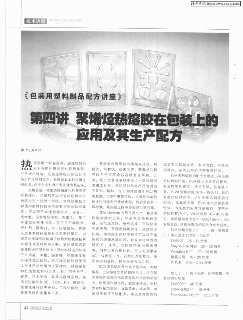
《包装用塑料制品配方讲座》:第四讲 聚烯烃热熔胶在包装上的应用及其生产配方
改性 树 脂 石蜡 抗氧剂
2 5~6 0份 重
0~3 0份 重 O 0 ~02 . 5 .5份 重
配 方 (六 ) 使 用 国 外 材 料 生 产 的 :
压 敏 胶
EV A 5 01 EV A 6 05 1 重 5份 3 0份 重 3 7份 重
Ey 公司 生产 的产 品 牌 号 tl
是 : 磷 酸 三 甲 酚 酯 、 邻 苯 二 甲 二 异 辛 酯 、 三 乙 二 醇 二 已酸 酯 等 。]
抗氧剂
0 5份 重 .
例 掺 混物 。 配 方 (五 ) 用 于 压 敏 包 装 胶 带 用 :
配方 ( ) 七 :使 用 国 外 材 料 生 产 的
E A 热熔 不干 胶 V
蕉 熔 脏 是 一 却 加 热 熔 融 液 化 后 具 有 良 了 复合 例 如 P T 热 熔 黢 膜 片 / L 热 E / A/ 碲.当V A台 最 达 到 1 % ~ 8 时 .E A 8 2% v
好粘 接性 .冷却 后可 以把 饭楚 赔物牢 牢 熔 胶 膜 片 / P C P膜 等 结构 。 也 可 把 燕 雌 睃 有 最 佳 的 粘 结 性 VA 含 量 遮 到 或 超 过 地 结 台 在 一 起 的 一 种 睦 这 种 睃 随 配 方 粉 末 均 匀涂 布 于 基 材 表 面 然后 复合 另 ~ 40% .结 晶 度 为 零 .EVA 威 为 热 塑 性 弹
有 那 么 好 的 技 术 水 平 ,如 果 是 这 样 ,那 你 可 以 从 自身 入 手 , 子 。 企 业 相 互 间 的 协 作 将 彼 此 的共 性 问题 剥 离 出 来 ,实 现 分 工 的细 化 ,从而 为企业 创造 “ 自身 增 值 ” 北 京 顶 佳 世 纪 印 。
热熔胶缝合设备维修和维护套件说明书
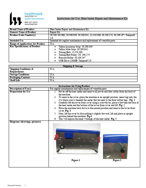
Instructions for Use: Heat Sealer Repair and Maintenance Kit Brand Name of Product Heat Sealer Repair and Maintenance KitGeneric Name of Product Repair KitProduct Code Number(s)30.100.561-RK, 30.200.039, 30.200.041, 12.210.300, 30.100.174, 30.100.197, Tempsoft2.0.Intended Use Intended for regular maintenance and replacement of wearable parts.Range of Applications for Product N/AKey Specifications of Product●Teflon Insulation Strip- 30.200.039●Teflon Slide Strip- 30.200.041●Timing Belt- 12.210.300●Timing Belt Pulley- 30. 100.174●Pressure Roller- 30.100.197●USB Drive 128MB- Tempsoft 2.06.This will expose the inner workings of the heat sealer. Fig. 5Figure 1 Figure 1Figure 2Figure 3 Figure 4Figure 5Replacing the Teflon Slide Strip on the Guide Bars1.With the cover already removed, remove the top transport belt clockwise from thetop right pulley. Fig. 1Figure 12.Lift the aluminum guidance bar slightly to easily remove the transport belt. Fig. 2Figure 23.Remove the screw for the right upper element support with an “L” wrench turningcounterclockwise. Fig. 3Figure 34.Remove the element support and watch for the small spring inside the aluminumguiding bar. Fig.4Figure 4ing the “L” wrench, unscrew two screws to release the left element support. Fig.5Figure 56.Release the left element support and watch for the spring. Fig. 6Figure 67.Release the lower aluminum feed through guidance bar. Fig. 7Figure 7ing a Phillips head screwdriver, unscrew the earth wire from the heating bar andpull out the heating element from the heating bar. Fig. 8, 8AFigure 8Figure 8A9.Next, release the connection from the clickson. Fig. 9Figure 910.Release the wires for the thermocouple. Fig. 10Figure 10ing the “L” wrench, remove the screw from the lower heating bar. Watch for theTeflon insulation rings when removing the heating bar. Fig. 11, 11AFigure 11Figure 11A12.Remove the heating element. Loosen the screws on the Teflon and heating bar andremove the Teflon strip from the heating bar. Fig. 12Figure 1213.Remove the glue residue with a sharp knife. Do not damage the heating bar as thisis soft messing. Fig. 13Figure 1314.With Scotch Brite, clean any residue away. Fig. 14Figure 1415.Clean the heating bar with a non-linting cloth with dissolvent to remove anyremaining glue residue. Fig. 15Figure 1516.Place a new Teflon strip onto the heating bar by separating the Teflon strip andglue strip away from each other.17.Place the new Teflon strip onto the heating bar by placing the wrap on the backside of the heating bar, wrap around and place along the bar with the remainingstrip wrapped around the other end of the heating bar. Make sure there are no air bubbles present under the Teflon strip. Fig. 16, 16AFigure 16Figure 16A18.Make a small hole at the spot where the screw is inserted. Fig. 17Figure 1719.The Teflon strip will have a small amount of hangover on the heating bar. Removewith a very sharp knife and keep the blade flat against the heating bar as it cutsaway the remaining material. Fig. 18, 18AFigure 18Figure 18A20.Cut out a round hole for the heating element to be placed back into the heating bar.Fig. 19Figure 19Figure 1921.Clean the heating element before replacing back into the heating bar with a clothand ROCOL heating paste. Fig. 20Figure 2022.With a gloved hand, apply ROCOL heating paste to the heating element. With onefinger, spread the paste evenly all over the heating element before inserting backinto the heating bar. Fig. 21Figure 2123.Insert the heating element into the heating bar. As the heating element is insertedinto the bar, residual paste will accumulate at the top of the hole on the heating bar.Fig. 22, 22AFigure 22Figure 22A24.Wipe away the remaining paste making sure it is completely clean. Fig. 23, 23AFigure 2325.Place the heating element into the heating bar. Fig. 24Figure 2426.Refit the earth screw and the screws back onto the heating bar and the wires so theclickson can be refitted again (the wires do not have any polarity). Fig. 25, 26Figure 25Figure 2627. Reattach the thermocouple. Fig. 27Figure 2728.Reattach the screw and the Teflon ring using the “L” wrench. Fig. 28 Figure 2829.Screw the aluminum feed through the bars. Fig. 29Figure 2930.Screw in the element support again. Be sure to put the timing belts on so thealuminum guidance bars are fixated. Fig. 30Figure 3031.Tighten the screws with the “L” wrench to the heating bars to where they can movefreely. Fig. 31Figure 3132.Place the transport belt and timing belt pulley back on.33.Heat sealer is ready for use again. Fig. 32Figure 3234.Lower the top cover of the heat sealer back down.35.Place the lower front cover back into place on the heat sealer.36.Place the heat sealer in an upright position, insert and tighten the two black screwsinto the holes next to the front rubber legs.37.Place heat sealer back down to normal position.38.Plug in and power on heat sealer.Replacing the Transport Belts1.Remove the cover from the heat sealer. Fig. 1Figure 12.Remove the transport belt clockwise from the top right pulley. Fig. 2Figure 23.Lift the aluminum guidance bar slightly to easily remove the transport belt. Fig. 3Figure 34.Replace with the new belts one at a time.5.Lift the aluminum guidance bar slightly then insert the new transport belt with theteeth on the belt facing down, make sure to place the belt teeth into the grooveopenings of the pulley.6.Then pull the belt to the opposite end and place the belt around the pulley with eachof the belt teeth into the groove openings of the pulley.Replacing the Pulley1.Remove the cover. Fig. 1Figure 12.Remove the transport belt from the pulley. Fig. 2Figure 23.Lift the aluminum guidance bar slightly to easily remove the transport belt. Fig. 3Figure 34.Remove the screw inside the pulley. Fig. 4Figure 45.If the pulley cannot be freed by hand, use a pulley puller to remove. Fig. 5Figure 56.Once removed, replace with a new pulley. Tighten the screw inside the pulley.7.Place the transport belts back onto the pulleys.8.Lower the top cover of the heat sealer back down.9.Place the lower front cover back into place on the heat sealer.10.Place the heat sealer in an upright position, insert and tighten the two black screwsinto the holes next to the front rubber legs.11.Place the heat sealer back to normal position.12.Plug in and power on the heat sealer.Replacing the ThermocoupleNote: A thermocouple could be replaced when packaging materials melt when sealing at the temperature as recommended by the pouch manufacturer.●To check if the thermocouple is indicating wrong values, measure the temperatureat the spot where the thermocouple is located. After this, the temperature on themeasuring device and the temperature on the display need to be checked.●If the measuring device indicates a temperature which is too low and the machineneeds a lot of time to heat up (or does not reach the temperature after a long time),it could mean that the lower heating element is broken. In this case, one wouldalso see a “Temp. Alarm” in the display.1.Release the screws which hold the thermocouple wires. Fig. 1Figure 12.Put a screwdriver through the hole in the mounting plate to reach the screw of thethermocouple and remove the screw. Fig. 2Figure 23.Remove the screw on the thermocouple. Fig. 3Figure 34.Grease the new thermocouple with ROCOL paste and place the screw back intothe thermocouple and tighten. Fig. 4Figure 45.Fit the new thermocouple and make sure it is fitted correctly. Fig. 5Figure 56.The thermocouple wires can be refitted as shown below. Fig. 6Figure 67.Lower the top cover of the heat sealer back down.8.Place the lower front cover back onto the heat sealer.9.Place the heat sealer in an upright position, insert and tighten the two black screwsinto the holes next to the front rubber legs.10.Place the heat sealer back down to normal position.11.Plug in and power on the heat sealer.Calibrating the Temperature for the F108TX/F108TX-P PROTECNote: Calibrating the temperature is meant to tell the PCB board acutely what 180ºC input by the thermocouple connector is.●The calibration of the temperature should be performed to 1% precise of the settemperature. This means that when calibrating at 180ºC, the tolerance may be 1,8ºC which will result in +/- 2ºC as the display only indicated full figures.●When connecting a thermocouple simulation device, a temperature reading in thedisplay between 178ºC and 182ºC when calibrating at 180ºC is acceptable.1.Make sure the power supply cord is taken out of the back of the machine to preventany electrical shocks.2.Open the cover as indicated in steps 1-5 in Diagrams (drawing and pictures).3.Disconnect the connector for the heater and clickson as show below. Fig. 1Figure 14.Place the test jumper on the test connector on the PCB board. Fig. 2Figure 25.The F108 series are equipped with one thermocouple connection point, TK1 whichis located on the PCB board.6.Connect the thermocouple simulation device to TK1. TK1 is used to control thetemperature control on the PCB board.7.Connect the thermocouple simulation device and set it to Thermocouple Type J andat 130ºC. Switch on the heat sealer and wait for 10 seconds. Fig. 3Figure 38.Check the temperature indicated in the display of the heat sealer.9.Check if the temp at “Temp1” is 130ºC. Fig. 4Figure 410. If not, use until the temperature of 130ºC has been reached.11.When the correct temperature has been reached on the display, you can fix thissetting by pressing .12.The temperature indicated at “Print” should be 24ºC.13. If a different temperature is indicated, you can adjust it to 24ºC by using the.14.However, it can occur that the temperature at Temp 1 slightly changes.15.If the temperature is between 128ºC and 132ºC, no further action needs to be taken.16.If the temperature is outside of this range, please contact Famos bv.17.Next, set the temperature simulation device at 180ºC and check the temperatureindicated in the display of the heat sealer. Fig. 5Figure 518.Check that the temp at “Temp 1” is 180ºC.19.If not, please use until the temperature of 180ºC has been reached.20.When the correct temperature has been reached on the display, you can fix thissetting by pressing .21.The temperature indicated at “Print” should be 24ºC.22.If a different temperature is indicated, you can adjust it to 24ºC by using the.23.However, it can occur that the temperature at Temp 1 slightly changes.24.If the temperature is between 178ºC and 182ºC, no further action needs to be taken.25.If the temperature is outside of this range, contact Famos bv.Only use the buttons as mentioned above and no other buttons on the keyboard.26.Switch off the heat sealer.27.Disconnect the thermocouple simulation device from TK1.28.Remove the test jumper from the TEST connector on the PCB board.29.Reconnect the connector for the heater and clickson.30.Lower the top cover of the heat sealer back down.31.Place the lower front cover back onto the heat sealer.32.Place the heat sealer in an upright position, insert and tighten the two black screwsinto the holes next to the front rubber legs.33.Place the heat sealer back to normal position.34.Plug in and power on the heat sealer.Calibrating the Pressure for the F108TX/F108-P/USB PROTECNote: Calibrating the pressure is meant to tell the PCB board acutely what weight on the load cell should result in a displayed pressure on the display of the heat sealer.●The adjusting of the force should be performed to +5 precise of the applied weight.When calibrating at 100 Newton, the tolerance may be +5 Newton. When puttingthe weight on the load cell, a force of 100-105 should be displayed on the display.If this is the case, no further adjustments need to be made.●With Tyvek pressure rollers, the set range reduce slightly when the machine isbeing left alone for a while.1.Place test jumper on the TEST connector on the PCB board. Fig. 1For models with a USB module, please make sure to remove the USB cable from the PCB board first. Otherwise, the calibration procedure will not work.Figure 12.The display shown is after putting the test jumper on the PCB board. Fig. 2Figure 2(The values on the display will look different.)3.Press the ON button on the keyboard to change to the following display which isneeded to check and adjust the pressure. Fig. 3Figure 3(The values on the display will look different.)4.When a seal is made, the force should increase by 5-7 Newtons depending on thethickness of the packaging material. This can be checked by the settings of themachine.5.When the value behind “force” would be lower than 95 Newton, adjust by turningthe aluminum grooved screw clockwise to increase the pressure andcounterclockwise to decrease the pressure. Fig. 4Figure 46.After the pressure has been set to approximately 100 Newton, press the red reversebutton to see the deviation in the pressure behind the “FORCE” on the display.7.After adjusting the pressure, make sure to secure the screw again by fixing thesmall nut on the top of the aluminum grooved screw. Fig. 5Figure 58.When a new PCB board or load cell is installed, place the test jumper on the TESTconnector and add the extra weight on top of the load cell. Fig. 6, 7Dismantle the pressure mechanism for the load cell by taking out the screw that ison top.Figure 6 Figure 79.Next, go to the pressure menu. The values on the display will look different. (i.e.“FORCE: ON and “FORCE 20N”). Fig. 8Figure 810.Press + or – Count until you see “FORCE: 100N” (The “FORCE 0” will runrandom for 0-90).11.Now that the settings are correct, make test seals to see if the pressure will increase.12.Remove the extra weight from the load cell.13.Mantle the pressure mechanism for the load cell by placing the screw back in andtighten.14.Remove the test jumper from the TEST connector.15.Lower the top cover of the heat sealer back down.16.Place the lower front cover back onto the heat sealer.17.Place the machine in an upright position, place and tighten the two black screwsinto the holes next to the front rubber legs.18.Place the machine back to normal position.19.Plug in and power the machine on.20.However, in the case of “FORCE: 100N” and if “FORCE 0” is in the range of 90-100, this means that the load cell is defective. In this case, the difference in valueis too small.Interpretation of Test Results N/A Contraindications of Test Results N/A Documentation N/A Special Warnings and Cautions N/A Disposal N/A。
热熔胶学习资料精简版ppt

热熔胶学习资料精简版ppt
热熔胶是一种常见的粘合剂,也被称为热熔胶棒或热熔胶枪。
它是一
种固态的胶,通过加热后变为液态,然后在固化过程中形成强大的粘合力。
热熔胶具有许多优点,如易于使用、快速干燥、粘接力强等,所以在许多
行业被广泛使用。
热熔胶的学习资料应该从以下几个方面进行讲解:
1.热熔胶的基本介绍:包括热熔胶的组成成分、制备方式、物理特性
等基础知识。
可以介绍热熔胶的主要原料、制备方法、固化方式等。
2.热熔胶的应用领域:介绍热熔胶在不同领域的应用,如家具制造、
包装行业、电子产品、纺织品等。
可以具体介绍一些实际案例,展示热熔
胶的应用价值和优势。
3.热熔胶的工作原理:详细介绍热熔胶在加热后的变化过程,包括热
熔胶的熔化温度、液态粘度、固化时间等。
可以从物理和化学角度解释,
让读者了解热熔胶的工作原理。
4.热熔胶的使用方法:介绍热熔胶的使用步骤,如如何正确使用热熔
胶枪、如何选择合适的胶棒、如何粘接不同材料等。
可以给出一些实际的
技巧和注意事项。
5.热熔胶的优缺点:客观地介绍热熔胶的优点和不足之处,如粘接力
不够强、耐高温能力较差等。
可以与其他粘合剂进行比较,让读者明确热
熔胶适用的场景和限制。
6.热熔胶的市场前景:介绍热熔胶在市场中的发展前景和趋势,包括市场规模、行业应用趋势等。
可以借助统计数据和预测分析,展示热熔胶在未来的市场潜力。
热熔封胶机教学设计方案
一、教学背景随着我国制造业的快速发展,热熔封胶技术在产品包装、电子、汽车等领域得到了广泛应用。
热熔封胶机作为实现热熔封胶技术的重要设备,其操作技能和维修保养已成为企业员工必备的职业技能。
为了培养具备热熔封胶机操作、维护与维修能力的技术人才,特制定本教学设计方案。
二、教学目标1. 知识目标:使学生掌握热熔封胶机的基本结构、工作原理、操作流程及维护保养知识。
2. 技能目标:使学生能够熟练操作热熔封胶机,进行产品封胶、故障排查与维修。
3. 素质目标:培养学生的团队合作意识、创新精神和实际操作能力。
三、教学内容1. 热熔封胶机概述(1)热熔封胶机的分类与特点(2)热熔封胶机的应用领域2. 热熔封胶机结构及工作原理(1)热熔封胶机的组成部分(2)热熔封胶机的工作原理3. 热熔封胶机操作与维护(1)热熔封胶机的操作流程(2)热熔封胶机的维护保养4. 热熔封胶机故障分析与排除(1)常见故障及原因分析(2)故障排除方法5. 实践操作(1)产品封胶操作(2)故障排查与维修四、教学方法1. 讲授法:教师讲解热熔封胶机的基本知识、操作流程、维护保养及故障排除方法。
2. 演示法:教师现场演示热熔封胶机的操作、维护保养及故障排除过程。
3. 实践操作法:学生分组进行实际操作,教师巡回指导。
4. 案例分析法:分析实际生产中热熔封胶机故障案例,提高学生的故障排查与维修能力。
五、教学评价1. 课堂表现:考察学生对热熔封胶机知识的掌握程度,包括提问、回答问题、课堂讨论等。
2. 实践操作:考察学生实际操作能力,包括产品封胶、故障排查与维修等。
3. 考试:进行书面考试,检验学生对热熔封胶机知识的掌握程度。
4. 反馈:收集学生对教学内容的意见和建议,不断优化教学方案。
六、教学进度安排1. 第一周:热熔封胶机概述、分类与特点、应用领域2. 第二周:热熔封胶机结构及工作原理3. 第三周:热熔封胶机操作与维护4. 第四周:热熔封胶机故障分析与排除5. 第五周:实践操作6. 第六周:复习、总结、考试七、教学资源1. 教材:《热熔封胶机操作与维护》2. 教学课件3. 实际热熔封胶机设备4. 网络资源:相关技术论坛、视频教程等八、教学实施1. 教师准备:提前备课,准备好教学课件、教材、教学设备等。
热熔胶组装教学设计方案
一、教学目标1. 知识与技能:了解热熔胶的种类、特性及应用领域,掌握热熔胶组装的基本原理和操作步骤。
2. 过程与方法:通过实际操作,培养学生动手能力、团队协作能力和问题解决能力。
3. 情感态度与价值观:激发学生对科技创新的兴趣,培养学生的环保意识,提高学生的社会责任感。
二、教学对象初中、高中学生,具备一定的动手能力,对科技创新有一定兴趣。
三、教学时间2课时四、教学资源1. 热熔胶:不同型号的热熔胶,如EVA、PE等。
2. 热熔胶枪:不同功率的热熔胶枪。
3. 组装材料:塑料、纸板、金属等。
4. 辅助工具:剪刀、尺子、镊子等。
5. 教学课件、视频等。
五、教学过程1. 导入新课(1)展示热熔胶在不同领域的应用案例,如包装、电子、汽车等。
(2)提问:热熔胶是如何组装的?有哪些优点?2. 知识讲解(1)介绍热熔胶的种类、特性及应用领域。
(2)讲解热熔胶组装的基本原理,如热熔胶的加热、固化过程。
(3)演示热熔胶枪的使用方法。
3. 实践操作(1)分组:将学生分成若干小组,每组4-6人。
(2)分配任务:每组选择一种组装材料,设计一个简单的组装作品。
(3)指导:教师巡回指导,解答学生在操作过程中遇到的问题。
(4)讨论:各小组分享组装心得,交流经验。
4. 作品展示与评价(1)各小组展示作品,介绍设计思路和制作过程。
(2)学生互评,教师点评。
(3)评选优秀作品,颁发奖品。
5. 总结与反思(1)总结本次课程的主要内容,强调热熔胶组装的技巧和注意事项。
(2)引导学生思考:热熔胶在生活中的应用有哪些?如何提高热熔胶组装的质量?六、教学评价1. 过程评价:观察学生在操作过程中的表现,如动手能力、团队协作能力、问题解决能力等。
2. 作品评价:评价作品的创新性、实用性、美观性等。
3. 问卷调查:了解学生对本次课程的评价和建议。
通过本次教学,使学生掌握热熔胶组装的基本技能,提高学生的科技创新能力和环保意识。
热熔胶包覆工艺培训资料(1)
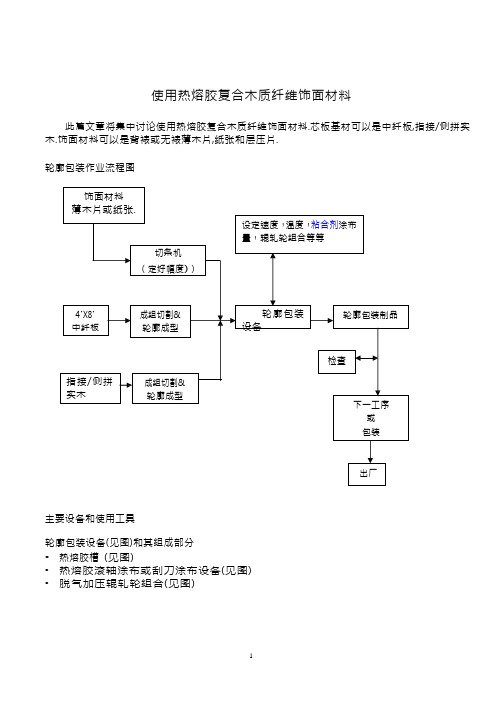
使用热熔胶复合木质纤维饰面材料此篇文章将集中讨论使用热熔胶复合木质纤维饰面材料.芯板基材可以是中纤板,指接/侧拼实木.饰面材料可以是背裱或无裱薄木片,纸张和层压片.轮廓包装作业流程图主要设备和使用工具轮廓包装设备(见图)和其组成部分•热熔胶槽(见图)•热熔胶滚轴涂布或刮刀涂布设备(见图)•脱气加压辊轧轮组合(见图)西班牙BARBERAN RP-30 型号轮廓包装设备西班牙BARBERAN ST 011 热熔胶槽滚轴涂布设备脱气加压辊轧轮组合(西班牙BARBERAN 提供图片)热熔较固化粘合机制热熔胶在室温下呈固体状态. 加热后将转化为熔融状态. 进一步提高温度至140°C - 210°C 后热熔胶将完全呈液体状态. 当液态热熔胶降低温度时, 将会引起固化作用. 这个过程是可回逆的. (见下图)在轮廓包装复合过程,呈液态热熔胶将在涂布设备里头涂布在饰面材料背面。
在湿润过程中液态热熔胶将渗透进入饰面材料结构里头。
热量将被转移至饰面材料或空气中,在涂布液态热熔胶的有效结合时间内,加压辊轧轮的压力将会使液态热熔胶湿润并且渗透进入基材微孔组织内,进一步的冷却将使热熔胶固化形成结合力。
适合纸张粘合. 选择.•如果使用薄木片或装饰片材料,一般都使用偏高粘度值的热熔胶.其他的热熔胶求特质如:高结合力,足够有效结合时间和足够的耐热性能.•如果使用纸张,一般都使用偏低粘度值热熔胶.其他的热熔胶要求特质如:平整涂布,高结合力,足够有效结合时间和足够的耐热性能是必要的热熔胶涂布•涂布过程一定要流畅,连贯性。
•根据粘合剂供应商的建议使用涂布量.•长时间的滞留会使热熔胶产生炭化现象,致涂布工艺恶化.因此,在长时间停机情况下,将热熔胶槽,涂布设备建议操作温度降低 20 -30°C.•生产复杂的轮廓形状芯材时,降低材料输送速度.正确的速度将依使用设备和热熔胶种类而定.•在每分钟 15 –25 米材料输送速度,170 - 220 温度下, 热熔胶涂布量: 薄木片/装饰片:120-180 gsm. 装饰纸张: 70–90gsm.热熔胶的一些特质影响粘合质素的因素使用多种类的饰面材料时,请详细的检讨以下的操作因素:热熔胶操作温度, 涂布量及有效结合时间(open time)正常操作时,如有发现不良粘合问题,首先检查热熔胶操作温度及涂布量. 正常操作温度应该是在 180 - 200°C. 正常热熔胶涂布量为每平方米 70 –150 克依材料而定.一般偏高的操作温度将引起偏低的粘度值;这将引起偏低的涂布量;同时提高有效结合时间和固化时间.如果使用温度超过建议使用温度,将会产生炭化现象同时改变并恶化热熔胶特质.偏低的的操作温度将引起偏高的粘度值;这将引起偏高的涂布量. 多余的热熔胶将会挤出污染设备;有可能引起设备停顿现象.如果需要复合复杂轮廓,这需要比较长的有效结合时间.还没复合前;使用热风器吹向热熔胶涂层将会延长热熔胶涂层的有效结合时间并且符合设备要求的有效结合时间.建议根据粘合剂供应商的建议操作方法并且选择正确的粘合剂用于轮廓包装产品.复合材料温度在四季分明的国度如中国,冬天时车间里头的温度可以非常低的.一般在冬天时制成品的次品/ 废品率非常的高.这是因为在低于20°C 室温时,热熔胶的涂布量和有效结合时间在此低室温下会改变.在具有空调的车间和没复合前使用热风器烘热热熔胶涂层可以提高复合材料的结合力和成品率.芯板输送速度和加压辊轧轮压力设备的输送速度将结定”设备”所需要的有效结合时间.热熔胶涂布量和温度决定了粘合剂有效结合时间,一般这个时间必须长于”设备”的有效结合时间.这就是说更快的设备输送速度对于提高成品率是有帮助的.没复合前,热风器的使用对于延长粘合剂有效结合时间也是有帮助的.加压辊轧轮的压力将提高热熔胶对于材料的湿润和渗透性以提高产生结合力.所以适当的压力将对于生产良好轮廓包装产品是有需要的.芯板和薄木片的含水率如果薄木片含水率低于 8%,在轮廓包装过程中后;薄木片表面有可能产生丝裂现象甚至于剥离.如果薄木片和/或芯板含水率高于 12%,轮廓包装过程后;在覆盖材料和芯板之间会产生一层水汽. 这将会大大的降低形成结合力甚至剥离现象.薄木片的种类不同的树种都具有它独特特质.相对那些高内应力少毛孔的树种;比较低内应力多毛孔树种是容易处理粘合的.在涂布过程中,有些树种倾向吸收多余的热熔胶,这将会产生丝裂现象. 使用适当的树种和热熔胶涂布量将决定轮廓包装制品的美观质量.如要进一步降低丝裂现象;使用有背裱的薄木片将会解决之前所面对的丝裂现象.如果因为成本原因而使用无裱薄木片,没进行轮廓包装前,喷涂一些水汽在薄木片表面上将加强成品的美观程度;但是这需要仔细准确的喷涂水分分量.讨论使用热熔胶生产轮廓包装产品牵涉到不同的因素条件如: 饰面材料和芯材, 轮廓包装设备种类和维修,良好的生产管理流程;最后使用正确良好的热熔胶粘合剂.生产者应该记录并且保留所有批号的生产条件.这些资料将对将来改进和设定标准作业流程有所帮助.。
- 1、下载文档前请自行甄别文档内容的完整性,平台不提供额外的编辑、内容补充、找答案等附加服务。
- 2、"仅部分预览"的文档,不可在线预览部分如存在完整性等问题,可反馈申请退款(可完整预览的文档不适用该条件!)。
- 3、如文档侵犯您的权益,请联系客服反馈,我们会尽快为您处理(人工客服工作时间:9:00-18:30)。
2020/8/4
选题理由
客观存在 导致结果 公司要求 最终结果
2020/8/4
热熔胶封好后出现开底现象 热熔胶封好底后需要用胶带二次封
底,导致加工成本增加 降低加工成本,提高产品封箱质量
省去热熔胶的消耗,降低加工成本。
2020/8/4
根据调查结果,我们将小组活动目标定 为把热熔胶的使用量降低到最低1g/个
环
2020/8/4
机
开箱机设备调整 不正常
底部开箱较多
热熔胶感应器不停 的喷 感应器坏
喷射泵坏
人
热 热熔胶感应器调
节位置不妥
熔 未正确调整感
应器位置
胶
胶
带
双
重
工艺流程不合理
封
箱 双重封箱造成浪费
法
2020/8/4
2020/8/4
制定对策 :
1、纸箱封底工艺流程图(改造前工艺)
纸箱
热熔胶
装箱
底部封箱 仓库
目标值确定依据
⑴ 小组成员具有操作经验丰富的 操作班长,胶带封箱技术较为成熟, 又有工艺技术、装备、生产管理人员 的大力协助,为小组有效的活动提供 了可靠保证。
2020/8/4
2g/个
1g/个
每个纸箱消耗的热熔胶重量
因果分析图
料
热熔胶质量不达标 封箱质量不 好开裂
设备只提供热熔封箱 设备本身消 耗热熔胶
2020/8/4
1、将改造的措施和生产数据进行统计. 2、继续细化车间生产工艺. 3、坚持对改造设备的数据进行跟踪监测,并根 据效果不断的进行调整.
2020/8/4
在不影响产品质量的基础上, 进一步探讨车间操作的工艺参 数和操作方法,提高产品外观 包装质量 。
2020/8/4
Байду номын сангаас
2020/8/4
2 、纸箱封底工艺流程图(改造后工艺)
纸箱
底部封箱
装箱
封箱仓库
2020/8/4
2020/8/4
效益检查
经济效益
一、活动收益: 对L101线、L102线的开箱机进行改造,即在开箱机后面加一台侧封机,将热熔胶封 箱改为胶带封箱,同时把2楼封箱机的胶带去掉,这样每个纸箱可以节约1克胶,即2 分钱,一年生产1000万箱,节约20万左右 二、活动投入:投入施工建设费用36000(元)