6.ISO 80601-2-56{ed1.0}en文件
北京纽曼伟业科技有限公司企业手机产品标准(现行版)

北京纽曼伟业科技有限公司企业手机产品标准(现行版)文号:QC-C5868 VER:1.0说明:本标准适用于Newsmy伟业科技有限公司所有机型产品成品和配件产品的出货品质检验,另有关来料检验标准见《QC-C5867-Newsmy来料检验标准(现行版)-2008-03-28.rar》, 可靠性测试本大纲标准由Newsmy伟业科技有限公司质量部负责制定和解释。
本大纲自2008年4月7日起发布并执行。
制定人:魏中刚.林国岐日期:2008 年4 月3 日审核人:林国岐日期:2008 年4 月3 日主目录第一章结构件外观检查及成品测试规范标准第二章成品出货验收标准第三章纽曼USB线检验标准第四章纽曼耳机线检验标准第五章纽曼电池检验标准第六章旅行充电器规格书标准第七章手机各附配件可靠性测试标准本标准适用于北京纽曼伟业科技有限公司研制及生产的GSM手机的研发、试生产、IQC来料检验、QA增强性试验等各个阶段对配件的检验。
本标准主要参照国标要求、本行业中具有先进水平的公司的要求、纽曼手机配件现有的技术文件和检测能力,并根据公司的实际情况编写的。
本标准由北京纽曼伟业科技有限公司手机事业部提出,质量部归口。
特别说明:对于每款新机型,项目经理必须在技术文件中明确规定本款手机的高、中、低档定位,并以文件等形式通知质量人员,以便于按相应的档次来验收配件。
第一章手机结构件外观检查及成品测试规范标准次目录前言............................................................................. 错误!未定义书签。
1 范围 (5)2 引用标准 (5)3 定义 (5)3.1 不良缺陷定义 (5)3.2 手机测量面的定义 (6)IV测量面:只有在拆卸手机时才能看到的零件表面。
(6)3.3 缺陷代码对照表 (6)4 手机检验条件及环境 (7)5 整机装配检验 (7)6 喷漆件检验 (7)6.1 喷漆件外观检验 (7)6.2 附着力测试 (9)6.3 耐磨性测试 (10)6.4 耐醇性测试 (10)6.5 硬度测试 (10)6.6 耐化妆品测试 (10)6.7 耐手汗测试 (10)6.8 温度冲击试验 (10)6.9 膜厚测试 (11)6.10 底材颜色与油漆颜色要求 (11)6.11 特别说明: (11)7 塑料件检验 (11)8 镜片检验 (12)8.1 镜片外观检验 (12)8.2 耐磨性测试 (13)8.3 硬度测试 (13)8.4 抗冲击性测试 (13)8.5 抗霉菌测试 (13)9 按键检验 (13)9.1 按键外观检验 (13)9.2 弹力测试 (15)9.3 寿命测试 (15)9.4 耐磨性测试 (15)9.5 耐醇性测试 (16)10 塑料电镀件(外观件)检验 (16)10.1 外观检验 (16)10.2 镀层厚度 (16)10.3 附着力测试 (16)10.4 耐磨性测试 (17)10.5 耐醇性测试 (17)10.6 硬度测试 (17)10.7 耐手汗测试 (17)10.8 温度冲击测试 (17)10.9 盐雾测试 (17)11 塑料电镀件(内部件)检验 (17)11.1 外观检验 (17)11.2 镀层厚度测试 (18)11.3 电阻值测试 (18)11.4 附着力测试 (18)11.5 温度冲击测试 (18)11.6 平面度 (18)12 导电漆检验 (18)12.1 导电漆外观检验 (18)12.2 附着力测试 (19)12.3 电阻值测试 (19)12.4 膜厚测试 (19)12.5 温度冲击测试 (19)13 导电胶检验 (19)13.1 导电胶外观检验 (19)13.2 电阻值测试 (19)13.3 附着力测试 (19)13.4 胶的弹性测试 (20)13.5 温度冲击测试 (20)14 五金件检验 (20)14.1 五金件外观检验 (20)14.2 镀层厚度 (20)14.3 镀层硬度 (20)14.4 附着力测试 (20)14.5 盐雾试验 (21)14.6 可焊性试验 (21)14.7 镶件螺母的拉力及扭矩测试 (21)14.8 翻盖(翻盖轴)及翻盖接听按键的寿命测试 (21)15 橡胶件检验 (21)15.1 橡胶件外观检验 (21)15.2 硬度测试 (21)15.3 寿命测试 (21)16 印刷检验 (21)16.1 外壳上印刷的外观检验 (21)16.2 镜片及键盘上印刷的外观检验 (23)16.3 附着力测试 (25)16.4 耐醇性测试 (25)16.5 耐磨性测试 (25)17 显示屏(LCD)外观检验 (25)18 电池检验 (26)18.1 外观检验 (26)18.2 电池卡扣的寿命 (26)18.3 跌落试验 (26)18.4 电池标贴 (26)18.5 电池PCB板的检验(仅适用于电极触点为金手指的情况) (26)18.6 PHS手机的电池检验 (26)19 充电器(座充)检验 (26)19.1 外观检验 (27)19.2 充电器标贴 (27)19.3 人机界面 (27)19.4 金属插头及接触簧片镀层附着力的测试 (27)19.5 金属插头及接触簧片镀层耐腐蚀性的测试 (27)19.6 插头连接强度 (27)19.7 跌落试验 (27)20 耳机检验 (27)20.1 外观检验 (27)20.2 耳机插头与插座之间的插拔寿命 (27)20.3 耳机的插拔力 (27)20.4 抗急拉伸强度 (27)20.5 跌落试验 (27)20.6 导线疲劳弯曲强度 (28)20.7 盐雾试验 (28)21 天线检验 (28)21.1 外观检验 (28)21.2 安装强度 (28)21.3 跌落试验 (28)21.4 天线上五金件的耐腐蚀性测试 (28)21.5 天线上五金件的镀层附着力测试 (28)22吊绳穿孔的拉力试验 (28)23 前壳上按键孔位置的压力试验 (28)24 按键短路的压力试验 (28)25 各阶段所需的检验项目 (28)25.1 各阶段测试说明 (28)25.2 封样流程说明 (29)25.3 各阶段所需的检验项目 (29)各阶段所需的检验项目见表19。
中俄测温仪标准差异对比
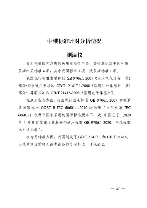
中俄标准比对分析情况测温仪针对疫情防控急需的医用测温仪产品,共收集比对中国和俄罗斯相关标准4项,其中我国标准3项,俄罗斯标准1项。
我国现行标准主要包括GB9706.1-2007《医用电气设备第1部分:安全通用要求》、GB/T21417.1-2008《医用红外体温计第1部分:耳腔式》和GB/T21416-2008《医用电子体温计》。
在通用安全方面,我国现行国家标准GB9706.1-2007和俄罗斯国家标准GOST R IEC60601-1-2010均采用了国际标准IEC 60601-1,但两个国家采用的国际标准版本不一致。
中国已于2020年4月9日发布了新版安全通用标准GB9706.1-2020。
中俄标准比对详见表1。
在专用标准方面,我国制定了GB/T21417.1和GB/T21416。
而俄罗斯目前暂无该类设备的专用标准。
详见表2。
—37—表1医用测温仪国内外标准比对-安全通用标准国家标准号标准名称与国际标准的对应关系中国GB9706.1-2007医用电气设备第1部分:安全通用标准IEC60601-1:1995,IDT 俄罗斯GOST R IEC60601-1-2010医用电气设备第1部分:基本安全和基本性能的通用标准IEC60601-1:2005,IDT差异分析1、各国家标准与国际标准对应关系:——中国标准等同采用国际标准IEC60601-1:1995。
注:2020年4月9日,中国发布新版安全通用标准GB9706.1-2020,新标准修改采用国际标准IEC60601-1:2012,与国际标准相比较,没有重要技术指标的修改。
——俄罗斯标准等同采用国际标准IEC60601-1:2005。
2、国际标准各版本间比较:IEC60601-1:2012取消并代替了IEC60601-1:2005,而IEC60601-1:2005取消并代替IEC60601-1:1995。
——相对于IEC60601-1:1995,IEC60601-1:2005主要作了如下技术内容的修改:•增加了对基本性能识别的要求•增加了机械安全的相关要求•区分了对操作者的防护和患者防护不同的要求•增加了防火的要求——IEC60601-1:2012与IEC60601-1:2005之间无关键性技术指标的变化。
医用呼吸机国内标准与国外标准对比
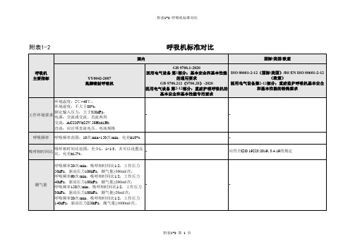
对于预期传输通气量>300mL的呼吸机,每分 钟通气量30L/min;对于300 mL≥预期传输通气 量≥50 mL的呼吸机,每分钟通气量15L/min; 对于预期传输通气量≤50mL的呼吸机,每分钟 通气量5L/min。
对于预期传输通气量>300mL的呼吸机,每分钟通气量 30L/min;对于300 mL≥预期传输通气量≥50 mL的呼吸 机,每分钟通气量15L/min;对于预期传输通气量≤ 50mL的呼吸机,每分钟通气量5L/min。
系统承受的压 呼吸机系统应能承受至少1.5倍于额定输入压力的 力(气道压力) 压力而不破损和泄露。
在额定输入压力范围内,呼吸机应能正常运行 并满足本部分的要求;在1000 kPa的单一故障 状态下不应导致不可接受的风险。最大额定输 入压力超过600kPa的呼吸机,在两倍最大额定 输入压力的单一故障状态下,不应导致不可接 受的风险。
附表1-2 呼吸机标准对比
附表1-2
呼吸机标准对比
国内
国际/美国/欧盟
呼吸机 主要指标
YY0042-2007 高频喷射呼吸机
环境温度:5℃~40℃;
环境湿度:不大于80%;
工作环境要求
额定输入压力:大于350kPa; 电源:交流或交流、直流两用
交流:AC220V±22V 50Hz±1Hz
直流:应注明直流电压、电池规格
氧浓度
输出气体的最高氧浓度应该至少能够达到85%。
呼吸机应能向患者提供含氧的气体,其浓度从 环境浓度到至少90%氧浓度。 当气源的失效使输送的氧浓度的改变超过体积 氧气浓度范围:30-90% 分数3%时,则技术报警状态宜至少为中优先 级。
耗氧量 呼吸机连续使用24h,氧气瓶规格为12.25MPa/40L -
脉搏血氧仪设备临床评价技术审查指导原则
脉搏血氧仪设备临床评价技术审查指导原则本指导原则旨在为申请人准备脉搏血氧仪设备(以下简称“血氧仪”)临床评价提供具体建议,并规范血氧仪临床评价资料的技术审评要求。
本指导原则是对血氧仪临床评价的一般性要求,制造商应依据血氧仪的特性对临床评价资料的内容进行充实和细化。
制造商还应依据血氧仪的特性确定其中的具体内容是否适用,若不适用,需具体阐述其理由及相应的科学依据。
本指导原则是在现行法规和标准体系以及当前认知水平下、并参考了国外法规与指南、国际标准与技术报告制定的。
随着法规和标准的不断完善,以及认知水平和技术能力的不断提高,相关内容也将适时进行修订。
本指导原则是对制造商和审查人员的指导性文件,不包括审评审批所涉及的行政事项,亦不作为法规强制执行,应在遵循相关法规的前提下使用本指导原则。
一、适用范围本指导原则适用于脉搏血氧仪设备,包括脉搏血氧仪主机、血氧探头和探头延长电缆(如提供),其中探头延长电缆和血氧探头可组合成单一的部件。
本指导原则所述的血氧仪包含预期测量和监护脉搏血氧饱和度的各种设备或系统。
血氧仪可以单次测量或连续测量脉搏血氧饱和度,或是独立设备或集成在多参数模块的设备或系统中。
血氧仪可以使用透射、反射或散射方式,其中,透射、反射或散射方式指的是血氧探头几何结构,而不是指血氧仪的原理、光在血红蛋白上的作用机理。
本指导原则对于血氧仪的测量部位、预期使用环境等不做限制,例如,血氧仪的测量部位包含但不限于手指、耳、足、手、前额,背和鼻,血氧仪预期在医疗机构或在家庭中使用,等等。
二、基本要求制造商应提供血氧仪的下述信息:(一)综述信息1.临床机理、工作原理/作用机理、实现方法,例如,功能血氧饱和度或氧合血红蛋白、脉搏血氧饱和度的测量原理,等等;2.设计特点和功能,3.特殊的规格参数和性能指标,例如,连续测量的血氧仪是否包括过低的脉搏血氧饱和度?4.血氧仪采用单次测量还是连续测量方式?5.血氧仪是独立设备还是集成在多参数模块设备或系统中?6.所有的患者应用部分,例如,血氧探头,患者电缆,延长电缆,传感器,绑带,等等。
HAMILTON-T1 操作手册说明书

HAMILTON-T1操作手册© 2021 哈美顿医疗公司。
版权所有。
在瑞士印刷。
未经Hamilton Medical 哈美顿医疗公司事先书面许可,不得以任何形式或通过任何手段(电子、机械、复印、录制或其他方式)复制本出版物的任何部分或将其存储到数据库或检索系统中或进行传播。
Hamilton Medical 哈美顿医疗公司可以在不另行通知的情况下随时修订或更换本手册。
确保您具有本手册最新的适用版本;如有任何疑问,请与 Hamilton Medical 哈美顿医疗公司市场营销部门联系。
尽管此处提供的信息准确无误,但并不能代替专业判断。
本手册不以任何方式限制或约束 Hamilton Medical 哈美顿医疗公司不另行通知即修订或以其他方式更改或修改此处所述设备(包括设备软件)的权利。
除非有明确书面协议,否则 Hamilton Medical 哈美顿医疗公司无义务向此处所述设备(包括软件)的所有者或用户告知任何此类修订、更改或修改。
本设备只能由经过培训的专业人员操作和维修。
对于该设备及其用途,Hamilton Medical 哈美顿医疗公司仅承担本手册提供的“有限保修”中规定的责任。
Hamilton Medical 哈美顿医疗公司的注册商标如下:INTELLiVENT®-ASV,ASV®Masimo SET® 是 Masimo 公司的注册商标。
Aeroneb®是Aerogen 公司的注册商标。
Capnostat®是Philips Respironics 公司的注册商标。
此处提及的其他产品和公司名称可能是其各自所有者的商标。
Hamilton Medical 哈美顿医疗公司将根据要求提供电路图、组件配件列表、描述、校准说明或其他信息,这些信息将帮助用户的已获得授权且已经过培训的员工维修 HamiltonMedical 哈美顿医疗公司认为可维修的那些设备配件。
THD2FE非接触前额温度计说明书
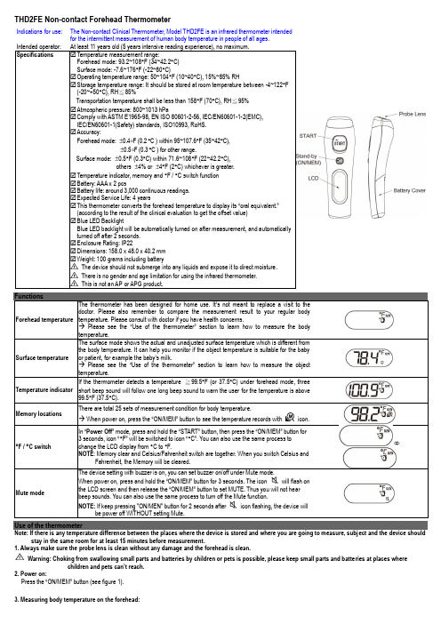
THD2FE Non-contact Forehead Thermometer⇔The device setting with buzzer is on, you can set buzzer on/off under Mute mode.beep sounds. You can also use the same process to turn off the Mute function.Use of the thermometerNote: If there is any temperature difference between the places where the device is stored and where you are going to measure, subject and the device should stay in the same room for at least 15 minutes before measurement.1. Always make sure the probe lens is clean without any damage and the forehead is clean. Warning: Choking from swallowing small parts and batteries by children or pets is possible, please keep small parts and batteries at places wherechildren and pets can’t reach.2. Power on:Press the “ON/MEM ” button (see figure 1).3. Measuring body temperature on the forehead:Indications for use: The Non-contact Clinical Thermometer, Model THD2FE is an infrared thermometer intended for the intermittent measurement of human body temperature in people of all ages.Ref No.:032020Press the “ON/MEM” button to power on the device. Forehead mode is the default mode. You can see the icon on the screenand hear two beep sounds (see figure 1). In this mode, you can hold the thermometer within 1.5 inch from the central forehead (Fig. 2) andpressthe "START" button to get the forehead measurement. The time consuming for measurement might be 1 second. After each foreheadmeasurement, wait icon stop flashing to be ready for next measurement.Figure 2 Points for attention:a. Forehead temperature is displayed in oral mode. This mode converts the forehead temperature to display its “oral-equivalent” value.b. Before the measurement, the subject should stay in a stable environment for 5 minutes and avoid exercise, bath for 30mins.c. Remember to keep the forehead area clean and away from sweat, cosmetics and scar while taking temperature.d. The “Clinical Bias” is -2.5 ~ -3.1°F (-1.4 ~ -1.7°C).e. The “Limits of Agreement” is 0.98.f. The "Repeatability" is 0.36°F (0.20°C)4. Measuring surface temperature:4.1 After power on, press and hold the “ON/MEM” button, and press the “START” button one time for “Infrared thermometer” mode to see icon on your LCDdisplay. In this mode, you can get the target surface temperature.4.2 When you press the “START” button, you will get the real time temperature immediately. If you press and hold the “START” button, the reading of measurement willbe continuously updated.4.3 Applications include temperature measurements for water, milk, cloth, skin or other objects.* Note: This mode shows the actual and unadjusted surface temperature which is different from the body temperature.5. Power off:5.1 Device will automatically shut off if left idle for more than 1 minute to extend battery life.ProblemWarranty:Warranty: 12 monthsManufacture Date: as the serial number (please open the battery cover, it is shown on the inside of the device.)Ex.SN:E512A000001, the first “E” is External, the second number “5” is the last number of manufacture year, the third and the fourth number “12” is the manufacture Note: The thermometer is calibrated at the time of manufacture. If you question calibration mode, the accuracy of temperature measurements or unexpected events at any time, please contact the dealers or nearest service address.Warning: No modification of this equipment is allowed.Please read the instructions for use BF type applied partMetris instrument east, IIcAdd: 25 Long Meadow PlaceSouth Setauket, NY USA 11720Figure 1 Figure 2 Figure 3IP220,120,23 FM c)±5 kHz deviation1 kHz sine。
QC080000的相关资料
前言世界范围内许多现行或待决的法规中,有许多要求消除产品中一系列的危害物质。
如欧盟RoHS指令将于2006年7月1日正式实施,它要求消除电子电气产品中含有的铅、汞、镉、六价铬、多溴联苯、多溴联苯醚等。
但是,要求对危害物质进行控制的法规层出不穷,客户对危害物质的要求也互有异同,各大公司一般都有自己的管理规范出台。
组织在危害物质管理方面面临巨大压力。
要想比较有效地解决这个问题,必须有世界范围内权威的标准或规范出台,让所有相关方有一个统一而明确的遵循准则,从而达到国际间产品贸易的技术壁垒最小化,有效地保护环境。
为应对上述的危害物质管理标准化的问题,IEC委托其下属的电子元器件质量评定委员会(IECQ)制订了专门的危害物质过程管理(HSPM)标准——“电子电器元件和产品危害物质过程管理体系要求(QC 080000)”,并为开展这一过程管理体系的认证制定了专门的程序规则——“危害物质过程管理要求(QC 001002-5)”,从而为危害物质管理和认证提供了较为权威的选择。
一、供应商、客户可能面临的困境●作为供应商,您有没有因面对不同客户的五花八门的危害物质要求和检查而晕头转向疲惫不堪?您知道自己的产品含有哪些物质而可能被顾客拒收吗?哪些材料中可能含有这些物质?您知道对哪些环节进行控制才能有效保证产品中不含受限物质吗?您知道如何进行管理才能持续保证产品中不含受限物质吗?您是否希望出现类似ISO9001等的国际标准用于指导对危害物质的管理?●作为客户,您有没有因为不知如何对供应商进行管理才能持续有效地确保公司采购的部品满足危害物质管理的要求而战战兢兢?是否会因仅有供应商一纸空白保证而心理发虚?有没有频繁地要求供应商进行产品检验而引发供应商怨声载道?有没有因频繁的对供应商进行“查厂”而感到力不从心?有没有即使频繁“查厂”仍无法保证采购的部品持续满足要求?我们应该如何做才能保证欧洲、日本等地的客户有没有希望出现类似ISO9001等可认证的标准来对供应商进行统一管理的渴望?解决您的困扰的最佳解决方案——国际权威的IECQ-HSPM管理体系和认证!二、迫在眉睫的各种法律法规要求和顾客要求●欧洲议会和理事会2003年1月27日第2002/95/EC号在电气电子设备中限制使用某些有害物质指令,2006年7月1日实施,禁止六种有害物质在电子电器设备中的使用。
CE认证标准清单
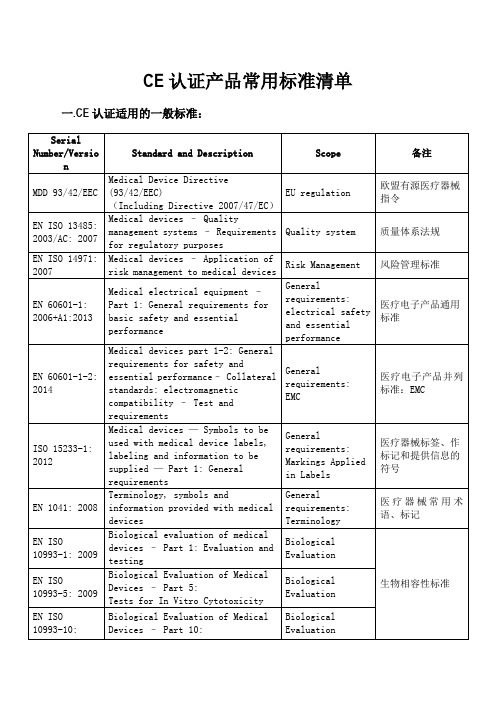
CE认证产品常用标准清单一.CE认证适用的一般标准:
二. 监护仪系列产品适用标准:
三. 生理参数检测仪适用标准:
注:生理参数检测含有的心电、血糖、无线传输功能并没有随产品做CE认证。
四. 血氧系列产品(含血氧探头)适用标准:
注:血氧探头没有IEC 60601-1-11: 2010标准。
五. 多普勒胎心仪适用标准:
六. 快速心电检测仪适用标准:
备注:第一部分属于常用标准,适用于公司做过CE认证的所有医疗产品,后面是根据产品的功能、特性附加的标准。
所以一般情况下,可用第一部分加上其他部分即可组成具体产品的适用标准。
EN 铁路应用——通信 信 和处理系统——铁路控制和防护系统软件

EN50128:2001
IV
同济大学、铁道科学研究院标准所
EN50128:2001
引言
本标准是相关标准系列中的一部分。其他标准有 EN50126 铁路应用——可靠性,可用性,可维护性和安全性 (RAMS);EN50129 铁路应用——信号领域的安全相关电子系统。EN50126 适用于大范围的系统问题,而 EN50129 适用于整个铁路控制和防护系统中某单个系统的批准过程。本标准关注于需要使用的方法,以使软件能满足经全面 考虑后所分配到的安全完整性要求。
en1060标准与iec 80601-2-30关系
EN1060是一项用于医疗电气设备的标准,而IEC xxx-2-30是一项特定的医疗电气设备标准。
两者之间存在着密切的关系,本文将探讨它们之间的关系及其重要性。
2. EN1060标准EN1060是欧洲标准化委员会(CENELEC)发布的一项标准,适用于医疗电气设备的一般要求。
该标准规定了医疗电气设备在设计、制造和使用过程中所需要满足的安全、性能和可靠性要求,以确保在医疗环境中使用时的安全性和有效性。
3. IEC xxx-2-30标准IEC xxx-2-30是国际电工委员会(IEC)发布的一项标准,专门适用于心电图设备。
它规定了心电图设备在设计、制造和使用过程中所需要满足的特定要求,以确保其在检测和记录心电信号时的准确性和可靠性。
4. 两者之间的关系EN1060标准是一项通用的医疗电气设备标准,而IEC xxx-2-30标准是一项特定的医疗电气设备标准。
在设计和制造心电图设备时,必须确保符合EN1060的通用要求,同时还需符合IEC xxx-2-30的特定要求,以保证心电图设备在医疗环境中的安全性和有效性。
符合EN1060标准和IEC xxx-2-30标准对医疗电气设备制造商和使用者来说都非常重要。
在制造过程中,遵循这两项标准可以保证设备的安全性和性能,并减少因设计或制造缺陷而引起的意外事件。
在使用过程中,遵循这两项标准可以保证医疗电气设备在医疗环境中的安全和有效使用,保护患者和医护人员的生命和健康。
6. 结论EN1060标准和IEC xxx-2-30标准是医疗电气设备领域中非常重要的标准,它们之间存在着密切的关系。
遵循这两项标准可以确保医疗电气设备在设计、制造和使用过程中的安全、性能和可靠性,并为医疗环境中的患者和医护人员提供更好的保护和看护。
制造商和使用者都应该重视并严格遵循这两项标准,以促进医疗电气设备行业的进步和发展。
7. 制造商的责任符合EN1060标准和IEC xxx-2-30标准对于医疗设备制造商来说是非常重要的。
额温枪设计方案、供应链、检测知识大全
额温枪设计方案、供应链、检测知识大全01红外额温枪新冠肺炎的突然爆发,给全球数个产业链的增长都带来了负面影响。
但疫情也让平时需求量稳定的防疫物资突然成了紧俏商品,比如口罩、酒精、消毒水。
当下,许多城市的企业已经吹起了复工的号角,额温枪也成为了新的紧俏产品。
返岗生产很重要,防控措施不能少。
除了戴口罩之外,体温筛查也成为疫情控制的一道重要防线。
通过发现体温异常人员,采取及时发现、及早隔离等措施,能够有效防止疫情的扩散。
目前人流密集的各交通关口、车站、医院、住宅小区、超市、企事业单位等等场所都在用这种红外额温枪进行体温测量。
02体温检测工具分类体温检测工具分接触式和非接触式两类:接触式:(1)玻璃体温计(水银体温计):是最常见的体温计,它可使随体温升高的水银柱保持原有位置,便于使用者随时观测;(2)电子体温计:利用某些物质的物理参数(如电阻、电压、电流等)与环境温度之间存在的确定关系,将体温以数字的形式显示出来。
非接触式:红外线体温检测仪(额温枪、耳温枪等):通过测量耳朵鼓膜或额头的辐射温度,非接触性地实现对人体温度的测量。
传统的接触式体温计,其测试时间过长、设备需与患者接触,大范围适用时存在交叉感染的风险,不适用于公共场合的快速筛查。
额温枪这一非接触式测温仪器,成为疫情防控的重点物资。
和家里日常用的水银体温计、电子体温计不同,“额温枪”根据人体发射的红外线辐射能来测定体温,所以也被称作手持红外体温检测仪。
03红外额温枪拆解分析为了更好的了解红外额温枪的技术原理,首先我们来拆解一下这种额温枪,了解其内部结构,拆开后我们会发现,其核心技术在于红外传感器和主控板部分;红外额温枪结构图▽红外额温枪拆解内部结构分析▽04红外额温枪技术原理一切温度高于零度(-273.15℃)的物体都在不停地向周围空间发射红外能量。
其辐射特性、辐射能量的大小、波长分布等都与物体表面温度密切相关。
反过来,通过对物体自身辐射的红外能量的测量,便能准确地测定它的表面温度,这就是红外辐射测温的机理。
康普产品安装要求及安装指南解读

COMMSCOPE(康普) 布线安装指南及要求本文档包含了有关安装SYSTIMAX SCS系统的重要信息,只有了解这些信息,才能保证PowerSum(5e类)和GigaSPEED XL(6类)达到或超过相关性能指标。
通用规则:_ 遵守当地的法规和相关部门的制度_ 关于通用的规划和安装惯例,请参考ANSI/TIA/EIA-568-B_ 所有的电缆和器件应能够接受目测检查,以确定正确安装_ 避免电缆进水、高湿度、化学品腐蚀和在低温下弯折电缆_ SYSTIMAX 铜缆的布放和工作温度范围在–4°F 到140°F (-20°C 到60°C)之间,在布放之前应将电缆在室温下放置至少4小时。
_ 电缆的绑扎应比较松,使绑扎带可以在电缆卷中滑动_ 不建议将电缆编成带状_ 电缆的布放不应造成电缆护套的明显变形_ 对于4对线的电缆,最大拉力不应超过110N(25磅)_ 避免电缆松弛地打圈,如果需要,要确保打圈的时候电缆没有扭绞(这会使电缆内的线对的扭绞松散)。
从面板中将模块脱出,将尾端形成松散的环。
_ 保证一定的弯曲半径,避免死弯。
4对线的铜缆的最小弯曲半径是电缆直径的四倍,柔软铜缆跳线的最小弯曲半径是跳线线径的一倍。
_ 应避免将线对去扭绞或分离开,保持线对的绞距直至电缆末端并避免缠绕。
请参考“电缆布放和处理”一章通信电缆的布放应该符合适当的走线规则,包括:_ 不能直接布放在荧光灯上_ 不能利用电力管道支撑_ 不能利用煤气或水管支撑电缆布放和处置——对电缆性能很关键图1描绘了布放SYSTIMAX 铜缆时应注意的常见问题。
图1:4线对电缆的布放和处置无护套的线对的处理和终接避免铜线破损不允许的行为避免大于90度的弯折避免外皮破裂弯曲半径为电缆直径的四倍避免紧紧地扭绞电缆可能纠结SYSTIMAX 可接受的行为(但应尽量少)22MM (0.87英寸)弯曲半径TIA 对电缆末端距离的要求以下的两页将说明处理线对的方法,这对保证电缆性能是非常关键的。
EN标准

EN标准-目录2011-06-10 14:46EN61360-1-2002电器元件标准数据元素类型和相关分类模式.第1部分_定义.原则和方法.pdfEN61360-2-2004.pdfEN61360-4-1997电子元件用带分级示意图的标准数据元类型.第4部分_标准数据元类型,元件等级和项用IEC参考文.pdfEN61360-5-2004电气元器件标准数据元素类型和相关分类模式.第5部分_EXPRESS字典图表的扩展.pdfEN61373-1999铁路设备.机车车辆设备.冲击和振动试验.pdfEN61377-1-2006.pdfEN61377-2-2002铁路设施.机车车辆.联合试验.第2部分_反向直流牵引电动机及其控制设备.pdfEN61377-3-2002铁路设施.铁路车辆.第3部分_交流电动机,间接变流器及其他控制系统的联合检验.pdfEN61378-1-1998变流器变压器.第1部分_工业用变压器.pdfEN61378-2-2001转换器变压器.第2部分_HVDC用变压器.pdfEN61386-1-2004电气装置用导管系统.第1部分_一般要求.pdfEN61386-21-2004电缆管理用导管系统.第21部分_特殊要求_刚性导管系统.pdfEN61395-1998架空电力导线.绞合导线的漏电试验.pdfEN614-1-1995机器的安全性.人类工效学设计原理.第1部分_术语和一般指导原则.pdfEN614-2-2000机器的安全性.人类工效学设计原理.第2部分_机器设计和工作目标之间的相互作用.pdfEN61400-1-2005风涡轮发电机组.第1部分_安全要求.pdfEN61400-11-2003风涡轮发电机组.第11部分_噪音测量技术.pdfEN61400-12-1998风涡轮发电机组.第12部分_风涡轮机动力特性测试.pdfEN61400-2-1996风涡轮发电机组.第2部分_小型风涡轮发电机的安全性.pdfEN61400-21-2002风轮发电机系统.第21部分_网格连接风轮的动力质量特性的测量和评定.pdf EN61427-2001.pdfEN61427-2001太阳光伏能系统用蓄电池和蓄电池组.一般要求和试验方法(IEC61427_1999)..pdfEN61429-1996带国际再循环利用符号ISO7000-1135的二次电池和蓄电池的标记.pdfEN61434-1996含碱性或其他非酸性电解质的二次充电电池和电池组.碱性二次充电电池和电池组标准电流的命名指.pdfEN61436-1998含有碱或者其它非酸性电解液的二次电池组和蓄电池组.密封式镍金属氢化物可再充电单电池组.pdfEN61442-2005电缆.额定电压从6kV(U)到30kV(U)(包括30kV....pdfEN61477-2002带电作业.工具、装置和设备利用的最低要求.pdfEN61478-2001带电作业.绝缘材料制成的梯子.pdfEN61479-2001带电作业.绝缘材料的柔性导体封盖物.pdfEN61491-1998工业机械电气设备.控制器和驱动装置间实时通信用串行数据传输线.pdfEN61496-1-2004机械安全.电敏防护设备.第1部分_一般要求和试验.pdfEN61496-3-2001机械安全.电敏防护设备.第3部分_对漫反射敏感的有源光电子保护器件的特殊要求.pdfEN61499-4-2006工业过程测量和控制系统用功能器件.第4部分_符合标杆规则.pdfEN615-1994防火.灭火剂.熄灭粉的要求(不适用于火灾等级D的熄灭粉).pdfEN61508-1-2001电气-电子-可编程电子安全相关系统的功能安全.第1部分_一般要求.pdfEN61508-2-2001电气-电子-可编程电子安全相关系统的功能安全.第2部分_电气-电子-可编程电子安全相关系统的.pdfEN61508-3-2001电气-电子-可编程电子安全相关系统的功能安全.第3部分_软件要求.pdfEN61508-4-2001电气-电子-可编程电子安全相关系统的功能安全.第4部分_定义和缩略语.pdf EN61508-5-2001电气-电子-可编程电子安全相关系统的功能安全.第5部分_确定安全整体水平方法的实例.pdfEN61508-6-2001电-电子-可编程序的电子安全相关系统的功能安全.第6部分_IEC61508-2和IEC61508....pdfEN61508-7-2001电-电子-可编程序的电子安全相关系统的功能安全.第7部分_技术和测量综述.pdfEN61511-1-2004功能安全-加工工业部门设备系统安全-第1部分:结构,定义,系统,硬件和软件要求.pdfEN61511-2-2004功能安全-加工工业部门设备系统安全-第2部分:IEC61511-1的应用指南.pdf EN61511-3-2004.pdfEN61512-1-1999分批控制.第1部分_模型和术语.pdfEN61512-2-2002分批控制.第2部分_数据结构和语言导则.pdfEN61514-2-2004工业过程控制系统第2部分气动输出智能阀门定位器性能评定方法.pdfEN61514-2002工业过程控制系统.气动输出阀门定位器性能评定方法.pdfEN61515-1996矿物绝缘电缆和热电偶.pdfEN61518-2001差分压力测量仪器和关闭装置上法兰间的配合尺寸.pdfEN61523-1-2002延迟和电力计算标准.第1部分_集成电路延迟和电力计算系统.pdfEN61523-2-2002延迟计算和功率计算标准.第2部分_互补金属氧化物半导体(CMOS)专用集成电路(ASIC)程序库用配..pdfEN61534-1-2003汇流排系统第1部分_一般要求.pdfEN61537-2001电缆管理用的电缆托架系统和电缆梯架式系统.pdfEN61543-1995家用和类似用故障电流保护装置(RCDs).电磁兼容性.pdfEN61547-1995通用照明设备.电磁兼容抗扰性要求.pdfEN61549-2003多功能灯.pdfEN61557-1-19971000V交流电和1500V直流电以下的低压配电系统中的电气安全性.防护措施的检验,测量和监测设备.pdfEN61557-10-2001最高达1000V交流和1500V直流的低压分配系统的电气安全.防护测量的试验、测量或监测设备.第1.pdfEN61557-2-19971000V交流电和1500V直流电以下的低压配电系统中的电气安全性.防护措施的检验,测量和监测设备.pdfEN61557-3-19971000V交流电和1500V直流电以下的低压配电系统中的电气安全性.防护措施的检验,测量和监测设备.pdfEN61557-4-19971000V交流电和1500V直流电以下的低压配电系统中的电气安全性.防护措施的检验,测量和监测设备.pdfEN61557-5-19971000V交流电和1500V直流电以下的低压配电系统中的电气安全性.防护措施的检验,测量和监测设备.pdfEN61557-6-19981000V交流和1500V直流的低压分配系统的电气安全.防护措施的检验,测量或者监测设备.第6部分_..pdfEN61557-7-19971000V交流电和1500V直流电以下的低压配电系统中的电气安全性.防护措施的检验,测量和监测设备.pdfEN61557-8-19971000V交流电和1500V直流电以下的低压配电系统中的电气安全性.防护措施的检验,测量和监测设备.pdfEN61557-9-1999不大于1kV交流和1.5kV直流的低压配电系统的电气安全.防护测量的试验、测量或监测设备.第9部.pdfEN61558-1-1998.pdfEN61558-1-2005.pdfEN61558-2-1-1997电力变压器,供电设备及类似设备的安全.第2-1部分_一般用途网络变压器的特殊要求.pdfEN61558-2-12-2001电力变压器、供电设备及类似设备的安全.第2-12部分_恒压变压器的特殊要求.pdfEN61558-2-13-2000电力变压器、供电设备及类似设备的安全.第2-13部分_通用自耦变压器的特殊要求.pdfEN61558-2-15-2001电力变压器,供电元件和类似件的安全要求.第2-15部分_医疗场所供电隔绝变压器的特殊要求..pdfEN61558-2-17-1997电力变压器,供电设备及类似设备的安全.第2-17部分_开关式供电用安全变压器的特殊要求.pdfEN61558-2-19-2001电力变压器,供电设备及类似设备的安全.第2-19部分_扰乱衰减变压器的特殊要求.pdfEN61558-2-2-1998电力变压器,供电设备及类似设备的安全性.第2-2部分_控制变压器的特殊要求.pdfEN61558-2-20-2000电力变压器,供电单元和类似装置的安全性.第2-20部分_小反应器的特殊要求.pdfEN61558-2-23-2000电力变压器,供电单元和类似装置的安全性.第2-23部分_施工地点的特殊要求.pdfEN61558-2-3-2000电力变压器、供电设备及类似设备的安全.第2-3部分_燃气及燃油燃烧器用点火变压器的特殊要.pdfEN61558-2-4-1997电力变压器,供电设备及类似设备的安全.第2-4部分_一般用途隔离变压器的特殊要求.pdfEN61558-2-5-1998电力变压器,供电设备及类似设备的安全.第2-5部分_电动剃须刀插座变压器和电动剃须刀插座组.pdfEN61558-2-6-1997电力变压器,供电设备及类似设备的安全.第2-6部分_一般用途安全变压器的特殊要求.pdfEN61558-2-7-1997电力变压器,供电设备及类似设备的安全.第2部分_玩具用变压器的特殊要求.pdfEN61558-2-8-1998电力变压器,供电设备及类似设备的安全.第2-8部分_铃声和钟声变压器的特殊要求.pdfEN61558-2-9-2003电力变压器、供电设备及类似设备的安全.第2-9部分_Ⅲ类手用钨丝灯的压变压器的特殊要求.pdfEN61580-4-1998波导的测量方法.第4部分_波导衰减和波导组件.pdfEN61587-1-1999电子设备的机械结构.IEC60917和IEC60297的试验.第1部分_箱、支架、辅助支架和底盘....pdfEN61588-2-12-2001.pdfEN61595-2-1998研究用数字多声道录音机(DATR),线圈系统.第2部分_格式B.pdfEN61595-3-1999专业用多声道数字磁带录音机(DATR),盘式录音系统.第3部分_16比特媒体的24比特操作.pdfEN61599-1999视盘播放器.测量方法.pdfEN61603-2-1997使用红外线辐射的声频和-或视频设备及相关信号的传输.第2部分_声宽频带和有关信号用传输系统.pdfEN61603-3-1998用红外线辐射的音频和-或视频及相关信号的传输.第3部分_会议及类似系统的音频信号传输设备.pdfEN61603-6-2002用红外线辐射的音频和-或视频及相关信号的传输.第6部分_视频及射频可视信号.pdfEN61605-2005电子和通信设备中用固定导线的标记代码.pdfEN61619-1997绝缘液.多氯联苯的污染度(PcBs).毛细管气体色谱测定法.pdfEN61621-1997干燥固体绝缘材料.耐高压低电流电弧放电的试验.pdfEN61643-11-2002低压浪涌保护装置.第11部分_接到低压配电系统的浪涌保护装置.要求和试验.pdfEN61643-21-2001低压浪涌保护装置.第21部分_接到通信和信号网络的浪涌保护装置.性能要求和试验方法(IEC6164.pdfEN61643-311-2001低压浪涌保护装置元件.第311部分_气体放电管规范.pdfEN61643-321-2002低压浪涌保护装置元件.第321部分_雪崩击穿二极管(ABD)规范.pdfEN61643-331-2003低压浪涌保护装置的元件第331部分_金属氧化物变阻器(MOV)的规格.pdfEN61643-341-2001低压浪涌保护装置.第341部分_半导体闸流管平压装置(TSS)规范.pdfEN61646-1997薄膜地面光电(PV)模数.设计质量和型号核准.pdfEN61660-1-1997短路电流.发电厂和变电所中直流自备电源设备的短路电流.第1部分_短路电流的计算.pdfEN61660-2-1997短路电流.发电厂和变电所中直流辅助设备的短路电流.第2部分_效应计算.pdf EN61663-1-1999避雷保护.通信线.第1部分_纤维光学安装.pdfEN61663-2-2001避雷保护.通信线.第2部分_使用金属导体的通信线.pdfEN61666-1997工业系统.装置,设备和工业产品.系统中终端连接的标识.pdfEN61672-1-2003电声学.声级计.第1部分_规范.pdfEN61672-2-2003电声学声级仪第2部分_模型评估测试.pdfEN61676-2002医用电气设备.在放射诊断中X射线管电压的无伤害性测量用剂量测定仪器.pdf EN61683-2000.pdfEN61685-2001超声学.流量测量系统.流量试验物体.pdfEN61689-1996超声波学.物理治疗系统.频率在0.5MHz和5MHz范围内的测量方法和性能要求.pdfEN61691-2-2001行为语言.第2部分_硬件说明语言(VHDL)多种语言的逻辑系统互运算能力.pdf EN61691-3-3-2001行为语言.第3-3部分_硬件说明语言(VHDL)的综合性.pdfEN617-2001连续搬运设备和系统.筒仓、漏斗、储存斗和装料斗中存储散装物料设备的安全性和EMC要求.pdfEN61701-2000.pdfEN61702-1999直接连接的光电(PV)泵装置的额定值.pdfEN61703-2002可靠性、有效性、维修性和维修支持术语的数学表示法.pdfEN61709-1998电子元件.可靠性.衰弱率的标准条件和换算用负载模型.pdfEN61721-1999光电组件对意外冲击损伤的灵敏度(抗冲击试验).pdfEN61721-2000.pdfEN61724-1999.pdfEN61726-2000电缆配件、电缆、连接器和无源微波元件.利用混响室法测量滤屏衰减.pdfEN61727-1995光电器件(PV)系统.网络接口的特性.pdfEN61733-1-1996测量继电器和保护设备.通讯接口防护.第1部分_总则.pdfEN61744-2001光纤色散试验装置的校准.pdfEN61746-2005光学时间域反射计(OTDR)的校准.pdfEN61747-1-A1-2003.pdfEN61747-2-1-2001液晶和固体显示器.第2-1部分_无源矩阵单色液晶显示模件.空白详细规范.pdfEN61747-3-1-1999液晶和固态显示装置.第3-1部分_液晶显示(LCD)电池.空白详细规范.pdfEN61747-3-1999液晶和固态显示装置.第3部分_液晶显示(LCD)电池分规范.pdfEN61747-4-1998液晶和半导体显示元件.第4部分_液晶显示模件和电池.基本额定值和特性.pdf EN61747-5-1998液晶和半导体显示元件.第5部分_环境检验法.寿命检验法和机械检验法.pdf EN61751-1998电信用激光模量.可靠性评定.pdfEN61753-021-2-2002纤维光学互连器件和无源元件性能标准.第021-2部分_C类单模光纤连接器终端.控制环境.pdfEN61753-051-3-2002光纤互连装置和无源部件性能标准.第051-3部分_U类非受控环用的固定式衰减器单模纤维.pdfEN61753-052-3-2002光纤互连装置和无源部件性能标准.第052-3部分_非控制环境U目录用带尾纤的固定式单膜光纤.pdfEN61753-1-1-2001光纤互连装置和无源部件性能标准.第1-1部分_总则和指南.互连装置(连接器).pdfEN61753-2-1-2000光纤互连装置和无源部件性能标准.第2-1部分_端接于U等级单模纤维的光纤连接器.非受控环境.pdfEN61753-2-3-2001光纤互连装置和无源部件性能标准.第2-3部分_U类非连接式单模1PtN和2PtN无波长选定分支器件.pdfEN61754-10-2005纤维光学连接器接口.第10部分_小型MPO连接器系列.pdfEN61754-12-1999光纤连接器接口.第12部分_FS型连接器系列.pdfEN61754-13-1999光纤连接器接口.第13部分_FC-PC型连接器系列.pdfEN61754-15-2001光纤连接器接口.第15部分_LSH型连接器系列.pdfEN61754-16-2000光纤连接器接口.第16部分_PN型连接器系列.pdfEN61754-18-2002光纤连接器接口.第18部分_MT-RJ型连接器系列.pdfEN61754-19-2002纤维光学连接器接口.第190部分_SG型连接器门类.pdfEN61754-20-2002纤维光学连接器接口.第20部分_LC型连接器门类.pdfEN61754-21-2005纤维光学连接器接口.第21部分_塑料光纤的SMI型连接器系列.pdfEN61754-22-2005分规范.光波导体和光导电缆用插塞连接件.F型.SMA.pdfEN61754-23-2005.pdfEN61754-3-2002纤维光学连接器接口.第3部分_LSA型连接器门类.pdfEN61754-4-1997光纤连接器接口.第4部分_SC型连接器系列.pdfEN61754-5-2005纤维光学连接器接口.第5部分_MT型连接器族.pdfEN61754-6-1-2003纤维光学连接器接口第6-1部分_MU型连接器门类简化插座MU-PC连接器接口.pdfEN61754-6-1997光纤插塞连接器的插塞面.第6部分_MU型插塞连接器系列.pdfEN61754-7-2005光纤连接器接口.第7部分_MPO型连接器系列.pdfEN61754-7-A1-2001.pdfEN61754-7-A2-2001.pdfEN61754-9-2001光纤连接器接口.第9部分_DS型连接器族.pdfEN61770-1999与总水管连接的电气装置.软管装置坏了虹洗的避免.pdfEN61773-1996架空线.承载结构基础试验.pdfEN61779-1-2000燃气测量和检测用电气装置.第1部分_一般要求和试验方法.pdfEN61779-2-2000燃气测量和检测用电气装置.第2部分_指示空气中甲烷含量达到百分之五的一组装置的性能要求.pdfEN61779-3-2000燃气测量和检测用电气装置.第3部分_指示空气中甲烷含量达到百分之百的一组装置的性能要求.pdfEN61779-4-2000燃气测量和检测用电气装置.第4部分_指示空气中低爆炸性气体体积所占容积达到百分之百的二组.pdfEN61779-5-2000燃气测量和检测用电气装置.第5部分_指示气体体积占百分之百的二组装置的性能要求.pdfEN61784-1-2004测量和控制用的数字数据通信第1部分:工业控制系统中涉及现场总线的连续和不连续生产的设备.pdfEN61788-11-2003超导体第11部分_剩余电阻率测量Nb_下标3_Sn复合超导体的剩余电阻率.pdf EN61788-13-2003超导体第13部分:交流损耗测量磁力计法测量铜-铌-钛多纤维复合超导体中的滞后损失.pdfEN61788-8-2003超导体第8部分:交流损耗测量铜-铌-钛复合超导体导线暴露在用电磁感应线圈方法产生的横向交.pdfEN61788-9-2005.pdfEN61800-1-1998可调速的电驱动系统.第1部分_一般要求.低电压可调速的直流电驱动系统的额定规范.pdfEN61800-2-1998可调速的电驱动系统.第2部分_一般要求.低电压可调频的交流电驱动系统的额定规范.pdfEN61800-3-2004.pdfEN61800-3-2004可调速电力传动系统.第3部分_包括特定试验方法的电磁兼容(EMC)产品标准.pdfEN61800-4-2003可调速的电气动力驱动系统.第4部分_一般要求.大于1000V但不超过35KV交流电的交流动力驱动系.pdfEN61800-5-1-2003可调速电力传动系统第5-1部分_安全要求电,热和能量.pdfEN61804-2-2004加工控制用器件功能.第2部分_器件功能的概念和电子器件的叙述语言.pdf EN61808-2000含碱或其它非酸性电介质的二次电池和蓄电池组.密封的镊金属氢化物按钮式可再充电的单电池.pdfEN61809-2000含碱性或其它非酸性电解质的二次电池和蓄电池组.便携式密封碱性二次电池和蓄电池组的安全要求.pdfEN61810-1-2004机电式非定时限有或无继电器.第1部分_一般要求.pdfEN61810-2-2005机电式非定时限有或无继电器.第2部分_可靠性.pdfEN61811-1-1999已评定质量的机电非特定的_有_或_无_继电器.第1部分_通用规范.pdfEN61811-10-2003经质量评定的机电式有或无继电器.第10部分_分规范.工业用继电器.pdfEN61811-11-2003经质量评定的机电式有或无继电器.第11部分_空白详细规范.工业用继电器.pdfEN61811-50-2002机电式_有_或_无_继电器.第50部分_经评定质量的机电式_有_或_无_电信继电器.pdfEN61811-51-2002机电式_有_或_无_继电器.第51部分_经评定质量的非标准化类型和结构的机电式_有_或_无_电信.pdfEN61811-52-2002机电式_有_或_无_继电器.第52部分_经评定质量的两组转换触点的20mmx10mmbas....pdfEN61811-53-2002机电式有或无继电器.第53部分_空白详细规范.经质量评定的机电式有或无电信继电器.14mmX9....pdfEN61811-55-2002机电式有或无继电器.第55部分_空白详细规范.经质量评定的机电式有或无电信继电器.11mmX7....pdfEN61812-1-1996工业用规定时间的时间继电器.第1部分_要求和检验.pdfEN61812-1-1999.pdfEN61821-2003机场照明和航路信标用电气装置.航空地面照明恒流串联电路的维修.pdfEN61829-1998晶硅光电(PV)矩阵.I-V特性现场测量.pdfEN61834-1-1998录制.家用6,35mm磁带上用数字倾斜磁迹录制的录像磁带系统(525-60,625-50,1125-....pdfEN61834-10-2001记录.客户使用的6,35mm磁带垂直扫描数字磁带记录系统..pdfEN61834-2-1998录制.家用6,35mm磁带上用数字倾斜磁迹录制的录像磁带系统(525-60,625-50,1125-....pdfEN61834-3-2000录制.家用6,35mm磁带上用数字倾斜磁迹录制的录像磁带系统(525-60,625-50,1125-....pdfEN61834-4-1998录制.家用6,35mm磁带上用数字倾斜磁迹录制的录像磁带系统(525-60,625-50,1125-....pdfEN61834-5-1998录制.家用6,35mm磁带上用数字倾斜磁迹录制的录像磁带系统(525-60,625-50,1125-....pdfEN61834-6-2000记录.用户使用的用6,35mm磁带的垂直扫描数字视频录像系统.第6部分_SDL 格式.pdfEN61834-7-2001录制.使用6.35mm磁带的用户用(525-60、625-50、1125-60和1250-50系统)....pdfEN61834-8-2001录音.用户用(525-60、625-50、1125-60和1250-50系统)6.35mm磁带的螺旋....pdfEN61834-9-2001录制.使用6.35mm磁带的用户用(525-60、625-50、1125-60和1250-50系统)....pdfEN61835-1998在12,65MM(0,5in)磁带上用数字组成的信号进行螺旋扫描的盒式录像带系统.D-5格式.pdfEN61837-2-2000频率控制和选择用表面安装的压电器件.标准外形和终端引线的连接.第2部分_陶瓷封装.pdfEN61837-3-2000频率控制和选择用表面安装的压电器件.标准外形和终端引线的连接.第3部分_金属封装.pdfEN61842-2002通信用的扩音器和耳机.pdfEN61846-1998超声波.压力脉冲碎石器.电磁场特性.pdfEN61850-10-2005变电所的通信网络和系统.pdfEN61850-7-1-2003配电站中的通信网络和系统-第7-1部分_配电站和补给设备原理和模型的基本通信结构.pdfEN61850-7-4-2003配电站中的通信网络和系统-第7-4部分_配电站和补给设备兼容的逻辑节点种类和数据种类的基.pdfEN61850-8-1-2004变电所的通信网络和系统.第8-1部分_专用通信设施映像(SCSM).MMS(ISO9506-1和I....pdfEN61850-9-1-2003配电站中的通信网络和系统-第9-1部分_特殊通信服务规划(SCSM)对连续单向多支路点对点连.pdfEN61851-1-2001电力道路车辆的电气设备.电动车辆感应充电系统.一般要求.pdfEN61851-21-2002电力道路车辆的电气设备.电动车辆感应充电系统.第2-1部分_传导连接到直流-交流电源上的电动.pdfEN61851-22-2002电力道路车辆的电气设备.电动车辆感应充电系统.第2-2部分_交流电动车辆充电站.pdfEN61854-1998架空线.隔离架的要求和检验.pdfEN61857-1-2005电绝缘系统.热评估过程.第1部分_一般要求.低电压.pdfEN61857-21-2004电气绝缘系统热评估过程第1部分_一般用途模型的特殊要求绕线应用.pdf EN61857-22-2002电气绝缘结构.热评定规程.第22部分_密封圈模型的特殊要求.绕线电气绝缘结构(EIS).pdfEN61858-2005电绝缘系统.对已确立绕组线EIS改进的热评估.pdfEN61883-2-2005用户音频-视频设备.数字界面.第2部分_SD-DVCR数据传输.pdfEN61883-3-2005用户音频-视频设备.数字界面.第3部分_HD-DVCR数据传输.pdfEN61883-4-2005用户音频-视频设备数字界面第4部分_MPEG2-TS数据传输.pdfEN61883-5-2005用户音频-视频设备.数字界面.第5部分_SDL-DVCR数据传输.pdfEN61883-6-2002用户音频-视频设备.数字接口.第6部分_音频和音乐数据传输协议.pdfEN61897-1998架空线.架空线型风振减振器的要求和测试.pdfEN619-2002连续搬运设备和系统.成组货件机械搬运设备的安全性和电磁兼容性的要求.pdfEN61904-2000录像.用12.65mm盒式磁带并且经过数字压缩进行螺旋扫描数字元件录像格式(格式数字-L)(IEC....pdfEN61909-2000音频记录.小光盘系统.pdfEN61921-2003电力电容器.低压电力因数校正装置组.pdfEN61926-1-2000设计自动化.第1部分_所有系统的标准测试语言.所有系统的通用缩略测试语言(C-ATLAS).pdfEN61935-1-2005根据EN50173系列对平衡通信布线进行检验的规范.第1部分_电缆敷设.pdf EN61935-2-2005通用布线系统根据ISO-IEC11801对对称通信布线进行检测的规范第二部分:转接线和工作区域用...pdfEN61937-4-2003数字音频用于IEC60958的非线性PCM编码音频位流的接口第4部分:按照MPEG音频格式的非....pdfEN61937-5-2002数字音频.用于IEC60958的非线性脉冲编码调制(PCM)编码音频位流的接口.第5部分_依据DT....pdfEN61937-6-2002数字音频.用于IEC60958的非线性脉冲编码调制(PCM)编码音频位流的接口.第6部分_依据MP....pdfEN61937-7-2005数字音频.使用IEC60958的非线性脉冲编码调制(PCM)编码音频位流的界面.第7部分_根据AT....pdfEN61943-1999集成电路.生产线验收应用指南.pdfEN61947-1-2002电子投影.主要性能标准的测量和文件化.第1部分_固定分辨投影仪.pdfEN61947-2-2002电子投影.关键性能标准的测量和文献工作.第2部分_可调分辨率的投影仪.pdf EN61951-1-2003含碱性或其他非酸性电解质的二次电池和蓄电池.便携密封可再充电单电池.第1部分_镍镉电池.pdfEN61951-2-2003含碱性或气体非酸性电解质的二次电池和蓄电池.便携式密封可再充电单电池.第2部分_镍金属氢化.pdfEN61953-1998诊断X射线成像设备.乳腺X射线摄影抗散射格栅的特性.pdfEN61959-2004.pdfEN61960-2004装有碱性或其它非酸性电解液的蓄电池和电池组用于便携式的充电锂电池和电池组.pdfEN61965-2003阴极射线管的机械安全.pdfEN61966-2-1-2000多媒体系统和设备.颜色测定和管理.第2-1部分_颜色管理.非法RGB颜色空间.pdfEN61966-2-2-2003多媒体系统与设备色彩测量和管理第2-2部分_色彩管理扩展RGB色彩空间scRGB.pdfEN61966-3-2000多媒体系统和设备.颜色测定和管理.第3部分_用阴极射线管的设备.pdfEN61966-4-2000多媒体系统和设备.颜色测定和管理.第4部分_使用液晶显示屏的设备.pdfEN61966-5-2001多媒体系统和设备.颜色测定和管理.第5部分_使用等离子体显示屏的设备.pdf EN61966-7-1-2002多媒体系统和设备.颜色测定和管理.第7-1部分_彩色打印机和反射式打印机RGB输入.pdfEN61966-8-2001多媒体系统和设备.颜色测定和管理.第8部分_多媒体颜色扫描器.pdfEN61966-9-2000多媒体系统和设备.颜色测定和管理.第9部分_数码相机.pdfEN61967-1-2002集成电路.150kHz-1GHz电磁辐射的测量.第1部分_一般条件和定义.pdfEN61967-2-2005.pdfEN61967-4-2002集成电路.150KHz至1KHz电磁释放量的测量.第4部分_传导释放量的测量.1Ω-150Ω直接耦合....pdfEN61967-5-2003集成电路150kHz~1GHz电磁辐射的测量第5部分_导电辐射的测量工作台法拉第机架法.pdfEN61967-6-2002集成电路.150kHz-1GHz电磁辐射的测量.第6部分_传导放射测量.磁探测器法.pdfEN61970-301-2004能量管理系统应用程序接口(EMS-API)第301部分:公共信息模型(CIM)基础.pdfEN61977-2002光纤滤波器.一般规范.pdfEN61978-1-2001光纤无源分散补偿器.第1部分_通用规范.pdfEN61982-2-2002电动道路车辆驱动用二次电池.第2部分_动态放电性能试验和动态耐久试验.pdfEN61982-3-2001电动道路车辆推进用二次蓄电池.第3部分_性能和寿命试验(城市车辆的交通相容性).pdfEN61984-2001连接器的安全要求和试验.pdfEN61988-1-2003等离子显示屏第1部分:术语和字母符号.pdfEN61988-2-1-2002等离子体显示板.第2-1部分_光学测量方法.pdfEN61988-2-2-2003等离子显示屏第2-2部分_光电测量方法.pdfEN61988-3-1-2005.pdfEN61993-1-1999海上导航和无线电通信设备和系统.第1部分_使用甚高频数字选择呼叫(DSC)技术的船载自动发射机.pdfEN61993-2-2002海上导航和无线电通信设备和系统.自动识别系统(AIS).第2部分_一般自动识别系统的A级船载设备.pdfEN620-2002连续搬运设备和系统.散装物料搬运用固定带式传送装置的安全和电磁兼容性(EMC)要求.pdfEN62005-1-2001光纤互连装置和无源部件的可靠性.第1部分_介绍性指南和定义.pdfEN62005-2-2001光纤互连装置和无源部件的可靠性.第2部分_基于加速老化试验的可靠性的定量评定.温度和湿度..pdfEN62005-3-2001纤维光学互连器件和无源元件可靠性.第3部分_评估无源元件失效模式和失效机理的相关试验(IEC6.pdfEN62005-4-1999光纤互连装置和无源光学组件的可靠性.第4部分_产品屏蔽.pdfEN62007-1-2000光纤系统应用的半导体光电装置.第1部分_基本速率和特性.pdfEN62007-2-2000光纤系统应用的半导体光电装置.第2部分_测量方法.pdfEN62008-2005.pdfEN62011-3-1-2003绝缘材料.电工用热固性树脂基矩形和六边形横截面的工业刚性模制层压管材和杆材.第3-1部分_.pdfEN62012-1-2002在条件恶劣环境中数字通信用对绞-星绞多芯和对称电缆.第1部分_总规范.pdf EN62013-1-2002对甲烷敏感的矿中用头灯.第1部分.通用要求.爆炸风险的推定和检验.pdfEN62013-2-2000对沼气敏感的矿工用头灯.第2部分_性能和其它安全相关方面.pdfEN62014-1-2002电子设计自动化图书馆.第1部分_输入-输出缓冲器信息规范.pdfEN62018-2003信息技术设备的功率消耗测量方法.pdfEN62019-1999电气附属设备.家用电流断路器和类似设备.辅助接触单元.pdfEN62020-1998电器安装材料.家用安装和类似用途的差动电流监视器(RCMs).pdfEN62021-1-2003绝缘液体酸度的确定第1部分:自动电势滴定.pdfEN62023-2000技术信息和文件结构..pdfEN62025-2-2005高频感应部件.非电气特性和测量方法.第2部分_非电气性能的测试方法.pdf EN62028-2004数字电视接收机测量的通用方法.pdfEN62037-1999RF连接器.连接器电缆组件和电缆.互调水平测量.pdfEN62040-1-1-2003不间断电源系统(UPS).第1-1部分_操作人员经过区使用的UPS的一般和安全要求.pdfEN62040-1-2-2003不间断电源系统(UPS).第1-2部分_限制通过区使用的不间断电源系统(UPS)的一般和安全要求.pdfEN62040-3-2001不间断供电系统(UPS).第3部分_规定性能的方法和试验要求.pdfEN62041-2003电力变压器,电源组件,电抗器和类似产品电磁兼容性要求.pdfEN62044-2-2005软磁材料制芯测量方法第1部分_在低激发能级下的电磁特性..pdfEN62052-11-2003电测量仪器.一般要求、试验和试验条件.第11部分_测量仪器..pdfEN62052-21-2004电量测量设备(交流).一般要求、试验和试验条件.第21部分_资费和负荷控制设备.pdfEN62053-11-2003电量测量设备(交流)特殊要求第11部分_测动能(0.5,1和2级)的机电仪表.pdfEN62053-21-2003电量计量设备(交流电).特殊要求.静态电度表(1和2级).pdfEN62053-22-2003电量计量设备(交流电).特殊要求.静态电度表(0.2S和0.5S级).pdfEN62053-23-2003电量计量设备(交流电).特殊要求.静态无功千瓦时计(2和3级).pdfEN62053-31-1998电能测定设备(AC).特殊要求.第31部分_感应计数器或电子计数器(只限于双线系统)用脉冲输出装.pdfEN62053-52-2005.pdf。
协调标准

ISO 80601-2-56:2009
EN ISO 80601-2-56:2012
medical electrical equipment part 2-56: particular requirements for basic safety and essential performance of clinical thermometers for body temperature measurement
EN ISO14971:2012
Medical devices-Application of risk management to medical devices
ISO15223-1:2016
Medical devices--symbols to be used with medical device labels,labelling and information to be suppliedlied--part1:general requirements
A
三级文件
5
0KF.001.10.5
电子体温计总装图
A
三级文件
6
0KF.001.10.6
医用红外体温计总装图
A
三级文件
7
KF-JS-18-01
电子体温计出厂检验规范
A
三级文件
8
KF-JS-18-02
血压计出厂检验规范
0/A
三级文件
9
KF-JS-18-03
医用红外体温计厂检验规范
0/A
智能通风模式说明书

Intelligent Ventilation since 1983Mode formMode name ModeAdult/PedNeonatalVolume-controlled, flow-controlled(S)CMVBreaths are volume controlled and mandatory, including patient triggered breaths.✓--SIMV A fixed rate is set for volume-controlled mandatory breaths. These breaths can be alternated with pressure-supported spontaneous breaths.✓--Volume-controlled, flow cycled VSBreaths are flow cycled and deliver a set tidal volume to support patient-initiated breaths.✓✓Volume-targeted, adaptive pressure- controlled APVcmv Breaths are volume targeted and mandatory.✓✓APVsimv Volume-targeted mandatory breaths can be alternated with pressure-supported spontaneous breaths.✓✓Pressure-controlledP-CMV All breaths, whether triggered by either the patient or the ventilator, are pressure controlled and mandatory.✓✓P-SIMVMandatory breaths are pressure controlled. Mandatory breaths can be alternated with pressure-supported spontaneous breaths.✓✓DuoPAPMandatory breaths are pressure controlled. Spontaneous breaths can be triggered at both pressure levels.✓✓APRVSpontaneous breaths can be continuously triggered. The pressure release between the levels contributes to ventilation.✓✓SPONTEvery breath is spontaneous, with or without pressure-supported spontaneous breaths.✓✓Intelligent ventilation ASV ®Operator sets %MinVol, PEEP, and Oxygen. Frequency, tidal volume, pressure, and I:E ratio are based on physiological input from the patient.✓--INTELLiVENT ®-ASVFully automated management of ventilation and oxygenation based on physiological input from the patient. The underlying mode is ASV.✓--Noninvasive ventilationNIV Every breath is spontaneous.✓--NIV-STEvery breath is spontaneous as long as the patient is breathing above the set rate. A backup rate can be set for mandatory breaths.✓--nCPAP-PSEvery breath is spontaneous as long as the patient is breathing above the set rate. A backup rate can be set for mandatory breaths.--OHi Flow O2High flow oxygen therapy. No supported breaths.✓✓Standard: ✓ Option: O Not applicable: --HAMILTON-S1Technical specifications for SW version 2.80Ventilation modesStandard configuration and options (in alphabetical order)Functions Adult / Ped Neonatal Adjustable O2 enrichment✓✓Adjustable Volume limitation --✓Capnography, mainstream (volumetric) and sidestream O O Communication ports: CompactFlash, USB, DVI, COM (RS-232), Special interface✓✓Communication protocols: for details see Connectivity brochure O O Distributed alarm system (DAS) compatible✓✓Dynamic Lung (real-time visualization of the lungs)✓--Event log (up to 1000 events with date and time stamp)✓✓HAMILTON-H900 humidifier control via ventilator O O Heliox ventilation O O Inspiratory and expiratory hold maneuver✓✓IntelliCuff integrated cuff pressure controller✓✓IntelliSync+ (automatic inspiratory and expiratory trigger synchronization)✓--IntelliTrig (leak compensation)✓✓✓✓Languages(English, US English, Bulgarian, Chinese, Croatian, Czech, Danish, Dutch, Finnish, French, German, Greek,Hungarian, Indonesian, Italian, Japanese, Korean, Norwegian, Polish, Portuguese, Romanian, Russian,Serbian, Slovakian, Spanish, Swedish, Turkish)Manual breath / prolonged inspiration✓✓Nebulization (Aerogen§)O O Nebulization (pneumatic)✓--P/V Tool® Pro✓✓Paramagnetic O2 sensor O O Patient group✓O Paux port✓✓Print screen✓✓Screen lock✓✓Second battery (hot-swappable)O O SpO2 monitoring✓✓Standby with timer✓✓Suctioning tool ✓✓Transpulmonary pressure monitoring✓✓TRC (tube resistance compensation)✓✓Trends/Loops ✓✓Trigger, expiratory: ETS✓✓Trigger, inspiratory: flow, pressure✓✓Vent Status (Visual representation of ventilator dependancy)✓✓Standard:✓Option: O Not applicable: --HAMILTON-S1Technical performance data (in alphabetical order)Description SpecificationAutomatic expiratory base flow Adult/Pediatric.Pressure trigger: 1 l/minFlow trigger setting ≤ 2 l/min: 4 l/minFlow trigger setting > 2 l/min: 2 * Flow triggerTrigger OFF: 1 l/minIntelliSync+: 4 l/minNeonatal.Pressure trigger: 1 l/minFlow trigger setting ≤ 1 l/min: 2 l/minFlow trigger setting > 1 l/min: 2 * Flow trigger max. 6 l/minTrigger OFF: 1 l/minInspiratory pressure0 to 120 cmH2OMaximum inspiratory flow180 l/min peak flow, max. 120 l/min continuous flowMeans of inspiratory triggering Flow, pressure, or optional IntelliSync+ trigger controlMeans of expiratory triggering ETS or optional IntelliSync+ controlMinimum expiratory time 20% of cycle time; 0.1 to 0.8 sOxygen mixer accuracy± (Volume fraction of 2.5% + 2.5% of actual reading)Preoperational checks Tightness test, Flow Sensor/O2 sensor/CO2 sensor calibrationTidal volume Adult/Ped: 20 to 2000 mlNeonatal: 2 to 200 mlStandards and approvalsClassification Class IIb, continuously operating according to EC directive 93/42/EECCertification EN 60601-1:2006/A1:2013, IEC 60601-1-2:2014, ANSI/AAMI ES60601-1:2005/(R)2012, ISO80601-2-12:2011, CAN/CSA-C22.2 NO. 60601-1:14, EN ISO 5356-1:2015, ISO 80601-2-55:2011 Declaration The HAMILTON-S1 was developed in accordance with pertinent international standards andFDA guidelines. The ventilator is manufactured within an EN ISO 13485 and EN ISO 9001,Council Directive 93/42/EEC, Annex II, Article 1 certified quality management system. Theventilator meets the Essential Requirements of Council Directive 93/42/EEC, Annex I. Electromagnetic compatibility According to IEC 60601-1-2:2014Safety Class Class I, Type B applied part (ventilator breathing system, VBS), type BF applied parts CO2 sensorincluding CO2 module connector, humidifier, Aerogen§ system, nebulizer, and SpO2 sensorincluding SpO2 adapter, continuous operation according to IEC 60601-1Degree of protection IP21HAMILTON-S1Priority AlarmHigh priorityApnea time (s), ExpMinVol high/low (l/min), Oxygen high/low (%), Pressure high/low (cmH2O), Flow sensor calibration needed, Exhalation obstructed, Disconnection, Oxygen supply failedMedium priorityfTotal high/low (b/min), PetCO2 high/low (mmHg), Pressure limitation (cmH2O), Vt high/low (ml), SpO2 high/low, SpOC high/low, %leak, High PEEP, Loss of PEEP, Pulse high/low, Check flow sensor for waterLow priorityHigh SpO2, Loss of external power, Cuff leak1 CO2 option required | 2 SpO2 option required |3 Data is available only when an esophageal catheter is connected to the Paux port on the ventilator |4 For adult/pediatric patients only |5 Only available in ASV mode |6 For complete list of alarms see the Operator's manualAlarms 6Graphic type/Tab name OptionsWaveforms Paw, Flow, Volume, Off, PCO21, FCO21, Plethysmogram 2, Pes (Paux)3, Ptranspulm 3Intelligent panels Dynamic Lung 4, Vent Status, ASV Graph 5, ASV Monitor, SMPs (Secondary monitoring parameter) Trends 1-, 3-, 12-, 24-, or 96-h trend data for a selected parameter or combination of parameters LoopsPaw/Volume, Paw/Flow, Volume/Flow, Volume/PCO21Graphical patient dataPneumatic specificationsO2Input pressure 2 to 6 bar / 29 to 87 psiConnectorDISS (CGA 1240) or NIST (optional), NF (optional)Air supplyInput pressure Connector2.8 to 6 bar / 41 to 87 psi CGA 1160-AHelioxInput pressure Connector2.8 to 6 bar / 41 to 87 psi CGA 1180-A (optional)Inspiratory outlet (To patient port)ConnectorISO ID15/OD22 conical Expiratory outlet (From patient port)Connector (on expiratory valve)ISO ID15/OD22 conical Exhaust portOD30Electrical specificationsInput power 100 to 240 VAC ±10%, 50/60 Hz Power consumption 210 VA maximum BatteryElectrical specifications:12 V DC, 15 Ah Type:Lead-acidNormal operating time:Backup time: typical 1 h, Recharge time: 15 h External hot-swappable battery (optional):Electrical specifications:Type:Normal operating time:14.4 V DC, 6.6 Ah Lithium IonBackup time typically 1 h, Recharge time: 7 h With external charger: 3 hParameter (units)Range Adult/Ped Range NeonatalAdditional O2 for enrichment (%)0 to 790 to 79Apnea backup Enabled, disabled Enabled, disabledEnd PEEP (cmH2O)0 to 3580 to 358Expiratory trigger sensitivity ETS (%) 5 to 70 5 to 70Flow for Hi Flow O2 therapy (l/min) 1 to 60 1 to 12Flow pattern Square, 50% decelerating, Sine, 100%decelerating--Gender (sex)Male, Female--I:E1:9 to 4:1--%MinVol (%)25 to 350--Nebulizer Duration (min) 5 to 40 5 to 40Nebulizer Synchronization Inspiration, Exhalation, Insp. and Exh.Inspiration, Exhalation, Insp. and Exh. Oxygen (%)21 to 10021 to 100P high (cmH2O) 0 to 500 to 50P low (cmH2O) 0 to 500 to 25P ASV limit (cmH2O)10 to 110--Pat. height (cm) Pat. height (in)130 to 250 / 30 to 15050 to 100 / 12 to 60--Pause (%)0 to 70--Pcontrol (cmH2O) 5 to 100 3 to 50Peak flow (l/min) 1 to 1804PEEP/CPAP (cmH2O)0 to 500 to 25P-ramp (ms)0 to 2000 to 200Ramp speed (cmH2O/s) 2 to 5 2 to 5Pstart (cmH2O)0 to 3580 to 358 Psupport (cmH2O)0 to 1000 to 50Ptop (cmH2O)25 to 6025 to 60Rate (b/min) 1 to 120 1 to 150Sigh Enabled, disabled Enabled, disabled %TI (%) 4 to 804--TI (s)0.1 to 9.60.1 to 3T high (s) 0.1 to 300.1 to 30T low (s)0.1 to 300.1 to 30TI max (s)0.5 to 3.00.25 to 3.0Tip (s)0 to 84--Tpause (s)0 to 300 to 30TRC compensation (%)10 to 10010 to 100TRC Tube size (I.D.) (mm) 3 to 10 2.5 to 57 Parameter settings and ranges can change depending on the modeControl settings and ranges7HAMILTON-S1Parameter (units)DescriptionPressureAutoPEEP (cmH2O) Unintended positive end-expiratory pressure Paux (cmH2O)Auxiliary pressure ΔP (cmH2O)Driving pressure Pcuff (cmH2O)Cuff pressurePtrans I (cmH2O)The arithmetic mean value of Ptranspulm over the last 100 ms of the last inspiration.Ptrans E (cmH2O)The arithmetic mean value of Ptranspulm over the last 100 ms of the last expiration.PEEP/CPAP (cmH2O)PEEP (positive end-expiratory pressure) and CPAP (continuous positive airway pressure)Pmean (cmH2O) Mean airway pressure Ppeak (cmH2O) Peak airway pressurePplateau (cmH2O)Plateau or end-inspiratory pressurePminimum (cmH20)Minimum airway pressure of the previous breath cycle FlowInsp Flow (l/min)Peak inspiratory flow, spontaneous or mandatory Exp Flow (l/min)Peak expiratory flowFlow (l/min)Flow of gas to the patient during high flow oxygen therapy VolumeExpMinVol or MinVol NIV (l/min)Expiratory minute volumeMVSpont or MVSpo NIV (l/min)Spontaneous expiratory minute volume VTE or VTE NIV (ml)Expiratory tidal volumeVTESpont (ml) Spontaneous expiratory tidal volume VTI (ml)Inspiratory tidal volumeVT/IBW VT/Wt (ml/kg)Tidal volume according to ideal body weight (IBW) for adult/ pediatric patients and according to the actual body weight for neonatal patients VLeak (%) or MVLeak (l/min)Leakage percent VLeak (ml)Leakage volumeMonitoring parametersParameter (units)Range Adult/Ped Range Neonatal Trigger, Expiratory ETS, IntelliSync+ETSTrigger, Inspiratory P-trigger, Flowtrigger, IntelliSync+, Trigger OFF P-trigger, Flowtrigger, Trigger OFF Trigger, flow (l/min)0.5 to 150.1 to 5.0Trigger, pressure (P-trigger) (cmH2O)-0.5 to -15.0(below PEEP/CPAP)-0.1 to -5.0(below PEEP/CPAP)V limit (ml)-- 4 to 400Vt (ml)20 to 2000--Vtarget (ml)20 to 2000 2 to 200Weight (kg)--0.2 to 15.08 In some markets, the maximum is 20 cmH2OControl settings and ranges 7Monitoring parameters (continued)Parameter (units)DescriptionCO2FetCO2 (%) Fractional end-tidal CO2 concentrationPetCO2 (mmHg) End-tidal CO2 pressureslopeCO2 (%CO2 / l) Slope of the alveolar plateau in the PetCO2 curve, indicating the volume/flowstatus of the lungsVtalv (ml) Alveolar tidal ventilationV’alv (l/min) Alveolar minute ventilationV’CO2 (ml/min) CO2 eliminationVDaw (ml) Airway dead spaceVDaw/VTE (%)Airway dead space fraction at the airway openingVeCO2 (ml) Exhaled CO2 volumeViCO2 (ml) Inspired CO2 volumeSpO2SpO2 (%)Oxygen saturationHLI (%)Heart-Lung interaction indexPulse (1/min) PulsePlethysmogram The waveform that visualizes the pulsating blood volume, which is delivered bythe pulse oximeterSpO2/FiO2 The SpO2/FiO2 ratio is an approximation of the PaO2/FiO2 ratio, which, incontrast to PaO2/FiO2, can be calculated noninvasively and continuously PI (%)Perfusion indexPVI (%)Pleth variability indexSpCO (%)Carboxyhaemoglobin saturationSpMet (%)Methaemoglobin saturationSpHb (g/dl) (mmol/l)Total haemoglobinSpOC (ml/dl)Oxygen contentOxygen Oxygen (%) Oxygen concentration of the delivered gasTime I:E Inspiratory:expiratory ratiofSpont (b/min)Spontaneous breathing frequencyfTotal (b/min)Total breathing frequencyTI (s) Inspiratory timeTE (s) Expiratory timeLung mechanics Cstat (ml/cmH2O) Static complianceP0.1 (cmH2O) Airway occlusion pressurePTP (cmH2O*s) Pressure time productRCexp (s) Expiratory time constantRCinsp (s)Inspiratory time constantRexp (cmH2O/l/s)Expiratory flow resistanceRinsp (cmH2O/l/s)Inspiratory flow resistanceRSB (1/(l*min))Rapid shallow breathing indexVariIndex (%)Variability indexWOBimp (J/l)Imposed work of breathingHAMILTON-S1Specifications are subject to change without notice. Some features are options. Not all features are available in all markets.INTELLiVENT -ASV is not available in the US. For all proprietary trademarks (®) and third-party trademarks (§) used by Hamilton Medical AG see /trademarks. © 2018 Hamilton Medical AG. All rights reserved.689322.06Physical characteristicsManufacturer:Hamilton Medical AGVia Crusch 8, 7402 Bonaduz, Switzerland+41 (0)58 610 10 20*************************WeightVentilation unit, monitor and shelf mount: 38 kg (83.8 lb)57 kg (125.6 lb) with standard trolley, monitor, ventilation unitThe standard trolley can accommodate a maximum safe working load of 80 kg (176 lb).The universal trolley can accommodate a maximum safe working load of 140 kg (308 lb).Dimensions See graphic aboveMonitor15“ XGA, TFT color, LCD touchscreen, 3m (10 ft) cable with optional 7 m (23 ft) extension, 6.4 kg (14.1 lb)Monitor mountingPole mount, rail mount, handle mountm a x . 150.0 c m (59.0 i n )m i n . 130.0 c m (51.2 i n ) m o n i t o r m o u n t e d o n r a i l60.0 c m (23.6 i n)45.0c m(17.7i n 544 c m (17.3 i n )58.0 cm (22.8 in)。
温度计说明书
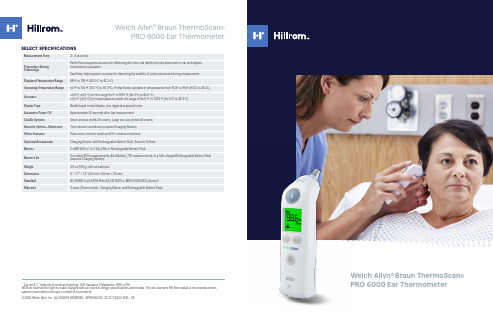
Welch Allyn ® Braun ThermoScan ®PRO 6000 Ear Thermometer1Guyton A C, Textbook of medical physiology, W.B. Saunders, Philadelphia, 1996, p 919Hill-Rom reserves the right to make changes without notice in design, specifications and models. The only warranty Hill-Rom makes is the express written warranty extended on the sale or rental of its products.© 2020 Welch Allyn, Inc. ALL RIGHTS RESERVED. APR74002 R2 23-OCT-2020 ENG - USSELECT SPECIFICATIONSWelch Allyn ® Braun ThermoScan ®PRO 6000 Ear ThermometerSmall CradleAdvanced technology and features to enhance your clinical experienceInnovative PerfecTemp ® technology adjusts for variability in probe placement.ExacTemp ® technology detects stability of the probe during measurement.A pre-warmed sensor helps support accurate measurements.Memory recall button displays last measurement taken.The C/F button provides for quick scale conversion of readings.60-second pulse timer can assist you with manual measurement of pulse rate and respirations .Our design uses plastics compatible with common medical-grade cleaning products.Electronic and mechanical security features help prevent theft and lossWHY MEASURE IN THE EAR?Clinical studies have shown that the ear is an excellent site for measurement as temperatures taken in the ear reflect the body’s core temperature.Advantages of taking temperature in the ear:.Less invasive for the patient than oral, axillary or rectal temperature measurements.No mucus membrane contact which can impact accuracy of readingsSo how does it work?When the PRO 6000 probe tip is placed in the ear, it continuously monitors the infrared energy emitted by the tympanic membrane and surrounding tissues, until a temperature equilibrium has been reached and an accurate measurement can be taken.Device options and accessoriesSmall CradleOur device cradle offers you storage for 20 probe covers and pops up for easy probe cover attachmentOptional Charging StationStores 200 probe covers, includes Rechargeable Battery Pack and enables electronic security settingsOptional Security TetherHelps you minimize theft and loss, keeping the PRO 6000 attached to its cradlePERFECTEMP ® TECHNOLOGY—THE PRO 6000 ADVANTAGEPerfecTemp technology overcomes the potential for low readings, compared to core, by adjusting for factors that impact measurement accuracyPerfecTemp technology address two main concerns with taking temperature in the ear.challenges presented by ear canal anatomy .variability in technique with probe placementWhen probe positioning is not ideal, PerfecTemp helps support the accuracy of measurement as compared to coretemperature. PerfecTemp is activated when the probe tip is placed in the ear, collecting information about the direction and depth of probe placement then accounting for this in the temperature calculation.。
ISO80601-2-70:2015测试项目-2

201.9 Protection against mechanical HAZARDS of ME EQUIPMENT and ME SYSTEMSIEC 60601-1:2005+A1:2012, Clause 9 applies, except as follows:Additional subclauses:201.9.6.2.1.101 * Additional requirements for audible acoustic energyThe A-weighted sound pressure level emitted by the SLEEP APNOEA BREATHING THERAPY EQUIPMENT shall be measured in accordance with ISO 4871:1996 and ISO 3744:2010 using engineering method grade 2 and disclosed in the instructions for use. The A-weighted sound power level shall be calculated according to 8.1 of ISO 3744:2010 and disclosed in the instructions for use.Check compliance with the following test:a) Place the SLEEP APNOEA BREATHING THERAPY EQUIPMENT on a sound-reflecting plane and attach the least favorable BREATHING GAS PATHWAY from those indicated in the instructions for use.NOTE the least favorable BREATHING GAS PATHWAY configuration can vary by mode, as applicable.b) If a HUMIDIFIER is provided with or specified in the ACCOMPANYING DOCUMENTS of the SLEEP APNOEABREATHING THERAPY EQUIPMENT, include the HUMIDIFIER in the test. Fill the HUMIDIFIER to the least favorable level.c) Connect the standard resistance, 40 mm length and outlet angle of 45° (as indicated in Figure 201.101) to the PATIENT-CONNECTION PORT.d) Acoustically isolate the BREATHING TUBES and the gas leaving at the resistance placed at the PATIENTCONNECTION PORT by a suitable means out of the testing area so that the noise caused by the BREATHING TUBE and the gas flow do not interfere with the sound measurement of the SLEEP APNOEA BREATHING THERAPY EQUIPMENT.e) Set the SLEEP APNOEA BREATHING THERAPY EQUIPMENT to the least favourable mode and flow pattern, as applicable, that generates a continuous pressure of 10 hPa (10 cmH2O) at the PATIENT-CONNECTION PORT.NOTE The least favorable mode, breath type and flow pattern can vary by BREATHING GAS PATHWAY configuration.f) Using a microphone of the sound level meter complying with the requirements of type 1 instruments specified in IEC 61672-1:2013, measure the sound pressure levels at 10 positions in a hemisphere with a radius from the geometric centre of the SLEEP APNOEA BREATHING THERAPY EQUIPMENT as specified in 7.2 of ISO 3744:2010.g) Calculate the A-weighted sound pressure level averaged over the measurement surface according to 8.1 of ISO 3744:2010.h) Calculate the A-weighted sound power level according to 8.6 of ISO 3744:2010.i) Verify that the A-weighted background level of extraneous noise is at least 6 dB below that measured during the test.j) Take measurements using the frequency-weighting characteristic A and the time-weighting characteristic F on the sound level meter in a free field over a reflecting plane as specified in ISO 3744:2010. Average the values in accordance with subclause 8.1 of ISO 3744:2010.k) Repeat b) to j) for each HUMIDIFIER provided with or specified in the ACCOMPANYING DOCUMENTS.l) Ensure that the measured sound pressure level is less than that disclosed in the instructions for use.201.11.1.2.2 A PPLIED PARTS not intended to supply heat to a PATIENTAmendment (add between the existing paragraphs):Over the RATED flow rate range and at the maximum RATED operating temperature, the temperature of the delivered gas of SLEEP APNOEA BREATHING THERAPY EQUIPMENT, both with and without a humidifier, shall not exceed an energy equivalent to 43 °C and 100 % relative humidity (a specific enthalpy not to exceed197 kJ/m3 dry gas) when averaged over 120 s.Table 201.101 contains examples of combinations of temperature and relative humidity with such a specific enthalpy.Table 201.101 — Examples of permissible combinations of temperature and relative humidity201.12.1.101 Stability of static AIRWAY PRESSURE ACCURACY (long-term accuracy) The stability of the static AIRWAY PRESSURE ACCURACY for any type of SLEEP APNOEA BREATHING THERAPY EQUIPMENT when operating in NORMAL CONDITION shall be disclosed in the instructions for use, as the maximum bias error and maximum linearity error.EXAMPLE ± (3,0 hPa + 5 % of the set pressure)NOTE 1 This information should be expressed in graphical or tabular form.The accuracy of the performance of the SLEEP APNOEA BREATHING THERAPY EQUIPMENT shall either be: determined for each BREATHING GAS PATHWAY configuration indicated in the instructions for use; or determined for the worst case BREATHING GAS PATHWAY configuration indicated in the instructions for use.If worst case BREATHING GAS PATHWAY configurations are used, the rationale for their selection shall be documented in the RISK MANAGEMENT FILE.Check compliance by inspection of the RISK MANAGEMENT FILE for the rationale, if applicable, and by inspection of the instructions for use with the following tests:a)Set up the SLEEP APNOEA BREATHING THERAPY EQUIPMENT for NORMAL USE according to Figure 201.102 with the pressure set to 10 hPa (10 cm H2O) in CPAP mode. For BI-LEVEL PAP SLEEP APNOEA BREATHING THERAPY EQUIPMENT without a CPAP mode, adjust the inspiratory and expiratory pressures to the same value. Switch off all comfort features of the ME EQUIPMENT. Place the standard resistance (Figure 201.101) at the PATIENT-CONNECTION PORT.NOTE 2 Comfort features do include, but are not limited to, e.g. automatic start / stop function,fall-to-sleep ramps, automatic inspiratory pressure increase or automatic expiratory pressure decrease.b) Using a pressure-measuring device, measure the pressure at least once per second at the PATIENTCONNECTION PORT of the BREATHING GAS PATHWAY and record, each minute, the average pressure over each averaging interval of 1 min for a period of 8 h.c) Calculate the most positive and most negative pressure difference (if applicable) referenced to the set pressure on the SLEEP APNOEA BREATHING THERAPY EQUIPMENT.d) Verify that the average measured static pressure is within the static AIRWAY PRESSURE ACCURACY limit disclosed in the instructions for use.Key1 –SLEEP APNOEA BREATHING THERAPY EQUIPMENT2 –BREATHING GAS PATHWAY3 – standard resistance (see Figure 201.101)4 – pressure meter5 –PATIENT-CONNECTION PORTFigure 201.102 – Test set-up for static AIRWAY PRESSURE ACCURACY in NORMAL USE201.12.1.102 Stability of dynamic AIRWAY PRESSURE ACCURACY(short-term accuracy)201.12.1.102.1 C PAP modeWith the SLEEP APNOEA BREATHING THERAPY EQUIPMENT operating in CPAP mode in NORMAL CONDITION, the stability of the dynamic AIRWAY PRESSURE ACCURACY shall be disclosed in the instructions for use, as the maximum bias error and maximum linearity error.EXAMPLE ± (3,0 hPa + 5 % of the set pressure)NOTE 1 This information should be expressed in graphical or tabular form.The accuracy of the performance of the SLEEP APNOEA BREATHING THERAPY EQUIPMENT shall either be:-determined for each BREATHING GAS PATHWAY configuration indicated in the instructions for use; or-determined for the worst case BREATHING GAS PATHWAY configuration indicated in the instructions for use.If worst case BREATHING GAS PATHWAY configurations are used, the rationale for their selection shall be documented in the RISK MANAGEMENT FILE.Check compliance by inspection of the RISK MANAGEMENT FILE for the rationale, if applicable, and by inspection of the instructions for use with the following tests:a) Connect the PATIENT-CONNECTION PORT to a pressure-measuring device and a pump that produces a sinusoidal cycle with an inspiratory: expiratory phase time (I/E ratio) of 1/1 and a breathing frequency of 10 breaths/min according to Figure 201.103. Switch off all comfort features of the ME EQUIPMENT. Monitor and measure the flow rate and pressure using a pressure- and flow rate-measuring device at the PATIENTCONNECTION PORT.NOTE 2 The dead space of the test lung should be less than the tidal volume used.NOTE 3 All measurement uncertainties of the test apparatus used for these tests (specified in a) and b) are to be included in the calculation of the results, i.e. uncertainties are to be added to the differences measured.b) Set the pressure to the minimum pressure setting.c) Set lung parameters according to Table 201.102 with a tidal volume, V t, of approximately 500 ml.d) Simulate an apnoea event by turning the pump off for at least 1 min.e) For each cycle, calculate the most positive and negative pressure difference from the set value. Average these results over a period of 5 min.f) Record the pressure and flow rate waveforms. If necessary, adjust the settings until the breathing frequency and stroke volume match the desired settings.g) Record the dynamic high and low pressure measurements as peak-to-peak values. Subtract the recorded dynamic low pressure from the recorded dynamic high pressure.h) Verify that the average measured dynamic pressure is within the static AIRWAY PRESSURE ACCURACY limit disclosed in the instructions for use.i) Repeat steps d) to h) for each set pressure indicated in Table 201.102.j) Repeat b) to i) for each breath rate indicated in Table 201.102.Key1 – S LEEP APNOEA BREATHING THERAPY EQUIPMENT2 – B REATHING GAS PATHWAY3 – Standard resistance (see Figure 201.101)4 – Flow meter5 – Pressure-measuring device6 – Pump that produces a sinusoidal cycle7 – P ATIENT-CONNECTION PORTFigure 201.103 – Test set-up for dynamic AIRWAY PRESSURE ACCURACY in NORMAL USEAIRWAY PRESSURE ACCURACY201.12.1.102.2 B I-LEVEL POSITIVE AIRWAY PRESSURE modeWith the SLEEP APNOEA BREATHING THERAPY EQUIPMENT operating in NORMAL CONDITION, the stability of the dynamic AIRWAY PRESSURE ACCURACY for both the inspiratory and expiratory pressure levels shall be disclosed in the instructions for use, as the mean and standard deviation of the error between the set values and the delivered values. The technical description shall disclose which percentage of each inspiratory and expiratory phase is taken into the calculation for determining the accuracy as well as where these time slots are located within the inspiratory and the expiratory phases.NOTE 1 This information should be expressed in graphical or tabular form.The accuracy of the performance of the SLEEP APNOEA BREATHING THERAPY EQUIPMENT shall either be:-determined for each BREATHING GAS PATHWAY configuration indicated in the instructions for use; or-determined for the worst case BREATHING GAS PATHWAY configuration indicated in the instructions for use.If worst case BREATHING GAS PATHWAY configurations are used, the rationale for their selection shall be documented in the RISK MANAGEMENT FILE.Check compliance by inspection of the RISK MANAGEMENT FILE for the rationale, if applicable, and by inspection of the instructions for use with the following tests:a) Connect the PATIENT-CONNECTION PORT to a pressure-measuring device and a pump that produces a sinusoidal cycle with an inspiratory:expiratory phase time (I/E ratio) of 1/1 and a breathing frequency of 10 breaths/min according to Figure 201.103. Switch off all comfort features of the ME EQUIPMENT. Monitor and measure the flowrate and pressure using a pressure- and flowrate-measuring device at the PATIENTCONNECTIONPORT.NOTE 2 The deadspace of the test lung should be less than the tidal volume used.NOTE 3 All measurement uncertainties of the test apparatus used for these tests (specified in a) and b) )are to be included in the calculation of the results, i.e. uncertainties are to be added to the differences measured.b) Set the pressure to the minimum pressure setting.c) Set lung parameters according to Table 201.103 with a tidal volume, V t, of approximately 500 ml.NOTE 4 To accommodate the different control mechanisms of different designs during the change from the inspiratory phase to the expiratory phase and vice versa measure the inspiratory pressure and expiratory pressures as specified in the technical description.d) Record the pressure and flowrate waveforms. If necessary, adjust the settings until the breathing frequency and stroke volume match the desired settings.e) Simulate an apnoea event by turning the pump off for at least 1 min.f) For each cycle, determine the extreme inspiratory pressure difference from the inspiratory set value. Calculate the mean and standard deviation of these pressures over a period of 5 min.g) For each cycle, determine the extreme expiratory pressure difference from the expiratory set value. Calculate the mean and standard deviation of these pressures over a period of 5 min.h) Verify that the mean and standard deviation of the dynamic inspiratory and expiratory pressure errors are within the limits disclosed in the instructions for use.i) Repeat steps e) to h) for each set pressure indicated in Table 201.103.j) Repeat b) to i) for each breath rate indicated in Table 201.103.Table 201.103 — Parameters for dynamic AIRWAY PRESSURE ACCURACY testing for POSITIVE201.12.1.103 Maximum flow rateThe flow rate capability of SLEEP APNOEA BREATHING THERAPY EQUIPMENT over the set pressure range shall be disclosed in the instructions for use. The disclosure may be in tabular form. Check compliance by inspection of the instructions for use and with the following tests:a) Set up SLEEP APNOEA BREATHING THERAPY EQUIPMENT with a 1,9 ± 0,15 m BREATHING TUBE.Switch off all comfort features of the ME EQUIPMENT.b) Apply a pressure-measuring device and flow rate meter to the PATIENT-CONNECTION PORT.c) Apply an adjustable valve at the PATIENT-CONNECTION PORT.d) Set the pressure to the minimum setting and adjust the valve to achieve (40 ± 2) l/min and measure the actual pressure delivered to the PATIENT-CONNECTION PORT.e) Adjust the valve until the actual measured pressure is reduced by 1 hPa ± 0,1 hPa(1 cm H2O ± 0,1 cm H2O). Read the corresponding measured pressure and flow rate value.f) Repeat step e) 10 times and record the average value of these 10 measurements.g) Verify that the SLEEP APNOEA BREATHING THERAPY EQUIPMENT can deliver at least as much flow as is indicated in the instructions for use.h) Repeat step d) to g) with each pressure as indicated in Table 201.104.Table 201.104 – S LEEP APNOEA BREATHING THERAPY EQUIPMENT flowrate performance at set201.12.4.102 * M AXIMUM LIMITED PRESSURE PROTECTION DEVICEA PROTECTION DEVICE to prevent the AIRWAY PRESSURE from exceeding the MAXIMUM LIMITED PRESSURE of 30 hPa (30 cm H2O) in NORMAL CONDITION and of 40 hPa (40 cm H2O) in SINGLE FAULT CONDITION shall be provided.Check compliance by functional testing in NORMAL CONDITION and SINGLE FAULT CONDITION. 201.101.2 Other named ports201.101.2.1 P ATIENT-CONNECTION PORTThe PATIENT-CONNECTION PORT shall be one of the following:a) a female 15 mm conical connector complying with ISO 5356-1:2004;b) a female 22 mm conical connector complying with ISO 5356-1:2004.Check compliance by application of the tests of ISO 5356-1:2004.201.101.2.2 G AS OUTPUT PORTIf provided, the GAS OUTPUT PORT shall be one of the following or not engage with any of the connectors of ISO 5356-1:2004.a) a male 22 mm conical connector complying with ISO 5356-1:2004.b) a male 15 mm conical connector complying with ISO 5356-1:2004.Check compliance by application of the tests of ISO 5356-1:2004.201.102.3 HumidificationAny HUMIDIFIER, including heated BREATHING TUBES, either incorporated into the SLEEP APNOEA BREATHING THERAPY EQUIPMENT or recommended for use with the SLEEP APNOEA BREATHING THERAPY EQUIPMENT or its BREATHING GAS PATHWAY, shall comply with ISO 8185:2007 (to be ISO 80601-2-74).201.102.4 B REATHING SYSTEM FILTER (BSF)Any BSF, either incorporated into the SLEEP APNOEA BREATHING THERAPY EQUIPMENT or recommended for use with the SLEEP APNOEA BREATHING THERAPY EQUIPMENT or its BREATHING GAS PATHWAY, shall comply with the relevant requirements of ISO 23328-1:2003 and ISO 23328-2:2002.Check compliance by application of the tests of ISO 23328-1:2003 and ISO 23328-2:2002.。
医用电气设备 第2-21部分:婴儿辐射保暖台的基本安全和基本性能专用要求

ICS11.040.55C 39 YY 中华人民共和国医药行业标准YY 0455—20XX代替YY0455-2011医用电气设备第2-21部分:婴儿辐射保暖台的基本安全和基本性能专用要求Medical electrical equipment- Part 2-21: Particular requirements for the basic safety and essential performance of infant radiant warmers(IEC 60601-2-21:2009/A1:2016,MOD)(征求意见稿)2018.6.25XXXX-XX-XX发布XXXX-XX-XX实施目次前言 (II)引言 (III)201.1范围,目的和相关标准 (1)201.2规范性引用文件 (2)201.3术语和定义 (2)201.4通用要求 (4)201.5ME设备试验的通用要求 (5)201.6ME设备和ME系统的分类 (5)201.7ME设备识别、标记和文件 (5)201.8ME设备对电击危险(源)的防护 (7)201.9ME设备和ME系统对机械危险的防护 (7)201.10对不需要的或过量的辐射危险(源)的防护 (8)201.11对超温和其他危险(源)的防护 (8)201.12控制器和仪表的准确性和危险输出的防护 (9)201.13ME设备危险情况和故障状态 (12)201.14可编程医用电气系统(PEMS) (12)201.15ME设备的结构 (12)201.16ME系统 (13)201.17ME设备和ME系统的电磁兼容性 (13)202电磁兼容性-要求和测试 (13)附录AA (资料性附录)专用指南和原理说明 (15)参考文献 (21)索引 (23)图201.101–试验装置布局 (3)图201.102–试验装置 (4)图AA.1-本标准主要要求的图解 (16)表201.101–增加的基本性能要求 (5)前言医用电气设备安全要求系列标准主要由两大部分组成:---第1部分:基本安全和基本性能的通用要求;---第2部分:基本安全和基本性能的专用要求。
- 1、下载文档前请自行甄别文档内容的完整性,平台不提供额外的编辑、内容补充、找答案等附加服务。
- 2、"仅部分预览"的文档,不可在线预览部分如存在完整性等问题,可反馈申请退款(可完整预览的文档不适用该条件!)。
- 3、如文档侵犯您的权益,请联系客服反馈,我们会尽快为您处理(人工客服工作时间:9:00-18:30)。
Reference numberISO 80601-2-56:2009(E)INTERNATIONAL STANDARD ISO80601-2-56First edition2009-10-01Medical electrical equipment —Part 2-56:Particular requirements for basic safetyand essential performance of clinicalthermometers for body temperaturemeasurementAppareils électromédicaux —Partie 2-56: Exigences particulières relatives à la sécurité fondamentaleet aux perfomances essentielles des thermomètres médicaux pour mesurer la température de corpsISO 80601-2-56:2009(E) PDF disclaimerThis PDF file may contain embedded typefaces. In accordance with Adobe's licensing policy, this file may be printed or viewed butshall not be edited unless the typefaces which are embedded are licensed to and installed on the computer performing the editing. In downloading this file, parties accept therein the responsibility of not infringing Adobe's licensing policy. The ISO Central Secretariat accepts no liability in this area.Adobe is a trademark of Adobe Systems Incorporated.Details of the software products used to create this PDF file can be found in the General Info relative to the file; the PDF-creation parameters were optimized for printing. Every care has been taken to ensure that the file is suitable for use by ISO member bodies. In the unlikely event that a problem relating to it is found, please inform the Central Secretariat at the address given below.COPYRIGHT PROTECTED DOCUMENT© ISO 2009All rights reserved. Unless otherwise specified, no part of this publication may be reproduced or utilized in any form or by any means, electronic or mechanical, including photocopying and microfilm, without permission in writing from either ISO at the address below or ISO's member body in the country of the requester.ISO copyright officeCase postale 56 • CH-1211 Geneva 20Tel. + 41 22 749 01 11Fax + 41 22 749 09 47E-mail copyright@Web Published in SwitzerlandISO 80601-2-56:2009(E)Contents PageForeword (v)Introduction (vi)201.1 * Scope, object and related standards (1)201.1. 1 Scope (1)201.1. 2 Object (2)201.1. 3 Collateral standards (2)201.1. 4 Particular standards (2)references (3)201.2 Normativeand definitions (3)201.3 Terminologyrequirements (6)201.4 General201.4. 2 R ISK MANAGEMENT PROCESS for ME EQUIPMENT or ME SYSTEMS (6)201.4. 2.101 Additional requirements for RISK MANAGEMENT PROCESS for ME EQUIPMENT orME SYSTEMS (7)201.4. 3 E SSENTIAL PERFORMANCE (7)201.4. 3.101 * Additional requirements for ESSENTIAL PERFORMANCE (7)201.4. 101 Environmental conditions of use (7)201.5 General requirements for testing of ME EQUIPMENT (7)of201.6 ClassificationME EQUIPMENT and ME SYSTEMS (7)201.7 M E EQUIPMENT identification, marking and documents (7)201.7. 2.1 Minimum requirements for marking on ME EQUIPMENT and interchangeable parts (8)201.7. 2.1.101 Additional requirements for minimum requirements for marking on ME EQUIPMENT and interchangeable parts, marking of the packaging (8)201.7. 2.2 Marking on the outside of ME EQUIPMENT or ME EQUIPMENT parts (8)201.7. 2.101 Additional requirements for marking on the outside of ME EQUIPMENT orME EQUIPMENT parts (8)201.7. 4.3 Unit of measure (8)201.7. 4.3.101 Additional requirements for unit of measure (8)201.7. 9 A CCOMPANYING DOCUMENT (9)201.7. 9.1 Additional general requirements (9)201.7. 9.2 Additional requirements for instructions for use (9)201.7. 9.2.14.101 Additional requirements for ACCESSORIES, supplementary equipment,used material (9)201.7. 9.2.101 Instructions for use (9)201.7. 9.101 Additional requirements for ACCOMPANYING DOCUMENT (10)201.8 Protection against electrical HAZARDS from ME EQUIPMENT (10)mechanicalagainst201.9 ProtectionHAZARDS of ME EQUIPMENT and ME SYSTEMS (10)201.10 Protection against unwanted and excessive radiation HAZARD s (10)201.11 Protection against excessive temperatures and other HAZARDS (10)and instruments and protection against hazardous outputs (10)controlsof201.12 Accuracy201.12. 1 Accuracy of controls and instruments (10)201.12. 1.101 Additional requirements for accuracy of controls and instruments (10)201.12. 2 U SABILITY (11)201.12. 2.101 * Additional requirements for USABILITY (11)201.13 H AZARDOUS SITUATIONS and fault conditions (11)201.14 P ROGRAMMABLE ELECTRICAL MEDICAL SYSTEMS (PEMS) (11)ISO 80601-2-56:2009(E)201.15 Construction of ME EQUIPMENT ................................................................................................11 201.16 M E SYSTEMS ...............................................................................................................................11 201.17 * Electromagnetic compatibility of ME EQUIPMENT and ME SYSTEMS . (11)201.101 Laboratory performance requirements (11)201.101. 1 * General test requirements (11)201.101. 2 * Laboratory accuracy (12)201.101. 3 * Time response for a continuous clinical thermometer ........................................................13 201.102* Clinical accuracy validation.................................................................................................13 201.102. 1Method......................................................................................................................................13 201.102. 2* Human subject population requirements...........................................................................14 201.102. 3* Clinical bias calculation.......................................................................................................15 201.102. 4* Limits of agreement calculation..........................................................................................15 201.102. 5* Clinical repeatability calculation.........................................................................................16 201.103* Probes, probe cable extenders and probe covers............................................................16 201.103. 1General.....................................................................................................................................16 201.103. 2Labeling....................................................................................................................................17 202 Medical electrical equipment — Part 1-2: General requirements for basic safetyand essential performance — Collateral standard: Electromagneticcompatibility — Requirements and tests (17)202.6.2.1.10 Compliance criteria.................................................................................................................17 AnnexesAnnex C (informative) Guide to marking and labelling requirements for ME EQUIPMENT andME SYSTEMS (19)Annex D (informative) Symbols on Marking (22)Annex AA (informative) Particular Guidance and rationale..........................................................................24 Annex BB (informative) R EFERENCE TEMPERATURE SOURCE .. (37)Annex CC (informative) Environmental aspects............................................................................................39 Annex DD (informative) Reference to the essential principles of safety and performance ofmedical devices in accordance with ISO/TR 16142 (40)Bibliography (42)Alphabetized index of defined terms used in this particular standard (45)ISO 80601-2-56:2009(E)ForewordISO (the International Organization for Standardization) is a worldwide federation of national standards bodies (ISO member bodies). The work of preparing International Standards is normally carried out through ISO technical committees. Each member body interested in a subject for which a technical committee has been established has the right to be represented on that committee. International organizations, governmental and non-governmental, in liaison with ISO, also take part in the work. ISO collaborates closely with the International Electrotechnical Commission (IEC) on all matters of electrotechnical standardization. International Standards are drafted in accordance with the rules given in the ISO/IEC Directives, Part 2.The main task of technical committees is to prepare International Standards. Draft International Standards adopted by the technical committees are circulated to the member bodies for voting. Publication as an International Standard requires approval by at least 75 % of the member bodies casting a vote.Attention is drawn to the possibility that some of the elements of this document may be the subject of patent rights. ISO shall not be held responsible for identifying any or all such patent rights.ISO 80601-2-56 was prepared by Technical Committee ISO/TC 121, Anaesthetic and respiratory equipment, Subcommittee SC 3, Lung ventilators and related equipment, in cooperation with Subcommittee 62D, Electrical equipment, of Technical Committee IEC/TC 62: Electrical equipment in medical practice.ISO 80601 consists of the following parts, under the general title Medical electrical equipment:⎯Part 2-12: Particular requirements for basic safety and essential performance of critical care ventilators⎯Part 2-13: Particular requirements for basic safety and essential performance of an anaesthetic workstation⎯Part 2-55: Particular requirements for the basic safety and essential performance of respiratory gas monitors⎯Part 2-56: Particular requirements for basic safety and essential performance of clinical thermometers for body temperature measurement⎯Part 2-61: Particular requirements for the basic safety and essential performance of pulse oximeter equipment for medical useIEC 80601-2-30: Particular requirements for basic safety and essential performance of automated non-invasive sphygmomanometers, IEC 80601-2-35: Particular requirements for basic safety and essential performance of blankets, pads and mattresses intended for heating in medical use, IEC 80601-2-58: Particular requirements for basic safety and essential performance of lens removal devices and vitrectomy devices for ophthalmic surgery, IEC 80601-2-59: Particular requirements for basic safety and essential performance of screening thermographs for human febrile temperature screening and IEC 80601-2-60: Particular requirements for basic safety and essential performance of dental equipment are published by IEC.ISO 80601-2-56:2009(E)IntroductionIn this International Standard, the following print types are used.⎯Requirements and definitions: roman type.⎯Test specifications: italic type.⎯Informative material appearing outside of tables, such as notes, examples and references: in smaller type. Normative text of tables is also in a smaller type.⎯T ERMS DEFINED IN C LAUSE 3 OF THE GENERAL STANDARD, IN THIS PARTICULAR STANDARD OR AS NOTED: SMALL CAPITALS.In referring to the structure of this International Standard, the term⎯“clause” means one of the 20 numbered divisions within the table of contents, inclusive of all subdivisions(e.g. Clause 7 includes subclauses 7.1, 7.2, etc.);⎯“subclause” means a numbered subdivision of a clause (e.g. 7.1, 7.2 and 7.2.1 are all subclauses of Clause 7).References to clauses within this International Standard are preceded by the term “Clause” followed by the clause number. References to subclauses within this International Standard are by number only.In this International Standard, the conjunctive “or” is used as an “inclusive or” so a statement is true if any combination of the conditions is true.The verbal forms used in this International Standard conform to usage described in Annex H of the ISO/IEC Directives, Part 2. For the purposes of this International Standard, the auxiliary verb:⎯“shall” means that compliance with a requirement or a test is mandatory for compliance with this standard;⎯“should” means that compliance with a requirement or a test is recommended but is not mandatory for compliance with this standard;⎯“may” is used to describe a permissible way to achieve compliance with a requirement or test.An asterisk (*) as the first character of a title or at the beginning of a paragraph or table title indicates that there is guidance or rationale related to that item in Annex AA.This international standard deals with electrical CLINICAL THERMOMETERS, either already available or that will come available in the future.The purpose of a CLINICAL THERMOMETER is to assess the true temperature of a REFERENCE BODY SITE. The temperature of the PATIENT'S body is an important vital sign in assessing overall health, typically in combination with blood pressure and pulse rate. Determining whether a PATIENT is afebrile or febrile is an important purpose of a CLINICAL THERMOMETER, since being febrile suggests that the PATIENT is ill.ISO 80601-2-56:2009(E) There are different temperatures at each REFERENCE BODY SITE according to the balance between the production, transfer, and loss of heat.[38]C LINICAL ACCURACY of a CLINICAL THERMOMETER is VERIFIED by comparing its OUTPUT TEMPERATURE with that of a REFERENCE THERMOMETER, which has a specified uncertainty for measuring true temperature. For an equilibrium CLINICAL THERMOMETER, the CLINICAL ACCURACY can be sufficiently determined under laboratory conditions that create an equilibrium state between the two thermometers.For a CLINICAL THERMOMETER that operates in the ADJUSTED MODE, laboratory VERIFICATION alone is not sufficient because the adjustment algorithm for deriving the OUTPUT TEMPERATURE includes the characteristics of the PATIENT and the environment.[3] Therefore the CLINICAL ACCURACY of a CLINICAL THERMOMETER that operates in the ADJUSTED MODE has to be VALIDATED clinically, using statistical methods of comparing its OUTPUT TEMPERATURE with that of a REFERENCE CLINICAL THERMOMETER which has a specified CLINICAL ACCURACY in representing a particular REFERENCE BODY SITE temperature.For a CLINICAL THERMOMETER that operates in the ADJUSTED MODE, the LABORATORY ACCURACY is VERIFIED in a DIRECT MODE and the CLINICAL ACCURACY is VALIDATED in the ADJUSTED MODE(OPERATING MODE) with a sufficiently large group of human subjects.The intention of this International Standard is to specify the requirements and the test procedures for the VERIFICATION of the LABORATORY ACCURACY for all types of electrical CLINICAL THERMOMETERS as well as for the VALIDATION of the CLINICAL ACCURACY of a CLINICAL THERMOMETER that operates in the ADJUSTED MODE.INTERNATIONAL STANDARD ISO 80601-2-56:2009(E)Medical electrical equipment —Part 2-56:Particular requirements for basic safety and essential performance of clinical thermometers for body temperature measurement201.1 * Scope, object and related standardsIEC 60601-1:2005, Clause 1 applies, except as follows:201.1.1 ScopeReplacement:This International Standard applies to the BASIC SAFETY and ESSENTIAL PERFORMANCE of a CLINICAL THERMOMETER in combination with its ACCESSORIES, hereafter referred to as ME EQUIPMENT. This standard specifies the general and technical requirements for electrical CLINICAL THERMOMETERS. This standard applies to all electrical CLINICAL THERMOMETERS that are used for measuring the body temperature of PATIENTS.C LINICAL THERMOMETERS can be equipped with interfaces to accommodate secondary indicators, printing equipment, and other auxiliary equipment to create ME SYSTEMS. This standard does not apply to auxiliary equipment.M E EQUIPMENT that measures a temperature not as a primary purpose, but as a secondary function, is outside the scope of this standard.EXAMPLE 1 Swan-Ganz thermodilution determination of cardiac output is not in the scope of this standard. EXAMPLE 2 A Foley catheter that includes a temperature PROBE is in the scope of this standard.EXAMPLE 3 P ATIENT heating ME EQUIPMENT that includes a skin temperature measurement such as infant incubators, heating blankets, heating pads and heating mattresses are not in the scope of this standard, unless they indicate a temperature of a REFERENCE BODY SITE in which they are in the scope of this standard.Requirements for ME EQUIPMENT intended to be used for non-invasive human febrile temperature screening of groups of individuals under indoor environmental conditions are given in IEC 80601-2-59:2008 and such ME EQUIPMENT is not covered by this standard.If a clause or subclause is specifically intended to be applicable to ME EQUIPMENT only, or to ME SYSTEMS only, the title and content of that clause or subclause will say so. If that is not the case, the clause or subclause applies both to ME EQUIPMENT and to ME SYSTEMS, as relevant.H AZARDS inherent in the intended physiological function of ME EQUIPMENT or ME SYSTEMS within the scope of this standard are not covered by specific requirements in this standard except in IEC 60601-1:2005, 7.2.13 and 8.4.1.NOTE Additional information can be found in IEC 60601-1:2005, 4.2.ISO 80601-2-56:2009(E)201.1.2 ObjectReplacement:The object of this particular standard is to establish particular BASIC SAFETY and ESSENTIAL PERFORMANCE requirements for a CLINICAL THERMOMETER, as defined in 201.3.206, and its ACCESSORIES.NOTE A CCESSORIES are included because the combination of the CLINICAL THERMOMETER and the ACCESSORIES needs to be safe. A CCESSORIES can have a significant impact on the BASIC SAFETY and ESSENTIAL PERFORMANCE of a CLINICAL THERMOMETER.standards201.1.3 CollateralAddition:This particular standard refers to those applicable collateral standards that are listed in IEC 60601-1:2005, Clause 2, as well as Clause 2 of this particular standard.IEC 60601-1-3 does not apply.standards201.1.4 ParticularReplacement:In the IEC 60601 series, particular standards may modify, replace or delete requirements contained in the general standard as appropriate for the particular ME EQUIPMENT under consideration, and may add other BASIC SAFETY and ESSENTIAL PERFORMANCE requirements.A requirement of a particular standard takes priority over IEC 60601-1.For brevity, IEC 60601-1 is referred to in this particular standard as the general standard. Collateral standards are referred to by their document number.The numbering of sections, clauses and subclauses of this particular standard corresponds to that of the general standard with the prefix “201” (e.g. 201.1 in this standard addresses the content of Clause 1 of the general standard) or applicable collateral standard with the prefix “20x” where x is the final digit(s) of the collateral standard document number (e.g. 202.4 in this particular standard addresses the content of Clause 4 of the 60601-1-2 collateral standard, 203.4 in this particular standard addresses the content of Clause 4 of the 60601-1-3 collateral standard, etc.). The changes to the text of the general standard are specified by the use of the following words:“Replacement” means that the clause or subclause of the IEC 60601-1 or applicable collateral standard is replaced completely by the text of this particular standard.“Addition” means that the text of this particular standard is additional to the requirements of the IEC 60601-1 or applicable collateral standard.“Amendment” means that the clause or subclause of the IEC 60601-1 or applicable collateral standard is amended as indicated by the text of this particular standard.Subclauses or figures which are additional to those of the general standard are numbered starting from 201.101, additional annexes are lettered AA, BB, etc., and additional items aa), bb), etc.Subclauses or figures which are additional to those of a collateral standard are numbered starting from 20x, where “x” is the number of the collateral standard, e.g. 202 for IEC 60601-1-2, 203 for IEC 6060-1-3, etc.The term “this standard” is used to make reference to the IEC 60601-1, any applicable collateral standards and this particular standard taken together.ISO 80601-2-56:2009(E) Where there is no corresponding section, clause or subclause in this particular standard, the section, clause or subclause of the IEC 60601-1 or applicable collateral standard, although possibly not relevant, applies without modification; where it is intended that any part of the IEC 60601-1 or applicable collateral standard, although possibly relevant, is not to be applied, a statement to that effect is given in this particular standard.201.2 NormativereferencesNOTE Informative references are listed in the bibliography beginning on page 43.IEC 60601-1:2005, Clause 2 applies, except as follows:Replacement:IEC 60601-1-2:2007, Medical electrical equipment — Part 1-2: General requirements for basic safety and essential performance — Collateral Standard: Electromagnetic compatibility — Requirements and testsIEC 60601-1-6:2006, Medical electrical equipment — Part 1-6: General requirements for basic safety and essential performance — Collateral Standard: UsabilityIEC 60601-1-8:2006, Medical electrical equipment — Part 1-8: General requirements for basic safety and essential performance — Collateral Standard: General requirements, tests and guidance for alarm systems in medical electrical equipment and medical electrical systemsAddition:ISO 14155-1:2003, Clinical investigation of medical devices for human subjects — Part 1: General requirementsISO 14155-2:2003, Clinical investigation of medical devices for human subjects — Part 2: Clinical investigation plansISO 15223-1:2007, Medical devices — Symbols to be used with medical device labels, labelling and information to be supplied — Part 1: General requirementsAmendment 1:2008IEC 60601-1:2005, Medical electrical equipment — Part 1: General requirements for basic safety and essential performanceIEC 60601-1-9:2007, Medical electrical equipment — Part 1-9: General requirements for basic safety and essential performance — Collateral Standard: Requirements for environmentally conscious designIEC 60601-1-10:2007, Medical electrical equipment — Part 1-10: General requirements for basic safety and essential performance — Collateral Standard: Requirements for the development of physiologic closed-loop controllers201.3 Terminology and definitionsFor the purposes of this document, the terms and definitions given in IEC 60601-1:2005, IEC 60601-1-6:2006, IEC 60601-1-8:2006, and the following definitions apply.NOTE An alphabetized index of defined terms is found beginning on page 45.Additions:201.3.201* ADJUSTED MODEOPERATING MODE where the OUTPUT TEMPERATURE is calculated by adjusting the signal from the input SENSOR。
