思科C20管理员手册
思科C20管理员手册

思科 C20 系统手册
2010 年 3 月
目
1
录
TANDBERG C20 产品手册 ........................................................................................................... 3 1.1 1.2 TANDBERG C20 产品介绍.................................................................................................... 3 TANDBERG C20 安装标准.................................................................................................... 4 设备标准连接 .................................................................................................................. 4 会场标准布局 .................................................................................................................. 5 网络环境 .......................................................................................................................... 7 会场环境 .......................................................................................................................... 7
C3 2.0系统管理员手册

C3系统管理员手册C3系统管理员负责对C3系统的日常运行进行维护,主要内容包括:C3系统中用户的建立、用户权限的分配、业务单据流程和审核规则的设定、系统选项及公司信息等设置。
1.1用户管理用户管理主要解决C3 SYSTEM中用户的建立及相应的用户权限分配问题。
该项操作只能通过系统管理员来进行,其他用户无权进行。
1.1.1用户的建立C3 SYSTEM的用户是指能够在C3 SYSTEM中进行操作的身份,也可以解释成为一种资格。
C3 SYSTEM中的用户和员工是两个不同的概念,一个用户对应一个员工,而一个员工可能对应多个用户(一个员工担当不同的角色),也可能没有对应的用户。
企业的某位员工要使用C3系统,首先要在系统中为该员工建立相应的用户。
图1-1-1一、新建用户打开C3软件的菜单栏“文件”-> “用户管理”,出现“用户管理”界面(如图1-1-1所示)。
要新建“用户”,首先双击“用户管理”左上角中的“用户”或者单击“用户”前面的加号,然后鼠标右击“用户”或者用户名选择下拉菜单中的“新增用户”,则“用户管理”窗口右侧出现“新增用户”界面(如图1-1-2),在窗口中输入“用户名称”和“密码”,并选择“对应员工”和所属“安全组”、“审核组”和“执行组”,然后点击“保存”即可。
(如没有对应的安全组,请先在安全组里面添加相应安全组,见下一节说明)图1-1-2名词解释:1、用户名称,即用户名,是指能够在C3 SYSTEM中进行操作的角色的名称,以便区别不同角色。
用户名可以直接采用员工姓名或代号(比如:张三或ZS),也可采用岗位名称或代号(比如:总仓管理员或ZCGL Y)等;2、对应员工,即标示该用户名是由企业哪位员工使用,比如用户名“仓库管理员”对应的员工是张三,则表示企业员工张三在C3 SYSTEM中用“仓库管理员”的用户名在进行操作;选择对应员工不能直接输入,必须点右边的小箭头才能选择员工;(如没有该员工,需要在“基本资料”->“员工资料”中添加)3、安全组、审核组和执行组,这三项是系统对于C3 SYSTEM中的用户进行权限划分(明确岗位指责和岗位分工)的工具,每个组的权限(即在C3 SYSTEM中能够进行的操作)是可以自定义的,所以不同的组所能做的操作可以不同;而每个用户只能属于一个安全组,但可同时属于多个审核组和执行组。
思科 220 系列智能交换机产品手册说明书

产品手册思科 220 系列智能交换机以经济实惠的价格构建简单、安全、智能的企业网络在当今快节奏的业务环境中,进行包括网络基础设施在内的 IT 投资时,企业经营者变得愈发挑剔。
网络是提高企业工作效率的重要平台,而快速、可靠、安全的网络比以往更加重要,它可帮助您在竞争中保持不败并推动企业发展。
在预算有限的情况下,如何使您的资金实现最大价值变得尤其重要。
对于需要从网络交换机中获得高性能、安全性和可管理性的企业而言,完全管理型交换机是非常好的选择,但随之而来的往往是高昂的价格。
智能交换机可以较低的价格为不断拓展的企业提供适当的网络特性和功能,从而让您将更多的资金投资于最需要的地方。
图 1. 思科 220 系列智能交换机思科 220 系列智能交换机思科® 220 系列是思科中小企业产品组合的一部分,该系列经济实惠型智能交换机具备安全性、高性能和易用性,可帮助在有限预算范围内构建可靠的企业网络。
这些交换机具备有限终身保修服务,以低于完全管理型交换机的成本提供强大的功能组合。
思科 220 系列包括各种智能交换机型号,提供具有增强型以太网供电 (PoE+) 选项的高速以太网和千兆以太网接入。
凭借直观的 Web 界面、节能技术和丰富的可定制功能,这些交换机不仅能提高您企业当前的工作效率,而且还能满足未来不断演变的网络需求。
业务应用采用思科 220 系列交换机,您不仅能构建高效且可靠的网络来连接员工,还可以构建高级解决方案来在融合基础设施上提供数据、语音和视频服务,从而通过提高员工工作效率来获得最大投资价值。
可以提供的部署方案包括:●安全的桌面连接。
思科 220 系列交换机能够以快速可靠的方式在小型办公室员工之间,以及员工与他们使用的所有服务器、打印机和其他设备之间建立连接。
通过设备身份验证和访问控制功能,您可以维护关键业务信息的完整性,同时使您的员工保持连接和高效。
●灵活的无线连接。
思科 220 系列交换机具有 PoE+ 支持和全面的安全和服务质量 (QoS) 功能,为在网络中添加企业级无线网提供了坚实的基础。
思科交换机管理操作文档
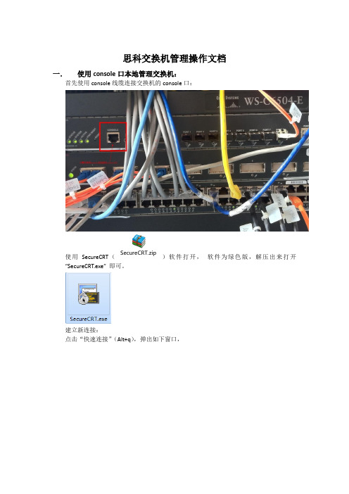
思科交换机管理操作文档一.使用console口本地管理交换机:首先使用console线缆连接交换机的console口:使用SecureCRT(SecureCRT.zip)软件打开,软件为绿色版,解压出来打开“SecureCRT.exe” 即可。
建立新连接:点击“快速连接”(Alt+q),弹出如下窗口,协议:选择Serial端口:根据实际端口选择,可在计算机管理设备管理器查看波特率:9600其他:按图中默认即可然后点击连接。
当用console口连接时,回车出现以下信息(也可能直接跳过这步):JXKFQ-6504 con0 is now availablePress RETURN to get started.接下来按回车键【Enter】,看到如下命令行:JXKFQ-6504>输入命令:enable然后按回车键,如下:JXKFQ-6504>enablePassword:此时输入用户密码:cisco如下:JXKFQ-6504#二.使用telnet远程管理交换机:使用局域网络连接交换机,创建Telnet会话:点击“快速连接”(Alt+q),弹出如下窗口,协议:Telnet主机名:输入交换机的管理地址其他:如上图默认即可然后点击连接。
1y18w: %IP-4-DUPADDR: Duplicate address 10.120.214.253 on Vlan213, sourced by 00ff.007b.c85d247Trying 10.120.215.247 ... OpenUser Access VerificationPassword:输入交换机Telnet密码:ciscoJXKFQ-3550-1>enablePassword:输入交换机管理密码:ciscoJXKFQ-3550-1#注:各交换机密码都为cisco三.交换机配置解析:1.配置模板:conf tenab sec ciscohostna JXKFQ-3550-1vtp mode transparentvlan 213no shint vlan 213ip add 10.120.215.247 255.255.255.0no shexitint ran f0/1 - 24swit mo accswit acc vlan 213int ran g0/1 - 2swit mo accswit acc vlan 213exitline vty 0 4pass ciscologinexitservice password-enip default-g 10.120.215.2532.操作命令解析:常用命令示例:1.关闭f0/1端口:Switch>Switch>enSwitch#conf tEnter configuration commands, one per line. End with CNTL/Z.Switch(config)#int f0/1Switch(config-if)#shutdown%LINK-5-CHANGED: Interface FastEthernet0/1, changed state to administratively down2.启用f0/1端口:Switch>enSwitch#conf tEnter configuration commands, one per line. End with CNTL/Z.Switch(config)#int f0/1Switch(config-if)#no shutdown%LINK-5-CHANGED: Interface FastEthernet0/1, changed state to up%LINEPROTO-5-UPDOWN: Line protocol on Interface FastEthernet0/1, changed state to up3.更改端口速率(一般默认auto即可无需更改):Switch#conf tEnter configuration commands, one per line. End with CNTL/Z. Switch(config)#int f0/1Switch(config-if)#spSwitch(config-if)#speeSwitch(config-if)#speed ?10 Force 10 Mbps operation100 Force 100 Mbps operationauto Enable AUTO speed configurationSwitch(config-if)#speed 10Switch(config-if)#4.查看mac地址表:sh mac-address-table在全局配置模式下Switch(config)#查看配置时,需要加一个do 命令,例如:do sh mac-address-table四.交换机常用命令注释:交换机的命令行操作模式主要包括:用户模式Switch>特权模式Switch#全局配置模式Switch(config)#端口模式Switch(config-if)#进入特权模式(Switch>en)进入全局配置模式(Switch#conf t)进入交换机端口视图模式(Switch(config)#int f0/1)返回到上级模式(exit)从全局以下模式返回到特权模式(end)帮助信息(如? 、co?、copy?)命令简写(如conf t)命令自动补全(Tab键)快捷键(ctrl+c 中断测试,ctrl+z 退回到特权视图)Reload重启。
思科路由器入门手册[1]
![思科路由器入门手册[1]](https://img.taocdn.com/s3/m/f925a591f121dd36a32d822a.png)
The following configuration command s cript was created:
hostname Router
enable secret 5 $1$W5Oh$p6J7tIgRMBOIKVXVG53Uh1
Ethernet0 unassigned NO unset up up
Serial0 unassigned NO unset up up
……… ……… … …… … …
然后,路由器就开始全局参数的设置:
Configuring global parameters:
1.设置路由器名:
Enter host name [Router]:
5. 网络命令
任务 命令
登录远程主机 telnet hostname|IP address
网络侦测 ping hostname|IP address
路由跟踪 trace hostname|IP address
6. 基本设置命令
任务 命令
全局设置 config terminal
设置访问用户及密码 username username password password
3) 设置接口的IP地址:
IP address for this interface: 192.168.162.2
4) 设置接口的IP子网掩码:
Number of bits in subnet field [0]:
Class C network is 192.168.162.0, 0 subnet bits; mask is /24
CISCO路由器系列文件
基本配置及命令解析
思科Cisco 200 系列智能型交换机管理指南
管理指南思科 200 系列智能型交换机管理指南目录目录2第 1章:使用入门1启动基于 Web 的交换机配置实用程序1交换机配置快速入门4接口命名约定5窗口导航5第 2章:查看统计信息9查看以太网接口9查看 Etherlike 统计信息10查看 802.1X EAP 统计信息11管理 RMON12第 3章:管理系统日志15设置系统日志设置15设置远程记录设置17查看内存日志18第 4章:管理系统文件20系统文件类型20升级/备份固件/语言22下载或备份配置或日志24查看配置文件属性27复制配置文件27DHCP 自动配置28第 5章:一般管理信息32交换机型号32系统信息33重启交换机35监控风扇状态和温度36定义空闲会话超时37Ping 主机37第 6章:系统时间39系统时间选项39SNTP 模式41配置系统时间41第 7章:管理设备诊断48测试铜缆端口48显示光纤模块状态50配置端口和 VLAN 镜像51查看 CPU 利用率和安全的核心技术52第 8章:配置发现54配置 Bonjour 发现54LLDP 和 CDP55配置 LLDP56配置 CDP73第 9章:端口管理80配置端口80设置基本的端口配置81配置链路聚合83配置绿色以太网89第 10章:智能端口95概述95什么是智能端口96智能端口类型96智能端口宏98宏失败和重置操作99智能端口功能如何运作100自动智能端口100错误处理103默认配置104与其他功能的关系和向后兼容性104常见智能端口任务104使用基于 Web 的界面配置智能端口106内置智能端口宏110第 11章:管理以太网供电设备122交换机上的 PoE122配置 PoE 属性124配置 PoE 功率、优先级和类别125第 12章: VLAN 管理128 VLAN128配置默认 VLAN 设置 130创建 VLAN131配置 VLAN 接口设置133定义 VLAN 成员关系134语音 VLAN137第 13章:配置生成树协议148 STP 模式148配置 STP 状态和全局设置149定义生成树接口设置150配置快速生成树设置152第 14章:管理 MAC 地址表154配置静态 MAC 地址154管理动态 MAC 地址155第 15章:配置组播转发157组播转发157定义组播属性160添加 MAC 组地址161添加 IP 组播组地址162配置 IGMP Snooping164MLD Snooping165查询 IGMP/MLD IP 组播组167定义组播路由器端口168定义“全部转发”组播169定义未注册的组播设置170第 16章:配置 IP 信息171管理与 IP 接口171配置 ARP181域名系统182第 17章:配置安全185定义用户186配置 RADIUS188配置管理访问验证190定义管理访问方法191配置 TCP/UDP 服务195定义风暴控制196配置端口安全197配置 802.1X199DoS 防护204第 18章:使用 SSL 功能206 SSL 概述206默认设置和配置206SSL 服务器验证设置207第 19章:安全敏感数据209简介209SSD 规则210SSD 属性214配置文件216SSD 管理通道220菜单 CLI 和密码恢复221配置 SSD221第 20章:配置服务质量224 QoS 功能和组件225配置 QoS - 一般226管理 QoS 统计信息2331使用入门本节介绍了基于 Web 的配置实用程序,具体包括以下主题:•启动基于 Web 的交换机配置实用程序•交换机配置快速入门•接口命名约定•窗口导航启动基于 Web 的交换机配置实用程序本节介绍了如何导航基于 Web 的交换机配置实用程序。
C20中文操作手册
C-20 PLUS 系列 气密检漏仪 使用说明书
共 85 页
6
Right arrow button 右键 用于菜单显示时移动光标。 (启动、停止及自动校准(需编程为输入)可以由遥控端子遥控执行)。 Security Protection密码保护 设置密码防止未经授权地改变设定值或执行校准。设 定的信息在27页。 仪器内部
Figure 2 Sentinel C-20 仪器内部 仪器内部没有任何操作者需要的部件,未经许可任何人不得打开仪器。
共 85 页
2
目录
第一章 -------------------------------------------------------------------------------------5 介绍 仪器全貌
第二章 -----------------------------------------------------------------------------------10 安装
气路的连接 在C-20左边只有一个进气口,真空型有另外一个进气口用于连接真空源,进气口 是1/4"FNPT,固定好仪器后,连接气源(或真空)到进气口,如图7之安装。为了降低 将来的维修机会,建议使用图6提及的0.3 和5.0微米的滤网,并且每一季更换一 次滤网。
共 85 页
12
Figure 7 Sentinel C-20的气路连接 测试接头在本体的底部是一个母的快速接头,利用1/4" FNPT软管公头来连接,建 议使用 Parker 1/4"或1/8" 2000 lbs 管子,因为可以在测试中忽略管子体积的变化 以及 Swagelok 或 Parker CPI ferrule type 接头,避免接头处漏气。针对Sentinel C-20-F 和 C-20-C 选用3/8" 或 1/2"的管子因为测试工件的体积较大,这样可以提 高其进气和排气的速度 。 在C-20仪器的快速接头允许操作者以手动的方式拆装,自检功能可以检出仪器本 身是否有内部泄漏,在拆装时要确认是否按下泄压按钮,并确认是否已经泄压完 毕,要不然会损坏胶圈导致漏气。自检找不出损坏胶垫漏气。 不要锁紧Sentinel C-20端的接头,本主体利用螺纹密封特殊加工,锁紧接头有可 能导致螺纹损坏,此种情况不在保修范围之内。
思科交换机配置维护手册

思科交换机配置维护手册目录一、端口配置1.1 配置一组端口当使用interface range命令时有如下的规则:•有效的组范围:o vlan从1 到4094o fastethernet槽位/{first port} - {last port}, 槽位为0o gigabitethernet槽位/{first port} - {last port},槽位为0o port-channel port-channel-number - port-channel-number, port-channel号从1到64•端口号之间需要加入空格,如:interface range fastethernet 0/1 – 5是有效的,而interface range fastethernet 0/1-5是无效的.•interface range命令只能配置已经存在的interface vlan•所有在同一组的端口必须是相同类别的。
见以下例子:Switch# configure terminalSwitch(config)# interface range fastethernet0/1 - 5Switch(config-if-range)# no shutdown以下的例子显示使用句号来配置不同类型端口的组:Switch# configure terminalSwitch(config)# interface range fastethernet0/1 - 3, gigabitethernet0/1 - 2 Switch(config-if-range)# no shutdown1.2 配置二层端口1.2.1 配置端口速率及双工模式Switch# configure terminalSwitch(config)# interface fastethernet0/3 Switch(config-if)# speed 10Switch(config-if)# duplex half1.2.2 端口描述1.2.3 配置三层口Catalyst 3750支持三种类型的三层端口: •SVIs: 即interface vlan•三层以太网通道口(EtherChannel)•.路由口:路由口是指某一物理端口在端口配置状态下用no switchport命令生成的端口所有的三层都需要IP地址以实现路由交换配置步骤如下:配置举例如下:Switch# configure terminalEnter configuration commands, one per line. End with CNTL/Z.Switch(config)# interface gigabitethernet0/2Switch(config-if)# no switchportSwitch(config-if)# ip address 192.20.135.21 255.255.255.0 Switch(config-if)# no shutdownSwitch(config-if)# endshow ip interface命令:Switch# show ip interface gigabitethernet0/2 GigabitEthernet0/2 is up, line protocol is upInternet address is 192.20.135.21/24Broadcast address is 255.255.255.255Address determined by setup commandMTU is 1500 bytesHelper address is not setDirected broadcast forwarding is disabled<output truncated>1.3 监控及维护端口1.3.1 监控端口和控制器的状态主要命令见下表:举例如下:Switch# show interfaces statusPort Name Status Vlan Duplex Speed TypeGi0/1 connected routed a-full a-100 10/100/1000Base TXGi0/2 wce server 20.20.2 disabled routed auto auto 10/100/1000Base TX Gi0/3 ip wccp web-cache notconnect routed auto auto 10/100/1000Base TX Gi0/4 notconnect routed auto auto 10/100/1000Base TX Gi0/5 notconnect routed auto auto 10/100/1000Base TX Gi0/6 disabled routed auto auto 10/100/1000Base TX Gi0/7 disabled routed auto auto 10/100/1000Base TX Gi0/8 disabled routed auto 100 10/100/1000Base TX Gi0/9 notconnect routed auto auto 10/100/1000Base TX Gi0/10 notconnect routed auto auto 10/100/1000Base TX Gi0/11 disabled routed auto auto unknownGi0/12 notconnect routed auto auto unknownSwitch# show interfaces fastethernet 0/1 switchportName: Fa0/1Switchport: EnabledAdministrative Mode: static accessOperational Mode: downAdministrative Trunking Encapsulation: dot1qNegotiation of Trunking: OffAccess Mode VLAN: 1 (default)Trunking Native Mode VLAN: 1 (default)Trunking VLANs Enabled: ALLPruning VLANs Enabled: 2-1001Protected: falseUnknown unicast blocked: disabledUnknown multicast blocked: disabledVoice VLAN: dot1p (Inactive)Appliance trust: 5Switch# show running-config interface fastethernet0/2Building configuration...Current configuration : 131 bytes!interface FastEthernet0/2switchport mode accessswitchport protectedno ip addressmls qos cos 7mls qos cos overrideend1.3.2 刷新、重置端口及计数器Clear命令目的clear counters [interface-id] 清除端口计数器.clear interface interface-id重置某一端口的硬件逻辑clear line [number | console 0 | vty number] 重置异步串口的硬件逻辑Note clear counters 命令只清除用show interface所显示的计数,不影响用snmp得到的计数举例如下:Switch# clear counters fastethernet0/5Clear "show interface" counters on this interface [confirm] ySwitch#*Sep 30 08:42:55: %CLEAR-5-COUNTERS: Clear counter on interface FastEthernet0/5by vty1 (171.69.115.10)可使用clear interface或clear line命令来清除或重置某一端口或串口,在大部分情况下并不需要这样做:Switch# clear interface fastethernet0/51.3.3 关闭和打开端口使用no shutdown命令重新打开端口.举例如下:Switch# configure terminalSwitch(config)# interface fastethernet0/5Switch(config-if)# shutdownSwitch(config-if)#*Sep 30 08:33:47: %LINK-5-CHANGED: Interface FastEthernet0/5, changed state to a administratively downSwitch# configure terminalSwitch(config)# interface fastethernet0/5Switch(config-if)# no shutdownSwitch(config-if)#*Sep 30 08:36:00: %LINK-3-UPDOWN: Interface FastEthernet0/5, changed state to up二、配置VLAN2.1 VLAN论述一个VLAN就是一个交换网,其逻辑上按功能、项目、应用来分而不必考虑用户的物理位置。
网络技术培训-思科路由器配置指南

参考带宽
(建议配置成ISP给你的 实际带宽)
RouterX(config-if)#bandwidth 64 RouterX(config-if)#exit
show interfaces
RouterX#show interfaces Ethernet0 is up, line protocol is up
81833 packets input, 27556491 bytes, 0 no buffer Received 42308 broadcasts, 0 runts, 0 giants, 0 throttles 1 input errors, 0 CRC, 0 frame, 0 overrun, 1 ignored, 0 abort 0 input packets with dribble condition detected 55794 packets output, 3929696 bytes, 0 underruns 0 output errors, 0 collisions, 1 interface resets 0 babbles, 0 late collision, 4 deferred 0 lost carrier, 0 no carrier 0 output buffer failures, 0 output buffers swapped out
Hardware is Lance, address is 00e0.1e5d.ae2f (bia 00e0.1e5d.ae2f) Internet address is 10.1.1.11/24 MTU 1500 bytes, BW 10000 Kbit, DLY 1000 usec, rely 255/255, load 1/255 Encapsulation ARPA, loopback not set, keepalive set (10 sec) ARP type: ARPA, ARP Timeout 04:00:00 Last input 00:00:07, output 00:00:08, output hang never Last clearing of "show interface" counters never Queueing strategy: fifo Output queue 0/40, 0 drops; input queue 0/75, 0 drops 5 minute input rate 0 bits/sec, 0 packets/sec 5 minute output rate 0 bits/sec, 0 packets/sec
思科网络网管员指南

思科网络网管员指南第一章:设备管理方式管理系统文件管理系统文件基本上就是备份IOS镜像,配置文件等,一般使用TFTP或者FTP方式.TFTP基于UDP端口69,是一个简化的FTP协议.但是有一些权限比如缺乏安全性,有16MB文件大小的限制,使用UDP缺乏可靠性,新的IOS版本开始支持FTP,TCP端口21的传输协议,尽管也是类似Telnet的明文传输.注意:关于TFTP传输文件大小限制的讨论参见我的blog.Windows下的TFTP Server: Solarwind’s TFTP, 3Com TFTP DaemonGUI界面很简单的配置Linux下的TFTP ServerLinux下有内置的TFTP服务器,由xinetd或者inetd来控制.首先要修改inetd.conf指定你的TFTP目录.创建相应的目录和修改权限(mkdir /tftpboot, chmod 666 /tftpboot, chown nobody /tftpboot),创建文件(linux下的tftpd 有安全特性,必须要求所要传输的文件要存在于TFTP目录: touchrouter-config.cfg, chmod a+wr *),重启进程生效(/etc/inetd restart). IOS下的TFTP Server思科设备可以配置为TFTP Server来共享自己的IOS镜像.例子如下:Router#show flashPCMCIA flash directory:File Length Name/status1 10685392 /c1600-osy56i-l.121-16.bin[10685456 bytes used, 6091760 available, 16777216 total]16384K bytes of processor board PCMCIA flash (Read ONLY)Router#conf tRouter(config)#tftp-server flash:c1600-osy56i-l.121-16.binWindows下的FTP服务器:IIS这个有点复杂了..暂略.Linux 下的FTP 服务器:vsFTP,WUFtp,Proftp Vsftp 安装略,修改vsftpd.conf注意:只要记住copy 是源文件地址到目标文件地址的命令格式就可以了.为了解决FTP 的安全传输的问题,从12.2T 开始思科开始支持Secure Copy Protocol (SCP).通过配置ip scp server enable 来实现,详细解释参考思科网站.第二章 网络连通性介绍系统内置的一些测试工具比如Ping,Traceroute,whois,nslookup 等.尽管很简单很基础,但是里面还是有些值 得注意的问题,还将介绍一个小案例.网络连通性基本测试工具Ping 可以说是再平常不过的测试工具了,主要用来测试两点间的连通性,Round-Trip 的延迟和丢包率等. Windows 下Ping 的使用 Ping /?可以显示ping 的各种参数,不过我相信没几个人看完这些参数的.下面介绍几个有用的参数.Ping 缺省认为1000毫秒为超时,使用-w 参数可以修改此超时时间,比如在有些无线环境中Roundtrip 时间就很长,如果使用缺省值ping 就可能会出现Request timed out 情况.-t 参数可以保持持久ping,Ctrl-Break 可以保持命令继续执行看当前的汇总,Ctrl-c 则是停止命令. -a 解析主机名-f用来设置DF位,-l用来设置数据载荷的大小.通常用来检测网络的MTU.注意:MTU为最大传输单元,不同的网络情况此值都有不同,特别是在配置VPN的时候很重要,因为数据头有很多额外的开销.如果用户数据包大于MTU就会在传输中被分段.Windows下缺省Ping数据包大小为56字节,一般不会出现MTU问题,但是用户应用数据一般就不会只有这么小,所以要使用-l来测试.注意:MTU是数据载荷大小和IP头大小的和,而在windows下ping的IP头为28字节,所以最终的MTU大小应为-l的值和28之和.Linux下Ping的使用Linux下ping跟windows下略有不同,缺省就是持续ping,-c参数可以指定ping 的次数.类似于windows的MTU问题,-M do是设置DF位,-c来设置数据载荷的大小.注意:Linux下ping的IP头为28字节.IOS下ping的使用IOS下的Ping在用户模式和特权模式下都有,相应的权限不同,除了可以针对IP 协议以外,也支持IPX,AppleTalk等协议.缺省是5个包,每个包的大小为100字节,超时为2秒,使用流出端口的地址作为包的源地址.没有持续ping的参数,可以变相的通过将ping的次数设为最大值9999999来实现.可以通过组合键Ctrl-Shift-6加x来实现ping的中断.由于特权模式下的ping参数是通过对话的形式实现,所以不需要过多介绍.注意:在平常的网络中可能由于安全的限制只能使用特定的源地址进行ping(比如设备的loopback地址),而缺省这里使用的流出端口地址可能是被禁止的,所以需要通过特权模式的ping来设定源地址来避免这种情况.Ping的变种Fping:一般ping只能一次测试一个主机,fping可以同时测试多个主机.基于linux的,可以在这里下载.Hping:ping是基于ICMP Echo Request的.而有些网络的防火墙禁止了ICMP,Hping可以提供基于TCP,UDP等协议来测试远端主机的连通性.也是基于linux的,在此下载.SmokePing:此软件可以给你图形化的显示网络性能比如延时,丢包率等等.在此下载.Ping的测试步骤(这个好像CCNA爱考)1.Ping 127.0.0.1 确认本地的TCP/IP堆栈工作正常2.Ping 本机IP地址确认网卡和链路工作正常3.Ping 网络网关确认网关之间路由正常4.Ping 远端主机确认和远端主机连通TraceRoute使用TTL的特性来检查网络的连通性,提供了网络路径等Ping所不能提供的更详细排错信息.Windows下tracert的使用Windows下是基于ICMP Echo Request协议的,可以使用-d参数来禁止地址翻译,-h指定最大跳数,-w指定超时时间.Linux下traceroute的使用Linux下是基于UDP协议(当然也可以使用-I参数来恢复使用ICMP协议),一般第一个包使用端口33434,后面的包的端口依次增加来减少被禁止的可能,当然此端口可以使用-p参数来修改,-n禁止地址解析增加输出速度.IOS下traceroute的使用IOS下的traceroute跟ping比较类似也是分不同模式,也通过对话选择形式进行参数调整.缺省3个包使用UDP端口33434,超时时间为3秒,使用流出端口的地址作为包的源地址.网络连通性高级测试工具尽管有很多网络工具可以供网管使用,这里仅仅介绍一些系统内置的工具. Whois:提供域名信息的工具,linux内置,尽管现在也有win下的版本Nslookup:针对DNS服务器的查询域的MX,A,CNAME记录.win和linux下都可以使用,set query=all,或者mx等可以查询全部或者部分的信息.在Linux下还有一个类似的dig命令,提供的输出更多,更易懂,并且所有的参数可以通过一个命令行完成,方便制作脚本.常用命令格式为dig @dns-server targetdomain query-type.Netstat是一个可以在win和linux下使用的获得端口,连接,路由等网络信息的工具.Win下的netstat:不加参数显示当前活动的TCP连接,后面可以加数字(秒)得到不停刷新的信息.-n显示地址而不是域名,-a显示所有的连接,在xp和2003还有一个新的-o的参数可以显示相应连接的PID(process identification).-e显示接口的摘要信息,-o显示协议的摘要信息.-r显示系统路由信息,相同于route print命令.Linux下的netstat:不加参数会显示当前活动的所有连接包括Unix Sockets信息-atuwp参数可以去掉socket信息,-t参数显示当前活动的TCP连接,-c可以周期性的自动刷新.-n等同于win下的.-i显示接口的摘要信息,-s显示协议的摘要信息,-r显示路由表,相同于route命令.Nbstat:win下的Arp:Win和Linux下查询MAC地址和IP地址映射信息的工具.-a显示arp表,-s 指定一个静态的映射,-d删除一个映射.案例一般情况下我们认为只要能Ping通就代表网络没有问题了,对于有少量的丢包也认为是正常现象,其实有时候问题就隐藏在这些小量丢包的后面.有一个企业网络,客户老是抱怨使用改企业的内部应用老是有问题,而内部人员则没有发现什么问题.从内部ping也很正常,后来尝试持续ping边缘路由器,发现虽然能通但是隔30秒就会time out一两次.开始被认为是正常现象,后来研究发现ping 使用的ICMP的包,而对ICMP包的处理在路由器上的优先级是很低的,如果路由器出现CPU负荷过高就会不相应ICMP,进而导致time out.去边缘路由器show cpu 一看果然CPU利用率90%,检查配置发现没有开启ip route-cache,并且路由器每隔30秒会收到上游发送的BGP路由,从而导致路由器停止处理数据包,出现服务无法相应的状况.开启路由器快速交换后解决问题.小小的Ping发现了网络大问题.第四章Syslog服务讲述Syslog的架构和如何在思科的网络环境下部署Linux和Win下的ang=EN-US>syslog服务器,以及相应思科设备的配置.Syslog简介Syslog协议允许设备向消息收集器发送相应的事件信息.使用UDP端口514,不需要确认,大小为1024字节.包含Facility,Severity,Hostname,Timestamp,Message五种信息.Facility是syslog对信息源的大致分类,比如该事件来源于操作系统,进程等,用整数表示.其中16-17的local use可以为哪些没有被明确定义的进程或者应用所使用,通常思科IOS设备,CatOS交换机,VPN3000使用Facility Local7发送syslog信息,PIX防火墙使用local4,当然这些缺省值是可以修改的.Severity 信息源或者1位数字进行分类.Hostname 设备名或者IP地址,如果多接口使用传送信息端口的IP地址. Timestamp 时间戳是本地时间,IOS允许添加时区信息,前面加个特殊字符比如*,格式如下: MMM DD HH:MM:SS Timezone *.Message 信息.Syslog服务器的部署内置syslogd的配置/etc/syslog.conf文件控制syslogd的配置.里面有根据facility和severity 来定义的规则,格式为facility.severitydestination-file-path,里面缺省的记录系统的信息不需要更改.对于思科设备来说facility从local0到local7,severity为前面提到的debug,info,notice,warning,err,crit,alert,emerg和none.为了方便定义规一个复杂的例子如下:local6.*;local6.!=err /var/log/allexcepterror.log 写入所有facility为local6的信息到all*.log文件,只排除severity为err的信息缺省情况下syslogd只能接收来自本地的syslog信息,如果要接收远端的syslog信息,启动的时候要加上-r选项配置基于linux的syslog-ng服务器由于内置syslogd的有facility分类笼统,信息过滤弱等缺陷,推荐使用syslog-ng来替代.去该网站下载安装后通过修改/etc/syslog-ng文件来进行软件的配置.该文件包含5个部分:options,source,destination,filter和log.Options 定义全局选项,格式为options { option1(value);option2(value); ... };Source 定义守护进程收集信息的源,格式为source identifier{ source-driver(params); source-driver(params); ... };Destination 定义所收集信息经过过滤后保存的地方,格式为destination identifier { destination-driver(params); destination-driver(params);例子destination hosts { file("/var/log/host/$DATE" create_dirs(yes)); }; 按照日期来保存文件,如果没有相应的目录为自动创建.Filter 定义过滤规则,格式为filter identifier { expression; };Log 把source,filter,destination合并,实现来自某个source的信息符合特定的filter后送到所定义的destination.格式为log { source(s1);source(s2); ...filter(f1); filter(f2); ...destination(d1); destination(d2); ...flags(flag1[, flag2...]); };配置基于Windows的syslog服务器Kiwi Syslog是一个免费的图形化syslog服务软件,安装配置比较简单.配置思科设备对syslog的支持路由器下syslog支持的配置配置示例:Router(config)#logging 192.168.0.30 配置syslog服务器地址,可以定义多个Router(config)#service timestamps debug datetime localtime show-timezone msecRouter(config)#service timestamps log datetime localtime show-timezone msec syslog信息包含时间戳Router(config)#logging facility local3 定义facility级别,缺省为local7,可以设置从local0到local7Router(config)#logging trap warning 定义severity级别缺省为infor级别Router(config)#endRouter#show loggingSyslog logging: enabled (0 messages dropped, 0 flushes, 0 overruns)Console logging: level debugging, 79 messages loggedMonitor logging: level debugging, 0 messages loggedBuffer logging: disabledTrap logging: level warnings, 80 message lines loggedLogging to 192.168.0.30, 57 message lines logged交换机下syslog支持的配置配置示例:Console> (enable) set logging timestamp enable 定义信息包含日期戳Console> (enable) set logging server 192.168.0.30 指定服务器地址,最多可以指定3个Console> (enable) set logging server facility local4 定义facility级别,缺省为local7,Console> (enable) set logging server severity 4 定义severity级别除了前面提到的路由器上的severity级别以外还有一些交换机特有的Console> (enable) set logging server enable 启用syslog服务Console> (enable) show loggingLogging buffered size: 500timestamp option: enabledLogging history size: 1Logging console: enabledLogging server: enabled{192.168.0.30}server facility: LOCAL4server severity: warnings(4Current Logging Session: enabledFacility Default Severity Current Session Severity------------- ----------------------- ------------------------cdp 3 4drip 2 4PIX防火墙下syslog支持的配置配置示例:Firewall(config)# loggin timestamp 定义信息包含日期戳Firewall(config)# logging host 192.168.0.30 服务器地址,可以指定以udp或者tcp来发送信息,对于思科的PIX FW syslog 软件只发送tcp.Firewall(config)# logging facility 21 定义facility级别,防火墙使用两位字符,local0对应16,依次类推,缺省为20也就是local4Firewall(config)# logging trap 7 定义severity级别,7为debug,0为emer,1为alert.Firewall(config)# logging on 启用syslogFirewall(config)# no logging message 111005 抑制特定的syslog信息Firewall(config)# exitFirewall# show loggingSyslog logging: enabledFacility: 21Timestamp logging: enabledStandby logging: disabledConsole logging: disabledMonitor logging: disabledBuffer logging: disabledTrap logging: level debugging, 6 messages loggedLogging to inside 192.168.0.30History logging: disabledDevice ID: disabledVPN Concentrator下syslog支持的配置在web管理界面下Configuration > System > Events > Syslog Servers通过add来增加syslog server的地址和facility级别. Configuration > System > Events > General下通过severity to syslog的下拉菜单选择发送信息的serverity级别.然后保存修改.。
视频会议系统思科C系列操作手册

视频会议系统思科C系列操作⼿册C系列产品操作⼿册⼀、连线和开机 (3)⼆、TRC5遥控器使⽤说明 (3)三、会议中的操作 (7)四、如何进⾏系统升级 (11)五、注意事项 (11)六、常见问题和解决办法 (12)⼀、连线和开机将C系列产品正确连接(参看上图,每个产品均包含背板连接说明),确保设备电源已经并打开,以及,遥控器电池电量充⾜。
拿起遥控器或者按下遥控器上的任意按键,C系列产品会从待机状态恢复到显⽰状态。
⼆、TRC5遥控器使⽤说明TRC5腾博C系列遥控器主要由三个区域构成,最上⼀排为可⾃定义的快捷按键;中间区域为功能区;最下⾯的拨打和数字键盘区类似⼿机功能,⽤来拨号和挂断会议。
如下图所⽰:1、快捷按键区,对应在显⽰画⾯下⾯5个功能按键2、功能按键区,主要按键作⽤如下所⽰:3、拨号和数字键盘使⽤⽅法,如下图所⽰:在输⼊号码时,会⾃动以数字来进⾏录⼊,如下图所⽰:若进⾏⽂字输⼊,会⾃动切换为英⽂状态,若需要变换输⼊的类型(123/abc/ABC),可以通过快速点击快捷键(最左⾯按钮)来切换,以实现最左边的功能选项。
中间的功能项(对应第⼆个快捷键)为调⽤特殊字符按键,右边的功能项为保存改呼叫号码。
快速切换⽅法:按1下“#a/A”键,进⾏英⽂⼤⼩写的切换;长按下“#abc/123”可以进⾏⼩写字母和数字的切换;在⽂字输⼊模式,按“0”键进⾏空格的输⼊;在⽂字输⼊模式,按“1”键两次,可以输⼊@字符;在数字输⼊模式,按“*”键,可以输⼊“.”字符;删除上⼀个字符,按“c”键。
4、使⽤电话本点击遥控器上“号码本”按键,可以调出搜索菜单,在该菜单⾥输⼊要查询的⼈名单⾸字母,会⾃动匹配相应的联系⼈名称。
在号码本中新建⼀个联系⼈,可以在“联系⼈”菜单上,点击“确定”按钮,这时会弹出快捷菜单按钮,第三个功能菜单为添加新的联系⼈,点击遥控器上对应的快捷按键可得到新建联系⼈操作界⾯:输⼊内容,保存即可。
5、通讯记录在最近通话记录中,可保留曾经的呼⼊或呼出记录,注意箭头⽅向,以表⽰呼出还是呼⼊。
Cisco网络设备配置和管理入门教程
Cisco网络设备配置和管理入门教程CHAPTER 1: Introduction to Cisco Networking DevicesCisco networking devices are widely used in various industries for establishing and managing computer networks. These devices enable organizations to connect and communicate effectively with their internal and external stakeholders. In this chapter, we will introduce the basics of Cisco networking devices and their importance in modern networking.1.1 What is a Cisco Networking Device?A Cisco networking device refers to any hardware that is manufactured by Cisco Systems, Inc., a leading provider of networking solutions. These devices include routers, switches, firewalls, and access points, among others. They are designed to facilitate the transmission of data and the establishment of connections between different network devices.1.2 Importance of Cisco Networking DevicesCisco networking devices play a crucial role in the functioning of modern computer networks. They provide several key benefits, including:1.2.1 Connectivity: Cisco devices enable the establishment of connections between multiple devices within a network, allowing data to be transmitted and received efficiently.1.2.2 Security: Cisco devices integrate advanced security features, such as firewalls and intrusion prevention systems, which safeguard networks against unauthorized access and potential threats.1.2.3 Scalability: Cisco devices are scalable, meaning they can handle increasing network traffic and accommodate additional devices as the network expands.1.2.4 Reliability: Cisco devices are known for their reliability and uptime, ensuring uninterrupted network connectivity and minimizing downtime.CHAPTER 2: Configuring Cisco Networking DevicesConfiguring Cisco networking devices is a critical aspect of their management. Proper configuration enables these devices to function efficiently and meets the specific requirements of a network. In this chapter, we will explore the essential steps involved in configuring Cisco networking devices.2.1 Accessing the Device InterfaceTo configure a Cisco networking device, you need to access its interface. This can be achieved through various methods, including a console cable, Telnet, SSH, or web-based interfaces. Each method has its own advantages and security considerations.2.2 Basic Configuration StepsOnce you have accessed the device interface, you can begin configuring the Cisco networking device. The basic configuration steps include:2.2.1 Setting the hostname: Assigning a unique name to the device for identification purposes.2.2.2 Configuring IP addresses: Assigning IP addresses to the device interfaces for proper network connectivity.2.2.3 Enabling routing: Configuring routing protocols to facilitate the exchange of network traffic between different networks.2.2.4 Configuring security settings: Implementing security measures, such as passwords and access control lists, to protect the device and the network.CHAPTER 3: Managing Cisco Networking DevicesManaging Cisco networking devices involves ongoing tasks to ensure their optimal performance and security. In this chapter, we will discuss various management tasks and techniques.3.1 Device MonitoringTo effectively manage Cisco networking devices, it is crucial to monitor their performance and status regularly. This can be achieved using tools such as Simple Network Management Protocol (SNMP) or Cisco Prime Infrastructure, which provide valuable insights into device health, network traffic, and potential issues.3.2 Firmware UpgradesRegular firmware upgrades are essential to keep Cisco devices up-to-date with the latest features, bug fixes, and security patches. These upgrades can be performed through the device's web interface or command-line interface, following documented procedures provided by Cisco.3.3 Backup and RestoreTo ensure the safety of network configurations and device settings, regular backups should be performed. Cisco devices offer various methods, such as using TFTP (Trivial File Transfer Protocol) or SCP (Secure Copy Protocol), to back up configuration files, allowing for easy restoration in case of device failure or configuration errors.CHAPTER 4: Troubleshooting Cisco Networking DevicesTroubleshooting is an integral part of managing Cisco networking devices. In this chapter, we will discuss common issues that may arise and the steps to address them effectively.4.1 Identifying connectivity issues: When a device fails to connect to the network, troubleshooting involves verifying physical connections, verifying IP configurations, and utilizing network diagnostic tools, such as ping and traceroute.4.2 Analyzing logs: Cisco devices generate logs that provide valuable information about their operation and potential issues.Analyzing these logs can help identify and resolve problems, such as hardware failures or configuration conflicts.4.3 Performing packet captures: Packet captures allow network administrators to analyze network traffic in detail and identify any abnormalities, such as excessive broadcast storms or network congestion.CONCLUSIONCisco networking devices are crucial components in modern computer networks. Understanding the basics of their configuration, management, and troubleshooting is essential for network administrators and IT professionals. This introductory tutorial provides a foundation to further explore the intricacies of Cisco networking devices and enhance networking knowledge and skills.。
思科 200 系列智能交换机快速入门指南说明书
Quick Start GuideCisco Small Business200 Series Smart SwitchesWelcomeThank you for choosing the Cisco 200 Series Smart Switch, a Cisco Small Business network communications device. This device is designed to be operational right out-of-the-box as a standard bridge. In the default configuration, it will forward packets between connecting devices after powered up.Before you begin installing the switch, make sure you have all of the package contents available, access to the Cisco Small Business 200 Series Smart Switch Administration Guide, and a PC with a web browser for using web-based system management tools.Package Contents•Cisco 200 Series Smart Switch.•Rackmount Kit.•Power Cord or Adapter•This Quick Start Guide.•Product CD.This guide will familiarize you with the layout of the smart switch and describe how to deploy the device in your network. For additional information, see /smb.Mounting the Cisco Switch1There are two ways to mount the switch:•Set the switch on a flat surface.•Mount the switch in a standard rack (1 rack unit high).Do not mount the device in a location where any of the following conditions exist:High Ambient Temperature—The ambient temperature must notexceed 104 degrees Fahrenheit (40 degrees Centigrade).N OTE Some switches have a higher temperature rating. The SG200-10FP, SF200-24FP, SG200-26FP, and SG200-50FP are rated at 113 degrees Fahrenheit (45 degrees Centigrade).Reduced Air Flow—Both side panels must be unobstructed to prevent overheating.2200 Series Smart Switches200 Series Smart Switches 3Mechanical Overloading —The device must be level, stable, and secure to prevent it from sliding or shifting out-of-position.Circuit Overloading —Adding the device to the power outlet must not overload that circuit.Rack-Mount PlacementS TEP 1Remove the four screws from each side near the front of the switch.Retain the screws for re-installation. (Do not remove the four screws from each side near the back of the switch.)S TEP 2Place one of the supplied spacers on the side of the switch so thefour holes of the spacers align to the screw holes. Place a rackmount bracket next to the spacer and reinstall the four screwsremoved in Step 1.N OTE If your screws are not long enough to reattach the bracket with the spacer in place, attach the bracket directly to the case without the spacer.S TEP 3Repeat Step 2 for the other side of the switch.S TEP 4After the mounting hardware has been securely attached, the switch is now ready to be installed into a standard 19-inch rack.C AUTION For stability, load the rack from the bottom to the top, with the heaviest devices on the bottom. A top-heavy rack is likely tobe unstable and might tip over.Connecting Network Devices2T o connect the smart switch to the network:S TEP1Connect the Ethernet cable to the Ethernet port of a computer, printer, network storage, or other network device.S TEP2Connect the other end of the Ethernet cable to one of the numbered smart switch Ethernet ports.The LED of the port lights if the device connected is active. Refer toFeatures of the Cisco Small Business Smart Switch, page9 fordetails about the different ports and LEDs on each switch.S TEP3Repeat Step 1 and Step 2 for each device you want to connect to the smart switch.N OTE Cisco strongly recommends using Cat5 or better cable for Gigabit connectivity. When you connect your network devices, do not exceed the maximum cabling distance of 100 meters (328 feet). It can take up to one minute for attached devices or the LAN to be operational after it is connected. This is normal behavior.Power over Ethernet ConsiderationsW ARNING The switch is to be connected only to PoE networks without routing to the outside plant.If your switch is one of the Power over Ethernet (PoE) models, consider the following power requirement:4200 Series Smart Switches200 Series Switches with Power Over EthernetModel PowerDedicated toPoE Number ofPortsSupportingPoEPoEStandardSupportedSG200-10FP62 Watts1—8802.3afSF200-24P100 Watts1—6 and13—18802.3afSF200-24FP180 Watts1—24802.3afSF200-48P180 Watts1—12 and25—36802.3afSG200-26P100 Watts1—6 and13—18802.3afSG200-26FP180 Watts1—24802.3afSG200-50P180 Watts1—12 and25—36802.3afSG200-50FP375 Watts1—48802.3af200 Series Smart Switches5C AUTION Consider the following when connecting switches capable ofsupplying PoE:The PoE models of the switches are PSE (Power SourcingEquipment) that are capable of supplying DC power toattaching PD (Powered Devices). These devices include VoIPphones, IP cameras, and wireless access points. The PoEswitches can detect and supply power to pre-standardlegacy PoE Powered Devices. Due to the support of legacyPoE, it is possible that a PoE switch acting as a PSE maymistakenly detect and supply power to an attaching PSE,including other PoE switches, as a legacy PD.Even though PoE switches are PSE, and as such should bepowered by AC, they could be powered up as a legacy PDby another PSE due to false detection. When this happens,the PoE switch may not operate properly and may not beable to properly supply power to its attaching PDs.T o prevent false detection, you should disable PoE on theports on the PoE switches that are used to connect to PSEs.You should also first power up a PSE device beforeconnecting it to a PoE switch. When a device is being falselydetected as a PD, you should disconnect the device from thePoE port and power recycle the device with AC powerbefore reconnecting its PoE ports.Configuring the Cisco Small Business 3Smart SwitchBefore You BeginVerify the managing computer requirements in the product release notes. Accessing and Managing Your Switch Using the Web-Based InterfaceT o access the switch by using the web-based interface, you must know the IP address the switch is using. The switch uses the factory default IP address of 192.168.1.254 by default.6200 Series Smart SwitchesWhen the switch is using the factory default IP address, the System LED flashes continuously. When the switch is using a DHCP server-assigned IP address or an administrator has configured a static IP address, the System LED is on solid (DHCP is enabled by default).N OTE If you are managing the switch through a network connection and the switch IP address is changed, either by a DHCP server or manually, your access to the switch will be lost. You must enter the new IP address the switch is using into your browser to use the web-based interface.T o configure the smart switch:S TEP1Power on the computer and the switch.S TEP2Set the IP configuration on your computer.a.If the switch is using the factory default IP address of192.168.1.254, you must chose an IP address for the computerin the range of 192.168.1.1—192.168.1.253 that is not already inuse.b.If the IP addresses is assigned by a DHCP server, make surethe DHCP server is running and can be reached from theswitch and the computer. It might be necessary to disconnectand reconnect the devices for them to discover their new IPaddresses from the DHCP server.N OTE Details on how to change the IP address on your computerdepend upon the type of architecture and operating system you are using. Use the computer Help and Support functionality to search for “IP Addressing.”S TEP3Open a Web browser window. If you are prompted to install an Active-X plug-in when connecting to the device, follow theprompts to accept the plug-in.S TEP4Enter the switch IP address in the address bar and press Enter. For example, http://192.168.1.254.The Switch Login Page displays.S TEP5Enter the default login information:•Username is cisco•Default password is cisco (passwords are case sensitive)S TEP6If this is the first time that you have logged on with the default username and password, the Change Password Page opens. Therules for constructing a new login and password are displayed onthe page. Enter a new administrator password and click Apply.200 Series Smart Switches7C AUTION Make sure that any configuration changes made are saved tothe Startup configuration before exiting from the web-basedinterface by clicking on the Save icon. Exiting before yousave your configuration will result in all current changesbeing lost the next time the switch is rebooted.The Getting Started window displays. You are now ready to configure the switch. Refer to the Cisco 200 Series Smart Switch Administration Guide for further information.Troubleshoot Your ConnectionIf you cannot access your switch from the web-based interface, the switch may not be reachable from your computer. You can test network connections by using ping on a computer running Windows:S TEP1Open a command window by using Start > Run and enter cmd.S TEP2At the Command window prompt enter ping and the smart switch IP address. For example ping 192.168.1.254 (the default IP addressof the smart switch).If you can reach the switch, you should get a reply similar to thefollowing:Pinging 192.168.1.254 with 32 bytes of data:Reply from 192.168.1.254: bytes=32 time<1ms TTL=128 If you cannot reach the switch, you should get a reply similar to thefollowing:Pinging 192.168.1.254 with 32 bytes of data:Request timed out.Possible Causes and ResolutionsNo Power:Power up the switch and your computer if they are turned off.Bad Ethernet connection:Check the LEDs for proper indications. Check the connectors of the Ethernet cable to ensure they are firmly plugged into the switch and your computer.8200 Series Smart SwitchesWrong or conflicting IP address:Make sure that you are using the correct IP address of the switch. You can verify the current IP address of the switch with your networkadministrator. The System LED provides an indication of where theswitch received the IP address, see Section 4 for details.Make sure that no other device is using the same IP address as the switch.No IP route:If the switch and your computer are in different IP subnets, you need one or more routers to route the packets between the two subnets. Unusually long access time:Due to the spanning tree loop detection logic, adding new connections might take 30 to 60 seconds for the affected interfaces and/or LAN to become operational.Features of the Cisco Small Business4Smart SwitchThis section describes the exterior of the smart switches including ports, LEDs, and connections. Not all models will have all of the features described.PortsRJ-45 Ethernet Ports—Use these ports to connect network devices, such as computers, printers, and access points, to the switch.•SFP (if present)—The small form-factor pluggable (SFP) ports are connection points for modules, so the switch can link to other switches.These ports are also commonly referred to as miniGigaBit Interface Converter (miniGBIC) ports. The term SFP will be used in this guide.•SFP ports are compatible with Cisco modules MGBT1, MGBSX1, MGBLH1, MGBLX1, MGBBX1, MFELX1, MFEFX1, and MFEBX1, as well as other brands of modules.•Some SFP interfaces are shared with one other RJ-45 port, called a combo port. When the SFP is active, the adjacent RJ-45 port isdisabled.•The LEDs of the corresponding RJ-45 port flashes green to respond to the miniGBIC interface traffic.200 Series Smart Switches9LEDsSystem LED—(Green) Lights steady when the switch is powered on, and flashes when booting, performing self tests, and acquiring an IP address. If the LED flashes amber, the switch has detected a hardware failure.LINK/ACT LED—(Green) Located on the left of the port. Lights steady when a link between the corresponding port and another device is detected. Flashes when the port is passing traffic.N OTE The System and LINK/ACT LEDs are on each model of the switch.The following LEDs are only present on switch models that have those capabilities:PoE (if present)—(Amber) Located on the right of the port. Lights steady to indicate that power is being supplied to a device attached to the corresponding port.100M LED (if present)—(Green) Located on the right of the port. Lights steady when another device is connected to the port, is powered on, and a 100Mbps link is established between the devices. When the LED is off, the connection speed is under 100Mbps or nothing is cabled to the port.Gigabit LED (if present)—(Green) Located on the right of the port. Lights steady when another device is connected to the port, is powered on, and a 1000Mbps link is established between the devices. When the LED is off, the connection speed is under 1000Mbps or nothing is cabled to the port.SFP (if present)—(Green)Located on the right of a GE port. Lights steady when a connection is made through the shared port. Flashes when the port is passing traffic.Additional FeaturesThe switch might also have a reset button. The switch can be reset by inserting a pin or paper clip into the reset opening. See “Returning the Device to the Factory Default Settings” for details.Back PanelThe power port is located on the back panel of the smart switch.10200 Series Smart SwitchesReturning the Device to the Factory5Default SettingsT o use the Reset button to reboot or reset the smart switch, do the following:•T o reboot the smart switch, press the Reset button for less than 10 seconds.•T o restore the smart switch configuration to the factory default settings:1.Disconnect the smart switch from the network or disable all DHCPservers on your network.2.With the power on, press and hold the Reset button for more than10 seconds.200 Series Smart Switches11Where to Go From HereSupportCisco Small Business SupportCommunity/go/smallbizsupportCisco Small Business Supportand Resources/go/smallbizhelpCisco Small Business SupportCenter (SBSC) Contacts/go/sbscCisco Small Business Firmware Downloads /go/smallbizfirmwareSelect a link to download firmware for Cisco Small Business Products. No login is required.Product DocumentationCisco Small Business SmartSwitches/go/200switchesRegulatory, Compliance, and Safety Information /en/US/docs/switches/lan/ csb_switching_general/rcsi/Switch_RCSI.pdfWarranty Information /go/warrantyCisco Small BusinessCisco Partner Central for SmallBusiness (Partner LoginRequired)/web/partners/sell/smbCisco Small Business Home /smb612200 Series Smart SwitchesAmericas HeadquartersCisco Systems, Inc.170 West T asman DriveSan Jose, CA 95134-1706USASmall Business Support US: 1-866-606-1866Small Business Support Global Contact NumbersCisco and the Cisco logo are trademarks or registered trademarks of Cisco and/or its affiliates in the U.S. and other countries. To view a list of Cisco trademarks, go to this URL: /go/trademarks. Third-party trademarks mentioned are the property of their respective owners. The use of the word partner does not imply a partnership relationship between Cisco and any other company. (1110R)© 2010-2013 Cisco Systems, Inc. All rights reserved.78-19501-01B0。
思科路由器基本配置详细教程

思科路由器基本配置详细教程思科路由器配置过程还是比较复杂的,需要考虑的因素很多,特别在安全方面。
其实没必要把路由器想的那么复杂,其实路由器就是一个具有多个端口的计算机,只不过它在网络中起到的作用与一般的PC不同而已。
如何才能真正的做好思科路由器的配置工作?下面,我们就针对这个问题详细的介绍一下。
一、思科路由器的简介所有思科路由器配置的IOS都是一个嵌入式软件体系结构。
和普通计算机一样,路由器也需要一个操作系统,思科把这个操作系统叫作思科互联网络操作系统,也就是我们知道的IOS。
思科IOS软件提供以下网络服务:可扩展的网络结构、基本的路由和交换功能、可靠和安全的访问网络资源。
思科命令行界面(CLI)用一个分等级的结构,这个结构需要在不同的模式下来完成特定的任务。
例如配置一个路由器的接口,用户就必须进入到路由器的接口配置模式下,所有的配置都只会应用到这个接口上。
每一个不同的配置模式都会有特定的命令提示符。
EXEC为IOS软件提供一个命令解释服务,当每一个命令键入后EXEC便会执行该命令。
二、思科路由器的配置在第一次进行思科路由器配置的时候,我们需要从console端口来进行配置。
以下就是如何连接到控制端口及设置虚拟终端程序的方法:(1)使用rollover线和一个RJ45和DB9或者DB25的转换适配器连接路由器控制端口和终端计算机。
如何连接到思科路由器的控制端口:控制端口(consoleport)和辅助端口(AUXport)是思科路由器的两个管理端口,这两个端口都可以在第一次进行思科路由器配置时使用,但是我们一般都推荐使用控制端口,因为并不是所有的路由器都会有AUX端口。
(2)当路由器第一次启动时,默认的情况下是没有网络参数的,路由器不能与任何网络进行通信。
所以我们需要一个RS-232ASCLL终端或者计算机仿真ASCLL终端与控制端口进行连接。
(3)连接到CONSOLE端口的方法连接线缆:连接到console端口我们需要一根rollover线缆和RJ-45转DB-9的适配器。
Cisco思科路由器配置手册
思科路由器配置手册一、基本设置方式一般来说,可以用5种方式来设置路由器:1.Console口接终端或运行终端仿真软件的微机;2.AUX口接MODEM,通过电话线与远方的终端或运行终端仿真软件的微机相连;3.通过Ethernet上的TFTP服务器;4.通过Ethernet上的TELNET程序;5.通过Ethernet上的SNMP网管工作站。
但路由器的第一次设置必须通过第一种方式进行,此时终端的硬件设置如下:波特率:9600数据位:8停止位:1奇偶校验: 无二、命令状态1. router>路由器处于用户命令状态,这时用户可以看路由器的连接状态,访问其它网络和主机,但不能看到和更改路由器的设置内容。
2. router#在router>提示符下键入enable,路由器进入特权命令状态router#,这时不但可以执行所有的用户命令,还可以看到和更改路由器的设置内容。
3. router(config)#在router#提示符下键入configure terminal,出现提示符router(config)#,此时路由器处于全局设置状态,这时可以设置路由器的全局参数。
4. router(config-if)#; router(config-line)#; router(config-router)#;…路由器处于局部设置状态,这时可以设置路由器某个局部的参数。
5. >路由器处于RXBOOT状态,在开机后60秒内按ctrl-break可进入此状态,这时路由器不能完成正常的功能,只能进行软件升级和手工引导。
6. 设置对话状态这是一台新路由器开机时自动进入的状态,在特权命令状态使用SETUP命令也可进入此状态,这时可通过对话方式对路由器进行设置。
三、设置对话过程显示提示信息全局参数的设置接口参数的设置显示结果利用设置对话过程可以避免手工输入命令的烦琐,但它还不能完全代替手工设置,一些特殊的设置还必须通过手工输入的方式完成。
XProtect Access 2022 R2 管理员手册说明书

2022目录Copyright、商标和免责声明3支持的视频管理软件产品和版本4总览5 XProtect Access(已作说明)5授予许可6 XProtect Access许可证6寻找许可证详细信息6配置7配置集成访问控制系统7访问控制系统集成向导7创建访问控制系统集成7连接到访问控制系统8相关摄像机8摘要8访问控制属性8“常规设置”选项卡(访问控制)8“门和关联的摄像机”选项卡(访问控制)9“访问控制事件”选项卡(访问控制)10“访问请求通知”选项卡(访问控制)11“持卡人”选项卡(访问控制)12配置访问请求13Copyright、商标和免责声明Copyright©2022Milestone Systems A/S商标XProtect是Milestone Systems A/S的注册商标。
Microsoft和Windows是Microsoft Corporation的注册商标。
App Store是Apple Inc.的服务标记。
Android是Google Inc.的商标。
本文涉及的所有其他商标均为其各自所有者的商标。
免责声明本文仅可用作一般信息,在制作时已做到力求准确。
因使用该信息而引发的任何风险均由使用者承担,系统中的任何信息均不应解释为任何类型的担保。
Milestone Systems A/S保留进行修改的权利,恕不另行通知。
本文的示例中使用的所有人名和组织名称均为虚构。
如有雷同,纯属巧合。
本产品可能会使用第三方软件,第三方软件可能会应用特定条款和条件。
出现这种情况时,您可在Milestone系统安装文件夹中的3rd_party_software_terms_and_conditions.txt文件里找到详细信息。
支持的视频管理软件产品和版本本手册介绍了以下XProtect视频管理软件产品支持的功能:l XProtect Corporatel XProtect Expertl XProtect Professional+l XProtect Express+l XProtect Essential+Milestone使用当前发布版本和前两个发布版本中的上述XProtect视频管理软件产品测试本手册中描述的功能。
思科Prime License Manager用户指南说明书

Cisco Prime License Manager 用户指南,版本 10.0(1)首次发布日期: 2013年12月05日Americas HeadquartersCisco Systems, Inc.170 West Tasman DriveSan Jose, CA 95134-1706USATel: 408 526-4000800 553-NETS (6387)Fax: 408 527-0883本手册中有关产品的规格和信息如有更改,恕不另行通知。
本手册中的所有声明、信息和建议均准确可靠,但我们不为其提供任何明示或暗示的担保。
用户必须承担使用产品的全部责任。
随附产品的软件许可和有限担保在随产品一起提供的信息包中提供,且构成本文的一部分。
如果您无法找到软件许可或有限担保,请与思科代表联系以获取副本。
思科所采用的TCP报头压缩是加州大学伯克莱分校(UCB)开发的一个程序的改版,是UCB的UNIX操作系统公共域版本的一部分。
保留所有权利。
版权所有©1981,加利福尼亚州大学董事。
无论本手册中是否有任何其他保证,这些供应商的所有文档文件和软件均按“原样”提供,并可能包含缺陷。
思科和上面所提及的提供商拒绝所有明示或暗示担保,包括(但不限于)适销性、特定用途适用性和无侵权担保,或者因买卖或使用以及商业惯例所引发的担保。
在任何情况下,对于任何间接、特殊、连带发生或偶发的损坏,包括(但不限于)因使用或无法使用本手册而导致的任何利润损失或数据损失或损坏,思科及其供应商概不负责,即使思科及其供应商已获知此类损坏的可能性也不例外。
本文档中使用的任何Internet协议(IP)地址和电话号码并非实际地址和电话号码。
本文档中所含的任何示例、命令显示输出、网络拓扑图和其他图形仅供说明之用。
说明性内容中用到的任何真实IP地址或电话号码纯属巧合,并非有意使用。
Cisco和Cisco徽标是Cisco Systems,Inc.和/或其附属公司在美国和其他国家/地区的商标。
- 1、下载文档前请自行甄别文档内容的完整性,平台不提供额外的编辑、内容补充、找答案等附加服务。
- 2、"仅部分预览"的文档,不可在线预览部分如存在完整性等问题,可反馈申请退款(可完整预览的文档不适用该条件!)。
- 3、如文档侵犯您的权益,请联系客服反馈,我们会尽快为您处理(人工客服工作时间:9:00-18:30)。
3.2 3.3
系统正常状态 ........................................................................................................................ 18 常见故障 ................................................................................................................................ 20 系统不在正常状态 ........................................................................................................ 20 网络持续丢包 ................................................................................................................ 20 不能看到本地图像 ........................................................................................................ 20 不能听到音频 ................................................................................................................ 21 对方不能听到本端声音 ................................................................................................ 21 不能发送的双流 ............................................................................................................ 21
2.1.1 2.1.2 2.1.3 2.2
多点会议通信 ........................................................................................................................ 16 直拨会议号或虚拟会议室号加入会议 ........................................................................ 16 通过 MCU 自动应答界面加入会议 ............................................................................. 16
1.4.1 1.4.2 1.4.3 1.4.4 1.4.5 1.4.6 2
营业部视频系统应用 ..................................................................................................................... 14 2.1 点对点通信 ............................................................................................................................ 14 直拨短号或 IP 地址在发起呼叫 .................................................................................. 14 使用号码簿发起呼叫 .................................................................................................... 15 挂断呼叫 ........................................................................................................................ 15
1.2.1 1.2.2 1.2.3 1.2.4 1.3
TANDBERG C20 基本操作.................................................................................................... 7 开机 .................................................................................................................................. 7 关机 .................................................................................................................................. 8 遥控器使用 ...................................................................................................................... 9
思科 C20 系统手册
2010 年 3 月
目
1
录
TANDBERG C20 产品手册 ........................................................................................................... 3 1.1 1.2 TANDBERG C20 产品介绍.................................................................................................... 3 TANDBERG C20 安装标准.................................................................................................... 4 设备标准连接 .................................................................................................................. 4 会场标准布局 .....................................................................................5 网络环境 .......................................................................................................................... 7 会场环境 .......................................................................................................................... 7
2.2.1 2.2.2 2.3 2.4 2.5
演示或发送双流 .................................................................................................................... 16 终端状态信息查看 ................................................................................................................ 17 显示布局切换 ........................................................................................................................ 17 本地显示布局切换 ........................................................................................................ 17 远端图像布局切换 ........................................................................................................ 18
1.3.1 1.3.2 1.3.3 1.4
TANDBERG C20 基本设置.................................................................................................. 10 设置界面语言 ................................................................................................................ 10 设置 IP 地址 .................................................................................................................. 10 设置自动应答及默认呼叫速率 .................................................................................... 11 设置 H.323 注册 ........................................................................................................... 11 设置本地屏幕输出 ........................................................................................................ 12 设置系统名称 ................................................................................................................ 13
