三相电机过载保护继电器用户手册V1.02
三相2.2kw电机交流接触器和热继电器

一、概述电机交流接触器和热继电器是工业中常用的控制设备,它们在电机和设备的启动、停止和保护过程中起着重要的作用。
本文将围绕三相2.2kw电机,探讨其在工业应用中的交流接触器和热继电器的选择、安装和使用。
二、交流接触器的选择和安装1. 选择在选择交流接触器时,需要考虑电机的额定电流和工作环境温度,以确保交流接触器能够正常工作并具备足够的容量。
对于2.2kw电机,通常选择额定电流为5-7A的交流接触器,以确保其在启动和停止过程中能够可靠地切断或通电。
2. 安装在安装交流接触器时,需注意以下事项:a) 接线端子的正确连接,确保与电机和控制回路的连接正确无误;b) 固定安装,确保交流接触器安装牢固,不会因为振动或外力而移位或脱落;c) 通风散热,确保交流接触器周围空间足够,以保证其正常散热和工作。
三、热继电器的选择和安装1. 选择热继电器是用于保护电机的重要设备,它能够监测电机的工作电流,并在超过设定值时切断电路,从而起到保护电机的作用。
对于3相2.2kw电机,热继电器的选择需要考虑额定电流和过载保护特性,并根据电机的额定电流和工作环境温度确定合适的型号。
2. 安装在安装热继电器时,需注意以下事项:a) 调整过载保护参数,根据电机的额定电流和工作特性进行调整,确保热继电器能够在适当的时间内切断电路;b) 固定安装,同样需要确保热继电器牢固安装,并在安装位置周围留有足够空间,以保证正常散热;c) 接线连接,需要按照热继电器的说明书正确连接控制回路和电机,确保其正常工作。
四、交流接触器和热继电器的联动控制在实际工业应用中,交流接触器和热继电器通常需要进行联动控制,以实现电机的启动、停止和保护。
这需要通过控制回路和逻辑控制来实现,确保在各种工况下电机的安全运行。
五、总结电机交流接触器和热继电器在工业应用中起着重要作用,通过选择合适的型号、正确的安装和联动控制,能够有效保护和控制电机的工作。
在实际使用中,需要严格按照相关规范和说明书进行操作,以确保设备的安全可靠运行。
三相电机保护开关簇说明书
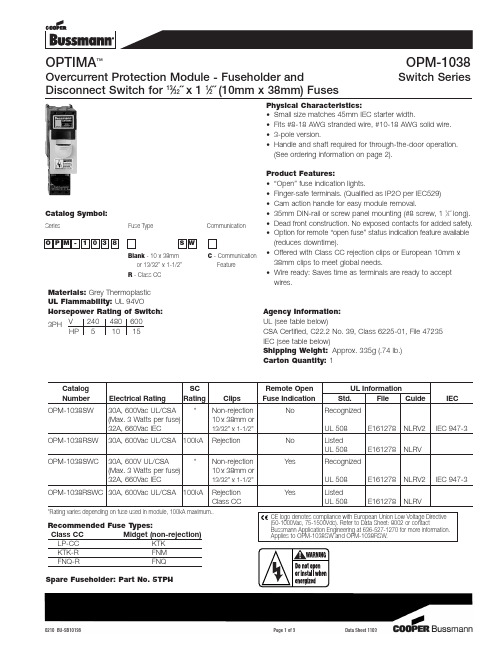
Materials: Grey Thermoplastic UL Flammability: UL 94VOHorsepower Rating of Switch:3PH V 240480600HP 51015Agency Information:UL (see table below)CSA Certified, C22.2 No. 39, Class 6225-01, File 47235IEC (see table below)Shipping Weight:Approx. 335g (.74 lb.)Carton Quantity: 1Physical Characteristics:•Small size matches 45mm IEC starter width.•Fits #8-18 AWG stranded wire, #10-18 AWG solid wire.•3-pole version.•Handle and shaft required for through-the-door operation. (See ordering information on page 2).Product Features:•“Open” fuse indication lights.•Finger-safe terminals. (Qualified as IP2O per IEC529)•Cam action handle for easy module removal.•35mm DIN-rail or screw panel mounting (#8 screw, 1 1⁄4˝ long).•Dead front construction. No exposed contacts for added safety.•Option for remote “open fuse” status indication feature available (reduces downtime).•Offered with Class CC rejection clips or European 10mm x 38mm clips to meet global needs.•Wire ready: Saves time as terminals are ready to accept wires.OPTIMA ™OPM-1038Overcurrent Protection Module - Fuseholder and Switch SeriesDisconnect Switch for 13⁄32˝ x 1 1⁄2˝ (10mm x 38mm) FusesCatalog SC Remote Open UL Information Number Electrical Rating Rating ClipsFuse IndicationStd.File Guide IECOPM-1038SW30A, 600Vac UL/CSA *Non-rejection NoRecognized (Max. 3 Watts per fuse)10x 38mm or32A, 660Vac IEC13/32” x 1-1/2”UL 508E161278NLRV2IEC 947-3OPM-1038RSW 30A, 600Vac UL/CSA 100kA Rejection No Listed UL 508E161278NLRVOPM-1038SWC30A, 600V UL/CSA*Non-rejection YesRecognized (Max. 3 Watts per fuse)10x 38mm or32A, 660Vac IEC13/32” x 1-1/2”UL 508E161278NLRV2IEC 947-3OPM-1038RSWC 30A, 600Vac UL/CSA 100kARejection YesListed Class CCUL 508E161278NLRV*Rating varies depending on fuse used in module, 100kA maximum..Recommended Fuse Types:Class CC Midget (non-rejection)LP-CC KTK KTK-R FNM FNQ-R FNQ Spare Fuseholder: Part No. 5TPHO P M -1038S WSeriesFuse TypeCommunicationC - CommunicationFeatureBlank - 10 x 38mmor 13/32” x 1-1/2”R - Class CCCatalog Symbol:Ordering Information for External Handle*:OPTIMA Module + CDRKBS12 + Handle + Shaft= Complete Disconnect Switch (without fuses)1. Order Cooper Bussmann part number CDRKBS12.2. Select the appropriate handle style (Selector or Pistol).3. Select the shaft corresponding to the handle type and mounting depth required.*All switchable OPM-1038 modules come standard with a small black handle CooperBussmann part number CDRKBS12 must be ordered for all through-the-door applications.Dimensional DataExtended Shafts - Shaft Dimension (K 6x6mm )For Handle Mounting Shaft Catalog TypeDepth **Length Number 4.2 - 5.0˝ 3.3˝ (85mm)BDS85S 5.0 - 5.8˝ 4.1˝ (105mm)BDS105S 5.6 - 6.4˝ 4.7˝ (120mm)BDS120S Selector6.0 - 6.7˝ 5.1˝ (130mm)BDS130S7.1 -8.7˝7.1˝ (180mm)BDS180S 10.7 - 11.5˝9.8˝ (250mm)BDS250S 13.8 - 14.6˝13.0˝ (330mm)BDS330S 6.2 - 6.7˝ 5.9˝ (150mm)BDS1507.0 - 7.5˝ 6.7˝ (170mm)BDS170Pistol10.7 - 11.3˝10.4˝ (265mm)BDS26516.0 - 16.6˝15.8˝ (400mm)BDS40020.0 - 20.5˝19.7˝ (500mm)BDS500**Mounting depth is the distance from the outside of the door to the disconnect switch. Shaft can be cut to desired length.0.57∑ (± 0.03)Selector Handles - for use with shafts K 0.24˝ x 0.24˝ (K 6x6mm)NEMA IEC Color Defeatable Padlockable Weight Catalog type type(lbs)number All marked both O/l & Off/On 1IP54Black ——0.09CBDH1S 1IP54Red/Yel ——0.09CBDH2S 1IP54Black —Yes 0.12CBDH15S 1IP54Red/Yel —Yes 0.12CBDH16S 1,3R,12IP65Black —Yes 0.16CBDH3S 1,3R,12IP65Red/Yel —Yes 0.16CBDH4S 1,3R,12IP65Black Yes Yes 0.16CBDH5S 1,3R,12IP65Red/YelYesYes0.16CBDH6SPistol Handles - for use with shafts K 0.24˝ x 0.24˝ (K 6x6mm)NEMA IEC Color Marking Length Defeatable Padlockable Weight Catalog type type inches/mm (lbs)number All marked both O/l & Off/On1,3R,12IP65 Black O/l & Off/On 1.8/45 Yes Yes 0.28BDH561,3R,12IP65 Red/Yel O/l & Off/On 1.8/45 Yes Yes 0.28 BDH571,3R,12 IP65 Black O/l & Off/On 2.6/65 Yes Yes 0.29 BDH581,3R,12 IP65 Red/Yel O/l & Off/On 2.6/65 Yes Yes 0.29BDH591,3R,12,4,4X IP66 Black O/l & Off/On 2.6/65 Yes Yes 0.29 CDHXB65L61,3R,12,4,4X IP66 Red/Yel O/l & Off/On2.6/65 Yes Yes 0.29 CDHXY65L6Status Output Specifications:*Minimum operating voltage: 460Vac, 3-phase *Maximum operating voltage: 620Vac, 3-phaseStatus output maximum conducting current: 40mA Status output maximum on resistance: 35 ohms @ 40mAStatus output typical off resistance: >10 Mohm Status output maximum turn-on and turn-off delay: 850 milli-secondStatus Output Interface Specifications:Rated Voltage: Recommended 5-35Vdc, 300Vac max.Rated Current: 40mA max.Wire Size: #28-14 AWG Torque: 2.25 lb. in.Open Fuse Indicator Status Output Description:The open fuse indicator status output acts very much like an on/off switch. With all three fuses in place and operating properly, this status output has a high resistance value of greater than ten mega-ohms. When one or more of the fuses are open, the status output becomes turned-on with a resistance value less than 35 ohms. This status output withstands voltage (ac or dc) up to 35V at off-state and conducts current up to 40 milli-amps at on-state.Applying voltage and current exceeding these limits will result in damage to the components inside this statusoutput device permanently. There is some time-delay when the status output changes on/off state. The open fuse communications or status output device includes optical isolators within the unit.Communications output states:Fuse Good NO - High Resistance, >10 megohms Opened Fuse NC - Low Resistance, < 35 ohmsOPEN FUSE INDICATIONNote: Operating this device beyond the above limits willcause permanent damage to the components on the board.For applications requiring status output below a system voltage of 460V, contact Bussmann.The examples shown below illustrate typical interface toProgrammable Logic Controllers.STATUS OUTPUTTTL Digital InputPC / PLCVcc (5V to 35V)Pull up Resistor (> 1K)EXAMPLE 1: DIRECT INTERFACE TO PC/PLCPC / PLC EXAMPLE 2: INTERFACE TO PC / PLC WITH OPTICAL ISOLATIONCurrent-Limiting ResistorOptical IsolatorTTL Digital InputVcc (5V to 35V)ISOLATED AC OR DC POWER SOURCESTATUS OUTPUTPull up Resistor (> 1K)Note: When energized (switch in the “on” position), a low load terminal voltage willbe present when fuses are open or when pullout module is removed. The leakage current is limited to .5mA maximum .Example of Output Voltage with three open fuses or pullout module removed.Catalog Number OPM-1038RSW, OPM-1038SW OPM-1038-RSWC, OPM-1038SWC Types of Indication Standard Communication System Voltage Load Terminal Voltage (1L1-3L2-5L3)(2T1-4T2-6T3)125Vdc *12Vdc *31Vdc *480Vac, 3-phase 26Vac 56Vac 600Vac, 3-phase 33Vac 88VacThere is no voltage at the load terminals (2T1-4T2-6T3) on the switch version (SW suffix) when the switch is in the “off” position.*The communication device requires a minimum circuit voltage (1L1-3L2-5L3) of 460V for the status indicating device to operate. Below 460V , but above 120V , the indicator lights will luminate, but there will not be any communication status output.The only controlled copy of this Data Sheet is the electronic read-only version located on the Cooper Bussmann Network Drive. All other copies of this document are by definition uncontrolled. This bulletin is intended to clearly present comprehensive product data and provide technical informa-tion that will help the end user with design applications. Cooper Bussmann reserves the right, without notice, to change design or construction of any products and to discontinue or limit distribution of any products. Cooper Bussmann also reserves the right to change or update, without notice, any technical information contained in this bulletin. Once a product has been selected, it should be tested by the user in all possible applications.。
杭州之江开关股份有限公司HSJR1系列热过载继电器使用说明书

HSJR1系列热过载继电器使用说明书杭州之江开关股份有限公司1、用途和适用范围HSJR1系列热过载继电器(以下简称热继电器)适用于交流 50Hz,额定电压690V及以下,额定电流0.1-400A的低压配电系统中,作为三相交流电动机的过载、断相保护之用。
产品符合GB/T14048.4标准。
2、正常工作条件和安装条件1)、安装地点的海拔不超过2000m。
2)、周围介质温度:上限为+40℃,下限为-5℃。
3)、安装地点的相对湿度在温度为+40℃时,空气的相对湿度不超过50%,在较低的温度下可以允许有较高的相对湿度,例如20℃时达90%对由于温度变化偶尔产生的凝露应采取特殊的措施。
4)、污染等级:3级5)、安装类别:Ⅲ6)、安装条件: 垂直安装,与安装面前后倾斜度不超过±5°。
7)、安装方式:HSJR1-25-93可插接安装也可独立安装;HSJR1-150为插接安装; HSJR1-F200、HSJR1-F400为独立安装;3、型号及含义整定电流范围,用最大值表示壳架等级额定电流F:表示复式独立安装设计序号热过载继电器企业代号(杭申)4、功能结构热继电器除了具有过载保护和断相保护功能外,还具有下述结构特点:a)具有周围空气温度补偿;b)具有动作灵活性检测机构;c)具有手动复位或自动复位功能;d)具有检测按钮,能手动断开常闭触头;e)具有整定电流连续可调装置。
5、主要规格和技术数据参数5.1、热继电器符合“1”型协调配合类型,选用的SCPD为RT16-00(NT00),整定电流、Iq值、电动机功率及配套的交流接触器见表1表1电流和约定发热电流见表2 表25.3 热继电器的脱扣级别为10A级,其时间-电流特性曲线见图1,动作特征见表3表3动作特征序号各项负载不平衡时各项负载平衡时温度补偿性能1212341234整定电流倍数任意两相另一相动作时间起始条件周围空气温度(℃)1.00.91.1501.051.201.507.201.001.201.051.30﹥2h﹤2h﹥2h﹤2h2s﹤T p≦10s﹤2h﹥2h﹥2h﹤2h﹤2min冷 态按序1试验后冷 态20±520±540±5-5±2按序1试验后按序1试验后按序1试验后冷 态冷 态冷 态按序3试验后6、结构及原理热继电器是由发热元件、双金属片、触点及一套传动和调整机构组成。
三相环型电机风冷保护器说明说明书

Page 137HM | MOTOR PROTECTORSHERMETICALLY SEALED ON-WINDING, 3-PHASE SPECIFICATIONSFeatures and BenefitsIntroduction• Protect WYE (Star) wound 3-phase motors from 1 to 6-7HP. Used in refrigeration compressors, submeersible pumps and other restrictive environments.• In-line protection in a small, rugged, welded construction. Low profile shape allows for close coupling to motor windings.• Klixon® snap-action discs assure positive make and break action and controlled temperature differential.• Designed for low and high side pressure applications.This protector is designed to protect 3-phase refrigeration and air conditioning compressor motors from excessive winding temperature; however, applications may be made to any WYE wound 3-phase motors where environmental conditions require a hermetic seal. The low profile permits the device to be installed directly on motor windings for closely coupled temperature monitoring, thus enhancing over-temperature protection against loss of refrigeration charge, low voltage locked rotor, and single-phasing (loss of phase). The 37HM is designed to reduce installation costs by replacing pilot control systems with a simple, economical, compact device.The basic element of the 35HM is the famous Klixon® Snap Acting Disc.Maximum Recommended Locked Rotor CurrentCurrent ratings are based on life test data which has demonstrated high reliability at 0.7 power factor on Sensata test boards. These capacities are intended as a guide for application work.Standard Operating TemperaturesPage 2DIAGRAMS37HM Hermetic Motor ProtectorElectrical SchematicUnit Ins mmW 0.7820H 0.512.7P10.717.8L 1.2632P20.092.3P30.256.4Protector ShellC o m p r e s s o r M o t o r W i n d i n g sThird connection for WYE-centerpoint is made to housingby welded lead, QC tab or other customer optionAGENCY APPROVALS & CERTIFICATIONS37HM CODE SYSTEMQuick ConnectsWire LeadsSleeves, etc.(XXX)(XXX)When making an inquiry on Klixon® hermetically sealed motor protectors, be certain to specify the entire part number for your application,if known. The six digits following the series identification indicate your specific electrical and physical requirement.Page 3Rev:09/28/CONTACT USSensata Technologies, Inc. (“Sensata”) data sheets are solely intended to assist designers (“Buyers”) who are developing systems thatincorporate Sensata products (also referred to herein as “components”). Buyer understands and agrees that Buyer remains responsiblefor using its independent analysis, evaluation and judgment in designing Buyer’s systems and products. Sensata data sheets havebeen created using standard laboratory conditions and engineering practices. Sensata has not conducted any testing other than thatspecifically described in the published documentation for a particular data sheet. Sensata may make corrections, enhancements,improvements and other changes to its data sheets or components without notice.Buyers are authorized to use Sensata data sheets with the Sensata component(s) identified in each particular data sheet. HOWEVER, NOOTHER LICENSE, EXPRESS OR IMPLIED, BY ESTOPPEL OR OTHERWISE TO ANY OTHER SENSATA INTELLECTUAL PROPERTY RIGHT, ANDNO LICENSE TO ANY THIRD PARTY TECHNOLOGY OR INTELLECTUAL PROPERTY RIGHT, IS GRANTED HEREIN. SENSATA DATA SHEETSARE PROVIDED “AS IS”. SENSATA MAKES NO WARRANTIES OR REPRESENTATIONS WITH REGARD TO THE DATA SHEETS OR USEOF THE DATA SHEETS, EXPRESS, IMPLIED OR STATUTORY, INCLUDING ACCURACY OR COMPLETENESS. SENSATA DISCLAIMSANY WARRANTY OF TITLE AND ANY IMPLIED WARRANTIES OF MERCHANTABILITY, FITNESS FOR A PARTICULAR PURPOSE, QUIETENJOYMENT, QUIET POSSESSION, AND NON-INFRINGEMENT OF ANY THIRD PARTY INTELLECTUAL PROPERTY RIGHTS WITH REGARDTO SENSATA DATA SHEETS OR USE THEREOF.All products are sold subject to Sensata’s terms and conditions of sale supplied at SENSATA ASSUMES NO LIABILITYFOR APPLICATIONS ASSISTANCE OR THE DESIGN OF BUYERS’ PRODUCTS. BUYER ACKNOWLEDGES AND AGREES THAT IT IS SOLELYRESPONSIBLE FOR COMPLIANCE WITH ALL LEGAL, REGULATORY AND SAFETY-RELATED REQUIREMENTS CONCERNING ITS PRODUCTS,AND ANY USE OF SENSATA COMPONENTS IN ITS APPLICATIONS, NOTWITHSTANDING ANY APPLICATIONS-RELATED INFORMATIONOR SUPPORT THAT MAY BE PROVIDED BY SENSATA.Mailing Address: Sensata Technologies, Inc., 529 Pleasant Street, Attleboro, MA 02703, USA.Americas+1 (508) 236-2551electrical-protection-sales@sensata.comEurope, Middle East & Africa+3 174 357 8156*********************.comAsia Pacific***************************.comChina +86 (21)2306 1651India +91 (40)4033 9611Japan +81 (45)277 7104Korea +82 (53) 644 9685Rest of Asia +65(6478)6860。
SIEMENS 3UA50,3UA52 断相保护热过载继电器 说明书
断相保护热过载继电器 3UA50,3UA52GB14048.4,DIN VDE0660 第102部分,IEC 60947-4-1Q/SMS 001,XK06-201 0023使用说明书编号: 4NEB 601 1482-30 *5中 文A001253!防护等级按IEC 60529为IP20级。
触指安全性符合GB4942.2和DIN VDE0106 第100部分。
调试维修应由专业人员按本使用说明书进行。
图I 3UA50:与3TD40/41,3TE40,3TF30/31/40/41,3TW10/12/40/41,3TB40/41接触器组合安装。
配用附件3UX1418也可单独安装。
3UA52:与3TD42/43,3TE42,3TF32/33/42/43,3TW13/42/43,3TB42/43接触器组合安装。
配用附件3UX1420也可单独安装。
安装安装尺寸见图II (单位:mm)a 3UA50:配用附件3UX1418单独安装。
3UA52:配用附件3UX1420单独安装。
b 3UA50:与3TF30/31接触器组合安装。
c 3UA50:与3TF40/41接触器组合安装。
(I :带有1NO 或1NC 辅助触点的接触器。
II :带有1NO+1NC 或2NO+2NC 辅助触点的接触器。
) d 3UA52:与3TF32/33接触器组合安装。
e 3UA52:与3TF42/43接触器组合安装。
注:1)至接地部件的最小距离。
2)卡装在 标准安装轨(按DIN EN50 022)上。
3)到方形试验按钮(行程3mm )的距离。
到圆形复位按钮(行程2.5mm )的距离要小2.5mm 。
4)辅助触头组。
允许安装位置见图 IIIa 热过载继电器与接触器组合安装。
b 热过载继电器单独安装。
应避免剧烈的冲击或长时间的振动。
安装:卡装在35mm 标准安装轨(DIN EN50 022)上。
或用2枚螺钉以及平垫圈和弹簧垫圈紧固在平面上。
三相电缆互锁 для Magnum 固定电路保护器(类型32互锁)说明书
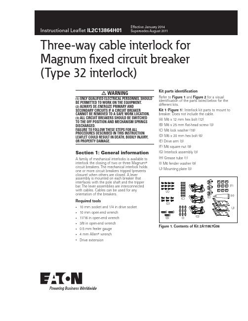
Three-way cable interlock for Magnum fixed circuit breaker (Type 32 interlock)warning(1) Only qualified electrical persOnnel shOuld be permitted tO wOrk On the equipment. (2) always de-energize primary and secOndary circuits if a circuit breaker cannOt be remOved tO a safe wOrk lOcatiOn.(3) all circuit breakers shOuld be switched tO the Off pOsitiOn and mechanism springs discharged.failure tO fOllOw these steps fOr all prOcedures described in this instructiOn leaflet cOuld result in death, bOdily injury, Or prOperty damage.Section 1: General information A family of mechanical interlocks is available to interlock the closing of two or three Magnum T circuit breakers. The mechanical interlock holds one or more circuit breakers tripped (prevents closure) when others are closed. A lever assembly is mounted on each breaker that interfaces with the pole shaft and the tripper bar. The lever assemblies are interconnected with cables. Cables can be used for any orientation of the breakers.Required tools• 10 mm socket and 1/4 in drive socket• 10 mm open-end wrench• 11/16 in open-end wrench• 3/8 in open-end wrench• 0.5 mm feeler gauge• 4 mm Allen T wrench• Drive extension Kit parts identificationRefer to Figure 1 and Figure 2 for a visual identification of the parts listed below for the different kits.Kit 1 (Figure 1): Interlock kit parts to mount to breaker. Does not include the cable.(A) M6 x 12 mm hex bolt (12)(B) M6 x 25 mm flat-head screw (3)(C) M6 lock washer (18)(D) M6 x 20 mm hex bolt (6)(E) Drive arm (3)(F) M6 square nut (9)(G) Interlock assembly (3)(H) Grease tube (1)(I) M6 fender washer (9)(J) Mounting plate (3)(A)(B)(C)(D)(E)(H)(F)(G)(I)(J) Figure 1. Contents of Kit 2A11857G062Instructional Leaflet IL2C13864H01Effective January 2014Three-way cable interlock for Magnum fixed circuit breaker(Type 32 interlock)eaton Kit 2 (Figure 2): Interconnecting kit. Includes cables.(K) Cable bracket (2)(L) M6 lock washer (4)(M) M6 x 10 mm thread-forming screws (4)(N) Cable assembly (2) (in 5 ft, 6 ft, 8 ft, and 10 ft lengths)otee:N Three sets of kits (six cables) are required to connect three breakers so that any two of the three breakers can be closed at once. Closing two breakers holds the third one tripped. Refer to T able 1 on Page 4.(K)(L)(N)(M)Figure 2. Contents of Kit 2A11858G01–04Section 2: Installation of two-waycable interlockProceed with the following 11 steps:Step 1e: Remove the front cover by unscrewing the hex head captive bolts (four for three-pole, six for four-pole) that join the cover to the breaker housing using a 10 mm 1/4 in drive socket. Then hold the charge handle down approximately 45 degrees to pull off the cover.Figure 3. Step 1Step 2e: Remove the knockout from the right side of the front cover using pliers to break out the U-shaped tab. Carefully file any excess material from broken edge.Figure 4. Step 2Step 3e: Install the drive arm (E) to the right end of the pole shaft with the drive arm lever extending downward as shown. Use an M6 x 25 mm flat-head screw (B) to make the connection and torque to 65 in-lb to 85 in-lb (7.3 Nm to 9.6 Nm).Figure 5. Step 33Instructional Leaflet IL2C13864H01Effective January 2014Three-way cable interlock for Magnum fixed circuit breaker (Type 32 interlock)eaton Step 4e: Reinstall front cover removed in Step 1.Step 5e: Attach the interlock assemblies (G) and cable brackets (K) to the mounting plates (J). The interlock assembly is attached to the mounting plate using three M6 x 12 hex bolts (A) and lock washers (C). Torque to 40 in-lb to 50 in-lb (4.5 Nm to 5.6 Nm). Fasten the cable brackets to the mounting plates using two M6 x 10 thread-forming screws (M) and lock washers (L). Torque to 65 in-lb to 85 in-lb (7 Nm to 9 Nm).Figure 6. Step 5Step 6e: Attach the interlock assemblies from Step 5 to the right side of the breakers. Start by removing the M6 hex bolt, nut, lock washer, and grounding (earthing) wire installed in the lower front corner of the mounting foot. This bolt assembly will be reinstalled through the adapter plate near the end of this step.Slide an M6 square nut (F) into the slot in the upper rear part of the case with the flat face toward the outside. The nut may have to be tapped to fully seat it into the slot. Install an M6 x 20 hex bolt (D), lock washer (C), and flat spacer washer (I) into the square nut a few turns. Locate another captive square nut into a slot in the upper part of the case, forward of the square nut just installed. Install another M6 x 20 hex bolt, lock washer, and spacer washer combination in this square nut. Slide the spacer washers fully against the case and the lock washers fully against the heads of the bolts. This creates a space into which the open slots in the top of the mounting plate will slide.Now insert the mounting bracket slots onto the upper bolts and rotate the bracket down against the side of the breaker. Make sure that the drive paddle slides in behind the wireform tripper bar, and the follower arm slides in behind the drive arm pin.Reinstall the lower front bolt assembly (removed earlier), making sure to reconnect the ground (earth) wire. Tighten the upper bolts to stabilize the plate. Now insert an M6 x 12 hex bolt and M6 lock washer through the rear plate and mounting foot, retaining it with square nut on the inside of the mounting foot. Torque to 65 in-lb to 85 in-lb (7 Nm to 9 Nm).Check the interference of the lever assembly to the breaker toensure that flapper arm is behind tripper bar, and follower is BEHIND drive arm pin. If not, remove adapter plate and reinstall properly. Check clearances between end of drive arm and end of follower (1 mm to 4 mm). The tip of the pin on the end of the drive arm should protrude slightly beyond the follower. If this condition is not observed, it may be necessary to adjust the position of the mounting bracket relative to the breaker using upper spacer washers.Figure 7. Step 6Step 7e: At this point in the process, check the functioning of the lever assemblies of each breaker by performing the three following checks in conjunction with provided graphics:Check 1e: With the breaker OPEN and CONNECTED, observe the position of the lower drive lever on each breaker. The gap between the lower right-hand corner of the drive lever and the mountingbracket flange should be from 0 mm to 2 mm (see Figure 8 Breaker OPEN). Now CLOSE the breaker. The drive lever should rotate 60 degrees counterclockwise. There should be a minimum gap of 1 mm and a maximum gap of 4 mm between the lower left-hand corner of the lever and the mounting bracket flange (see Figure 8 Breaker CLOSED). If either of these gaps are out of specification, the installation should not continue . Consult Eaton for additionalinstructions.Figure 8. Step 74Instructional Leaflet IL2C13864H01Effective January 2014Three-way cable interlock for Magnum fixed circuit breaker(Type 32 interlock)eaton Step 8e: This step describes how to route the cables. Beforeinstalling the cables, however, check to be sure that all cables move freely in their cable housing. Route the cables between cassettes in such a fashion that there are no sharp bends in the cable housing and the total number of bends are minimized. The minimum allowable cable housing bend radius is 4 in (102 mm). Aftercompleting the installation and adjustment of the cables, attach the cable housing to the structure at a suitable number of points along the cable run, being careful not to compress the cable housing. The use of plastic wire clamps or wire ties will minimize the likelihood of binding the cables. After the cables are installed, recheck to be sure that the cables still move freely. Refer to T able 1 and Figure 9 for installation details.T able 1. Step 8 Cable Routingtype 32 (six cables)from cassette/fitting to breaker/fitting 1A 1C 3D 2B 2A 2C 1D 3B 3A 3C2D 1BFigure 9. Step 85Instructional Leaflet IL2C13864H01Effective January 2014Three-way cable interlock for Magnum fixed circuit breaker (Type 32 interlock)eaton Step 9e: This step describes how to attach the cables to the interlock assembly and illustrates the attachment of the driven (long rod) end of the cable. Remove nut and spacer tube from the end of the rod. Slide the rubber boot toward the tip of the rod. Unthread the outer bulkhead nut and slide the nut and lock washer toward the tip. Insert the threaded end of the rod into the swivel fitting whilesimultaneously sliding the smaller diameter portion of the bulkhead fitting into the slot in the mounting plate. Raise the cable assembly until the threaded portion of the bulkhead fitting enters the slotted hole and fasten the bulkhead washer and nut finger tight. Adjust the two bulkhead nuts so that the fitting is approximately centered on the cable mounting bracket and hand tighten the nuts. Slide the rubber boot back into place over the end of the bulkhead fitting. Replace the tube spacer and upper nut on the rod end. The lower nuts should be shouldered against the end of the thread and the upper nuts tightened against the spacer tube. While holding the lower nuts, torque to 30 in-lb to 40 in-lb (3.3 Nm to 4.5 Nm). Repeat this process to attach the other end of the cables to the other breaker interlock assembly. See Figure 9 for number and mounting position of cables.The only difference is that the drive (short) rod uses a compression spring. Locate compression spring for Position A below the swivel fitting. The compression spring for the Position C must be located above the swivel fitting (see Figure 10). Therefore, the spring for Position C must be removed before installation and replaced as shown before the installation of the upper rod nut.otee:N Hold the cable rod with pliers while removing and installing the nuts to prevent the cable from rotating.Figure 10. Step 96Instructional Leaflet IL2C13864H01Effective January 2014Three-way cable interlock for Magnum fixed circuit breaker(Type 32 interlock)eaton Step 10 This step describes how to adjust the cables(see Figure 10 and Figure 11 for details). The initial adjustments are made with all breakers OPEN. The bulkhead nuts for each cable should be set so that they are approximately midway on the threaded bulkhead fitting (see Figure 10). The bulkheadnuts should not be moved anymore. Check if all endplates are in the horizontal position and if there is a 1 mm gap as shown in Figure 11 A . To adjust the endplates correctly, use the upper cable nuts above the spacer tube. Check the function of the mechanical interlock assembly according to the logic table (T able 2) onPage 7. Further adjustments (if necessary) can be done by using the bulkhead nuts. Adjust the upper cable nuts again so that all endplates are in the horizontal position. Check the function of the mechanical interlock assembly again according to the logic table (T able 2) on Page 7. Keep adjusting the interlock assembly until it functions correctly. Once the adjustment is completed, the bulkhead nuts and the upper cable nuts can be secured to ensure safety by applying sealing wax.Figure 11. Step 107Instructional Leaflet IL2C13864H01Effective January 2014Three-way cable interlock for Magnum fixed circuit breaker (Type 32 interlock)eaton Step 11e: Test of a six-cable interlock assembly (Type 32):1. Open all breakers.2. Charge and close Breaker A . Breakers B and C should be held in the OPEN condition. Open Breaker A .3. Charge and close Breaker B . Breakers A and C should be held in the OPEN condition. Open Breaker B .4. Charge and close Breaker C . Breakers A and B should be held in the OPEN condition. Open Breaker C .5. Charge and close Breakers A and B . Breaker C should be held in the OPEN condition. Open Breakers A and B .6. Charge and close Breakers B and C . Breaker A should be held in the OPEN condition. Open Breakers B and C .7. Charge and close Breakers A and C . Breaker B should be held in the OPEN condition. Open Breakers A and C .T able 2. Step 11 Logictype 32—six-cable interlock assemblyaBC000100010001110011101Eaton1000 Eaton Boulevard Cleveland, OH 44122 United States © 2014 EatonAll Rights ReservedPrinted in USAPublication No. IL2C13864H01 / Z14770 January 2014Eaton is a registered trademark.All other trademarks are propertyof their respective owners.Three-way cable interlock for Magnum fixed circuit breaker(Type 32 interlock)Instructional Leaflet IL2C13864H01Effective January 2014DISCLaIMeR oF WaRRantIeS anD LIMItatIon oF LIaBILItYThe information, recommendations, descriptions, and safety notations in this document are based on Eaton experience and judgment and may not cover all contingencies. If further information is required, consult an Eaton sales office.Sale of the product shown in this literature is subject to the terms and conditions outlined in appropriate Eaton selling policies or other contractual agreements between Eaton and the purchaser. THERE ARE NO UNDERSTANDINGS, AGREEMENTS, OR WARRANTIES, EXPRESSED OR IMPLIED, INCLUDING WARRANTIES OF FITNESS FOR A PARTICULAR PURPOSE OR MERCHANTABILITY, OTHER THAN THOSE SPECIFICALL Y SET OUT IN ANY EXISTING CONTRACT BETWEEN THE PARTIES. ANY SUCH CONTRACT STATES THE ENTIRE OBLIGATION OF EATON. THE CONTENTS OF THIS DOCUMENT SHALL NOT BECOME PART OF OR MODIFY ANY CONTRACT BETWEEN THE PARTIES.In no event will Eaton be responsible to the purchaser or user in contract, in tort (including negligence), strict liability, or otherwise for any special, indirect, incidental, or consequential damage or loss whatsoever, including but not limited to damage or loss of use of equipment, plant or power system, cost of capital, loss of power, additional expenses in the use of existing power facilities, or claims against the purchaser or user by its customers resulting from the use of the information, recommendations, and descriptions contained herein.The information contained in this manual is subject to change without notice.。
三相交流电动机保护器AMDTH-X E01□系列使用说明书
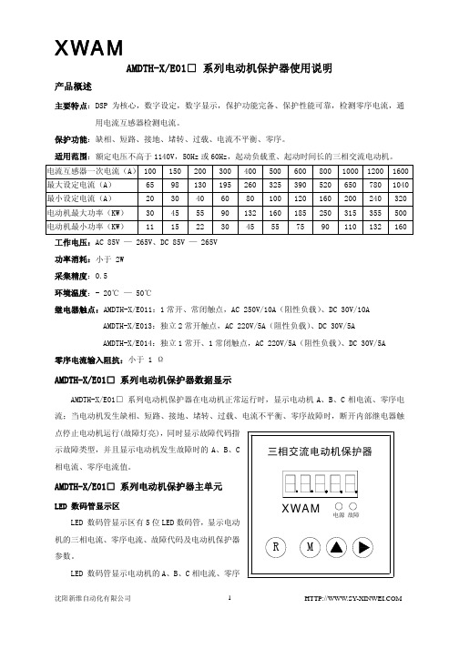
AMDTH-X/E01□ 系列电动机保护器使用说明产品概述主要特点:DSP 为核心,数字设定,数字显示,保护功能完备、保护性能可靠,检测零序电流,通用电流互感器检测电流。
保护功能:缺相、短路、接地、堵转、过载、电流不平衡、零序。
适用范围:额定电压不高于1140V,50Hz或60Hz,起动负载重、起动时间长的三相交流电动机。
电流互感器一次电流(A)100 150 200300400500600800 1000 12001600最大设定电流(A) 65 98 130195260325390520 650 7801040最小设定电流(A) 20 30 40 60 80 100120160 200 240320电动机最大功率(KW) 30 45 55 90 132160185250 315 355500电动机最小功率(KW) 11 15 22 30 45 55 75 90 110 132160工作电压:AC 85V — 265V、DC 85V — 265V功率消耗:小于 2W采集精度:0.5环境温度:- 20℃ — 50℃继电器触点:AMDTH-X/E011:1常开、常闭触点,AC 250V/10A(阻性负载)、DC 30V/10AAMDTH-X/E013:独立2常开触点,AC 220V/5A(阻性负载)、DC 30V/5AAMDTH-X/E014:独立1常开、1常闭触点,AC 220V/5A(阻性负载)、DC 30V/5A零序电流输入阻抗:小于 1 ΩAMDTH-X/E01□系列电动机保护器数据显示AMDTH-X/E01□ 系列电动机保护器在电动机正常运行时,显示电动机A、B、C相电流、零序电流;当电动机发生缺相、短路、接地、堵转、过载、电流不平衡、零序故障时,断开内部继电器触点停止电动机运行(故障灯亮),同时显示故障代码指Array示故障类型,并且显示电动机发生故障时的A、B、C相电流、零序电流值。
三星 Sirius 3RU2116-1FB1 过载保护器用户手册说明书

● in networks with grounded star point between main and auxiliary circuit Protection class IP ● on the front ● of the terminal Shock resistance ● acc. to IEC 60068-2-27 Type of protection according to ATEX directive 2014/34/EU Certificate of suitability according to ATEX directive 2014/34/EU Reference code acc. to DIN EN 81346-2
440 V
IP20 IP20
8g / 11 ms Ex II (2) GD
DMT 98 ATEX G 001
F
2 000 m
-40 ... +70 °C -55 ... +80 °C -55 ... +80 °C -40 ... +60 °C 10 ... 95 %
3 3.5 ... 5 A
690 V 690 V 50 ... 60 Hz 5A
1.5 kW 2.2 kW 4 kW
integrated 1 for contactor disconnection 1 for message "Tripped"
0
3RU2116-1FB1 Page 2/8
04/09/2020
Subject to change without notice © Copyright Siemens
Contact rating of auxiliary contacts according to UL
西门子品牌的S0尺寸的10.40A过载保护电机保护过量电流保护器3RB3026-1VB0说明书
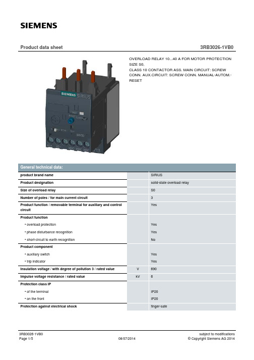
3RB3026-1VB0 Page 4/5
08/07/2014
subject to modifications © Copyright Siemens AG 2014
• finely stranded • with conductor end processing
• for AWG conductors / for auxiliary contacts
UL/CSA ratings:
No AC/DC
1 1 0 fuse gL/gG: 6 A
CLASS 10
A
10 … 40
Installation altitude / at a height over sea level / maximum Resistance against vibration Ambient temperature
• during transport • during storage • during operating Relative humidity • during operating phase EMC immunity to interference / according to IEC 60947-1 EMC emitted interference / according to IEC 60947-1 Electrostatic discharge / according to IEC 61000-4-2 Field-bound parasitic coupling / according to IEC 61000-4-3 Conductor-bound parasitic coupling BURST / according to IEC 61000-4-4 Conductor-bound parasitic coupling conductor-earth SURGE Conductor-bound parasitic coupling conductor-conductor SURGE Type of protection
三相电机过载保护器和手动重置器类目录说明书

Large Amp CEP7 Solid State Overload Relays, Automatic or Manual Adjustable Trip Class ➊➋➌➍
Directly Mounts to Contactor… ➋
Adj. Range
(A)
Overload Relay Code (◆)
0.1...0.5 D1AB CEP7-ED1AB
Standard
CA7-9...CA7-23
0.2...1.0 1.0...5.0
D1BB D1CB
CEP7-ED1BB CEP7-ED1CB
Standard Standard
3.2...16 D1DB CEP7-ED1DB
Standard
5.4...27 D1EB CEP7-ED1EB
Starter Modification Codes
Special Notes: Wye-Delta Starters - First multiply motor full load current by 58%. Then, using this figure, select appropriate Overload Relay Code from tables above.
Variable Frequency Drives - CEP7 solid state overload relays cannot be utilized on VFDs or Softstarters with Braking option.
CB7 Contactor with CEP7 Overload Relay
21
3.2...16 EDD CEP7-EEDD
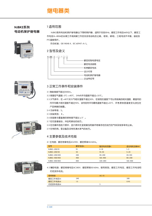
NJBK2系列电动机保护继电器 说明书
65max
+A +B +C +D +E +F +G +H +I +J +5 +10 +20
88±0.26 95max 35
65±0.5
7 订货须知
7.1 保护器名称及型号规格。根据使用要求选择控制电源电压(AC220V、AC380V),整定电流范围(2A~10A、 10A~50A、40A~200A、160A~400A、320A~800A),附件(NJBK2-200导电排、NJBK2接线座、NJBK2卡箍)。
月平均最大相对湿度不超过90%,该月的月平均最低温度不超过+25℃,并考 虑到因温度变化发生在 产品表面的凝露。 3.4 污染等级:3。 3.5 安装类别:Ⅲ。 3.6 安装面与垂直面的倾斜度不超过±5°。 3.7 在无显著摇动、冲击和振动的地方。 3.8 在无爆炸危险介质中,且介质中无呈现腐蚀和破坏绝缘存在的地方的气体及较多导电尘埃。 3.9 在有防雨、雪设备及没有充满水蒸气的地方。
NJBK2电流时间特性曲线
C
C-042
继电器类
5.2.4 接地保护动作特性。
序号 1 2
零序电流 A 0.5 1
动作时间 s ≤1 ≤1
5.2.5 电机预埋PTC热敏电阻保护动作特性: PTC热敏电阻保护是通过检测预埋在电机定子绕组或轴承上的PTC检测 器 送 出 的 热 敏 阻 值 作 为 保护 条件来判断电动机是否过热,当PTC到达动作阻值时,动作延时<1s。
2h内动作
<2min <4min <8min <12min 2s<tp≤10s 4s<tp≤10s 6s<tp≤20s 9s<tp≤30s
起始条件 冷态开始
Eaton Moeller ZB系列过载保护器说明说明书
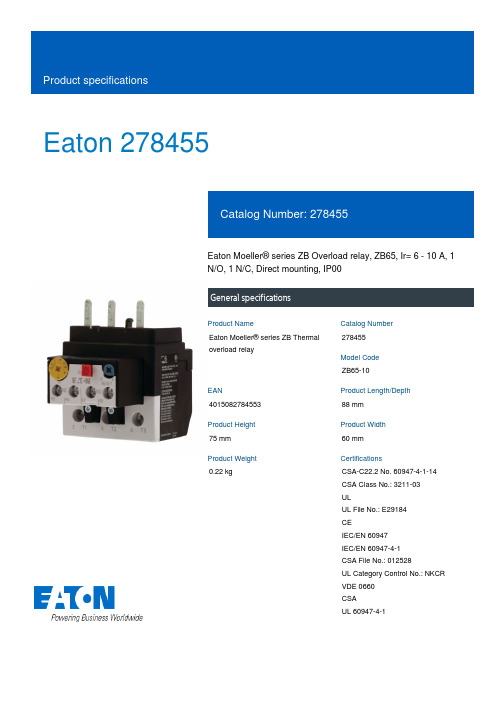
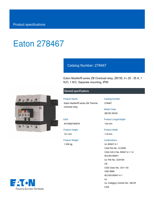
Eaton 278455Eaton Moeller® series ZB Overload relay, ZB65, Ir= 6 - 10 A, 1 N/O, 1 N/C, Direct mounting, IP00General specificationsEaton Moeller® series ZB Thermal overload relay278455ZB65-10401508278455388 mm 75 mm 60 mm 0.22 kgCSA-C22.2 No. 60947-4-1-14 CSA Class No.: 3211-03 ULUL File No.: E29184 CEIEC/EN 60947 IEC/EN 60947-4-1 CSA File No.: 012528UL Category Control No.: NKCR VDE 0660 CSA UL 60947-4-1Product NameCatalog Number Model Code EANProduct Length/Depth Product Height Product Width Product Weight Certifications10 A1 x (0.75 - 2.5) mm², Control circuit cables2 x (1 - 25) mm², Main cables2 x (0.75 - 2.5) mm², Control circuit cables1 × (1 - 25) mm², Main cablesIs the panel builder's responsibility. The specifications for the switchgear must be observed.8 mm25 °CMeets the product standard's requirements.Is the panel builder's responsibility. The specifications for the switchgear must be observed.Direct attachmentDirect mountingDoes not apply, since the entire switchgear needs to be evaluated.11 mm65 kA, CB, SCCR (UL/CSA)15 A, max. CB, SCCR (UL/CSA)100 kA, Fuse, SCCR (UL/CSA)15 A, Class J/CC, max. Fuse, SCCR (UL/CSA)40 °CMeets the product standard's requirements.Automatic Product Range Catalog Switching and protecting motorseaton-tripping-devices-characteristic-zb-overload-relay-characteristic-curve.epseaton-tripping-zb-overload-relay-characteristic-curve-002.epsDA-DC-00004844.pdfDA-DC-00004854.pdfeaton-tripping-devices-overload-relay-zb-overload-relay-dimensions-002.epseaton-tripping-devices-overload-relay-zb-overload-relay-dimensions-005.epseaton-tripping-devices-overload-relay-zb-overload-relay-3d-drawing-003.epsETN.ZB65-10IL03407008Zeaton-motor-protective-relay-zb65-zb150-overload-monitoring-exe-manual-mn03407005z-de-de-en-us.pdfzb65.stpzb65eaton-tripping-devices-overload-relay-zb-overload-relay-wiring-diagram.epsRated operational current for specified heat dissipation (In) Terminal capacity (flexible with ferrule)10.11 Short-circuit ratingStripping length (control circuit cable)Ambient operating temperature (enclosed) - min10.4 Clearances and creepage distances10.12 Electromagnetic compatibilityMounting method10.2.5 LiftingStripping length (main cable)Short-circuit current rating (high fault at 480 V)Ambient operating temperature (enclosed) - max10.2.3.1 Verification of thermal stability of enclosures Reset function CatalogsCharacteristic curve Declarations of conformity DrawingseCAD modelInstallation instructions Manuals and user guides mCAD modelWiring diagramsPush-buttonShort-circuit current rating (basic rating)5 kA, SCCR (UL/CSA)40 A, max. CB, SCCR (UL/CSA)40 A, max. Fuse, SCCR (UL/CSA)Short-circuit current rating (high fault at 600 V)15 A, Class J/CC, max. Fuse, SCCR (UL/CSA)100 kA, Fuse, SCCR (UL/CSA)10.8 Connections for external conductorsIs the panel builder's responsibility.Screw sizeM3.5, Terminal screw, Control circuit cablesM6, Terminal screw, Main cablesAdjustable current range - min6 AProtectionFinger and back-of-hand proof, Protection against direct contact when actuated from front (EN 50274)Terminal capacity (stranded)1 x (16 - 25) mm², Main cablesAmbient operating temperature - max55 °CClimatic proofingDamp heat, cyclic, to IEC 60068-2-30Damp heat, constant, to IEC 60068-2-78FeaturesTrip-free releasePhase-failure sensitivity (according to IEC/EN 60947, VDE 0660 Part 102)Test/off buttonReset pushbutton manual/autoStatic heat dissipation, non-current-dependent Pvs0 WElectrical connection type of main circuitScrew connection10.9.3 Impulse withstand voltageIs the panel builder's responsibility.Voltage rating - max600 VACAmbient operating temperature - min-25 °C10.6 Incorporation of switching devices and componentsDoes not apply, since the entire switchgear needs to be evaluated.10.5 Protection against electric shockDoes not apply, since the entire switchgear needs to be evaluated.Safe isolation440 V, Between auxiliary contacts and main contacts, According to EN 61140240 V AC, Between auxiliary contacts, According to EN 61140 440 V AC, Between main circuits, According to EN 61140Rated operational current (Ie) at AC-15, 220 V, 230 V, 240 V1.5 AClassCLASS 10 A10.13 Mechanical functionThe device meets the requirements, provided the information in the instruction leaflet (IL) is observed.10.2.6 Mechanical impactDoes not apply, since the entire switchgear needs to be evaluated.10.9.4 Testing of enclosures made of insulating materialIs the panel builder's responsibility.Number of contacts (normally closed contacts)110.3 Degree of protection of assembliesDoes not apply, since the entire switchgear needs to be evaluated.Rated operational current (Ie) at AC-15, 380 V, 400 V, 415 V0.9 AHeat dissipation per pole, current-dependent Pvid2.5 WProduct categoryAccessoriesOverload relay ZB up to 150AOverload release current setting - min6 ARated operational current (Ie) at DC-13, 60 V0.75 AEquipment heat dissipation, current-dependent Pvid7.5 WHeat dissipation capacity Pdiss0 WSuitable forBranch circuits, (UL/CSA)Temperature compensation≤ 0.25 %/K, residual error for T > 40° ContinuousTerminal capacity (solid)1 x (0.75 - 4) mm², Control circuit cables1 x (1 - 16) mm², Main cables2 x (1 - 16) mm², Main cables2 x (0.75 - 4) mm², Control circuit cablesNumber of auxiliary contacts (normally closed contacts)110.2.3.2 Verification of resistance of insulating materials to normal heatMeets the product standard's requirements.10.2.3.3 Resist. of insul. mat. to abnormal heat/fire by internal elect. effectsMeets the product standard's requirements.Rated operational current (Ie) at DC-13, 220 V, 230 V0.2 AConventional thermal current ith of auxiliary contacts (1-pole, open)6 AOverload release current setting - max10 ATerminal capacity (solid/stranded AWG)14 - 2, Main cables2 x (18 - 14), Control circuit cables10.9.2 Power-frequency electric strengthIs the panel builder's responsibility.Degree of protectionIP00Overvoltage categoryIIINumber of auxiliary contacts (change-over contacts)Pollution degree310.7 Internal electrical circuits and connectionsIs the panel builder's responsibility.Rated impulse withstand voltage (Uimp)6000 V AC4000 V (auxiliary and control circuits)10.10 Temperature riseThe panel builder is responsible for the temperature rise calculation. Eaton will provide heat dissipation data for the devices.Tightening torque1.2 Nm, Screw terminals, Control circuit cables3.5 Nm, Screw terminals, Main cablesAdjustable current range - max10 AFrame sizeZB65Screwdriver size1 x 6 mm, Terminal screw, Standard screwdriver2, Terminal screw, Pozidriv screwdriverRated operational current (Ie) at AC-15, 120 V1.5 A10.2.2 Corrosion resistanceMeets the product standard's requirements.10.2.4 Resistance to ultra-violet (UV) radiationMeets the product standard's requirements.10.2.7 InscriptionsMeets the product standard's requirements.Number of contacts (normally open contacts)1Short-circuit protection rating50 A gG/gL, Fuse, Type “1” coordinationMax. 6 A gG/gL, fuse, Without welding, Auxiliary and control circuitsEaton Corporation plc Eaton House30 Pembroke Road Dublin 4, Ireland © 2023 Eaton. All Rights Reserved. Eaton is a registered trademark.All other trademarks areproperty of their respectiveowners./socialmedia25 A gG/gL, Fuse, Type “2” coordination10.4 A690 V10 g, Mechanical, Sinusoidal, Shock duration 10 ms 0.9 AB300 at opposite polarity, AC operated (UL/CSA) R300, DC operated (UL/CSA)B600 at opposite polarity, AC operated (UL/CSA)Number of auxiliary contacts (normally open contacts)Rated operational current (Ie) at DC-13, 110 V Rated operational voltage (Ue) - max Shock resistanceRated operational current (Ie) at DC-13, 24 V Switching capacity (auxiliary contacts, pilot duty)。
YTC402 三相热继电器测试仪 用户操作手册说明书

尊敬的顾客感谢您使用本公司YTC402三相热继电器测试仪。
在您初次使用该仪器前,请您详细地阅读本使用说明书,将可帮助您熟练地使用本仪器。
我们的宗旨是不断地改进和完善公司的产品,因此您所使用的仪器可能与使用说明书有少许的差别。
如果有改动的话,我们会用附页方式告知,敬请谅解!您有不清楚之处,请与公司售后服务部联络,我们定会满足您的要求。
由于输入输出端子、测试柱等均有可能带电压,您在插拔测试线、电源插座时,会产生电火花,小心电击,避免触电危险,注意人身安全!1、慎重保证本公司生产的产品,在发货之日起三个月内,如产品出现缺陷,实行包换。
三年(包括三年)内如产品出现缺陷,实行免费维修。
三年以上如产品出现缺陷,实行有偿终身维修。
如有合同约定的除外。
2、安全要求请阅读下列安全注意事项,以免人身伤害,并防止本产品或与其相连接的任何其它产品受到损坏。
为了避免可能发生的危险,本产品只可在规定的范围内使用。
只有合格的技术人员才可执行维修。
—防止火灾或人身伤害使用适当的电源线。
只可使用本产品专用、并且符合本产品规格的电源线。
正确地连接和断开。
当测试导线与带电端子连接时,请勿随意连接或断开测试导线。
产品接地。
本产品除通过电源线接地导线接地外,产品外壳的接地柱必须接地。
为了防止电击,接地导体必须与地面相连。
在与本产品输入或输出终端连接前,应确保本产品已正确接地。
注意所有终端的额定值。
为了防止火灾或电击危险,请注意本产品的所有额定值和标记。
在对本产品进行连接之前,请阅读本产品使用说明书,以便进一步了解有关额定值的信息。
·请勿在无仪器盖板时操作。
如盖板或面板已卸下,请勿操作本产品。
使用适当的保险丝。
只可使用符合本产品规定类型和额定值的保险丝。
避免接触裸露电路和带电金属。
产品有电时,请勿触摸裸露的接点和部位。
YTC402三相热继电器测试仪 湖北仪天成电力设备有限公司在有可疑的故障时,请勿操作。
如怀疑本产品有损坏,请本公司维修人员进行检查,切勿继续操作。
PMC-550J 说明书 (V1.2)

PMC-550J低压电动机保护控制器用户手册(V1.2)深圳市中电电力技术有限公司本说明书版权属深圳市中电电力技术有限公司所有,未经书面许可,不得复制,传播或使用本文件及其内容,违犯者将要对损坏负责。
深圳市中电电力技术有限公司保留所有版权。
我们已经检查了本手册关于描述硬件和软件保持一致的内容,由于不可能完全消除差错,本手册中的数据将定期审核,欢迎提出修改建议,以后版本如有变动,恕不另行通知。
目录1 装置简介 (1)1.1 概述 (1)1.2 产品特点 (1)2 技术指标 (2)2.1 环境条件 (2)2.2 额定参数 (2)2.3 测量精度 (3)2.4 保护定值误差 (3)2.5 电气绝缘性能 (4)2.6 机械性能 (4)2.7 电磁兼容性能 (4)3 功能说明 (5)3.1 保护功能 (7)3.1.1 短路保护 (7)3.1.2 接触器分断能力保护 (7)3.1.3 阻塞保护 (8)3.1.4 过负荷保护 (8)3.1.5 过载保护(反时限) (8)3.1.6 接地保护 (9)3.1.7 电流不平衡保护 (9)3.1.8 欠载保护 (9)3.1.9 欠功率保护 (9)3.1.10 断相保护 (9)3.1.11 欠压保护 (9)3.1.12 过压保护 (10)3.1.13 tE时间保护 (10)3.1.14 起动超时保护 (10)3.1.15 外部故障(开关量工艺联锁) (11)3.1.16 电压断线告警 (11)3.1.17 剩余电流保护 (11)3.1.18 相序保护 (11)3.1.19 联动出口 (11)3.2 控制功能 (11)3.2.1 欠压(失压)重起动功能 (12)3.2.2 上电自起动功能 (12)3.2.3 电动机控制权限 (12)3.3 起动控制 (13)3.3.1 降压起动控制 (13)3.3.2 双向控制 (13)3.3.3 双速控制 (13)3.3.4 变频器配合控制 (13)3.3.5 大电机辅助控制 (14)3.4 电动机运行监测功能 (14)3.5 电动机运行维护管理功能 (14)3.6 模拟量输出功能 (15)3.7 装置自检功能 (15)3.8 通讯功能 (15)4 显示内容说明 (15)4.1 按键功能说明 (15)4.2 指示灯 (16)4.3 显示结构 (16)4.4 画面详细说明 (17)4.4.1 测量数据 (17)4.4.2 DIDO状态 (18)4.4.3 参数设置 (18)4.4.4 装置维护 (19)4.4.5 统计数据 (21)4.4.6 事件记录 (21)4.4.7 装置信息 (22)5 端子配置及应用 (22)6 安装和使用 (24)6.1 安装环境 (24)6.2 外形尺寸 (24)6.3 端子接线 (28)6.3.1 工作电源 (28)6.3.2 接地线连接 (28)6.3.3 电压电流输入接线 (29)6.3.4 AO输出接线 (29)6.4 故障分析 (29)6.5 保护使用 (30)6.5.1 电动机保护参数速查 (30)6.5.2 过载保护动作特性速查 (30)6.5.3 tE时间保护特性速查 (31)7 典型接线 (31)8 订货须知 (35)8.1 装置订货参数选择 (35)8.2 售后服务承诺 (35)8.2.1 新装置质量保证 (35)8.2.2 装置升级 (35)8.2.3 装置质保限制 (36)9 手册变更记录 (36)1 装置简介1.1 概述深圳市中电电力技术有限公司专注于工业用户电力自动化,为满足用户对低压电动机保护、测量和控制的需求,开发出适合国内用户的PMC-550系列低压电动机保护测控装置。
三相电源保护继电器说明书

Rev: 1.00Power Supply Protect Relay Reference Manual RM0001三相电源保护继电器参考手册广东·佛山亿安达控制器有限公司136mm▊保护继电器输出接线端子,DG45栅栏式接线端子▊数据输出接线端子,CH3.96mm 2P插座▊保护继电器三相电源输入接线端子,DG45栅栏式接线端子电源状态继电器动作 NC_COM COM_NO 正常吸合断开闭合逆相缺相释放闭合断开当三相电源供电正常时,点亮绿色;当发生电源缺相、逆相异常点亮不、T三相接线中,保护器定义S相和T相相对于R相分别滞后120°和 240°电角度为正相序。
当供电正常和正相序接线时,点亮绿色,继电器吸合;如果相序逆相,则LED点亮橙色,继电器释放。
电压不平衡保护:电压不平衡即负序分量过大。
对于三相交流感应电机负载来说,1%的电压不平衡会引起3%~11%的相电流不平衡,负序分量不能做功,将全部转换为热量,因此严重的电源电压不平衡会导致电机过热而烧毁。
而此时一般设备装有的热继电器无法及时起到保护作用。
供完整的电源检测数据的输出,用于满足热泵系统和应用环境的差异化设计。
当被保护设备中的三相交流感应电机(热泵压缩机)处于运行状态或非运行状态时,任意一相发生缺相故障是三相电压不平衡的极端情形,点亮红色,保护继电器器将释放。
过电压、欠电压保护:三相交流感应电机以额定电压工作时效率最高。
当电源电压过高时会增加空载励磁电流,造成电机效率下降并发热;电压过低时电机的输出功率下降会造成过载,严重时会使电机堵转。
与电压不平衡保护类似,PRxxxD系列提供完整的电源检测数据的输出,用于满足热泵系统和输出数据以两个8bit 数据Data1和Data0来表示,并加入它们的取反数据构成一个完整的数据帧,既( /Data1 + Data1 + /Data0 + Data0 ), 共32bit,高位先输出,既数据以左移的方式输出。
电机保护器说明书

EOCR-3DD3DD与外接CT配合时的尺寸图示特点:•内装MCU(MCU)•三只完整的电流互感器•多种保护功能•数字电流表功能•脱扣(动作)原因显示•人工现场复位•电子遥控复位•自检功能•预报警设置功能•适应各种现场环境•电机起动延时(D-TIME),脱扣延时(O-TIME)可独立连续设定。
•失电安全自保(NO VOLT RELEASE)下载使用说明书:EOCR-3DD前调整面板图示:前面板DIP开关组(SW1-SW4):开关编号功能“OFF”关“ON”开SW1安全保护失效有效SW2逆相保护不能进行电机反转保护可以进行电机反转保护SW3动作特性定时限反时限SW4报警见相关介绍保护类型:可保护项目脱扣时间过电流O-TIME缺相4秒(05:1A,60:5A以上时动作)堵转D-TIME反相0.1秒(SW2拨至RPR位置)相间不平衡8秒故障显示:功能(项目)LED显示脱扣原因脱扣延时时间简单描述过电流A相出现5.5A的电流定时限:经过OT设置的时间后。
反时限:按时间--电流特性曲线动作。
负载电流大于预先设定的保护电流值。
逆相相序改变引起电机反转0.1秒内动作SW2置“ON”位缺相B相缺相4秒内动作相不平衡A相出现最小的不平衡电流2.1A8秒[((最大电流-最小相电流)÷最大相电流)]×100%>50%堵转C相出现最大的堵转电流9.5A经过DT设置的时间立即动作(仅用于定时限方式)负载电流大于预先设定的保护电流值的300%时。
报警输出:报警LED显示原因描述顺时针缓缓旋转报警点设置旋钮,显示窗显示“A”闪动,数字“85”,含义是:电机即时负载电流达到继电器预先设置保护电流值的85%。
报警设置值的范围是:50-100%或者关闭报警输出功能,当电机的(即时负载电流÷预先设置保护电流电流)×100>报警设置值时,显示窗显示“A”闪动,并从报警输出继电器(07,08)送出通-断信号。
三相继电保护测试仪说明书
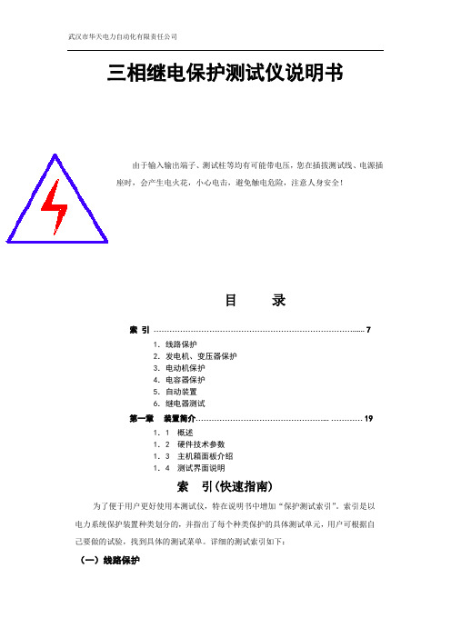
三相继电保护测试仪说明书由于输入输出端子、测试柱等均有可能带电压,您在插拔测试线、电源插座时,会产生电火花,小心电击,避免触电危险,注意人身安全!目录索引 (7)1.线路保护2.发电机、变压器保护3.电动机保护4.电容器保护5.自动装置6.继电器测试第一章装置简介 (19)1.1 概述1.2 硬件技术参数1.3 主机箱面板介绍1.4 测试界面说明索引(快速指南)为了便于用户更好使用本测试仪,特在说明书中增加“保护测试索引”。
索引是以电力系统保护装置种类划分的,并指出了每个种类保护的具体测试单元,用户可根据自己要做的试验,找到具体的测试菜单。
详细的测试索引如下:(一)线路保护(二)发电机、变压器保护(三)电动机保护(四)电容器保护(五)自动装置(六)继电器测试11.其它如:同步继电器、信号继电器、重合闸继电器等均可由程控电源菜单来完成。
第一章装置简介1.1 概述☆HTWJB-3H系列微机型继电保护测试装置是按照国家标T624-1997继电保护微机型试验装置技术条件>>设计,广泛听取用户意见,吸取当前最新电力电子技术,完全结合现场实际推出的新一代继电保护测试工具。
☆HTWJB-3H具有测试范围广、输出电流大、电压高、带负载能力强、可靠性高等特点;该系统为测试机电型、电磁型、晶体管型、集成电路型及微机型保护装置提供了高水平的校验工具。
☆HTWJB-3H系列测试软件的设计简洁明了,功能强大,参数设置可存储调用,避免了用户重复设置。
实时显示电压电流的波形图,并可存储、打印。
1.先进的硬件技术平台(1) HTWJB-3H 系统将工控机、高速信号处理器DSP、FPGA等先进技术集成(2)车载8.4TFT液晶屏可靠性高,寿命长,抗震性能好。
(3)避免了用户因存储空间不足而必须定期删除报告的麻烦。
无CF卡等电子盘容量小、易损坏的缺陷。
(4)高精度,高质量的波形。
幅频特性在0-1KHz内均保持最大平坦性。
Eaton Moeller ZB过载保护器说明书
Eaton 278467Eaton Moeller® series ZB Overload relay, ZB150, Ir= 25 - 35 A, 1 N/O, 1 N/C, Separate mounting, IP00General specificationsEaton Moeller® series ZB Thermal overload relay278467ZB150-35/KK4015082784676134 mm 121 mm 118 mm 1.394 kgUL 60947-4-1 CSA File No.: 012528 CSA-C22.2 No. 60947-4-1-14 IEC/EN 60947 UL File No.: E29184 CECSA Class No.: 3211-03 VDE 0660 IEC/EN 60947-4-1 ULUL Category Control No.: NKCR CSAProduct NameCatalog Number Model Code EANProduct Length/Depth Product Height Product Width Product Weight CertificationsReset pushbutton manual/autoPhase-failure sensitivity (according to IEC/EN 60947, VDE 0660 Part 102) Test/off button Trip-free release-25 °C55 °C-25 °C40 °C CLASS 10 A Damp heat, constant, to IEC 60068-2-78 Damp heat, cyclic, to IEC 60068-2-30IP00ZB150Separate mounting Direct attachment25 A35 AIII3Finger and back-of-hand proof, Protection against direct contact when actuated from front (EN 50274)FeaturesAmbient operating temperature - min Ambient operating temperature - max Ambient operating temperature (enclosed) - min Ambient operating temperature (enclosed) - max Class Climatic proofingDegree of protection Frame size Mounting method Overload release current setting - min Overload release current setting - max Overvoltage category Pollution degree Product category ProtectionAccessoriesOverload relay ZB up to 150 A6000 V AC4000 V (auxiliary and control circuits)10 g, Mechanical, Sinusoidal, Shock duration 10 ms Branch circuits, (UL/CSA)Continuous≤ 0.25 %/K, residual error for T > 40°1 x (0.75 - 2.5) mm², Control circuit cables1 x (4 - 70) mm², Main cables2 x (4 - 70) mm², Main cables2 x (0.75 - 2.5) mm², Control circuit cables1 x (4 - 16) mm², Main cables2 x (4 - 16) mm², Main cables2 x (0.75 - 4) mm², Control circuit cables1 x (0.75 - 4) mm², Control circuit cables3/0, Main cables2 x (18 - 14), Control circuit cables1 x (16 - 70) mm², Main cables2 x (16 - 70) mm², Main cables24 mm8 mmM10, Terminal screw, Main cables5 mm AF, Hexagon socket-head spanner, Terminal screw, Main cablesM3.5, Terminal screw, Control circuit cables1 x 6 mm, Terminal screw, Control circuit cables, Standard screwdriver2, Terminal screw, Control circuit cables, Pozidriv screwdriver1.2 Nm, Screw terminals, Control circuit cables10 Nm, Screw terminals, Main cables6 A 5 kA, SCCR (UL/CSA)60 A Class J, max. Fuse, SCCR (UL/CSA)Rated impulse withstand voltage (Uimp)Shock resistanceSuitable forTemperature compensation Terminal capacity (flexible with ferrule)Terminal capacity (solid)Terminal capacity (solid/stranded AWG) Terminal capacity (stranded)Stripping length (main cable)Stripping length (control circuit cable) Screw sizeScrewdriver sizeTightening torqueConventional thermal current ith of auxiliary contacts (1-pole, open)Rated operational current (Ie) at AC-15, 120 V Short-circuit current rating (basic rating) Short-circuit protection rating1.5 A1.5 A0.9 A0.4 A0.2 A0.9 A0.75 A1000 V440 V, Between auxiliary contacts and main contacts, According to EN 61140240 V AC, Between auxiliary contacts, According to EN 61140 440 V AC, Between main circuits, According to EN 61140B600 at opposite polarity, AC operated (UL/CSA)R300, DC operated (UL/CSA)B300 at opposite polarity, AC operated (UL/CSA)600 VAC600 VAC 100 A gG/gL, Fuse, Type “2” coordination125 A gG/gL, Fuse, Type “1” coordinationMax. 6 A gG/gL, fuse, Without welding, Auxiliary and control circuits111121 W0 W7 W35 A0 WMeets the product standard's requirements.Meets the product standard's requirements.Meets the product standard's requirements.Meets the product standard's requirements.Rated operational current (Ie) at AC-15, 220 V, 230 V, 240 V Rated operational current (Ie) at AC-15, 380 V, 400 V, 415 V Rated operational current (Ie) at DC-13, 110 VRated operational current (Ie) at DC-13, 220 V, 230 V Rated operational current (Ie) at DC-13, 24 VRated operational current (Ie) at DC-13, 60 VRated operational voltage (Ue) - maxSafe isolationSwitching capacity (auxiliary contacts, pilot duty) Voltage rating - maxVoltage rating - max Number of auxiliary contacts (change-over contacts)Number of auxiliary contacts (normally closed contacts) Number of auxiliary contacts (normally open contacts) Number of contacts (normally closed contacts)Number of contacts (normally open contacts)Equipment heat dissipation, current-dependent PvidHeat dissipation capacity PdissHeat dissipation per pole, current-dependent PvidRated operational current for specified heat dissipation (In) Static heat dissipation, non-current-dependent Pvs10.2.2 Corrosion resistance10.2.3.1 Verification of thermal stability of enclosures10.2.3.2 Verification of resistance of insulating materials to normal heat10.2.3.3 Resist. of insul. mat. to abnormal heat/fire by internal elect. effectsMeets the product standard's requirements.Does not apply, since the entire switchgear needs to be evaluated.Does not apply, since the entire switchgear needs to be evaluated.Meets the product standard's requirements.Does not apply, since the entire switchgear needs to be evaluated.Meets the product standard's requirements.Does not apply, since the entire switchgear needs to be evaluated.Does not apply, since the entire switchgear needs to be evaluated.Is the panel builder's responsibility.Is the panel builder's responsibility.Is the panel builder's responsibility.Is the panel builder's responsibility.Is the panel builder's responsibility.The panel builder is responsible for the temperature rise calculation. Eaton will provide heat dissipation data for the devices.Is the panel builder's responsibility. The specifications for the switchgear must be observed.Product Range Catalog Switching and protecting motorseaton-tripping-zb-overload-relay-characteristic-curve.epsDA-DC-00004845.pdfDA-DC-00004855.pdfeaton-tripping-devices-overload-relay-zb-overload-relay-dimensions-007.epseaton-tripping-devices-overload-relay-zb-overload-relay-3d-drawing-005.epsDA-CE-ETN.ZB150-35_KKIL03407006Zeaton-motor-protective-relay-zb65-zb150-overload-monitoring-exe-manual-mn03407005z-de-de-en-us.pdfDA-CD-zb150_kkDA-CS-zb150_kkeaton-tripping-devices-overload-relay-zb-overload-relay-wiring-diagram.eps10.2.4 Resistance to ultra-violet (UV) radiation10.2.5 Lifting10.2.6 Mechanical impact10.2.7 Inscriptions10.3 Degree of protection of assemblies10.4 Clearances and creepage distances10.5 Protection against electric shock10.6 Incorporation of switching devices and components 10.7 Internal electrical circuits and connections10.8 Connections for external conductors10.9.2 Power-frequency electric strength10.9.3 Impulse withstand voltage10.9.4 Testing of enclosures made of insulating material 10.10 Temperature rise10.11 Short-circuit rating10.12 Electromagnetic compatibility Catalogues Characteristic curve Declarations of conformity DrawingseCAD modelInstallation instructions Manuals and user guides mCAD modelWiring diagramsEaton Corporation plc Eaton House30 Pembroke Road Dublin 4, Ireland © 2023 Eaton. All rights reserved. Eaton is a registered trademark.All other trademarks areproperty of their respectiveowners./socialmediaIs the panel builder's responsibility. The specifications for the switchgear must be observed.The device meets the requirements, provided the information in the instruction leaflet (IL) is observed.10.13 Mechanical function。
- 1、下载文档前请自行甄别文档内容的完整性,平台不提供额外的编辑、内容补充、找答案等附加服务。
- 2、"仅部分预览"的文档,不可在线预览部分如存在完整性等问题,可反馈申请退款(可完整预览的文档不适用该条件!)。
- 3、如文档侵犯您的权益,请联系客服反馈,我们会尽快为您处理(人工客服工作时间:9:00-18:30)。
三相电机过载保护继电器用户手册V1.02
1.性能指标
1.工作环境:温度0~50℃,湿度﹤85%RH的无腐蚀性气体场合;
2.电流输入:三相10A(1~10A)或1A(0.1A~1A),采用用CT隔离、直接穿芯方式;
3.输出方式:一路继电器输出(常闭接点),容量大于5A/250V AC。
4.电流设定范围:1~10A或0.1~1A。
5.工作电源:20-30V AC/DC;功耗:小于3W;
6.绿色LED:运行状态指示灯(指示灯快闪频率约为3次/秒,慢闪频率约为1次/秒)。
a运行状态指示灯常亮:表示电机未工作。
b运行状态指示灯快速闪烁:表示电机
处于起动过程。
c运行状态指示灯慢速闪烁:表示电机正常运行。
7.红色LED:报警指示灯
a报警指示灯快速闪烁:表示电机电流过载。
b报警指示灯常亮:表示电机起动过
程中发生“启动超时”或者“缺相”脱扣,或是电机运行过程中发生“电流过载”
或“缺相”脱扣。
2.设置说明
三相电机过载保护继电器(以下简称装置)采用32位微电脑为核心芯片,配置一个带刻度的调节旋钮,通过旋钮设置电流限值,实时监测电机电流情况,并对异常情况进行脱扣保护处理。
正常使用前请将旋钮调整至合适范围,整定好过载保护动作电流值,如下图所示:
图一10A型过流整定旋钮图二1A型过流整定旋钮如上图一所示,过流整定旋钮调整至5A位置。
1)当电机处于正常运行状态时,电机电流超过5A且持续10秒以上,装置脱扣继电器会动作,断开电机控制回路使电机停机。
2)当启动电机时,电机的启动电流超过5A且持续30秒以上,装置脱扣继电器会动作,断开电机控制回路使电机停机。
注:脱扣后需要执行复位操作,电机才能正常工作。
过载保护只会在电机运行过程中才会投入。
一些重载起动的设备,可根据实际情况适当调高过载保护的整定值,既保证电动机安全运行,也防止出现误动的情况。
列如:现有一台正常运行额定电流值为5A的三相异步电动机,可选择AIX-10A型号的三相电机过载保护继电器,整定的过流限值为5.5A~6.5A。
3.保护功能
三相电机过载保护继电器系列产品主要分为启动超时保护,过载保护,缺相保护三大功能。
1.启动超时保护:电机启动时,启动持续大电流时间超过30S,将对电机进行脱扣停车处理;防止电机在异常启动过程中持续大电流造成的过热和绝缘降低从而烧坏电机。
2.过载保护:电机运行时,当任意相电流持续超出10S后将对电机进行脱扣停车处理;主要保护电机长期运行在额定电流以上,而造成的过热和绝缘降低从而烧坏电机。
3.缺相保护:电机启动或电机运行时,电路中任意一项电路断路后,将对电机进行脱扣停车处理;防止电机在缺相过程中持续大电流造成的过热和绝缘降低从而烧坏电机。
4.复位功能:发生报警后,即报警指示灯常亮时;按下复位键一次,执行设备复位操作,复位完成后报警指示熄灭。
4.外形尺寸与接线端子图
图三外型尺寸图四接线端子图。