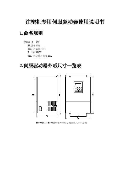
麦格米特 MV600J注塑机专用伺服驱动器用户手册V1
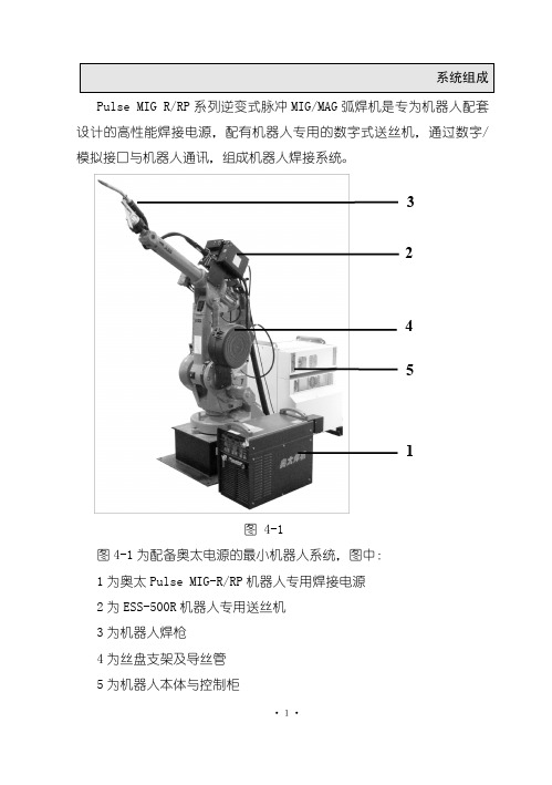
交流伺服电机驱动器使用说明书.

交流伺服电机驱动器使用说明书1 •特点16位CPU+32位DSP三环(位置、速度、电流)全数字化控制脉冲序列、速度、转矩多种指令及其组合控制转速、转矩实时动态显示完善的自诊断保护功能,免维护型产品交流同步全封闭伺服电机适应各种恶劣环境体积小、重量轻2 •指标输入电源三相200V -10%〜+15% 50/60HZ控制方法IGBT PWM(正弦波)反馈增量式编码器(2500P/r )控制输入伺服-ON报警清除CW、CCW驱动、静止指令输入输入电压土10V控制电源DC12〜24V 最大200mA保护功能OU LU OS OL OH REG OC ST CPU 错误,DSP错误,系统错误通讯RS232C频率特性200Hz或更高(Jm=Jc时)体积L250 X W85 X H205 重量3.8Kg 3•原理见米纳斯驱动器方框图(图1)和控制方框图(图2)4•接线4.1主回路卸下盖板坚固螺丝;取下端子盖板。
用足够线经和连接器尺寸作连接,导线应采用额定温度600C以上的铜体线,装上端子盖板,拧紧盖板螺丝。
螺丝拧紧力矩大于1.2Nm M4或2.0 Nm M5时才可能损坏端子,接地线径为2.0mn i 具体见接线图34.2CN SIG 连接器[具体见接线图4驱动器和电机之间的电缆长度最大20M这些线至少要离开主电路接线30cm,不要让这些线与电源进线走一线槽;或让它们捆扎在一起线经0.18mm2或以上屏蔽双绞线,有足够的耐弯曲力屏蔽驱动器侧的屏蔽应连接到CN.SIG连接器的20脚,电机侧应连接到J 脚若电缆长于10M,则编码器电源线+5V、0V应接双线4.3CN I/F 连接控制器等周边设备与驱动器之间距离最大为3M这些线至少和主电路接线相隔30cm ,不要让这些线与电源进线走同一线槽或和它们捆扎在一起COM和COM之间的控制电源(V DC)由用户供给控制信号输出端子可以接受最大24V或50mA不要施加超过此限位的电压和电流若用控制信号直接使继电器动作要象左图所示那样,并联一只二极管到继电器。
MV100麦格米特矢量控制变频器手册V1.1
无 PG 磁通矢量控制,无 PG V/F 控制 V/F 控制 2000.0Hz,矢量控制:650.0Hz 1:200(无 PG 磁通矢量控制) ±0.2% (无 PG 磁通矢量控制) ±0.3% (无 PG 磁通矢量控制) <10ms(无 PG 磁通矢量控制) 无 PG 磁通矢量转矩控制精度 7.5% 0Hz 150%(无 PG 磁通矢量控制) 飞速跟踪、转矩限制、多段速运行、自整定、跳频运行、PID 调节、瞬停不停、 三地切换、MODBUS 通讯、转矩控制、转矩及速度控制模式切换、自动重启动 功能、直流制动、能耗制动等、爬行功能 0.1Hz~2000.0Hz 0.0Hz~60.0Hz 数字面板设定,端子 UP/DN 设定,上位机通讯设定,模拟设定(AI1/AI2), 端子脉冲设定 0.1~3600.0 单位可选,0.1s,s,min 内置制动单元,制动率 0.0~100.0% 起始频率:0.0Hz~60.0Hz;
Shenzhen Megmeet Drive Technology Co., Ltd.
4
1.2 产品技术规格 各系列功率规格参数
表 1-1 三相 380V 系列功率规格参数
三相 380V 系列 变频器型号 适用电机功率 适用电机功率 输入电流 输 入 电 源 额定电压 电压变动范围 额定频率 频率变动范围 额定输出容量 额定输出电流 输 出 输出电压 输出频率范围 载波频率 过载能力 冷却方式 1.2KVA 1.5A 2KVA 2.5A MV100G-4T0.75 MV100A-4T0.4 0.4kW 0.5HP 1.9A MV100A-4T0.75 0.75kW 1HP 3.2A MV100G-4T1.5 MV100A-4T1.5 1.5kW 2HP 4.3A 3 相 380~480V ±10%(342~528V) 50Hz/60Hz ±5%(47~63Hz) 3.3KVA 4.2A 4.4KVA 5.5A 6.8KVA 8.5A MV100G-4T2.2 MV100A-4T2.2 2.2kW 3HP 7.1A 3.7kW 5HP 11.2A MV100G-4T3.7
SAMSON 伺服 技术手册600

PROP R O D U C TS P E C I F I C A T I O N S H E E TA M P L I F I E R STYPE:POWER AMPLIFIERSPRODUCTDESCRIPTIONSERVO 600POWER AMPLIFIERSERIESCATEGORYSERVO 600AMPLIFIERSFRONT PANELBACK PANELGENERAL DESCRIPTIONThe Samson Servo 600 stereo power amplifier has been designed to provide robust, clean output with low distortion and wide dynamic range, along with the dependability demanded by the most professional audio engineers and installers.The convenient 2 rack-space design is compact, and yet there’s plenty of power available, with 2 x 225 Watts at 8Ω, 2 x 300 Watts at 4Ω over the full frequency spectrum, from 10 Hz to 55 kHz.For mono applications, a Bridge mode links both channels of the amplifiers, thus providing even more single channel power, with a power rating of 600 watts into an 8 Ohm load.Input connections are available for both unbalanced RCA connections and balanced 1/4-inch TRS connections. For the outputs, the Servo 600 amplifier provides standard 5-way binding posts and 1/4” phone jacks. Front-panel controls and displays include a power switch with LED indicator, as well as independent left and right channel input level controls. To help you set the correct operating levels, the Servo 600 amplifier includes front panel Signal, Peak and Protection LED indicators. There's also a ten-segment VU meter to help you set a good operating level.Like all serious power amplifiers, the Servo 600’s internal electronics are based around a serious power-core, with an over-sized toroidal transformer and large extruded heat sink. To keep the Servo 600 amplifierrunning cool, the design employs twin internal wind tunnels with forced-air cooling via two temperature-sensitive, variable speed fans, which greatly reduce the chance of thermal and overheating problems. Multi-stage protection for power-up, over-heating, over-current, short circuit, low outputimpedance and DC voltage, assures high reliability under the most demanding situations.The Servo 600 amp is road tough with its all steel chassis and 19-inch rack mount design. The Servo 600 amplifier is ready for a life on the road, or to make its home in a fixed installation.Optimized for live sound venues, houses of worship, commercial installations, and for driving small and medium-sized live PA systems, the Servo Series amplifiers will deliver reliable power from gig-to-gig, venue-to-venue and day-to-night.FEATURES> P ower to spare - 2 x 225 Watts at 8Ω, 2 x 300 Watts at 4Ω> F or mono applications, a Bridge mode links both channelsof the amplifiers, thus providing even more power, with a power rating of 600 watts driving an 8 Ohm load.> C lean, crisp sound - Impressive audio specifications suchas 0.04% THD, dynamic range of 105 dB, crosstalk of 80 dB, and frequency response of 10 Hz to 55 kHz guarantee ultra-clean sound quality.> I ndependent input level controls for each channel allowprecision adjustments.continues»©2006 Samson v1.0 5/06SERVO 600 PRODUCT SPECIFICATION SHEETSERIES DESCRIPTION CATEGORYSERVO 600POWER AMPLIFIER AMPLIFIERSARCHITECT’S & ENGINEER’S SPECIFICATIONSThe Samson Servo 600 shall be a two space, rackmount stereo power amplifier. It shall deliver 300 watts per channel at 4 Ohms or 600 watts into 8 Ohms in bridge mono mode. It shall have 1/4 inch balanced inputs and RCA unbalanced inputs. It shall be a bi-polar design and use a toroidal transformer. The front panel shall have volume controls and LED metering for each channel. The rear panel shall also have 5 way binding posts for the amplifier outputs.SERVO 600 SPECIFICATIONSStereo both channel driven8 Ohms ..............................225 Watts x 24 Ohms ..............................300 Watts x 2Bridged mono8 Ohms ..............................600 WattsSignal to Noise Ratio (20Hz-20k) ......104dBDistortion (SMPTE-IM) .....................0.04%Input sensitivity @8 Ohms ................1.24V(4dBu)Voltage Gain....................................34dBOutput Circuitry Class.......................ABAC Power@1/8 rated power 4 Ohms, max. .......1.3A@1/3 rated power 4 Ohms, max. .......3.3A@ rated power 4 Ohms, max. ............10ADistortion (typical @4 Ohms)20Hz-20kHz,10dBbelow rated power ...............0.03%IkHz,rated power .................0.1%Frequency Response@8 Ohms 1Watt, 20Hz-20kHz ..........0/-0.5dBDamping Factor (400Hz) (350)Input Impedance ..............................15k Ohm Unbalanced,30k Ohm BalancedInput Clipping ..................................10 Vrms(22dBu) Cooling...........................................C ontinuously variable speed,fan forced airConnectors (each channel)Input .................................R CA unbalanced and1/4”(6.3mm)TRS, balanced Output ...............................5-way Binding post and1/4” Phone Controls..........................................A C power switch, Channel 1and 2 volumeIndicators .......................................P ower on (blue), Protection(amber), Signal (green) foreach Ch., Peak(red) for eachCh. Level: , -24 dB, -20 dB,-16 dB, -12 dB, -8 dB, -4dB, -2 dB, O, +2 dB and+4 dB (PEAK). Protection.......................................S hort circuit, Thermal,Currentlimit,DC offset,Current inrush,RF protection, Turn on/Turnoff mutingPower Requirements.........................115/230,240VAC,50/60Hz Dimensions (W x H x D) ....................19” x 3.5” x 11.7”(483mm x 89mm x 297mm) Net Weight ......................................24 lbs (10.91 kg)FEATURES(continued)>10 segment LED signal indicators for each channel continuously display power output levels and allow you to correct for overloading (clipping) conditions.>U nique stable bipolar circuit design that continuously keeps DC output during idling at or near zero volts (thus keeping idle speakers at their zero point). This serves to minimize heat overload problems by effectively preventing the Servo 600 from applying power when unnecessary.>F orced air cooling via two temperature-sensitive, variable speed fans provides reliable performance without thermal and overheating problems.>P rotection relay circuitry (with dedicated LEDs for each channel) that guards against overheating or faulty wiring conditions and also prevents “thumps” when powering on or off. This means that you can use the Servo Series with a single power strip into which a mixer or other audio devices are connected, without danger of damage to connected speakers. >I nput connectors for each channel accommodate both RCA or balanced 1/4-inch TRS plugs.>O utput connections are made via 5-way binding posts.>T oroidal transformer power supply for high current and low profile. >T he Servo 600 can be mounted in any standard 19" rack (taking just two rack spaces), making it easy to integrate the amp into any fixed or traveling PA rig.>R ugged construction (an all-steel chassis with a cool gray finish and a lightweight anodized aluminum heat sink) makes the Servo 600 eminently roadworthy.>E xtended three-year warranty.。
中联中科PLC5613-6-麦格米特说明

电器动作
更换之
了
断路器 QF1-3 跳闸 重新合闸
9
DSJ680EPEP-P 塔机电控系统使用说明书
第二章 常见故障及对策
由于本系统采用了可编程控制器进行中央控制,省去了大量的用 于逻辑控制的中间继电器,从而大大提高了整个系统的可靠性,也使 故障的定位和排除更加方便。
可编程控制器的控制方式是这样的: 所有的信号(包括联动台发出的控制信号和各种报警信号)均通
三、 自动空气开关的操作
只有在现场准备就绪,司机就位,需要作业时,才能 合上空气开关。合开关前先应检查电压表的读数看是否正常。 空气开关位于小驾配箱的下部。其操作手柄暴露在箱门外, 便于司机操作。当将手柄往上板,开关合上;往下板开关切 断。塔机除照明外所有机构、控制箱柜等的电源均由此空气 开关控制。
驾驶员下班时必须将“回转—制动”开关扳至“回转” 位置,以免蓄电池过度放电造成损坏。
四、行走操作 (选配)
行走操作由右联动台上的手柄控制。将此手柄往左扳,大 车前行,往右扳大车后行。手柄左右方向各分两档,对应于从 低到高两种行走速度。启动时,应先从手柄中位扳到低速档, 然后再扳到高速档;停止时,应先从高速档回到低速档,然后 再回到停止档位。
当起重力矩超过最大允许值时电控系统会作如下反应: 右联动台上的红色“超力矩”报警灯闪烁 右联动台内的蜂鸣器发出连续的“嘀嘀嘀嘀”四声报警声 主钩的上升运动被禁止 小车的向外运动被禁止
解除办法: 向内变幅。
2、超重量信号:
当起重量超过最大允许值时电控系统会作如下反应: 右联动台上的红色“超重量”报警灯闪烁 右联动台内的蜂鸣器发出连续的“嘀嘀嘀”三声报警声 主钩的上升运动被禁止
当塔机运行遇到危急情况,来不及按正常程序停 车时,或操作手柄失控时,必须立即按下急停按钮! 而非紧急情况下,不得使用急停按钮作正常停车用。 否则会产生很大的冲击。
SCHUNK 铭记 Gripper 驱动器 GM 1说明书

Gripper actuator GMDear Customer,Congratulations on choosing a SCHUNK product. By choosing SCHUNK, you have opted for the highest precision, top quality and best service.You are going to increase the process reliability of your production and achieve best machining results – to the customer's complete satisfaction.SCHUNK products are inspiring.Our detailed assembly and operation manual will support you.Do you have further questions? You may contact us at any time – even after purchase. You can reach us directly at the mentioned addresses in the last chapter of these instructions.Kindest Regards,Your SCHUNK GmbH & Co. KG Precision Workholding Systems Bahnhofstr. 106 - 134 D-74348 Lauffen/ NeckarTel. +49-7133-103-2503 Fax +49-7133-103-2189********************.com Document last updated: 18.02.2008G RIPPER ACTUATORT YPESGM 280 TO GM 400Contents1SAFETY (3)1.1S YMBOL K EY (3)1.2A PPROPRIATE U SE (3)1.3S AFETY N OTES (4)1.4I NDICATIONS TO THE OPERATING MANUAL (4)2WARRANTY (5)3SCOPE OF DELIVERY (5)4TECHNICAL DATA (5)5OPERATING AND ENVIRONMENTAL CONDITIONS (5)6ASSEMBLY AND INSTALLATION (6)6.1D ESIGN PRECAUTIONS (6)6.2C OMPRESSED AIR SUPPLY (6)6.3S PECIAL CONNECTING MEASURES (6)6.4A SSEMBLY MEASURES (7)6.5M EASURES FOR THE INITIAL OPERATION (7)7HANDLING (8)7.1G RIP FORCE SAFETY DEVICE (8)7.2C ONTROL OF GRIP FORCE SAFETY DEVICE (8)7.3E ND POSITION INTERROGATION (9)8EC DECLARATION OF INCORPORATION (13)9CONTACT (14)Gripper actuator GM1 Safety1.1 Symbol KeyYou will find this symbol wherever hazards for persons or damage to the productare possible.This symbol indicates important information on the product or its handling.1.2 Appropriate UseThe unit must only be used within the scope of its technical data. Appropriate use also includes compliance with the conditions the manufacturer has specified for commissioning, assembly, operation, environment and maintenance. Using the unit with disregard to even a minor specification will be deemed inappropriate use. The manufacturer assumes no liability for any injury or damage resulting from inappropriate use.The gripper actuators are manufactured in accordance with the current level of technology and with recognised safety regulations. During their use, however, there may occur risks to life and limb of the user or impairment of the portal actuator and other material assets.The gripper actuators are intended exclusively for the parallel gripping of service loads in any position that do not react in their manipulation with any risk to persons, property or the environment.The maximum permissible service loads and forces are given in our standard catalogue.Any usage beyond these definitions is inappropriate.The manufacturer cannot be held liable for loss or damage arising therefrom. The risk is borne exclusively by the user.The gripper actuator must only be operated by persons that arefamiliar therewith and that have been instructed in the associated hazards. The relevant acci-dent prevention regulations and the other generally recognised safety and occupational health regulations must be complied with.Gripper actuator GM1.3 Safety Notes1.Responsibility for the compatibility of pneumatic equipment lies with the person who designs the pneumatic system or takes the decision on its specifications.- Since the products specified herein can be used under various operatingconditions, their compatibility with the appropriate pneumatic system must be based on specifications and/or tests in order to conform to their requirements.2.Machines and equipment operated by pneumatic means may only be used by trained personnel.- Compressed air can be hazardous if an operator is not familiar with its use.The assembly, handling or repair of pneumatic systems is to be undertakenby trained and experienced personnel.3. Do not carry out maintenance work on machines and equipment and do not at-tempt to remove components until it has been confirmed that it is safe to do so.- Inspection and maintenance of machines and equipment may only becarried out after it has been confirmed that the devices that must be swit-ched off are in a securely deactivated condition. - If machine parts must be removed, carry out safety precautions asmentioned above. Deactivate the compressed air supply to this machine and release any remaining compressed air from the system. - Before machines and equipment are switched on again, take measures toensure that cylinder rods etc. are not pushed outwards. Allow compressed air to enter the system slowly so that counterpressure builds up gradually.4. Contact SCHUNK (see chapter 12 page 13) if the product is to be used under oneof the following conditions:- Conditions and environments that lie outside the stated specifications, orwhere the product is to be used outdoors. - Installation in equipment in conjunction with nuclear power, railways, aero-space, vehicles, medical equipment, food and drink, leisure equipment,emergency shutdown circuits, applications in presses or safety equipment. - Any application that may possibly have negative influences on persons,animals or property and that requires a special safety analysis.5. This user manual should always be easily accessible.1.4 Indications to the operating manualThis user manual describes gripper actuators of series GM 280, GM 300 and GM 400. All statements in this user manual refer to the types stated above.Gripper actuator GM2 WarrantyThe warranty period is 24 months or 40 million load cycles after delivery date from the factory, assuming use in single-shift operation and that the recommended maintenance and lubrication intervals are respected. Components that come into contact with workpieces, wearing parts, shock absorbers, stop screws and proximity switches are never included in the warranty.The warranty covers the replacement or repair of defective parts in the manufacturing plant. Further claims are hereby excluded. In this context, please also see our General Terms and Conditions.3 Scope of DeliveryThe scope of delivery comprises- Gripper actuator GM, depending on the version ordered4 Technical DataPlease consult our catalogue for further technical details. The last version is valid in each case. (in accordance with Chapter 2.3 General Terms and Conditions)The airborne sound emitted from the unit is <= 70dB(A)5 Operating and environmental conditions- Do not use the product in environments comprising corrosive gases, salt water, water or vapours.- For use in an atmosphere where water drops, oil, sprays etc, occur take appropriate countermeasures in order to ensure protection.- If electronic end switches are to be used, these should not be used in the presence of strong magnetic fields.- Please contact SCHUNK (see chapter 12 page 13) if the product is to be used in the presence of strong magnetic fields.- Do not use the gripper actuator in an atmosphere in which it could come into contact with fluids such as oil or water.- Do not use the gripper actuator in an atmosphere in which it could come into direct contact with substances such as powder dust, dust, sprays etc.- Do not use the gripper actuator in an atmosphere in which sources of heat are present.- Do not subject the gripper actuator to excessive vibrations and/or shocks.Gripper actuator GM6 Assembly and Installation6.1 Design precautions- A protective guard is recommended in order to minimise the risk of injury.- Ensure that loose, fixed and/or connected parts or tightened securely.- Take account of the possibility that the operating pressure may decrease as a result of power failures etc.- Pay attention to the possibility of the failure of power supplies.- Mount the compressed air supply in such a way as to prevent a gripping action.- Pay attention to emergency shutdown facilities.- Pay attention to what will happen after an emergency stop or abnormal stoppage.Ensure that nobody can be placed at risk or be injured when equipment is restarted.6.2 Compressed air supply- Use clean compressed air and insert a filter between the supply and the pneumatic system.- Install a water separator in the pneumatic system.- Use the product only within the range specified for the medium temperature and am-bient temperature.Air specification- dry (free from condensation)- filtered to 10 microns- oiled or oil-free6.3 Special connecting measures- Use connecting pipes of a cross-section that is larger than or identical to that of the connector thread.- Blow air through the connecting pipes before fitting the devices in order to remove any dust, contaminant or particles.- Avoid the ingress of sealing material into the pipe network.- Do not remove pneumatic components from their packaging until shortly before fitting.Gripper actuator GM6.4 Assembly measures- During the mounting of the gripper actuator or gripper jaws on the gripper actuator, do not allow the system to be subjected to impermissible forces or moments.- The flatness of the mounting surfaces must be less than 0.02mm.- Select the correct means of connection with a load that has its own guidance mechanism and ensure that this is adequately aligned.- Avoid contact with the gripper actuator during operation.- Select a suitable screw tightening torque for mounting of the gripper actuator or loads on the gripper actuator in accordance with the generally valid guidelines for screwconnections.6.5 Measures for the initial operationPlease read this user manual carefully. Knowledge of this user manual is essential inorder to prevent errors and ensure problem-free operation.Under no circumstances may gripper actuators be operated with oiled air if theyare subsequently to be operated with oil-free air.- Check the technical specifications.- Do not use the device until you have checked that it functions correctly taking account of all permissible operating parameters.- Regulate the operating speed of the cylinder by means of throttle type non-return valves. Increase from the low speed to higher speeds until the required operatingspeed is reached.Selection and dimensioning- Do not subject the units to loads that exceed the limits of their operating range. If excessive loads are applied , the gripper jaw guidance system and closing mechan-ism could suffer damage or inaccuracies. The maximum permissible loads are givenin our standard catalogue.- Do not allow the system to experience impermissible forces or shocks and do not use excessively long gripper jaws. The maximum permissible gripper jaw length is givenin our standard catalogue.Gripper actuator GM7 Handling7.1 Grip force safety deviceIn order to secure the grip force in the event of pressure loss, an additional module can be fitted without the need for further accessories.- GKS 280 for gripper actuator GM 280- GKS 300 for gripper actuator GM 300- GKS 400 for gripper actuator GM 400Figure 1: grip force safety deviceIf a gripper actuator including a grip force safety device as described in our standard catalogue is ordered, it is supplied with the spring already installed by SCHUNK.7.2 Control of grip force safety deviceThe grip force safety device can be controlled by 2 methods.The grip forces are given in our standard catalogue.Connection diagram 1 Connection diagram 2Figure 2: Control of grip force safety deviceConnection scheme 1:- The grip force safety device is added up to the gripper actuator grip force. Connection scheme 2:- The grip force of the gripper actuator is not influenced by the grip force.Gripper actuator GM7.3 End position interrogationStandardised interrogation sets for direct mounting are available for interrogation of end positions.- Proximity switch - complete GMNS-...The scope of delivery includes:- 1x retaining plate - 1x proximity switch - 1x connection cableFigure 3: position from the proximity switchAfter the clamping screw has been loosened, the proximity switch can be set by means of the retaining plate. Interrogation is carried out on an integral switching pin. Installation of 2 interrogation sets is possible as illustrated, allowing interrogation of both end positions.8RepairsThe repair or elimination of defects on our products by the customer may only be car-ried out with our explicit written agreement. Any failure to adhere to this principle ren-ders invalid our warranty and liability for any resulting warranty or secondary losses.Following receipt and examination, all gripper actuators of series GM can be repaired bySCHUNK.Proximity switch (GMNS-...)Gripper actuator GM9Response to malfunctionsMalfunctions that are caused by defective components may only be remedied by replacement of these components.Defective components may only be replaced by SCHUNK genuine replacement parts.10 Maintenance and Care- The integral cylinders are lubricated for life and do not require relubrication. Opera-tion with oiled or oil-free compressed air is permissible without restrictions.- The complete mechanism is already lubricated. It is not therefore necessary to lubri-cate this again before operation.Lubrication or relubrication of the mechanism with rolling bearing grease is recom-mended after approx. 4 million cycles.- All gripper actuators of series GM are maintenance-free. In order to achieve the max-imum operating life, this chapter and chapter 6.2 (at page 6) of this user manualshould be observed.- Apart from normal cleaning of machines, no further maintenance measures arenecessary.Gripper actuator GM11 Replacement partsAs standardised wear part sets, seal sets are available. The scope of delivery includes all seals.Ordering numbers of the seal sets:- GMDI 280 (for gripper actuator GM 280)- GMDI 300 (for gripper actuator GM 300)- GMDI 400 (for gripper actuator GM 400)In accordance with the section drawing below, all other wear parts and individual parts are available as single items.Ordering numbers are as indicated in the following example- Part No. 1 GM 300-01Figure 4: section drawing GM 280, 300, 400Gripper actuator GM12 EC declaration of incorporationIn terms of the EC Machinery Directive 2006/42/EC, annex II BManufacturer/ distributorSCHUNK GmbH & Co. KG. Spann- und Greiftechnik Bahnhofstr. 106 – 13474348 Lauffen/Neckar, GermanyWe hereby declare that the following product:Product designation 2-Finger Angular Parallel Gripper, Gripper for small components Type designation: GM 280...GM 400 ID number: 0313087 (0313528)meets the applicable basic requirements of the Directive Machinery (2006/42/EC).The incomplete machine may not be put into operation until conformity of the machine into which the incomplete machine is to be installed with the provisions of the Machinery Directive (2006/42/EC) is con-firmed.Applied harmonized standards, especially:EN ISO 12100-1 Safety of machines - Basic concepts, general principles for design -- Part 1: Basic terminology, methodologyEN ISO 12100-2 Safety of machines - Basic concepts, general principles for design -- Part 2: Technical principlesThe manufacturer agrees to forward on demand the special technical documents for the incomplete ma-chine to state offices.The special technical documents according to Annex VII, Part B, belonging to the incomplete machine have been created.Person responsible for documentation: Mr. Michael Eckert, Tel.: +49(0)7133/103-2204Location, date/signature: Lauffen, Germany, January 2011p.p.Title of the signatoryDirector for DevelopmentGripper actuator GM13 ContactGERMANY – HEAD OFFICE SCHUNK GmbH & Co. KG Spann- und Greiftechnik Bahnhofstrasse 106 – 134 D-Lauffen/Neckar Tel. +49-7133-103-0 Fax +49-7133-103-2399 **************.com CANADASCHUNK Intec Corp. 190 Britannia Road East, Units 23-24Mississauga, ON L4Z 1W6 Tel. +1-905-712-2200 Fax +1-905-712-2210 **************.com DENMARKSCHUNK Intec A/S Storhaven 7 7100 VejleTel. +45-43601339 Fax +45-43601492 **************.com HUNGARYSCHUNK Intec Kft. Széchenyi út. 70. 3530 MiskolcTel. +36-46-50900-7 Fax +36-46-50900-6 **************.comAUSTRIASCHUNK Intec GmbH Holzbauernstr. 20 4050 TraunTel. +43-7229-65770-0 Fax +43-7229-65770-14 **************.com CHINASCHUNK GmbH & Co.KG ShanghaiRepresentative Office 777 Zhao Jia Bang Road Pine City Hotel, Room 923 Xuhui District Shanghai 200032Tel. +86-21-64433177 Fax +86-21-64431922 **************.com FRANCESCHUNK Intec SARL Parc d´Activités des Trois Noyers 15, Avenue James de RothschildFerrières-en-Brie77614 Marne-la-Vallée Cedex 3Tel. +33-1-64 66 38 24 Fax +33-1-64 66 38 23 **************.com INDIASCHUNK India Branch Office # 80 B, Yeswanthpur Industrial Suburbs, Bangalore 560 022 Tel. +91-80-41277361 Fax +91-80-41277363 **************.comBELGIUM, LUXEMBOURG SCHUNK Intec N.V./S.A. Bedrijvencentrum Regio Aalst Industrielaan 4, Zuid III 9320 Aalst-Erembodegem Tel. +32-53-853504 Fax +32-53-836022 **************.com CZECH REPUBLIC SCHUNK Intec s.r.o. Ernsta Macha 1 643 00 BrnoTel. +420-545 229 095 Fax +420-545 220 508 **************.com GREAT BRITAIN, IRELAND SCHUNK Intec Ltd.Cromwell Business Centre 10 Howard Way, Interchange ParkNewport Pagnell MK16 9QS Tel. +44-1908-611127 Fax +44-1908-615525 **************.com ITALYSCHUNK Intec S.r.l. Via Barozzo22075 Lurate Caccivio (CO) Tel. +39-031-4951311 Fax +39-031-4951301 **************.com Gripper actuator GMJAPANSCHUNK Intec K.K. 45-28 3-Chome Sanno Ohta-Ku Tokyo 143-0023 Tel. +81-33-7743731 Fax +81-33-7766500********************.jp www.tbk-hand.co.jpPOLANDSCHUNK Intec Sp.z o.o. Stara Iwiczna,ul. Słoneczna 116 A 05-500 Piaseczno Tel. +48-22-7262500 Fax +48-22-7262525 **************.com SOUTH KOREASCHUNK Intec Korea Ltd. # 907 Joongang Induspia 2 Bldg.,144-5 Sangdaewon-dong Jungwon-gu, Seongnam-si Kyunggi-do, 462-722 Tel. +82-31-7376141 Fax +82-31-7376142 **************.com SWITZERLAND, LIECHTENSTEIN SCHUNK Intec AG Soodring 19 8134 Adliswil 2Tel. +41-44-7102171 Fax +41-44-7102279 **************.com MEXICO, VENEZUELA SCHUNK Intec S.A. de C.V.Av. Luis Vega y Monroy # 332 Fracc. Plazas de Sol Santiago de Querétaro, Qro. 76099Tel. +52-442-223-6525 Fax +52-442-223-7665 **************.com PORTUGALSales Representative Victor MarquesTel. +34-937-556 020 Fax +34-937-908 692 Mobil +351-963-786 445**************.comSPAINSCHUNK Intec S.L. Foneria, 2708304 Mataró (Barcelona) Tel. +34-937 556 020 Fax +34-937 908 692 **************.com TURKEYSCHUNK IntecBağlama Sistemleri veOtomasyon San. ve Tic. Ltd. Şti.Küçükyali Iş Merkezi Girne MahallesiIrmak Sodak, A Blok, No: 9 34852 Maltepe, Istanbul Tel. +90-216-366-2111 Fax +90-216-366-2277 **************.com NETHERLANDSSCHUNK Intec B.V. Speldenmakerstraat 3d 5232 BH ‘s -Hertogenbosch Tel. +31-73-6441779 Fax +31-73-6448025 **************.com SLOVAKIASCHUNK Intec s.r.o. Mostná 62 919 01 NitraTel. +421-37-3260610 Fax +421-37-6421906 **************.com SWEDENSCHUNK Intec AB Morabergsvägen 28 152 42 SödertäljeTel. +46-8 554 421 00 Fax +46-8 554 421 01 **************.com USASCHUNK Intec Inc. 211 Kitty Hawk Drive Morrisville, NC 27560 Tel. +1-919-572-2705 Fax +1-919-572-2818 **************.com Gripper actuator GM。
麦格米特机器人配套焊机简易操作说明-ABB V1.3
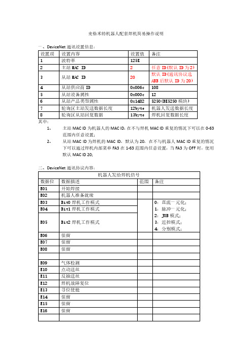
麦格米特机器人配套焊机简易操作说明其中:1、主站MAC ID为机器人的MAC ID,在不与焊机MAC ID重复的情况下可以在0-63范围内任意设置;2、从站MAC ID为焊机的MAC ID,默认为20,在不与机器人MAC ID重复的情况下可以通过焊机内部菜单FA3在1-63范围内任意设置,当FA3为OFF时,使用默认MAC ID 20;三、参数配置曲线:1、给定电流对应关系为1:1,最小限幅值为30A,最大限幅值为500A:2、给定电压对应关系为1:10,最小限幅值为12V,最大限幅值为45V:3、一元化给定电压修正值,以30V为中心点,12V为-30%,45V为+30%,最小限幅值为12V,最大限幅值为45V:4、实时焊接电流反馈,对应关系为1:1:1:10:1:100:四、焊机操作模式:焊机的操作模式由机器人下发的指令(E03-E05)决定,分为五种操作模式:1、直流一元化模式;2、脉冲一元化模式;3、JOB模式;4、近控(自由)模式;5、分别模式;五种模式下的操作方式如下:先选择机器人型号及通讯协议种类,进入内部菜单FA9选择2:ABB-麦格米特通讯协议;1、直流一元化模式:E03-E05:输入0则选择直流一元化模式/直流协同模式;参照配置曲线配置好对应参数过后,E33-E48:输入给定电流;E49-E64:输入给定电压,折算一元化电压修正值;该模式下除焊接方法锁定在直流(无法选择脉冲和双脉冲选项)以外,其他参数和选项均可以自由设置;机器人下发的给定参数为电流和电压,其中一元化修正值通过电压去计算(以30V为中心点,12V为-30%,45V为+30%),再根据电流去计算修正后的一元化电压值;该模式下无法进行存储、调用操作,也无法通过显示面板去调节给定电流电压;2、脉冲一元化模式:E03-E05:输入1则选择脉冲一元化模式/脉冲协同模式;参照配置曲线配置好对应参数过后,E33-E48:输入给定电流;E49-E64:输入给定电压,折算一元化电压修正值;该模式下除焊接方法锁定在脉冲和双脉冲(无法选择直流选项)以外,其他参数和选项均可以自由设置;机器人下发的给定参数为电流和电压,其中一元化修正值通过电压去计算(以30V为中心点,12V为-30%,45V为+30%),再根据电流去计算修正后的一元化电压值;该模式下无法进行存储、调用操作,也无法通过显示面板去调节给定电流电压;3、JOB模式:E03-E05:输入2则选择JOB模式;E17-E24:输入JOB号,调用对应JOB号内存储的参数;如果JOB号内没有参数将无法开始焊接,如果在焊接过程中切换到一个没有存储参数的JOB号则进行收弧操作结束焊接;该模式下仅能通过机器人下发JOB号后去调用已经存储好的参数,无法进行存储、调用操作,也无法通过显示面板去调节任何参数;4、近控(自由)模式:E03-E05:输入3则选择近控模式/自由模式/无焊接参数模式;该模式下只能通过显示面板去调节给定电流/送丝速度、电压/一元化修正值,可以设置所有参数和选项,同时可以进行存储、调用操作;5、分别模式:E03-E05:输入4则选择分别模式;参照配置曲线配置好对应参数过后,E33-E48:输入给定电流;E49-E64:输入给定电压;该模式下除了无法手动选择一元化(双脉冲只有一元化模式)以外,所有参数和选项均可以自由设置;机器人下发的给定参数为电流和电压,显示面板上选择分别时接收的为电流和电压;该模式下无法进行存储、调用操作,也无法通过显示面板去调节给定电流电压;五、其他功能1、机器人DO信号E01开始焊接指令,用以启动焊接和停止焊接的控制;E02机器人准备就绪,用于机器人下发自身的故障状态,用以控制焊机紧急停机;E09气体检测;E10点动送丝;E11反抽送丝;E12焊机故障复位,机器人可以通过该指令恢复E6等故障;E13寻位使能,用于使能寻位模块输出寻位电压并开启寻位功能;2、机器人DI信号A01起弧成功信号,焊机输出电压并等电弧稳定后,该位置1;A03焊接状态信号,从提前送气至回烧结束阶段,该位置1;A06焊机故障信号,焊机报故障后,该位置1,直至故障清除后清零;A07通讯就绪信号,通讯模块与机器人建立通讯后,该位置1;A09-A16焊机故障代码,焊机报故障后,返回对应的故障代码;A25寻位成功信号,该位必须在寻位使能才有效,寻位成功后该位置1;A28送丝机构正常信号,送丝机侧故障E13(电机过流)、E14(气阀故障)、E17(码盘故障)时清零,否则置1;A32给定范围超限,机器人下发给定数据超过焊机范围后置1;A33-A48焊接实时电流,焊接过程中实际输出电流;A49-A64焊接实时电压,焊接过程中实际输出电压;。
MV2V操作说明

MV2V操作说明I.主控制⾯盤 (2)I-1.全視圖 (2)I-2.電源控制 (3)I-3.操作控制 (4)I-4.鍵盤 (6)II.副控制⾯盤 (7)III.後控制⾯盤 (12)IV.操作螢幕 (13)IV-1.⽣產開始螢幕 (13)IV-2軌跡球使⽤ (21)V.開關機程序 (22)V-1.開機 (22)V-2.關機 (24)VI.換線程序 (24)VI-1.回原點 (25)VI-2.取出SUPPORT PIN (26)VI-3.程式選擇及軌道調整 (27)VI-4.基板制⽌器(PCB STOPPER) (32) VI-5.SUPPORT PIN 安裝 (32)VI-6.基板傳送檢查 (34)I.主控制⾯盤I-1.全視圖1.顯⽰區(DISPLAY)顯⽰動作時螢幕2.電源控制(POWER CONTROLS)有關於電源開關組成,包含MAIN-CPU及OPERATION READY3.操作控制(OPERATION CONTROLS)包含START,STOP ,TEACHING 鍵以及軌跡球其是為了將指標移動於全螢幕上4.軟性磁碟機(FLOPPY DISK)作為磁碟⽚和機器之間儲存或傳送資料⽤5.鍵盤(KEYBOARD)作為輸⼊數字及⽂字於程式I-2.電源控制1.SERVO MOTOR(伺服⾺達)開關伺服⾺達電源ON/OFF。
ON:伺服鎖定。
OFF:伺服鎖定解除當SERVO MOTOR開關為OFF時,則XY,ZA,ZB及其它為伺服⾺達所控制之軸皆可⽤⼿移動,若將開關轉回ON時,則將會回到其原來位置(此情況為RESET 鍵沒有於那時間被按下)2.FRONT OPERATION(前⽅操作)顯⽰操作權為前⽅或後⽅。
亮:表⽰為前⽅控制盤可操作。
滅:表⽰後⽅控制盤可操作3.MAIN CPU(主要中央處理器)NEW MMI系統之電源開關4.POWER ON(電源指⽰燈)指機器電源指⽰,亮時表⽰有供應電源,滅時表⽰無電源供應5.OPERATION READY ON(運作準備ON)開啟機器電源開關6.OPERATION READY OFF(運作準備OFF)關閉機器電源開關I-3.操作控制1.START(開始)使⽤於開始⽣產⽤2.STOP(停⽌)使⽤於暫停⽣產⽤(燈亮時),再按⼀次就會將其釋放當STOP鍵亮時,按START鍵機器僅會執⾏程式之⼀⾏動作3.RESET(重置)此鍵依據下列各種狀況使⽤之。
MOTEC_α系列伺服使用手册v1[1].1
![MOTEC_α系列伺服使用手册v1[1].1](https://img.taocdn.com/s3/m/4d450783d4d8d15abe234e4e.png)
MICRO STEP系列伺服驱动器说明书

驱动器关机后,至少一分钟以上才能再开机。
3
斯达微步伺服
第二章:连接与接线
Microstep
【连接注意事项】
● 装配、接线及检查,必须在电源切断 10 分钟后进行,以防电击; ●驱动器和伺服电机必需良好接地,接地电阻不大于 100Ω; ●电源线、电机相线和接地线,要求线径≥1.5mm2,注意:接线线头不可镀锡,一般采用导线压片接入,务必连
【安装要求】
安装驱动器应符合上述《环境条件》要求,留有足够的空间以保证降温,参见下图。控制柜应安装风扇,使 内部的温度分布均匀。驱动器应可靠接地以免触电,驱动器正面的散热器上备有二个保护性接地端子。
≥100mm
≥100mm
≥50mm
≥50mm
≥100mm
à à
≥100mm
通风方向
通风方向
驱动器安装尺寸,参见〈驱动器型号〉表格
安装尺寸 mm 145×33,Φ5 167×60,Φ5 167×73,Φ5 167×73,Φ5
重量 Kg 0.8Kg 1.5Kg 1.7Kg 1.7Kg
【环境条件】
项目
使用温度 使用湿度 储运温度 储运湿度
振动 海拔高度
条件 驱动器结构不是防水的,所以须存储或使用在室内或控制柜内淋不着雨和晒不到 太阳的地方 驱动器为精密电子仪器,请存储或使用在无腐蚀性气体、无可燃气体、无金属粉 尘、无研磨液、无油污和无微粒侵袭的通风良好、无潮无尘的地方。 0 ~ 55℃(无冰冻)
+5V A+ AB+ BZ+ ZU+ V+ W+ GND PE
编码器通信线
电机相线
U V W
外部放电电阻 Rb
迈信电气刀架伺服使用说明书
注塑机专用伺服驱动器使用说明书

HZ: 频率单位 RMP:转速单位
A: 电流单位 %:百分数
V: 电压单位
4.2 数码显示区
5 位 LED 显示,可显示设定频率、输出频率,各种监视数据以及报警代码等。 键盘按钮说明:
按键 MODE ENTER
名称 模式键 确认键
功能 一级菜单进入或退出 逐级进入菜单画面、设定参数确认
∧ ∨ << >> RUN STOP/RESET
0:非油压控制方 式
电 机 温 度 保 护 , 支 持 PTC130 , PTC150 等 最高通讯速度 1Mbps 由控制板上的 J8 跳线选择是否连 接终端匹配电阻 由控制板上的 J5 跳线选择是否连 接终端匹配电阻(预留功能) 输出范围:0mA~20mA 或者 0~10V 由控制板上 J10 选择输出模式 输出范围:0mA~20mA 或者 0~10V 2. 由控制板上 J11 选择输出模式 触点驱动能力: 1. AC250V, 3A 2. DC30V,1A
3.2.4 旋转变压器端子 CN1 信号
编号 1 2 3 4 5 9
颜色 红 蓝 白 棕 黄 绿
名称 EXC /EXC SIN SINLO COS COSLO
功能 激励信号
SIN 反馈信号
COS 反馈信号
3.3 跳线功能说明
跳线 序号
J1 J2 J6 J7 J8
J9
跳线位置
功能说明
跳线位置
功能说明
112A
20A 26A 34A 38A 46A 62A 76A 92A 113A
一个电机 PTC 保输入端子 五个数字量输入端子,可兼容 NPN,PNP 输入方式 三个模拟量输入端子,其中 AI1,AI2 只能输入电压信号,AI3 可输入电压或者电 流信号 三个继电器输出端子,一个 NO/NC 可选,两个 NO 两个模拟量输出端子,分别可选 0mA~20mA 或者 0~10V CAN 通讯端子 RS485 通讯端子(预留) 10V 电源输出 13V 电源输出 显示参数 9 个按键, 2000m 以下 室内,避免阳光直射,无腐蚀,易燃性气体,无油雾,水蒸汽等 -10℃~40℃ 小于 0.6g -20℃~60℃
Pulse MIG R系列说明书
质量完美。
十二、 软开关逆变技术,可提高整机可靠性、节能省电。
十 三 、 双脉冲功能可获得美观的鱼鳞纹状焊缝外观。
该系列焊机的制造符合标准 GB15579.1-2004《弧焊设备
第一部分:焊接电源
Pulse MIG R/RP 系列焊机焊接材料选择指南如表 5-3 所示。
表 5-3
焊接方法
焊 丝 类 型 直径(毫米)
不锈钢 碳钢
硅青铜 铝青铜
碳钢
Φ0.8、 Φ1.0、 Φ1.2、 Φ1.6
Φ1.2、 Φ1.6 Φ1.0、 Φ1.2、 Φ1.6 Φ0.8、 Φ1.0、 Φ1.2、 Φ1.6
304、308、309、316 等奥氏体不锈钢焊丝
97.5%Ar +2.5%CO2
82%Ar E70
+18%CO2
HS211
100%Ar
功率因数
表 5-2
Pulse MIG-350R/RP Pulse MIG-500R/RP
三 相 380V± 10% 50Hz
14
25
21
38
31.5
39
60%
91
30~350
30~500
15~40
15~50
≥ 0.87
焊 丝 直 径 ( mm)
脉冲特性
焊接类型 恒压特性
0.8、 1.0、 1.2、 1.6 碳钢、不锈钢、铝及其合金、铜及其合金、
前方,防止焊机落下被砸伤。 吊装时具应能承受足够的拉力,不得断裂。绳具在吊钩处夹
角不应大于 30°。
·3·
电磁兼容注意事项 1. 概述
焊接会引起电磁干扰。 通过采取适当的安装方式和正确的使用方法,可使弧焊设备的干 扰发射减到最小。 本说明书描述的产品属于 A 类设备(适用于除由公用低压电力系 统供电的居民区之外的所有场合)。 警告:A 类设备不适用于由公用低压供电系统供电的居民住宅。 由于传导和辐射骚扰,在这些地方难以保证电磁兼容性。 2. 环境评估建议 在安装弧焊设备前,用户应对周围环境中潜在的电磁骚扰问题进 行评估。考虑事项如下: ⑴ 在弧焊设备上下和四周有无其它供电电缆、控制电缆、信号和
迈信伺服驱动说明书

编码器信号端子
X2
≥0.14mm2(AWG26),含屏蔽线
编码器电缆必须使用双绞线。如果编码器电缆太长(>20m),会导致编码器供电不足,
其电源和地线可采用多线连接或使用粗电线。
6
EP1 交流伺服驱动器简明手册
2.1.4 电机和电源接线图
伺服驱动器电源采用三相交流220V,一般是从三相交流380V通过变压器获得。特殊情 况下,小于750W电机可以使用单相220V(单相电源接入L1、L2,让L3悬空)。
三相 AC 220V TSR
1QF
伺服驱动器
FIL
主电源OFF 主电源ON 1RY
1KM
L1
L2
L3
1KM
L1C
L2C
DC24V
1KM D
1RY
PRT
X1
伺服准备好 RDY DO 1 4
DO公共端
DO COM
18
U V W
X2
伺服电机
U
V
M
W
ENC
1QF:断路器 FIL:噪声滤波器 1KM:电磁接触器 1RY:继电器 PRT:浪涌吸收器 D :续流二极管
1.4.2 安装方法
水平安装:为避免水、油等液体自电机出线端流入电机内部,请将电缆出口置于下方。 垂直安装:若电机轴朝上安装且附有减速机时,须注意并防止减速机内的油渍经由电
机轴渗入电机内部。 电机轴的伸出量需充分,若伸出量不足时将容易使电机运动时产生振动。 安装及拆卸电机时,请勿用榔头敲击电机,否则容易造成电机轴及编码器损坏。
接收器,必须接终端电阻,阻值220
如6N137),限流电阻阻值220Ω左右。
Ω~470Ω;
驱动器编码器信号地(GND)必须和上
MAMV

螺杆空压机微电脑控制器MAM860用户手册深圳市普乐特电子有限公司地址:深圳市福田区商报路天健工业区25栋西六楼电话:(0755)2822 邮编:518034传真:(0755):●LCD中英文显示.●远程/机旁选择控制.●联动/独立选择运行.●对电机具有起停控制.●对空压机进行防逆转保护.●对温度进行检测与控制保护.●对电压进行检测与保护●RS-485通讯功能,支持MODBUS RTU协议。
●对电机具有缺相、过载、不平衡、电压过高、电压过低保护功能.●高度集成,高可靠性,高性价比.目录一、基本操作.............................................................1、按键说明..........................................................2、指示灯说明........................................................3、状态显示与操作....................................................4、运行参数、菜单....................................................3、用户参数查看及修改................................................4、用户参数表及功能..................................................5、厂家参数查看及修改................................................6、厂家参数表及功能..................................................7、调整参数..........................................................8、操作权限及密码管理................................................二、控制器功能及技术参数.................................................三、型号规格.............................................................1、型号说明..........................................................2、适用电机功率规格表................................................四、安装.................................................................1、机械安装..........................................................2、电气安装接线 (14)五、控制过程.............................................................1、单机运行..........................................................2、联网控制..........................................................3、风机运行..........................................................六、预警与提示...........................................................1、空滤器预警指示....................................................2、油滤器预警指示....................................................3、油分器预警指示....................................................4、润滑油预警指示....................................................5、润滑脂预警指示....................................................6、皮带使用时间到预警提示............................................七、安全保护.............................................................1、对电机的保护......................................................2、排气超温保护......................................................3、空压机防逆转保护..................................................4、供气压力超压保护..................................................5、传感器失灵保护....................................................八、常见故障的处理.......................................................1、查看现场故障......................................................2、常见故障及原因....................................................九、联动控制、联网通信...................................................1、联动控制..........................................................2、联网通信..........................................................十、电气接线图...........................................................一、基本操作1、按键说明图1.1.1——启动键:空压机处于待机状态时,按此键可启动空压机运行;联动控制功能正确设置时,如果空压机为1号机并设置为主机,按启动键启动空压机,同时启动联动控制功能。
麦格米特驱动产品汇报提纲

±0.3% (无PG磁通矢量控制);±0.1%(带PG磁通矢量控制,简易伺服控制) < ±1线脉冲 <5ms(带PG磁通矢量控制,简易伺服控制)<10ms(无PG磁通矢量控制)
无PG磁通矢量转矩控制精度7.5%,带PG磁通矢量转矩控制精度5%,简易伺服控制5%
Y2
输出2 双向开路集电极输出
+10
AI1 AI2
0-20mA
AI1/AI2
0-10V -10
GND
AI3+
AI3-
PE
RS485+ RS485-
TA TB 可编程继电器输出 TC BRA
可编程继电器输出 BRC
标准RS485 通讯口
标配PG接口 1、5V线性差分编码 器(5V,COM,A+,A,B+,B-) 2、24V 集电极开路 编码器(24V, COM,X7,X8) 3、目前X1-X8只支持 外部NPN输入 4、通信协议为 MODBUS
空压机 纺机
风机泵类 ……
印染 化纤 拉丝 ……
0速150%启动转矩 矢量控制一带多 永磁同步机
SVC转矩控制
加速 恒速 电流
减速
电压
深圳1市3麦格E米m特e驱r动s技on术有C限o公n司fidential
MEGMEET DRIVE TECHNOLOGY CO., LTD
交流一体化驱动器-V/F的特点
MV200
节能型
MV300L-升降机专用 MV300T-拉丝机专用 MV300G-通用变频器 支持共母线(直流供电) 很高的适应恶劣环境能力 宽输入电压范围 灵活的功能 现场总线扩展 快速响应,<10mS 低速高转矩 开环驱动交流异步,永磁同步 通用矢量控制,独特的开环矢量控制
注塑机专用伺服驱动器使用说明书
(默认压力给定) AI2 AI3 模拟量输入端子 2 (默认流量给定) 模拟量输入端子 3 (默认压力传感器反 馈给定) 数字输入 1 数字输入 2 数字输入 3 数字输入 4 数字输入 5 电机温度保护 CAN 通讯端子
输入阻抗:100KΩ 输入范围:±10V 输入阻抗:100KΩ 输入范围:±10V,0~20mA 由控制 板上跳线决定输入方式 输入阻抗:电压输入时 100KΩ,电 流输入时 500Ω 光耦隔离输入,输入频率小于 100KHz 输入阻抗 3.3KΩ 有效电压输入范围:9V~30V 电 机 温 度 保 护 , 支 持 PTC130 , PTC150 等 最高通讯速度 1Mbps 由控制板上的 J8 跳线选择是否连 接终端匹配电阻 由控制板上的 J5 跳线选择是否连 接终端匹配电阻(预留功能) 输出范围:0mA~20mA 或者 0~10V 由控制板上 J10 选择输出模式 输出范围:0mA~20mA 或者 0~10V 2. 由控制板上 J11 选择输出模式 触点驱动能力: 1. AC250V, 3A 2. DC30V,1A
输出端子 通讯端子 电源输出
键 盘
LED 按键 海拔 使用场所
环 境
环境温度 振动 存储温度
湿度
湿度 90%RH 以下
3.2 接线方式
3.2.1 主回路端子说明
端子标记 R、S、T (+)、(-) (+)、PB P、(+) U、V、W 名称 三相电源输入端子 直流母线正、负端子 置制动单元连接点) 制动电阻连接端子 外置电抗器连接端子 驱动器输出端子 ES600T060(包含)以下制动电阻连接点 外部电抗器连接点 连接三相电动机 说明 交流三相380V电源输入连接端子 直流母线正、负端子(ES600T075(包含)以上外
- 1、下载文档前请自行甄别文档内容的完整性,平台不提供额外的编辑、内容补充、找答案等附加服务。
- 2、"仅部分预览"的文档,不可在线预览部分如存在完整性等问题,可反馈申请退款(可完整预览的文档不适用该条件!)。
- 3、如文档侵犯您的权益,请联系客服反馈,我们会尽快为您处理(人工客服工作时间:9:00-18:30)。
4.1 驱动器操作面板.................................................................................................................................................. 24
开箱检查注意事项
产品到货后在开箱时,请认真确认以下项目: 产品是否有破损现象; 本机铭牌的额定值是否与您的订货要求一致。 本公司在产品的制造及包装出厂方面,已严格检验,若发现有某种遗漏,请速与本公司或供货商联系解决。
由于致力于驱动器的不断改善,因此本公司所提供的资料如有变更,恕不另行通知。
安全注意事项
触电的危险。 ·必须专业人员才能更换零件,严禁将线头或将金属物遗留在机器内,否则有发生火灾的危险。
·更换控制板后,必须正确设置参数,然后才能运行,否则有损坏财物的危险。 ·主回路接线用电缆鼻子的裸露部分,一定要用绝缘胶带包扎好,否则有触电危险。
·搬运时,不要让操作面板和盖板受力,否则掉落有受伤或损坏财物的危险。 ·安装时,应该在能够承受驱动器重量的地方进行安装,否则掉落时有受伤或损坏财物的危险。 ·严禁安装在水管等可能产生水滴飞溅的场合,否则有损坏财物的危险。 ·不要将螺钉、垫片及金属棒之类的异物掉进驱动器内部,否则有火灾及损坏财物的危险。 ·如果驱动器有损伤或部件不全时,请不要安装运转,否则有火灾、受伤的危险。 ·不要安装在阳光直射的地方,否则有损坏财物的危险。 ·不要将 P/B1 与(-DC)短接,否则有发生火灾和损坏财物的危险。 ·主回路端子与导线鼻子必须牢固连接,否则有损坏财物的危险。 ·严禁将控制端子中 TA、TB、TC、BRA、BRC 以外的端子接上交流 220V 信号,否则有损坏财物的危险。
第五章 参数一览表........................................................................................................பைடு நூலகம்............... 27
5.1 基本菜单功能码参数简表.................................................................................................................................. 27 5.2 伺服油泵控制参数(P14 组) .......................................................................................................................... 59 5.3 伺服油泵选型参数(P25 组) .......................................................................................................................... 61 5.4 CAN 通讯参数(P33 组).................................................................................................................................. 62
1.1 产品型号说明........................................................................................................................................................ 6 1.2 产品铭牌说明........................................................................................................................................................ 6 1.3 产品系列................................................................................................................................................................ 6 1.4 产品技术规格........................................................................................................................................................ 7 1.5 产品各部分的名称................................................................................................................................................ 9 1.6 产品外形和安装尺寸及毛重 ............................................................................................................................... 9 1.7 操作面板的外形和安装尺寸 ............................................................................................................................. 11 1.8 托板的外形和安装尺寸...................................................................................................................................... 12 1.9 选配件.................................................................................................................................................................. 12
目录
MV600J 注塑机专用伺服驱动器 ..................................................................................................... 1 第一章 MV600J 伺服驱动器介绍 ................................................................................................... 6
由于没有按要求操作,可能造成死亡或者重伤的场合。
由于没有按要求操作,可能造成中等程度伤害或轻伤,或造成损坏财物的场合。
·请安装在金属等不可燃物体上,否则有发生火灾的危险。 ·不要把可燃物放在附近,否则有发生火灾的危险。 ·不要安装在含有爆炸性气体的环境里,否则有引发爆炸的危险。 ·必须由具有专业资格的人进行配线作业,否则有触电的危险。 ·确认输入电源处于完全断开的情况下,才能进行配线作业,否则有触电的危险。 ·必须将驱动器的接地端子可靠接地,否则有触电危险。 ·上电前必须将盖板盖好,否则有触电和爆炸的危险。 ·存贮时间超过 2 年以上的驱动器,上电时应先用调压器逐渐升压,否则有触电和爆炸的危险。 ·通电情况下,不要用手触摸端子,否则有触电的危险。 ·不要用潮湿的手操作驱动器,否则有触电的危险。 ·应在断开电源 10 分钟后进行维护操作,此时充电指示灯彻底熄灭或确认正负母线电压在 36V 以下,否则有
序言
感谢您购买麦格米特驱动技术有限公司生产的 MV600J 注塑机专用伺服驱动器。 MV600J 伺服驱动器针对注塑机控制的特点,优化的 PID 控制算法实现: 本手册提供用户安装配线、参数设定、故障诊断和排除及日常维护相关注意事项。为确保能正确安装及操 作 MV600J 伺服驱动器,发挥其优越性能,请在装机之前,详细阅读本使用手册,并请妥善保存及交给该机器的 使用者。
MV600J 注塑机专用伺服驱动器
用户手册
资料版本 归档日期 BOM 编码
V1.1 2012/11/08 R29090449
深圳市麦格米特驱动技术有限公司为客户提供全方位的技术支持,用户可与就近的深圳市麦 格米特驱动技术有限公司办事处或客户服务中心联系,也可直接与公司总部联系。
深圳市麦格米特驱动技术有限公司 版权所有,保留一切权利。内容如有改动,恕不另行通知。
第二章 驱动器的安装 .................................................................................................................... 13
2.1 产品的安装环境.................................................................................................................................................. 13 2.2 安装方向和空间.................................................................................................................................................. 13 2.3 驱动器部件的拆卸和安装.................................................................................................................................. 14
