RDU-A-V1用户手册
RDU_A安装调试手册_V1.0
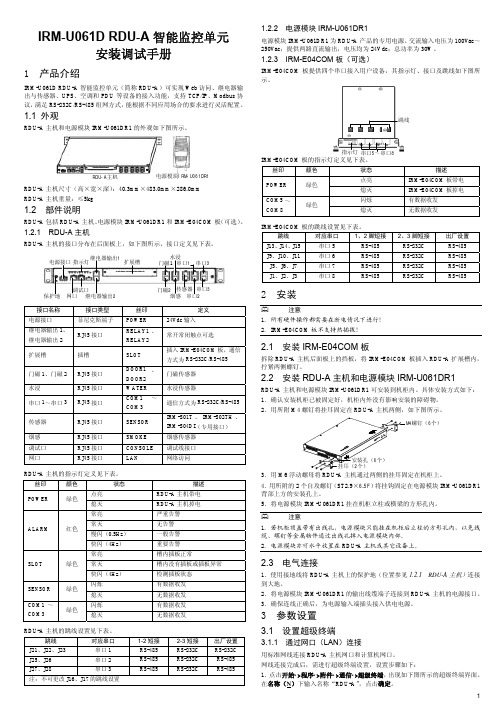
RJ45 接口 RJ45 接口 RJ45 接口
传感器
烟感 调试口 网口
RJ45 接口
RJ45 接口 RJ45 接口 RJ45 接口
门磁2 传感器 串口3 烟感 串口2
丝印 POWER RELAY1 、 RELAY2
SLOT
DOOR1 、 DOOR2 WATER COM1 ~ COM3
SENSOR
SMOKE CONSOLE LAN
RDU-A 主机和电源模块 IRM-U061DR1 可安装到机柜内。具体安装方式如下: 1.确认安装机柜已被固定好,机柜内外没有影响安装的障碍物。 2.用所附 M4 螺钉将挂耳固定在 RDU-A 主机两侧,如下图所示。
M4螺钉(6个)
安装孔(6个) 挂耳(2个) 3.用 M6 浮动螺母将 RDU-A 主机通过两侧的挂耳固定在机柜上。 4.用所附的 2 个自攻螺钉(ST2.9×6.5F)将挂钩固定在电源模块 IRM-U061DR1 背部上方的安装孔上。 5.将电源模块 IRM-U061DR1 挂在机柜立柱或横梁的方形孔内。
2.在连接时使用(N)选项中,选择计算机与 RDU-A 连接所用的串口对应的串 口号(如下图中的“COM1”),点击确定。
3.3.3 设置 RDU-A 的时间
Settime 命令用来设置 RDU-A 的时间。 在命令提示符 RDU_admin#下,输入“settime”,按 Enter 键,根据提示输入“年 -月-日:时-分-秒”,按 Enter 键使设置生效,如下图所示。
注意 1.所有硬件操作都需要在断电情况下进行! 2.IRM-E04COM 板不支持热插拔!
2.1 安装 IRM-E04COM 板
拆除 RDU-A 主机后面板上的挡板,将 IRM-E04COM 板插入 RDU-A 扩展槽内, 拧紧两侧螺钉。
3.RDU-A易睿系统软件系统介绍

点击未确认按钮,进行告警确认
已被确认的告警将不再参与告警联动逻辑; 告警确认后,不再重复发送邮件和短信通知;
实时告警确认信息仅可以在当前告警列表中显示,显示方法为鼠标移 至 已确认 文字上时自动显示;
历史告警记录中可以查询告警确认的相关信息,包括:确认人和确认 时间。
控制告警界面:控制 RDU-A和4DI/4DIF的继电器口,搜索4DI/4DIF 模块,清除通讯失败。
开关量检测:设置信号界面
设置信号界面:设置告警的判断依据,屏蔽时间等。
开关量检测:告警信号界面
告警信号界面:设置告警的级别,一般不建议修改。
调试开关量和温湿度注意事项
1.请切记点击控制界面的搜索
第三方设备驱动安装:
若在设备类型中无设备的驱动,请向400呼叫中心索取驱动安装包, 第三方设备驱动需要额外签订合同。
如何调试智能设备-SNMP设备调试:
添加驱动过程如485设备所示,不同之处为:
1.SNMP卡直接进入交换机,不需要和RDU-A有连线,但保证SNMP 卡和RDU-A之间的网络互通 2.通信参数输入的是SNMP卡的IP地址
3.网络设备和RDU-A没有直接的连线,通过交换机来进行数据传输 4.网络设备添加RDU-A的访问权限
如何添加安全站点
1.建议将RDU-A的IP设置为安全站点IP
2.使用IE6.0以及以上版本的 浏览器
告警功能设置——短信以及邮件设置:
如果用户需要短信以及邮件告警方式,需要在系统设置->人员管理 设 定好接受人的手机号码以及邮箱,然后在设置短信和邮件服务器配置
德威尔智能实验室设备有限公司产品介绍说明书
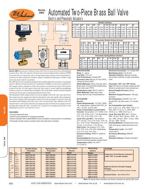
VISIT OUR WEBSITES: • • .auElectric and Pneumatic ActuatorsSeries ABV incorporates a full port brass ball valve for great flow rates with minimal pressure drop. The valve features a blowout proof stem for added safety, reinforced PTFE seats and seals for longer life, and a chrome/nickel plated ball for better performance.Actuators are direct mounted creating a compact assembly for tight spaces. Double o-ring stem seals assure leak free operation.The ABV Series is an economical automated valve package with either an electric or pneumatic actuator. Electric actuated models are weatherproof, NEMA 4, powered by standard 115VAC supply, and are available in either two-position or proportional control. Two-position actuators use the 115 VAC input to drive the valve open or closed, while the modulating actuator accepts a 4 to 20 mA input for infinite valve positioning. Actuator features thermal overload protection and a permanently lubricated gear train.The pneumatic double acting actuator uses an air supply to drive the valve open and closed.The actuator has two supply ports with one driving the valve open and the other driving the valve closed. Spring return pneumatic actuator uses the air supply to open the valve and internally loaded springs return the valve to the closed position. Also available is the SV3solenoid valve to electrically switch the air supply pressure between the air supply ports for opening and closing the valve. Actuators are constructed of anodized and epoxy coated aluminum for years of corrosion free service.FEATURES• Full port brass ball valve• Direct mount actuators for compact assembly• Electric actuator that is rated NEMA 4 and is available in two position or modulating • Pneumatic double acting or spring return rack and pinion actuatorCBA DEFSPECIFICATION Body:2 – piece.Line Size:1/4˝ to 4˝.End Connections:Female NPT.Pressure Limit:600 psi (41 bar) WOG,100 psi (6.9 bar) SWP .Wetted Materials:Body, end cap, stem:Brass; Ball: Chrome/nickel plated brass;Seat, stem seal: PTFE.Temperature Limit:300°F (148°C).Other Materials:Body seal, body O-ring, stem O-ring: Fluoroelastomer. ACTUATORS ElectricPower Requirements:115 VAC, 50/60HZ, single phase. Optional 220 VAC, 24VAC, 12 VDC, and 24 VDC.Power Consumption (Locked Rotor Current):Two position: U11: 0.55A; U12,U13, U14: 0.75A; U15: 1.1A; Modulating:V12, V13, V14: 0.75A; V15: 1.1A. Cycle Time (per 90°):Two position: U11: 2.5 sec.; U12, U13: 5 sec.; U14: 10sec.; U15: 15 sec. Modulating: V12, V13:10 sec.; V13: 20 sec.; V15: 30 sec.Duty Cycle:Two position: U11: 75%;U12, U13, U14, U15: 25%. Modulating:V12, V13, V14, V15: 75%.Enclosure Rating:NEMA 4. Optional NEMA 7.Housing Material:Aluminum withthermal bonding polyester powder finish.Temperature Limit:0 to 150°F (-17 to 65°C).Electrical Connection:1/2˝ female NPT.Modulating Input:4 to 20 mA.Standard Features:Manual override and position indicator except modulating units.Pneumatic “DA” and “SR” SeriesType:DA Series is double acting and SR Series is spring return (rack and pinion).Normal Supply Pressure:80 psi (5.5 bar).Maximum Supply Pressure:130 psig (9.0 bar).Air Connections:DA/SR1 to 5: 1/8˝female NPT, all other sizes: 1/4˝ female NPT.Air Consumption (per stroke):DA1: 2.32 cu. in.; DA2, SR2: 9.34 cu. in.;DA3, SR3: 17.21 cu. in.; DA5, SR5:39.54 cu. in.; SR6: 54.37 cu. in.Cycle Time (per 90°):DA1: .03 sec.;DA2: .05 sec.; DA3: .06 sec.; DA5: .18sec.; SR2: .09 sec.; SR3: .13 sec.; SR5:.28 sec.; SR6: .39 sec.Housing Material:Anodized aluminum body and epoxy coated aluminum end caps.Temperature Limit:-4 to 180°F (-20 to 85°C).Accessory Mounting:NAMUR standard.Standard Features: Position indicator.E CBADNote: All spring return actuators are factory standard as spring (fail) close.。
高德威产品手册(解决方案)81p

2.6.3“GA36.1-2001”车牌识别方案1.6.1.1 主要特性●功耗:采用视频图像处理器,可独立运行,通过网口和串口与车道机通讯。
抓拍单元车检器1.6.1.6.3 设备清单1.6.2标清板卡处理单元车牌识别方案1. 通信:嵌入式板卡作为一个2. 触发:车辆检测器输出存在式、进入脉冲式3. 电源:AC220V。
1.6.2.4 技术参数●抓拍图像及号牌识别时间:●号牌定位率:●通信协议:的难题。
板卡插入车道机中传输视频,视频线SYV-75-3处理单元车辆检测器信号控制,控制线RVVP2×0.5接供电,电源1.6.3标清独立处理单元1.6.3.2 订货型号GW-PR-9902T- VPDLED1.6.3.3 硬件接口1. 通信:LAN2. 触发:车辆检测器输出存在式、进入脉冲式●平均无故障连续运行时间:1.6.3.6 应用举例抓拍单元车检器控制线LED灯4 智能LED1.6.4.2 订货型号GW-PR-9902T- BKLED1.6.4.3 硬件接口1. 通信:嵌入式板卡作为一个2. 触发:车辆检测器输出存在式、进入脉冲式3. 电源:AC220V。
1.6.4.4 技术参数1.6.4.5 应用场合1.6.4.6.2 系统框图LED灯控制线ZRVVP2采集单元处理单元车辆检测器单芯屏蔽线,利用单芯导线与屏蔽线接接车检器开关量信号,触发线独立工作的处理单元,独立处理图像采集与处理,通过以太网或串口接口方式与计算机通讯,独立性强,系统性能稳定可靠。
全景抓拍单元提供动态全景图像用于辨认车型。
●号牌定位率:高速公路多路径识别拆分帐系统1.6.5.6.2 系统框图网线1.6.6标清板卡处理单元双摄像头车牌识别方案1. 通信:嵌入式板卡作为一个2. 触发:车辆检测器输出存在式、进入脉冲式3. 视频:V out,BNC;4. 电源:AC220V。
1.6.6.4 技术参数●抓拍图像及号牌识别时间:●设备接口:正实现了全天候图像清晰。
Arctis Nova 1 产品信息指南说明书

ARCTIS NOVA 1 PRODUCT INFORMATION GUIDETABLE OF CONTENTSGeneral . . . . . . . . . . . . . . . . . . . . . . . . . . . . . . . . . . . . . . . . . . . . . . . . . . 3 Product Overview . . . . . . . . . . . . . . . . . . . . . . . . . . . . . . . . . . . . . . . . . 4 Setup . . . . . . . . . . . . . . . . . . . . . . . . . . . . . . . . . . . . . . . . . . . . . . . . . . . 5 Microphone . . . . . . . . . . . . . . . . . . . . . . . . . . . . . . . . . . . . . . . . . . . . . . 6 Perfect Fit . . . . . . . . . . . . . . . . . . . . . . . . . . . . . . . . . . . . . . . . . . . . . . . 7 Regulatory . . . . . . . . . . . . . . . . . . . . . . . . . . . . . . . . . . . . . . . . . . . . . . . 8GENERALPACKAGE CONTENTSArctis Nova 1 HeadsetMain Headset CableDual 3 .5 mm Extension CableSYSTEM COMPATIBILITYPCXboxPlayStation 5PlayStation 4Nintendo SwitchSOFTWAREUse Engine inside SteelSeries GG to set customequalizer settings and control your mic .GG also has other amazing apps like Sonar, a breakthroughin gaming sound, that allows you to hear what mattersmost, through cutting-edge audio tools .DOWNLOAD NOWsteelseri.es/gg34PRODUCT OVERVIEWHEADSET1Elastic Headband 2Airweave Ear Cushions*3Retractable ClearCast Microphone 4Volume Wheel 5Microphone Mute Button 6 3 .5 mm Audio JackACCESSORIES*7Main Audio Cable 8 Dual 3 .5 mm Extension Cable*Find accessories and replacement parts at steelseries .com/gaming-accessoriesSETUPSINGLE 3.5 MM CONNECTIONSDUAL 3.5 MM CONNECTIONS56MICROPHONERETRACTABLE MICROPHONEOut of the box, the Retractable ClearCast Microphone (3) is retracted . To use the microphone, slide it away from the headset until it reaches full extension .POSITIONINGPosition the Retractable ClearCast Microphone (3) close to the corner of your mouth with the front surface facing you . Note:The microphone should not be used when retracted .PERFECT FITThere are two ways to adjust the fit of your headset1 Slide the Earcups up or down to change the overall height .2 Change the position of the Elastic Headband (1) on one or bothsides to achieve the desired tension and flex .7REGULATORYEurope – EU Declaration of ConformityHereby, SteelSeries ApS. declares that the equipment which is compliance with directive RoHS2.0 (2015/863/EU), EMC Directive (2014/30/EU), and LVD (2014/35/EU) which are issuedby the Commission of the European Community.The full text of the EU declaration of conformity is available at the following internet address: https:///SteelSeries ApS. hereby confirms, to date, based on the feedback from our suppliers indicates that our products shipping to the EU territory comply with REACH (Registration, Evaluation, Authorization, and Restriction of Chemicals - (EC) 1907/2006) compliance program. We are fully committed to offering REACH compliance on the products and posting accurate REACH compliance status for the all of products.UK Declaration of ConformityHereby, SteelSeries ApS. declares that the following equipment which is compliance with Electromagnetic Compatibility Regulations 2016, Electrical Equipment (Safety) Regulations 2016, Radio Equipment Regulations 2017 and The Restriction of the Use of Certain Hazardous Substances in Electrical and Electronic Equipment Regulations 2012 issued by the Department for Business, Energy& Industrial Strategy.The full text of the UK declaration of conformity is available at the following internet address: WEEEThis product must not be disposed of with your other household waste or treat them in compliance with the local regulations or contact your local city office, your household waste disposal service or the shop where you purchased the product.Federal Communication Commission Interference StatementThis device complies with Part 15 of the FCC Rules. Operation is subject to the following two conditions:This device may not cause harmful interference, andthis device must accept any interference received, including interference that may cause undesired operation.This equipment has been tested and found to comply with the limits for a Class B digital device, pursuant to Part 15 of the FCC Rules. These limits are designed to provide reasonable 8protection against harmful interference in a residential installation. This equipment generates, uses and can radiate radio frequency energy and, if not installed and used in accordance withthe instructions, may cause harmful interference to radio communications. However, there isno guarantee that interference will not occur in a particular installation. If this equipment does cause harmful interference to radio or television reception, which can be determined by turningthe equipment off and on, the user is encouraged to try to correct the interference by one ofthe following measures:Reorient or relocate the receiving antenna.Increase the separation between the equipment and receiver.Connect the equipment into an outlet on a circuit different from that to which the receiveris connected.Consult the dealer or an experienced radio/TV technician for help.FCC Caution:Any changes or modifications not expressly approved by the party responsible for compliance could void the user’s authority to operate this equipment.This transmitter must not be co-located or operating in conjunction with any other antennaor transmitter.Industry Canada StatementThis device complies with Industry Canada license-exempt RSS standard(s). Operation is subjectto the following two conditions:this device may not cause interference, andthis device must accept any interference, including interference that may cause undesired operation of the device.Le présent appareil est conforme aux CNR d’Industrie Canadaapplicables aux appareils radio exempts de licence. L’exploitation est autorisée aux deux conditions suivantes:l’appareil ne doit pas produire de brouillage, etl’utilisateur de l’appareil doit accepter tout brouillage radioélectrique subi, même si le brouillageest susceptible d’en compromettre le fonctionnement.This Class B digital apparatus complies with Canadian ICES-003.Cet appareil numérique de la classe B est conforme à la norme NMB-003 du Canada.该电子电气产品含有某些有害物质,在环保使用期限内可以放心使用,超过环保使用期限之后则应该进入回收循环系统。
易睿智能机柜系统RDU-A监控模块应用

什么是RDU-A
即插即用
– 支持本公司智能传感器模块的即插即用; – 支持本公司设备接入(UPS、Cooling、PDU);
配置简单
– 支持设备的动态添加、删除和修改; – 批量配置分发
现场扩展
– 支持RS232和RS485接口接入 – 支持485协议的直接接入, 也支持SNMP协议,通过交换设备接入; – 可以扩展支持第三方设备,(通过232DB9 转 RJ45,协议/线序, 走SNMP卡,需要MIB库) – 端口扩展IRM-E04COM板(选配件)
设置RDU-A的IP地址 :setip 设置RDU-A的时间:settime
注意:为保证安全,用户必须 更改缺省密码
重新启动RDU-A系统:rebootLeabharlann 通过WEB登录RDU-A界面
启动IE,在地址栏中输入RDU-A的IP地址出现登录页面 ;默认用户名 :admin,默认密码:emerson ;
注意:为保证安全,用户必须 更改缺省密码
通过超级终端登录RDU-A界面
通过网口(LAN)登录:设置步骤(缺省IP:192.168.0.254)
通过超级终端登录RDU-A界面
通过调试口(CONSOLE)登录:设置(115200,n,8,1)
DB9母座 RJ45端口
连接电缆说明
RJ45端口与DB9母座接线
功能 CTS CD Rx SG SG Tx DTR DSR
跳线J21~J23、J25~J28
跳线 J21,J22,J23
J25,J26 J27,J28
1、2脚短接 RS-485 RS-485 RS-485
跳线J21~J23、J25~J28放大图
2、3脚短接 RS-232C RS-232C RS-232C
DA D V 版 使用手册

安全警告
小心
● 接线必须正确而且牢固,否则可能会使伺服电机错误运转,也可能因接触不良损坏设备。 ● 伺服电机 U、V、W|端子不可反接,不可接交流电源。 ● 伺服电机与伺服驱动单元之间须直连,不能接入电容、电感或滤波器。 ● 防止导电紧固件及电线头进入伺服驱动单元。 ● 电线及不耐温体不可贴近伺服驱动单元散热器和伺服电机。 ● 并接在输出信号直流继电器上的续流二极管不可接反。
本产品异常意外事故。
验收
● 损坏或有故障的产品不可投入使用。
小心
运输
小心
● 必须按产品储运环境条件储存和运输。 ● 不得超高堆放,防止跌落。 ● 转运时产品应包装妥善。 ● 不得拖拽电线、电机轴和编码器搬运伺服电机。 ● 伺服驱动单元及伺服电机不得承受外力及撞击。
安装
小心
伺服驱动单元和伺服电机: ● 不得安装在易燃品上面或附近,防止火灾。 ● 避免振动,严禁承受冲击。 ● 受损或零件不全时,不得进行安装。 伺服驱动单元: ● 必须安装在足够防护等级的控制柜内。 ● 必须与其它设备间保留足够的间隙。 ● 必须有良好的散热条件。 ● 防止尘、腐蚀性气体、导电物体、液体及易燃易爆物质侵入。 伺服电机: ● 安装务必牢固,防止因振动松脱。 ● 防止液体侵入损坏电机和编码器。 ● 禁止敲击电机和电机轴,以免损坏编码器。 ● 电机轴不可承受超越极限的负荷。
第六章 显示与操作 .......................................................36 6.1 键盘操作 ..........................................................36 6.2 监视方式 ..........................................................36 6.3 参数设置 ..........................................................39 6.4 参数管理 ..........................................................39 6.5 速度试运行.........................................................41 6.6 JOG运行 ...........................................................41 6.7 其它 ..............................................................41
艾默生易睿RDU监控系统功能与分布式机房组网方案的介绍

RDU易睿监控系统架构简介
Card
议程2
1 RDU易睿监控方案介绍
2
RDU-A监控单元介绍
3 RDU-M机房管理器介绍
4 RDU监控方案配置介绍
5 经典案例分享 6 RDU-A/M系统演示
RDU-A监控系统硬件组成
RDU-A 设备接入能力介绍
1.通过485串口方式组网最 多可连接6台; 2.通过SNMP卡IP组网理论 上无限制,考虑系统数据传 输速度,建议连接10台内
数量 4 1 3 3 1 1 8 1 8 4 1 1
RDU易睿监控适用场景3 –中型数据中心
设备
机柜 PEX空调 UPS 60KVA UPS电池柜 SPM RDU监控单元 PDU KVM/TFT 温湿度传感器 门碰 烟感 漏水
数量
20 2 2 2 1 2 40 1 40 20-40 1 1-5
RDU易睿监控适用场景4 –分布式数据机房
-使用价值:
为满足业务需求,在4.1期微模块的基础上启动4.2期建设。将目前余
-用户介绍
下的9个微模块场地建设为高压直流微模块,采用一路市电加一路高
腾讯公司成立于1998年11月,是目 前中国最大的互联网综合服务提供 商之一,也是中国服务用户最多的
压直流同时供电方案;
-主要配置简介:
型号描述 SPM-120
4
Emerson Confidential
哪里可以用到易睿RDU监控系统?
网络接入间
应用场景
主要特征
1 网络接入间
1.5~3KW,无专用机房
2 计算机房
10-25KW,面积小于60平方米
3 中型数据中心 25-100KW,面积小于200平方米
PEX空调接入RDU-A调试指导手册
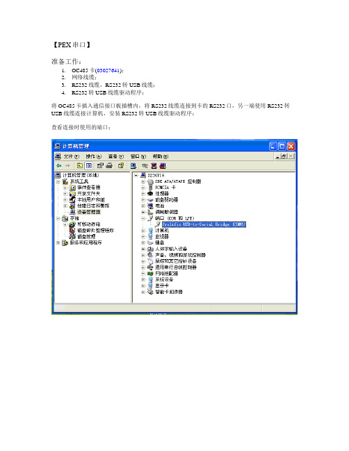
【PEX串口】准备工作:1.OC485卡(03027641);2.网络线缆;3.RS232线缆,RS232转USB线缆;4.RS232转USB线缆驱动程序;将OC485卡插入通信接口板插槽内,将RS232线缆连接到卡的RS232口,另一端使用RS232转USB线缆连接计算机,安装RS232转USB线缆驱动程序;查看连接时使用的端口;开始→程序→附件→通讯→超级终端输入“PEX[COM]“;连接时使用“COM6”COM6属性页,通讯参数“9600,N,8,1“,数据流控制”无“,点击”确定“;主菜单选择“1“;用户可自定义修改OC485卡参数;测试连通性;输入”X”,保存修改参数;登陆RDU-A,默认用户名:admin,密码:emerson;未添加前,RDU-A的WEB管理界面;“配置管理”→”设备管理”→”添加/修改/删除设备”,输入对应参数,点击添加设备;添加成功后,点击“保存配置”;输入登陆密码,默认“emerson”;重启过程中;已添加;数据采集正常,测试成功;【PEX空调网络方式】准备工作:1.TCP/IP卡(03027640);2.网络线缆;3.RS232线缆,RS232转USB线缆;4.RS232转USB线缆驱动程序;将TCP/IP卡插入通信接口板插槽内,将RS232线缆连接到卡的RS232口,另一端使用RS232转USB线缆连接计算机,安装RS232转USB线缆驱动程序;查看端口;“开始“→“附件”→“通讯”→“超级终端”;输入“PEX”;连接时使用选择“COM6”;COM6属性页面,通讯参数“9600,N,8,1”,数据流控制“无”,然后点击“确定”按钮;输入“1”;修改IP;修改网关设置;按2次”ESC”,输入5,测试连通性;输入X,保存配置;测试;输入TCP/IP设置的IP,回车;点击主菜单Configure,输入用户名,密码,默认“用户名:Liebert,密码:Liebert”点击Access,选择edit按钮,输入RDU-A的IP;点击Traps,输入RDU-A的IP,点击“Save”;登陆RDU-A;RDU-A主页面;选择“添加/修改/删除设备”,点击“添加设备”按钮,按要求输入参数;点击“保存设置”在出现的对话框中输入登陆密码,默认”emerson”;重启中;查看PEX的SNMP网络接入;测试成功;。
冷媒分配单元(RDU)安装手册pdf
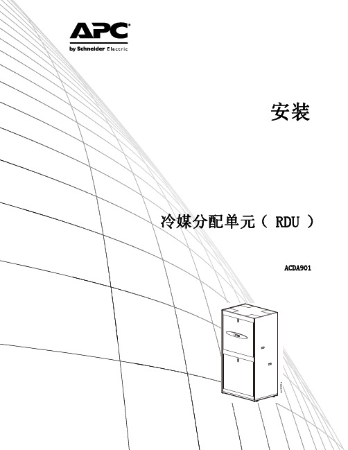
冷媒分配单元 (RDU)
ACDA901
na3100a
This manual is available in English on the enclosed CD. Dieses Handbuch ist in Deutsch auf der beiliegenden CD-ROM verfügbar. Deze handleiding staat in het Nederlands op de bijgevoegde cd. Este manual está disponible en español en el CD-ROM adjunto. Ce manuel est disponible en français sur le CD-ROM ci-inclus. Questo manuale è disponibile in italiano nel CD-ROM allegato. 本マニュアルの日本語版は同梱の CD-ROM からご覧になれます。 Instrukcja Obsługi w jezyku polskim jest dostepna na CD. O manual em Português está disponível no CD-ROM em anexo. Данное руководство на русском языке имеется на прилагаемом компакт-диске. 您可以从包含的 CD 上获得本手册的中文版本。 您可以从付属的CD上获得本手册的中文版本。
目录
一般信息.......................................... 1
请妥善保存这些说明 目标用户 手册更新 操作环境 . . . . . . . . . . . . . . . . . . . . . 1 . . . . . . . . . . . . . . . . . . . . . . . . . . 1 . . . . . . . . . . . . . . . . . . . . . . . . . . 1 . . . . . . . . . . . . . . . . . . . . . . . . . . 1 . . . . . . . . . . . . . . . . 1 . . . . . . . . . . . . . . . . . 1 . . . . . . . . . . . . . . . . 1
最新01-青铜器RDM用户操作手册-系统安装分册V1.0
01-青铜器R D M用户操作手册-系统安装分册V1.0青铜器RDM用户操作手册系统安装分册特别声明为了保护您的合法权益,青铜器RDM采用硬件+软件的整体加密模式,详细情况请与青铜器软件联系,联系方式请参考封底。
青铜器RDM系统版权归青铜器软件所有。
“青铜器软件”、“Power YourR&D”、“Bronzesoft”均为青铜器软件注册商标,未经青铜器软件书面授权许可,不得擅自使用。
本资料仅为提供信息而用,青铜器软件并不因本资料而做出任何明示的或隐含的保证。
本资料包含的信息会随青铜器RDM研发管理系统的发展而做出相应的改变,本资料不作为青铜器软件的任何承诺,产品信息以按照销售协议连同许可证一起实际交付的青铜器RDM软件系统为准。
本操作手册仅供参考,系统使用功能最终以青铜器RDM软件系统为准。
目录1产品概述 (5)2数据库安装 (6)2.1M ICROSOFT SQL S ERVER安装指南 (6)2.1.1Microsoft SQL Server 安装前注意事项 (6)2.1.2Microsoft SQL Server 安装步骤 (6)2.1.3Microsoft SQL Server 安装后注意事项 (23)2.1.4Microsoft SQL Server 创建数据库方法 (24)2.2M Y SQL安装指南 (26)2.2.1My SQL 安装前注意事项 (26)2.2.2My SQL 安装步骤 (26)2.2.3My SQL 安装后注意事项 (36)2.2.4My SQL 创建数据库方法 (37)3RDM安装 (40)3.1安装RDM步骤 (40)3.2卸载RDM步骤 (48)4高级配置 (49)4.1TOMCAT端口配置 (49)4.2局域网中使用域名访问的配置 (49)4.2.1环境要求 (49)4.2.2注意事项 (49)4.2.3域名配置步骤 (49)5安装后生成目录介绍 (51)5.1日志文件目录 (51)6常见问题与分析 (52)6.1重复安装数据库出现告警问题 (52)6.2成功创建SQL S ERVER数据库后,RDM系统不能连接上该数据库 (52)6.3成功创建M Y SQL数据库后,RDM系统不能连接上该数据库 (52)6.4成功创建M Y SQL数据库和安装RDM后,登录RDM出现中文字符乱码 (52)6.5成功安装RDM系统后,启动RDM服务时,服务器没有反应 (52)6.6服务器端口冲突问题 (53)6.7连接数据库名称错误 (53)6.8RDM服务启动成功,但只有服务器本机可登录系统,其他客户端无法连接 (54)1 产品概述本软件系统是一个基于研发项目管理、研发多项目组合管理、研发资源管理、研发绩效管理、缺陷管理、技术评审管理、文档管理、问题管理、风险管理、产品数据管理(物料、BOM、图档、基线、供应商)、产品结构管理、产品规划管理的平台。
ACV用户手册(修订版1)
目录敬告 ............................................ 错误!未定义书签。
1. 安全注意事项.................................... 错误!未定义书签。
1.1说明....................................... 错误!未定义书签。
1.2安全注意事项............................... 错误!未定义书签。
2、产品概述 ....................................... 错误!未定义书签。
2.1 简介 ...................................... 错误!未定义书签。
2.2 工作原理................................... 错误!未定义书签。
2.3 电荷感应技术测量煤粉流速的原理............. 错误!未定义书签。
2.4 电荷感应技术测量煤粉浓度的原理及ACV-2000系统的功能特点错误!未定义书签。
3 、主要组成部分................................... 错误!未定义书签。
3.1 传感器 .................................... 错误!未定义书签。
3.2 信号采集处理单元........................... 错误!未定义书签。
4、系统技术性能指标................................ 错误!未定义书签。
5、安装及注意事项.................................. 错误!未定义书签。
5.1 系统整体安装简介........................... 错误!未定义书签。
5.2 传感器底座开孔及安装....................... 错误!未定义书签。
阿尔法拉瓦尔UltraPure单点载量传感器的商品说明说明书

process weighing installation where level measurement,mixing,filling, dosing or batching is required.The weighing solution is as standard delivered in two different accuracy ranges:0.025%and0.015%with a total measuring range from0to150kg.Each weighing system consists of a digital single point load cell anda weighing module.The weighing modules are available with both analog4-20mA output,and fieldbus interface(PROFINET,Profibus DP or EtherNet IP).For high hygienic demands,the Alfa Laval load cells are supplied electropolished and hermetically sealed to IP68(laser welded).Capacitive measurement principle(patented)The Alfa Laval robust digital load cells are based on a patented capacitive measurement principle where a non-contacting capacitive sensor is mounted inside the load cell body.As the capacitive sensor is not in contact with the load cell body,the load cells are to a very high degree unaffected by overloads,sideloads,torsion and welding voltages.Therefore,a straightforward and hygienic mechanical installation of the load cells can be done without expensive and complicated mounting kits and overload protection devices.The electrical installation of the digital load cells is pure plug-and-play as the signal from the non-contacting capacitive sensor is directly converted,compensated and calibrated by a patented ASIC.The digital signal is transmitted as RS485data on a reliable RG-58single wire coaxial cable which may be up to50meters long.The factory calibration of the digital load cells is independent of the load cell cable length.Technical dataMeasuring range:..............from0to150kg dependingon system selection. Accuracy:...................0.025%,0.015% Compensated temperature range:...-10to50°COverload and sideload:..........300%overload tolerance Power supply:................24VDC±10%,min.2A Mechanical dataWeight:Load cell:Type TE67WS................SPSX2.5kgWeighing modules:.............approx.0.5kgMaterials:Load cells:..................AISI316and17-4PH Operating temperature range:Load cells:..................-50to70°C(100°C withteflon cable)Weighing modules:.............-10to50°CProtection class:Load cells:..................IP68Weighing modules:.............IP20CertificatesCE marked3.1B certificateCalibration certificate(Option)OptionsOutput:4-20mAPROFINETEtherNet IPProfibus DPRS485Local weighing display:Alfa Laval weighing displayLoad cell cable:6m standard coaxial RG58with BNC connector(option:10,20or 50m)Layout and electrical connection schematic of the load cells the weighing module:Weighing module with display Weighing module without displaySpecificationParameter Unit0.025%0.015% Rated capacity(Emax)per load cell kg5,10,20,50,100,150 Safe overload limit%of E max300to1000Safe sideload limit%of E max500to2000 Minimum dead load%of E max0 Accuracy%of E max0.0250.015 Repeatability%of E max0.0080.005 Hysteresis%of E max0.0100.005 Creep30min.%of E max0.0150.010 Temperature effect on zero%/10°C0.0300.020 Temperature effect on sensitivity%/10°C0.0300.020 Deflection at Emax mm max.0.10 Mesuring rate Hz up to1000 Internal resolution Bit24Dimensional drawingsSingle point load cell,type SPSXDisplayA-A (1:1)Stainless steelboxA-A4500-0035Selection guideWhen configuring a weighing system,you need the following information:•Total weight of vessel incl.product in kg•Required output and/or local display•Required accuracy for the application(0.025%or0.015%)With this information,yoy are able to find the configuration you need in the price list or in the online configuration tool: Step1:Calculate the total weight of the tank inclusive the product in kg and round up to the nearest standard load cell system. Step2:Decide on accuracy required by the application-0.025%accuracy systems are suitable for dosing applications-0.015%accuracy systems are suitable for very precise dosing and batching applicationsStep3:Decide on the output signal type and/or a local weighing display:-4-20mA-PROFINET-EtherNet IP-Profibus DP-RS485Step4:Decide if you want the display and/or weighing modules supplied mounted in a stainless steel boxYou have the following options:-Without stainless steel box-Weighing module mounted in stainless steel box(without display)-Display mounted in stainless steel boxStep5:Decide on the length of the load cell cables(the length of the cable is can be shortened without the need for recalibration) -6m(standard)-10m-20m-50mStep6:Decide on if you need Calibration certificateAlfa Laval reserves the right to change specifications without prior notification.How to contact Alfa LavalContact details for all countriesare continually updated on our website.Please visit toaccess the information direct.A l f a L a v a l i s a t r a d e m a r k r e g i s t e r e d a n d o w n e d b y A l f a L a v a l C o r p o r a t e AB . E S E 03346e n 1802。
艾默生RDU-A介绍

产品功能
●即插即用
–支持本公司智能传感器模块的即插即用;
–支持本公司设备接入(UPS、Cooling、PDU);
●配置简单
–支持设备的动态添加、删除和修改;
–批量配置分发
●现场扩展
–支持RS232和RS485接口接入
–可以扩展支持SNMP协议接入智能设备;
–可以扩展支持第三方设备接入(需定制)
–端口扩展IRM-E04COM板(选配件)
●告警通知
–提供告警实时通知功能,无人值守
–定时提醒用户
–电话、短消息(GSM/CDMA)、邮件
●高级功能
–任意告警映射(通过简单的可编程逻辑控制功能)
–新设备类型接入
–软件远程升级
硬件架构。
RD7000PlusMRXUGCNV1说明书
中文28E N G L I S PrefaceAbout this guideCAUTION: This guide provides basic operating instructions for the RD7000+ locator and transmitter. It also contains important safety information and guidelines and as such should be read in its entirety before attempting to operate the RD7000+ Locator and transmitter.This guide is intended as a quick reference guide only. For detailed instructions, includingthe use of accessories, help with eCert ™, CALSafe ™*, SurveyCERT ™ and automatic logging* please refer to the RD7000+ locator operation, SurveyCERT and RD Manager ™ manuals, which are available for download from . The online User Manual library also contains links to the SurveyCERT and RD Manager manuals.*Logging models only.E N G L I RD7000+ locatorLocator features1. Keypad2. LCD with auto backlight3. Speaker4. Battery compartment5. Battery charger connector6. Accessory connector7. Headphone connector8. Bluetooth ® module antenna 9. Marker loop antennaLocator keypad10. Power key : Switches the unit onand off. Opens the locator menu.11. Frequency key : Selects frequency.Closes submenu.12.13. null and null (PLM and TLM models) modes. With antenna folded down, toggles marker and combined (marker/line) modes. Opens a submenu.14. Graph key : Saves SurveyCERTmeasurements.15. Transmitter key : Not used.Locator screen icons16. Indicates the signal strength and peak marker.17. Signal strength: Numerical indicationof signal strength.18. Peak / Proportional arrows: Indicatesthe location of the line relative to the locator.19. Battery icon: Indicates the battery level.20. Volume icon: Displays the volume level.21. Fault-Find arrows (PLM and TLMmodels only).22. Radio Mode: Indicates when RadioMode is active.23. Power Mode: Indicates when PowerMode is active.24. Accessory or Measurement indicators:Indicate when an accessory is connected or if measurements are active 25. A-Frame icon: Indicates when theA-Frame is connected.26. Operating mode indicator.27. Bluetooth icon: Indicates status ofBluetooth connection. Flashing icon means pairing is in progress. Solid icon indicates an established connection is active.28. Antenna mode icon: Indicates antennaselection: Peak, Null and combined Peak/Null.29. Sonde icon: Indicates that sonde signalsource is selected (DLM, PLM and TLM models).30. Line icon: Indicates that line signalsource is selected.31. Compass/Marker mode indicator:Shows the direction of the located cable relative to the locator. Also used as a graphical indication for Marker mode active32. Current /depth indicator.567932481161718182130321920222324252627283129E Tx-1, Tx-5 and Tx-10 transmitters132Transmitter features 1. Keypad.2. LCD.3. Removable accessory tray.4. D-cell battery tray.5. Rechargeable battery pack(Optional).Transmitter keypad6.Power key : Switches the unit onand off. Opens the transmitter menu.7. Frequency key : Selects frequency.Menu navigation key.8. menu options.9. Measure key : Opens a sub menu.Used to take voltage and impedance measurements.Transmitter screen icons10. Battery icon: Indicates the battery level.11. Alphanumeric description of selectedoperation mode.12. Standby icon: Appears when thetransmitter is in Standby mode.13. Output level: Displays transmitteroutput power.14. Clamp icon: Indicates when a clamp orother plug is connected.15. DC icon: Appears when the transmitteris powered from a DC source.16. Induction indicator: Appears when thetransmitter is in Induction mode.17. A-Frame (Tx-5 and Tx-10 only):Indicates when the transmitter is in Fault-Find mode.18. CD Mode indicator (Tx-10 only):Indicates that the transmitter is in Current Direction mode. For use with RD8000™ locators only.19. Voltage warning indicator: Indicatesthat the transmitter is outputting potentially hazardous voltage levels.20. Volume icon: Displays the volume level.21. Pairing icon (Tx-5B and Tx-10B only):For use with RD8000 locators only.22. Bluetooth icon (Tx-5B and Tx-10B only).For use with RD8000 locators only.54Before you beginIMPORTANT! This guide is intended to be a quick reference guide. We recommend you read the operation manual before you attempt to operate the RD7000+ locator! First useFor safety reasons RD7000+ locators are shipped with the Li-Ion battery packs disconnected and transmitters with no D cells in the battery tray.To connect the Li-Ion battery pack open the RD7000+ battery compartment and plug the battery lead into the battery connector.To fit the D cell batteries in the transmitter, unlatch the accessory tray. The battery compartment is located underneath the transmitter body. Use the turnkey to unlatchthe battery compartment. Insert eight D-Cell Alkaline or NiMH batteries.System setupIt is important that you set up the system according to your personal preferences and operating requirements before you conduct your first survey. Y ou can set the system up using the RD7000+ menu as described below.NOTE: These procedures refer to both the transmitter and locator unless stated otherwise.Before changing settings, switch the locator or transmitter on by pressing the key. NOTE: Once the system is switched on, pressing the key momentarily will activate the locator or transmitter menu.Using the menusThe RD7000+ locator and transmitter menus allow you to select or change system options. Once entered, the menu is navigated using the arrow keys. Navigation is consistent on both the transmitter and the locator. When in the menu, most on-screen icons will temporarily disappear and the menu options will appear in the bottom left-hand corner of the display. Note that when browsing the locator menu, the andWhen browsing the transmitter menu the and keys act as left and right arrows. The right arrow enters a submenu and the left arrow returns to the previous menu.NOTE: When you select an option and press the key, the option will be enabled automatically.Locator menu options• VOL: Adjust the speaker volume from 0 (mute) to 3 (loudest).• BT: Enable, disable, reset or pair Bluetooth connections. Also defines the protocol used when connecting to a PC or PDA.• UNITS: Select metric or imperial units.• CAL: Displays the date of original factory calibration and the most recent service calibration or eCert calibration validation.• MARKR: Enable or disable individual utility markers.• LANG: Select menus language.• POWER: Select power frequency: 50 or 60Hz.• ANT: Enable or disable any antenna mode with the exception of Peak.• FREQ: Enable or disable individual frequencies.• ALERT: Enable or disable Strike Alert™.• BATT: Set battery type: ALK, NiMH or Li-ION.• COMP: Enable or disable display of the Compass feature.To navigate the locator menu:1. Press the key to enter the menu.2.or3.4. or5. Press the key to confirm a selection and return to the previous menu.6. Press the key to return to the main operation screen.Transmitter menu options• VOL: Adjust the speaker volume from 0 (mute) to 3 (loudest).• FREQ: Enable or disable individual frequencies.• BOOST: Boost transmitter output for a specified period of time (in minutes).• LANG: Select menus language.•OPT F: Enable or disable SideStep auto™.• BATT: Set battery type: ALK, NiMH or Li-ION – Also select Eco mode for alkaline batteries only.• MAX P: Allow the transmitter to output its maximum wattage.• MODEL: Specify the model of your locator.• MAX V: Set the output voltage.• BT: Enable, disable or pair Bluetooth connections to a RD8000 locator (Bluetooth models only).To navigate the transmitter menu:1. Press thekey to enter the menu.2.or3.4.5. Press the key to return to the previous level or exit the menu.6. Press the key to return to the main operation screen.Examples of using the menu, selecting options and making changes:LanguageTo select your preferred menu language:1. Press the key to enter the menu.2.3. key (on the locator) or the key (on the transmitter) to enter the LANG menu.4. Scroll up or down to select your preferred language.5. Press the key to accept your selection and return to the main menu.6. Press the key to return to the main operation screen.Power / mains frequency (locator only)To select the correct frequency (50 or 60Hz) for your country or region’s power supply:1. Press the key to enter the menu.2.3.4. Scroll up or down to select the correct frequency.5. Press the key to accept your selection and return to the main menu.6. Press the key to return to the main operation screen.Units (locator only)The RD7000+ locator allows you to work in Metric or Imperial (US customary) units. To select your preferred units of measurements:1. Press the key to enter the menu.2.3.4. Scroll up or down to select Metric or Imperial units.5. Press the key to accept your selection and return to the main menu.6. Press the key to return to the main operation screen.BatteriesThe locator and transmitter are battery powered.The RD7000+ locators are provided with a rechargeable Lithium-ion (Li-Ion) battery pack as standard. The RD7000+ locators can also be powered using good quality D-cell alkaline or NiMH batteries.Transmitters can be powered by D-cell alkaline batteries (as standard), D-cell NiMH batteries, or by an optional accessory Li-Ion battery pack. Alternatively, you can power the transmitter from a mains or vehicle power source using a Radiodetection supplied optional accessory adapter.If using D-Cells it is important to set the system to match the currently installed battery type to ensure optimal performance and correct battery level indication.To set your battery type:1. Press the key to enter the menu.2.3. key (on the locator) or the key (on the transmitter) to enter the4. Scroll up or down to select the correct battery type.5. Press the key to accept your selection and return to the main menu.6. Press the key to return to the main operation screen.When using alkaline batteries Eco mode can be selected to maximize their usage. When Eco mode is selected the transmitter automatically reduces its max power output when the batteries cannot longer supply enough energy.Shutting downTo switch the locator or the transmitter off, press and hold the key until the screen goes blank.Locating pipes and cablesPassive FrequenciesPassive frequency detection takes advantage of signals that are already present on buried metallic conductors. The RD7000+ supports three types of passive frequencies: power, radio, CPS (DL models only). Y ou can detect these frequencies without the aid of the transmitter.Active FrequenciesActive frequencies are applied direct to the pipe or cable using the transmitter. The transmitter can apply a signal using three methods:Direct connectionIn direct connection, you connect the transmitter directly to the pipe or cable you wish to survey. The transmitter will then apply a discrete signal to the line, which you can trace using the locator. This method provides the best signal on an individual line and enables the use of lower frequencies, which can be traced for longer distances.Connecting the transmitter to a pipe or line requires the use of a direct connection lead and a ground stake to complete the circuit.WARNING! Direct connection to live conductors is POTENTIALL Y LETHAL. Direct connections to live conductors should be attempted by fully qualified personnel only using the relevant products that allow connections to energized lines.InductionThe transmitter is placed on the ground over or near the survey area. Y ou select the appropriate frequency. The transmitter will then induce the signal indiscriminately toany nearby metallic conductor. In induction mode, using higher frequencies is generally recommended as they are induced more easily onto nearby conductors.ClampThe optional signal clamp can be used to apply the transmitter signal to an insulated live wire or pipe up to 8.5"/215mm in diameter.WARNING! Do not clamp around uninsulated live conductors.WARNING! Before applying or removing the clamp around a power cable ensure that the clamp is connected to the transmitter at all times.Refer to the Signal Clamps paragraph in the Using Accessories section.Locating RF MarkersThe RD7000+ locator enables users to locate most common RF utility markers. These are also referred to as Electronic Marker System (EMS) and Omni markers.To enable marker locate mode lower the marker loop antenna. To disable the marker locate mode fold the loop antenna up.Marker typesThe RD7000+ can detect 9 different RF Markers, as shown in the table below.*Use of the red Electrical Power (PWR) marker locate mode is subject to radio licensing restrictions for Short Range Devices in the EU and possibly other countries. It is the responsibility of the userto ensure that the red Power (PWR) marker locate mode is only enabled in countries where radio licensing restrictions do not apply at the operating frequency of 169kHz.If required and permitted use RD Manager to enable this frequency.Using accessoriesThe locator and transmitter are compatible with a wide range of accessories. For detailed information on using any of the accessories below please refer to the RD7000+ locator operation manual.Signal clampsWhen it is not possible to connect directly onto a pipe or cable, or induction mode is unsuitable, a transmitter signal clamp may be used. The clamp is plugged into the output of the transmitter and provides a means of applying a locate signal to an insulated live wire. This is particularly useful with live insulated cables as it removes the need to disable the power and break the line.WARNING! Do not clamp around uninsulated live conductors.WARNING! Before applying or removing the clamp around a power cable ensure that the clamp is connected to the transmitter at all times.To locate or identify individual lines a locator signal clamp can be connected to the accessory socket of the locator and can be clamped around individual pipes or cables. StethoscopesAt times, it may not be possible to use a clamp around a cable because of congestionor inaccessibility. A stethoscope antenna should be used in place of a clamp to identify cables.Radiodetection supplies a range of stethoscopes to suit most applications.To use a stethoscope, connect it to the locator’s accessory socket. The locator will automatically detect the device and filter out location modes that are irrelevant. Sondes and FlexiTraceSondes are battery powered transmitters that are useful for tracing non-metallic pipes. The RD7000+ can detect a range of sonde frequencies, including those transmitted by Flexisondes, GatorCam™4 or flexiprobe™ pushrod systems and P350 flexitrax™ crawlers. For a detailed guide on locating sondes, please refer to the operation manual.A FlexiTrace is a traceable fiberglass rod incorporating wire conductors with a sondeat the end. It is connected to the output of the transmitter and is typically used in small diameter, non-metallic pipes. The user has the option of locating the entire length of the cable or choosing to locate only the tip of the cable.The FlexiTrace has a maximum power rating of 1W. When using the FlexiTrace with a Radiodetection Tx-5(B) or Tx-10(B) transmitter the output limit must be set to 1W in the MAX P menu and the output voltage limit set to LOW in the MAX V menu.personal injury and damage to the equipment.Fault-finding with an A-FrameThe RD7000+ PLM and TLM models have the ability to detect cable sheath faults accurately using an A-Frame accessory. The Tx-5 and Tx-10 provide a fault finding signal that can be detected by the A-Frame as a result of the signal bleeding to ground through damaged cable sheaths.For a detailed guide to fault-finding, please refer to the operation manual.Plug / L ive cable connectorThe plug connector is connected to the output of the transmitter and is used to put a signal onto a line and trace it from a domestic mains plug to the service cable in the street.The live cable connector can be used to apply a signal to a live cable. Only suitably qualified personnel should use this equipment.Submersible Double Depth AntennaThis antenna is connected to the locator and used to locate pipes and cables underwater at depths down to 100 metres.WARNING: use of the submersible antenna should be by fully licensed and experienced personnel only, and only after fully reading the operation manual! Transmitter Rechargeable battery packsRechargeable battery packs for the transmitter are available and are supplied with suitable chargers. The rechargeable battery packs provide superior performance over traditional alkaline batteries.Bluetooth wireless connectionsRD7000+ locators feature a Bluetooth wireless module, as standard, providing the ability to connect to compatible devices such as PCs, laptops or handheld devices running a compatible application.NOTE: The RD7000+ locator wireless features may be subject to national and or local regulations. Please consult your local authorities for more information.WARNING! Do not attempt any wireless connection in areas where such technology is considered hazardous. This may include: petrochemical facilities, medical facilities or around navigation equipment.Switching bluetooth onBy default RD7000+ locators and Bluetooth enabled transmitters are shipped with the Bluetooth wireless connection module disabled.1. Press the key to enter the menu.2.3. key (locator) or the key (transmitter) to enter the BT menu.4. Scroll up or down to the ON option.5. Press the key to switch Bluetooth ON and return to the previous menu. Switching bluetooth offY ou can switch Bluetooth off to prolong battery life or comply with regulations in areas where wireless communications are considered hazardous.1. Press the key to enter the menu.2.3. key (locator) or the key (transmitter) to enter the BT menu.4. Scroll up or down to the OFF option.5. Press the key to switch Bluetooth off and return to the previous menu. Pairing to a PDA or PCConnection requirements:• Any RD7000+ locator.• A compatible Bluetooth enabled PDA or Bluetooth enabled PC or Laptop.NOTE: The procedure below describes the pairing process between a RD7000+ locator and a PDA. Pairing to a PC follows the same steps for the RD7000+ locator and similar steps for your PC or laptop. Consult your PC or laptop Bluetooth pairing instructions to pair with the RD7000+ locator.Pair the RD7000+ locator to your PDA using your PDA’s Bluetooth software.NOTE: The procedure for pairing your PDA may differ depending on the PDA make and model. The following procedure should apply to most PDAs.On the locator:1. Press the key to enter the menu.2.3.4. Scroll up or down to the PAIR menu.E N G L I S 5.6. Scroll up or down to the BT-PC option.7. Press thekey and the locator will attempt to pair with your PDA.On your PDA:8. From the PDA’s Start menu , select Settings then select the Connections Tabfollowed by the Bluetooth icon.9. Ensure the Bluetooth radio is switched on and make the PDA visible to other devices.10. Select the Devices tab and scan for new partnerships.11. Create a partnership with the RD7M_xxx device.12. If asked for a passkey, enter 1234.13. Select the COM Ports tab and make a New Outgoing Port with the RD7000+locator. Note the port number of the selected COM port.TroubleshootingSuccessful wireless communication depends on a number of factors including: battery life, electromagnetic interference, device memory and physical obstructions.Ensure that the RD7000+ locator and any other wireless device is sufficiently charged for wireless communication. Note that many PDAs will suspend wireless connections when their battery capacity drops below a threshold percentage. Consult your device’s documentation for more information.Excessive electromagnetic interference can effectively limit the range of wireless communication and / or corrupt data.Y our PDA device may have insufficient memory to maintain a wireless link, particularly if the connection is sustained over an hour or longer. Make sure you quit applications on your PDA using the method described in your device’s documentation.Resetting connectionsIf you experience problems with the RD7000+ wireless Bluetooth technology features, Radiodetection recommends resetting the connection and then pairing your device again:1. Press thekey to enter the menu.2.3.4. Scroll up or down to the RESET menu.5. Press the key and the locator will purge all current connections.6.Re-pair your devices. bluetooth error codesIf an error occurs when attempting to perform any Bluetooth command using the locator to the transmitter or the locator to a PC or PDA, the LCD will display a code to help you resolve the problem on the locator.The codes are as follows:Survey MeasurementsThe RD7000+ locator models can transmit survey measurements to a paired Pocket PC (or PDA) with GPS, running a compatible application such as SurveyCERT.Saving measurementsTo save survey measurements, press thekey.To achieve accurate results the locator must be kept as still as possible during the saving process.If your PC or PDA is out of reach the locator will display an error code. To avoid these errors disable the Bluetooth survey measurements transmission or ensure that your PC or PDA is within range and correctly paired.NOTE: A flashing depth and/or current reading display means that themeasurement is poor and should be taken again. Poor readings may be caused by nearby conductors or sources of electromagnetic interference.To obtain SurveyCERT for PDA:SurveyCERT for PDAs and its operation manual are available as a free download from the Radiodetection website:1. Visit .2. Using the menu bar, go to Support -> SurveyCERT.3. Click on the RD7000+ SurveyCERT link to get to the SurveyCERT download pageand follow the instructions.CALSafeCALSafe enabled RD7000+ (PLM and TLM models only) are equipped with a system which does not permit them to function once they are beyond the expected service/ calibration date.When the unit is within 30 days of the service due date the unit will display at startup the number of days left. The locator will stop functioning on the service due date.Y ou can edit the CALSafe service due date or disable this function using the RD Manager PC software. Refer to its operation manual for further information. Automatic LoggingRD7000+ logging models (PLM and TLM) offer a powerful data logging system which records all the instrument’s critical parameters and warnings in its internal memory at the rate of 1/sec.The automatic logging system is always active and cannot be disabled. Its memory is capable of storing at least 1 year’s worth of normal usage data – based on 4 hours operation per day, 5 days per week, 20 days per month.Logs can be retrieved using the RD Manager PC application for usage analysis and survey validation. Refer to its operation manual for further information. Important noticesWhen reporting any problems to your Radiodetection Dealer or Supplier it is important to quote the unit serial number and the purchase date.This instrument, or family of instruments, will not be permanently damaged by reasonable electrostatic discharge and has been tested in accordance with IEC 801-2. However,in extreme cases temporary malfunction may occur. If this happens, switch off, wait and switch on again. If the instrument still malfunctions, disconnect the batteries for five seconds and then reinstall and switch the unit on.ComplianceEU ComplianceThis equipment complies with the following EU Directives:• R&TTE Directive: 1999/5/EC• Low Voltage Directive: 2006/95/EC• EMC Directive: 2004/108/EC FCC Compliance StatementThis equipment complies with Part 15 of the FCC Rules. Operation is subject to the following two conditions:• The equipment may not cause harmful interference.• The equipment must accept any interference received, including interference that may cause undesired operation.NOTE: This equipment has been tested and found to comply with the limitsfor a Class A digital device pursuant to Part 15 of the FCC Rules. These limitsare designed to provide reasonable protection against harmful interferencewhen the equipment is operated in a commercial environment. This equipment generates, uses, and can radiate radio frequency energy and, if not installedand used in accordance with the manufacturer’s instruction manual, may cause harmful interference with radio communications. Operation of this equipment in a residential area is likely to cause harmful interference, in which case you will be required to correct the interference at your own expense.Modifications:Any modifications made to this equipment not approved by Radiodetection may void the authority granted to the user by the FCC to operate this equipment.Industry Canada Compliance StatementsICES-003 Class A Notice:This Class A digital apparatus complies with Canadian ICES-003.Avis NMB-003, Classe A: Cet appareil numérique de la classe A est conforme à la norme NMB-003 du Canada.TrainingRadiodetection provides training services for most Radiodetection products. Our qualified instructors will train equipment operators or other personnel at your preferred location or at Radiodetection headquarters. For more information go to or contact your local Radiodetection representative.2021Care and maintenanceThe RD7000+ locator and transmitter are robust, durable and weatherproof. However you can extend your equipment’s life by following these care and maintenance guidelines. GeneralStore the equipment in a clean and dry environment.Ensure all terminals and connection sockets are clean, free of debris and corrosion and are undamaged.Do not use this equipment when damaged or faulty.batteries and power supplyUse good quality Alkaline or NiMH batteries only.When using an AC adapter, use only Radiodetection approved adapters.Only use Radiodetection approved Li-Ion battery packs.Batteries should be disposed of in accordance with your company’s work practice, and/ or any relevant laws or guidelines in your country.CleaningWARNING! Do not attempt to clean this equipment when it is powered or connected to any power source, including batteries, adapters and live cables. Ensure the equipment is clean and dry whenever possible.Clean this equipment with soft, moistened cloth.If using this equipment in foul water systems or other areas where biological hazards may be present, use an appropriate disinfectant.Do not use abrasive materials or chemicals as they may damage the casing, including the reflective labels.Do not use high pressure hoses.DisassemblyDo not attempt to disassemble this equipment under any circumstances. The locator and transmitter contain no user serviceable parts.Disassembly may damage the equipment and or reduce its performance and may void the manufacturer’s warranty.Service and maintenanceThe locator and transmitter are designed so that they do not require regular calibration. However, as with all safety equipment, it is recommended that they are serviced at least once a year either at Radiodetection or an approved repair center.Regularly check your equipment using eCert; this automatic validation test ensures the equipment is valid according to its original factory calibration.NOTE: Service by non-approved service centers or operators may void the manufacturer’s warranty.Radiodetection products, including this guide, are under continuous development and are subject to change without notice. Go to or contact your local Radiodetection representative for the latest information regarding the RD7000+ locator or any Radiodetection product.RD ManagerThe RD Manager is the RD7000+ locator system PC companion and it allows you to manage and customize your locator. It also allows software upgrades to both the locator and transmitter.Y ou can use RD Manager to register your products to obtain 2 years extended warranty, setup your locator by performing a number of maintenance tasks such adjusting date and time, activating and de-activating active frequencies or RF markers, or by setting-up functions like CALSafe or Strike Alert.RD Manager is also used to retrieve and analyze internal logged data (PLM and TLM only).RD Manager is compatible with PCs running Microsoft Windows XP, Vista, Windows 7 and Windows 8.For more information about RD Manager refer to its operation manual.To obtain RD Manager:1. Go to /RDManager.2. Follow the instructions.Software UpgradesFrom time to time, Radiodetection may release software upgrades to enhance features and improve performance of the RD7000+ locator or transmitter.Software upgrades are free of charge.Y ou can check if your products are up-to-date or upgrade them by using the RD Manager software upgrade screen. Refer to its operation manual for further information.E-mail alerts and notification of new software releases are sent to all registered users. NOTE: To be able to upgrade your products software you need to have created an account using RD Manager and you need a live internet connection. An optional special PSU adaptor may be required to update your transmitter software.2223。
爱维达逆变器,电力单机说明书(市电优先)

电力电源系统使用手册厦门爱维达电子有限公司目录一、简介 (1)二、外型结构与功能说明 (2)三、配线表 (5)四、安置注意事项 (6)五、操作程序 (6)六、状况处理 (9)七、动作原理 (15)八、通讯接口说明 (16)八、特性表 (18)一、简介(一)前言:本产品针对国内电网的实际情况,同时根据客户办公自动化的趋势,以精致的品质、优异的性能及人性化操作为设计导向。
安置空间的大小及位置,以及所产生的噪音对办公人员造成的干扰问题,我们已考虑在内,所以本产品是办公最佳的供电伙伴,使获得最佳的纯净电源品质,不再是一大负担。
(二)注意事项:本说明书能让你很轻易的操作及维护本系统。
为使本系统能正常发挥所有的功能,请注意下列事项:1.在使用前务必详细阅读此说明书。
2.遵照指示步骤,依法操作。
3.机器搬运时应小心轻放。
4.电源请依照说明施工。
5.为避免触电造成人员伤害及机器损坏,请勿打开机盖。
6.避免超负载使用,以免造成UPS故障。
7.妥善保存说明书,作为日后参考。
8.机器若有异常现象,请依据『异常处理程序』处理。
9.请保持UPS的干净与清洁。
二、 外型结构与功能说明 (A)操作面板说明1. 输入指示灯 : 市电供电输入指示。
2. 旁路指示灯: 市电供电输出指示。
3. 输出指示灯: 逆变器供电输出指示。
4. 电池能量指示灯: 电池能量即将耗尽指示。
5.用户用电量超载指示。
6.: UPS 故障指示。
7. LCD 液晶显示器: 数据信号显示。
8. LCD 显示循环切换按钮: 数据信号显示项目切换按钮。
9. UPS 开关机循环按键: UPS 日常开关机循环按键。
操作面板(B) 整机外型结构与功能说明2kVA,3kVA 外型结构与功能1、RS232通讯接口插座:UPS 与计算机通讯的标准接口。
2、电池输入接口3、风扇排风孔4、UPS 输入输出配电端子排:UPS 输入输出电力配线端 及接地端子。
N N LL OUTPUTINPUTGNDN N L L OUTPUTINPUTGNDBYPASSL N5、输入输出空气开关。
RD100A电力智能监控系统用户手册
前言随着社会不断向前发展,对电力系统的要求也越来越高,如系统的可靠性、稳定性、高性价比和对电池充放电管理的严密性是我们最为关心的问题,以此为出发点,我公司隆重推出第四代电力操作电源监控系统RD100A,以求能满足用户对电源系统不断提高的要求,弥补以往监控所存在的不足之处。
以往的监控仅仅立足于大系统的基础上,不能满足于绝大多数用户的要求,往往是不同的系统可能要用到不同厂家或不同型号的监控系统,大大增加客户的工作量。
第三代监控系统的设计思路为:●软件使用高级语言编写,所有文件以项目形式管理,大大减少因软件编辑不够周密而存在隐患,同时提高软件可读性和可修改性,能第一时间满足客户的更改要求;●大屏幕蓝屏液晶显示(240×128),中文菜单,按键操作,简便易用。
●从安全性出发,最大可能的采用隔离技术,保证系统正常运行。
●系统在设计时充分考虑到系统的多样性,具有非常完美的扩充功能,如开关量检测的扩充(最多可检测166个触点)、电池巡检可灵活配置(可检测24节单体电池电压和内阻)、绝缘检测回路数量可随意扩充(最多可检测120回支路),用户可根据各自系统不同要求灵活配置;1性能与特点1.1性能齐全的检测功能,系统由主监控及可扩展单元(如开关量单元、电池巡检和绝缘检测单元等)可以精确的监测系统各种运行参数;1.2严密的控制功能,包括对电池的智能化充放电管理(严格控制电池充电电压电流,延长电池使用寿命)、模块开关机和电压电流控制,硅链调压控制功能,母线绝缘监测功能,交流输入监测功能等。
1.3友好的人机界面,大屏幕蓝屏液晶显示器,按键操作,全部中文显示,操作简便,易于上手;1.4多途径告警功能,当系统出现异常时,立即产生声光告警、启动故障继电器并通过RS485接口传送到后台,同时主监控显示自动跳到故障信息显示画面,30条当前故障记录,20条历史故障记录,断电保存,便于机房无人值守的科学化管理;1.5周全的设置功能,可灵活对系统进行配置(如模块数量、巡检仪和绝缘检测仪数量等)、设定各参数上下报警限、设定电流传感器变比、对故障输出节点进行配置;1.6放电计量功能,当用户要对电池组进行核定性放电时,只要在“放电计量”功能下启动放电计量,系统自动给出放电负载加载控制信号,同时调低模块输出电压(如198V),开始对电池放电,计量放电时间和放电容量,当电池电压达到用户设定的终止放电电压值时,系统又自动给出放电负载切除控制信号,恢复到正常工作状态,此时用户可根据记录下的放电容量对电池组进行评估;1.7采用电力部标准通信协议,提供RS485串行通信接口,方便与电力自动化系统对接,实现对电源系统“四遥”功能,从而达到无人值守的自动化管理的目的;1.8多级操作权限管理方式,系统设有出厂密码、初始化密码和超级密码,非授权人员只能做一些简单的查询操作,确保系统安全可靠运行。
audac vexo1xxa - user 说明书
ADDITIONAL INFORMATIONThis manual is put together with much care, and is as complete as could be on the publication date. However, updates on the specifications, functionality or software may have occurred since publication. To obtain the latest versionofbothmanualandsoftware,************************************.eu.Table of contentsIntroduction 05 Active high performance loudspeaker � � � � � � � � � � � � � � � � � � � � � � � � � � � � � � � � � � � � � � � � � � � � � � 05 Precautions 06 Chapter 1 08 Connections and connectors � � � � � � � � � � � � � � � � � � � � � � � � � � � � � � � � � � � � � � � � � � � � � � � � � � � � � � 08 Chapter 2 09 Overview VEXO1xxA: Back � � � � � � � � � � � � � � � � � � � � � � � � � � � � � � � � � � � � � � � � � � � � � � � � � � � � � � � 09 Chapter 3 011 Block diagram DSP structure � � � � � � � � � � � � � � � � � � � � � � � � � � � � � � � � � � � � � � � � � � � � � � � � � � � � � � 011 DSP functions � � � � � � � � � � � � � � � � � � � � � � � � � � � � � � � � � � � � � � � � � � � � � � � � � � � � � � � � � � � � � � � � � � 012 Chapter 4 013 Connecting VEXO1xxA � � � � � � � � � � � � � � � � � � � � � � � � � � � � � � � � � � � � � � � � � � � � � � � � � � � � � � � � � � � 013 Updating VEXO1xxA � � � � � � � � � � � � � � � � � � � � � � � � � � � � � � � � � � � � � � � � � � � � � � � � � � � � � � � � � � � � � 013 Technical specifications 014 Notes 015IntroductionActive high performance loudspeakerThe VEXOxxA is a high-output loudspeaker cabinet, providing a powerful and detailed sound in a compact cabinet.Their elegant enclosure allows them to be used in modern & trendy installation applications such as bars and nightclubs, while their functional features make them perfect for use in compact mobile systems. The integrated amplifier can deliver an impressive amount of power and includes a stereo line input which is implemented balanced and unbalanced, allowing convenient connection to any kind of audio source. It delivers a powerful sound. Compression driver overload protection is provided through an internal limiting circuit. Mounting in both horizontal and vertical direction is possible with the optional wall bracket and the rotatable horn. An standard 35 mm pole adapter can be installed when used in mobile applications. The VEXOxxA loudspeaker is available in Black (/B) or White (/W).PrecautionsREAD FOLLOWING INSTRUCTIONS FOR YOUR OWN SAFETYALWAYS KEEP THESE INSTRUCTIONS. NEVER THROW THEM AWAYALWAYS HANDLE THIS UNIT WITH CAREHEED ALL WARNINGSFOLLOW ALL INSTRUCTIONSNEVER EXPOSE THIS EQUIPMENT TO RAIN, MOISTURE, ANY DRIPPING OR SPLASHING LIQUID. AND NEVER PLACE AN OBJECT FILLED WITH LIQUID ON TOP OF THIS DEVICENO NAKED FLAME SOURCES, SUCH AS LIGHTED CANDLES, SHOULD BE PLACED ON THE APPARATUSDO NOT PLACE THIS UNIT IN AN ENCLOSED ENVIRONMENT SUCH AS A BOOKSHELF OR CLOSET. ENSURE THERE IS ADEQUATE VENTILATION TO COOL THE UNIT. DO NOT BLOCK THE VENTILATION OPENINGS.DO NOT STICK ANY OBJECTS THROUGH THE VENTILATION OPENINGS.DO NOT INSTALL THIS UNIT NEAR ANY HEAT SOURCES SUCH AS RADIATORS OR OTHER APPARATUS THAT PRODUCE HEATDO NOT PLACE THIS UNIT IN ENVIRONMENTS WHICH CONTAIN HIGH LEVELS OF DUST, HEAT, MOISTURE OR VIBRATIONTHIS UNIT IS DEVELOPED FOR INDOOR USE ONLY. DO NOT USE IT OUTDOORSPLACE THE UNIT ON A STABLE BASE OR MOUNT IT IN A STABLE RACKONLY USE ATTACHMENTS & ACCESSORIES SPECIFIED BY THE MANUFACTURERUNPLUG THIS APPARATUS DURING LIGHTNING STORMS OR WHEN UNUSED FOR LONG PERIODS OF TIMEONLY CONNECT THIS UNIT TO A MAINS SOCKET OUTLET WITH PROTECTIVE EARTHING CONNECTIONTHE MAINS PLUG OR APPLIANCE COUPLER IS USED AS THE DISCONNECT DEVICE, SO THE DISCONNECT DEVICE SHALL BE READILY OPERABLEUSE THE APPARATUS ONLY IN MODERATE CLIMATESCAUTION - SERVICINGThis product contains no user serviceable parts. Refer all servicing to qualified service personnel. Do not perform any servicing (unless you are qualified to)EC DECLARATION OF CONFORMITYThis product conforms to all the essential requirements and further relevant specifications described in following directives: 2014/30/EU (EMC) & 2014/35/EU (LVD).WASTE ELECTRICAL AND ELECTRONIC EQUIPMENT (WEEE)The WEEE marking indicates that this product should not be disposed with regular household waste at the end of its life cycle. This regulation is created to prevent any possible harm to the environment or human health.This product is developed and manufactured with high quality materials and components which can be recycled and/or reused. Please dispose this product at your local collection point or recycling centre for electrical and electronic waste. This will make sure that it will be recycled in an environmentally friendly manner, and will help to protect the environment in which we all live.Connections and connectorsCONNECTION STANDARDSThe in- and output connections for AUDAC audio equipment are performed according to international wiring standards for professional audio equipment6.3 mm Jack (AUX):For balanced line input connectionsTip :Ring: Sleeve:Sig + Sig -GroundGround Sig +Sig -PIN 1:PIN 2:PIN 3:XLRFor balanced line input connections3-Pin Terminal block:Left:Center:Right:For balanced signal input and output connectionsFor balanced signal input and output connections For unbalanced signal input and output connectionsSignal -Signal +GroundUSBUSB-A: For updates and custom WaveDynamics™ presetsOverview VEXO1xxA: Back1) Integrated carry handleThe integrated handle allows easy movement and handling of the speaker.2) Mic / line switchThe switch changes the input sensitivity of the amplifier in the speaker. In the ‘Mic’ position the input has a higher sensitivity than in the ‘line’ position (+23dB). In ‘line’ you need a stronger signal to drive the signal. For safety reasons, press and hold for three seconds to change the input.3) Mode selection:You can choose from different modes. By pushing the button, you can switch between Full Range, Satellite and Custom modes.In full-range, the full capacity of the speaker is used. In satellite, the low frequencies are cut away. This requests for an external bass cabinet to be connected to the system. In custom mode WaveDynamics™ can be configured live thanks to the ANI44XT module or can be uploaded thanks to the provided USB-port.4) Status LED:PROTECT: The Amplifier Protection Mode is a shutdown state that amplifiers can enter in critical situations. The purpose of the shutdown state is to prevent damage to the amplifier or other system components.CLIP: T he Clip LED illuminates when the corresponding channel is working at maximum level. To ensure the best signal-to-noise ratio, the Clip LED may only illuminate at peak levels.-20 dB: the -20dB LED illuminates when the input signal reaches the -20 dBV level.SIGNAL: The Signal LED illuminates whenever a signal is detected.POWER: When the VEXO is on, the LED is blue. By default, the VEXO will go into standby mode after 20 minutes of inactivity. This is indicated by the LED turning orange. The time period for activating standby can be adjusted in the device settings.5) USB port for custom WaveDynamics™ speaker presetsWaveDynamics™ is an audio control and processing technology implemented in AUDAC amplifiers. The powerful DSP processor, that is built in the amplifiers, can deliver control over the most advanced acoustic configurations. Custom WaveDynamics™ can be made in the AUDAC Touch2™ app and imported true this USB port.6) Gain control:The gain for the inputs is adjustable within a range of -∞ dB to +7 dB which can accept either microphone or line level signals.7) Optional Dante network audioThe VEXO has the option to be equipped with a ANI44XT Dante™ audio network. The installation of this optional module allows these amplifiers to be integrated into any DANTE enabled AV network and transfer digital audio with any compatible product on the market, ranging from music sources to microphone systems, mixers, and many more. When the optional ANI44XT module is installed, the VEXO1xxA can be connected to the network here.8)InputconnectionsThe combination input of XLR / 6.3mm Jack and the 3-pin terminal block accepts both XLR or TRS balanced connections (such as microphones or other professional audio signals) and unbalanced 6.3mm Jack connections (such as laptops, phones, CD players,... ).9) Powercon mains input connection:For power supply, the VEXO model is equipped with a compatible PowerCON TRUE1 connector. The powerCON TRUE1 is a locking 3 conductor equipment AC connector.10) Line output connections:This XLR or 3-pin terminal block output connection should be used to connect an active VEXO loudspeaker. Be sure that the polarity of the speakers is correct.It is possible to intercept the line out signal at various times. See the block diagram on page 11 for more information. Filters and/or delays pre-made in the AUDAC Touch2™ app can be transferred via the line out of the VEXO1xxA.11) Integrated 35 mm pole adapter:The pole adapter makes it possible to install the VEXO quickly and conveniently on speaker stands with a tube diameter of 35 mm.Chapter 3Block diagram DSP structureCH1 (analog)CH2 (analog)DANTE (digital (Optional))LFHFLINE OUTThe VEXO1xxA features a digital signal processor (DSP). A DSP is a processor specially designed for processing and modifying digital signals. In this block diagram, we give an overview of the processor's operation.DSP functionsDSP functions can be adjusted via the AUDAC Touch™ 2 app. The AUDAC Touch™2 app can be downloaded for free via the AUDAC website, Google play or Apple App store.After the adjustment, the new DSP can be placed on the VEXOxxA via a flash drive thanks to the provided USB port. When the ANI44XT module is installed, the new DSP is updated live.Talkover: The talkover functionallity ducks other music sources to a certain level so spoken messages can be heared. Line out selectable: A choice can be made to output the line out through XLR or terminal blockStandby: Standby mode can be enabled or disabled.The duration when standby is activated can be adjusted in the app. The default standby time is 20 minutes.Phase shift: Phase shift is an audio effect that exploits the way sound waves react to each other when they are out of phase. By splitting an audio signal into two signals and adjusting the relative phasing between them, all kinds of inter-esting sweeping effects can be produced.Noise gate: A noise gate is a type of audio processor used to control excess noise in an audio signal.TouchLink: TouchLink™ is a system that can be used for creating virtual zones by linking multiple compatible devices with each other. In AUDAC Touch™ 2 or directly on the device you can select multiple devices or outputs that should react to the user as one zone.Chapter 4Connecting VEXO1xxASeveral VEXOxxAs can be linked to each other. Make sure all devices are switched offInsert an XLR cable or terminal block into the ‘LINE OUT’ output at the first VEXO. This cable can be connected to the next VEXO in ‘INPUT CH1’ or ‘INPUT CH2’. Make sure to set the EQ to precisely the same value on all of the speakers to avoid unbalanced tones in the sound.Repeat these steps for the amount of speakers you desire.Technical specificationsWall & ceiling mounting bracket (MBK series)Notes。
艾默生RDU-A介绍

产品功能
●即插即用
–支持本公司智能传感器模块的即插即用;
–支持本公司设备接入(UPS、Cooling、PDU);
●配置简单
–支持设备的动态添加、删除和修改;
–批量配置分发
●现场扩展
–支持RS232和RS485接口接入
–可以扩展支持SNMP协议接入智能设备;
–可以扩展支持第三方设备接入(需定制)
–端口扩展IRM-E04COM板(选配件)
●告警通知
–提供告警实时通知功能,无人值守
–定时提醒用户
–电话、短消息(GSM/CDMA)、邮件
●高级功能
–任意告警映射(通过简单的可编程逻辑控制功能)
–新设备类型接入
–软件远程升级
硬件架构。
- 1、下载文档前请自行甄别文档内容的完整性,平台不提供额外的编辑、内容补充、找答案等附加服务。
- 2、"仅部分预览"的文档,不可在线预览部分如存在完整性等问题,可反馈申请退款(可完整预览的文档不适用该条件!)。
- 3、如文档侵犯您的权益,请联系客服反馈,我们会尽快为您处理(人工客服工作时间:9:00-18:30)。
Web 登录 RDU-A本章详细介绍如何通过 Web 登录 RDU-A,包括网络功能概述、登录 RDU-A 网页、RDU-A 主页、菜单项以及快捷方式。
4.1 网络功能概述通过 Web 页面,用户可以执行如下操作:· 浏览每个设备的详细状态,比如环境温湿度、环境开关量、UPS 和精密空调设备· 发送控制指令到设备,设置设备参数· 如有新告警产生,可观察到自动弹出的动态告警· 查询历史告警,历史信号数据和日志· 改变系统参数,比如 IP 地址,时间,用户信息· 在线更改站点信息、设备名称,信号名称和告警等级· 动态设备管理:包括安装、卸载设备类型和动态添加、删除和修改设备· 自定义告警通知· 下载/上传配置文件和系统文件4.2登录 RDU-A 网页启动 IE,在地址栏中输入 RDU-A 的 IP 地址,出现登录页面,如图 4-1 所示。
图4-1 RDU-A 登陆页面在 RDU-A 登录页面中,输入用户名和密码(默认用户名:admin,默认密码:emerson)登录RDU-A,弹出主页页面如图 4-2 所示。
---------------------------------------------第四章通过Web 登录RDU-A 21 4.3RDU-A 主页RDU-A 主页如图 4-2 所示。
图4-2 RDU-A 主页在 RDU-A 主页中,左边显示 RDU-A、站点名称和 IP 地址以及 6 个菜单项,包括机房信息,告警管理,数据管理,配置管理,系统设置和个性化设置;右边显示当前所接设备信息,包括组设备的类型图片、组设备中的设备个数以及各种级别告警的当前数目;左下角提供注销[当前用户]按钮、可控状态和校时链接;告警信息显示在页面右下方;状态栏信息显示在页面最下方,默认为隐藏,通过点击页面右下角的显示状态栏进行显示。
4.3.1菜单项1、机房信息在 RDU-A 主页中,点击左边的机房信息菜单,将出现子菜单,包括摄像、组设备类型名称(如环境量、UPS、空调、配电)。
1.机房信息子菜单默认包括两个子菜单:摄像和环境量。
用户添加新设备后,新设备将添加至相应组设备类型菜单中。
2.右边显示组设备类型图片,可根据页面宽度自动调整显示。
--------------------------------------------- 点击摄像子菜单,弹出如图 4-3 所示页面。
---------------------------------------------2、环境量点击环境量子菜单或点击图 4-2 中环境量图片,弹出如图 4-4 所示页面。
图4-4 环境量左边菜单栏显示环境量中具体设备名称:环境温湿度和环境开关量,页面右边显示了环境量包含的具体设备信息,其中包括设备图片、设备各种级别告警的当前数目。
---------------------------------------------第四章通过Web 登录RDU-A 23下面以环境温湿度和环境开关量为例,介绍设备浏览操作。
3、环境温湿度点击环境温湿度子菜单或点击图 4-4 中环境温湿度图片,弹出如图 4-5 所示页面。
图4-5 环境温湿度(采集信号)图 4-5 中可浏览 RDU-A 所接全部智能温度传感器和智能温湿度传感器的信息,如智能温湿度传感器的温度 F1 和湿度 F1的值,F1 表示智能温湿度传感器的地址,其中组地址为 F,组内序列号为 1。
且注意1.智能温度传感器或智能温湿度传感器信号名称中组地址可配置为其安装的具体物理位置,如机柜号;组内序列号用于区分其在机柜内的具体位置,如前后左右等;2.智能温度传感器或智能温湿度传感器的温度或湿度值超过告警限值时,信号显示为红色;3.智能温度传感器或智能温湿度传感器通信失败时,其相应采集信号将显示为灰色,如图4-6 所示;4.设备信号名称可通过鼠标双击修改,详见 4.5.1 信号名称修改。
---------------------------------------------图4-6 智能温湿度传感器F1 通信失败点击控制信号按钮查看环境温湿度的控制信号,如图 4-7 所示。
图4-7 环境温湿度(控制信号)图 4-7 显示了环境温湿度的控制信号,用户可以清除智能温度传感器和智能温湿度传感器通信失败告警。
注意,在清除通信失败告警的同时,智能温度传感器和智能温湿度传感器的其他信号都将被清除,包括采集信号和设置信号。
点击设置信号按钮查看环境温湿度的设置信号,如图 4-8 所示。
---------------------------------------------25图4-8 环境温湿度(设置信号)如图 4-8 所示的页面中,用户可以设置智能温度传感器和智能温湿度传感器的参数。
例如,在温度 11 告警上限的设置值框中,用户可以将温度 11 告警上限设置为“-10.0”到“60.0”,然后点击设置按钮使设置生效。
4、环境开关量点击环境开关量子菜单或点击图 4-4 中环境开关量图片,弹出如图 4-9 所示页面。
---------------------------------------------图4-9 环境开关量(采集信号)图 4-9 中可浏览 RDU-A 所接物理传感器(包括门磁、水浸和烟感)和全部智能数字量输入传感器的信息。
例如:用户 4DI 30DI1 状态表示地址为 30(组地址为 3,组内序列号为 0)、智能数字量输入传感器(用户自定义)DI1 口的输入状态。
---------------------------------------------图4-10 智能数字量输入传感器30 通信失败点击控制信号按钮查看环境开关量的控制信号,如图 4-11所示。
图4-11 环境开关量(控制信号)图 4-11 显示了环境开关量的控制信号,用户可以发送控制命令到相应设备。
以卸载 4DI---------------------------------------------可编辑---------------------------------------------4.3.2告警管理显示告警[当前活动告警数目]在 RDU-A 主页中,点击位于页面底端中间部分的显示告警[当前活动告警数目]按钮,将弹出告警页面,如图 4-13 所示。
可编辑---------------------------------------------图4-13 告警页面图 4-13 中显示了所有的当前告警信息,同时显示告警[当前活动告警数目]按钮变为隐藏告警[当前活动告警数目]按钮,点击隐藏告警[当前活动告警数目]按钮,所有当前告警信息隐藏。
当选择隐藏告警[当前活动告警数目]时,如勾选自动弹出,当有新告警产生时会自动弹出所有告警信息。
点击一般告警显示所有一般告警,如图 4-14 所示。
图4-14 一般告警IRM-U061D RDU-A 智能监控单元用户手册可编辑---------------------------------------------30 第四章通过Web 登录RDU-A以相同方式,点击重要告警显示所有重要告警,点击紧急告警显示所有紧急告警。
一般告警以黄色显示;重要告警以粉色显示;紧急告警以红色显示。
活动告警在RDU-A 主页中,点击左边的告警管理,可见活动告警、历史告警、告警通知配置和告警联动四个子菜单。
点击活动告警与点击显示告警效果相同,具体信息参见显示告警[当前活动告警数目]。
历史告警点击历史告警查看历史告警记录。
选择一个设备(例如“所有设备”),并设置开始时间(例如“2009-08-04 00:00:00”)和截至时间(例如“2009-08-04 23:59:59”)。
然后点击查询按钮,将列出开始时间到截至时间里的所有告警记录,包括的信息有:序数,设备,信号名,告警级别,开始时间和结束时间,如图4-15 所示。
点击下载查询结果链接还可下载查询结果。
图4-15 历史告警查询告警通知配置点击告警通知配置子菜单,弹出如图4-16 所示页面,用户可以选择采用哪些通知方式接收哪些设备的哪一级别告警通知,同时用户可以选择告警通知信息的语言类型。
点击保存配置按钮完成告警配置。
当告警产生时会通过配置的通知方式通知用户。
且注意1.用户首先必须选择通知方式,页面下方的告警配置表方可编辑;2.选择全部设备时,所有设备同时被配置相同的告警级别;3.选择低级别告警时,此级别以上级别告警将全部选中。
4.选择某个设备的同时,最高级别告警紧急告警默认被选中。
IRM-U061D RDU-A 智能监控单元用户手册可编辑---------------------------------------------第四章通过Web 登录RDU-A 31图4-16 告警通知配置点击图4-16 中的短信模块和邮件服务器配置按钮,弹出如图4-17 所示页面。
图4-17 短信模块和邮件服务器配置在图4-17 所示页面中,用户可配置当前用户的短信模块和邮件服务器,步骤如下:1.根据需要通过串口1 接入短信MODEM,然后根据接入短信MODEM 的型号选择短信模块的类型(GPRS/CDMA);IRM-U061D RDU-A 智能监控单元用户手册可编辑---------------------------------------------32 第四章通过Web 登录RDU-A且注意:使用前请将短信MODEM 通信参数设置为“9600,n,8,1”。
2.在邮件服务器处输入服务器 IP 地址;3.输入邮件用户名;4.输入邮件密码;5.点击保存配置按钮,保存当前用户的短信模块和邮件服务器配置。
告警联动点击告警联动子菜单以获得告警联动的功能,弹出如图 4-18 所示页面。
图4-18 告警联动配置1如图4-18 所示,表格符号含义展示了所有命令及其用途。
点击添加按钮增加新的告警联动表达法,如图4-19 所示。
图4-19 告警联动配置2如图 4-19 所示,不同的运算符有不同的表达法和参数。
首先选择一个运算符,例如,“OR”。
在这个案例中,表达法为“信号1[Parm1]或信号2[Parm2]=信号3”。
从列出的文本框中选择信号1,信号2,和信号3。
信号1、2、3 可能是RDU-A 中可利用的任意信号。
点击添加按钮添加新告警联动表达法,否则点击放弃按钮。
IRM-U061D RDU-A 智能监控单元用户手册可编辑---------------------------------------------可编辑第四章通过Web 登录RDU-A 33如图4-20 所示,告警联动表达法已添加。
