KROHNE转子流量计
科隆krohne OPTISWIRL 4200涡街流量计 补充说明

涡街流量计设备保护级别 Gc无火花保护型 ExnA OPTISWIRL 4200补充说明© KROHNE 12/2017 - 4006628801 - AD OPTISWIRL4200 Nepsi ExnA R01 zh内容2 12/2017 - 4006628801 - AD OPTISWIRL4200 Nepsi ExnA1 安全须知31.1 常规注意事项 (3)1.2 NEPSI 证书...............................................................31.3 IECEx 认证. (4)1.4 安全须知.................................................................42 设备描述52.1 仪表说明 (5)2.2 代码描述 (5)2.3 标签 (6)2.4 易燃产品 (8)2.5 设备保护级别(EPL) (8)2.6 保护类型 (9)2.7 环境温度/温度组别 (9)2.8 电气参数................................................................173 安装183.1 安装.. (18)3.2 特殊情况和要求..........................................................194 电气连接204.1 常规注意事项 (20)4.2 电源 (21)4.3 输入/输出..............................................................214.4 接地和等电位连接.. (22)4.5 流量传感器电路(仅适用于分体型)........................................235 操作245.1 启动....................................................................245.2 操作.. (24)5.3 静电放电................................................................246 服务256.1 维护.. (25)6.2 拆卸....................................................................257 笔记2713 12/2017 - 4006628801 - AD OPTISWIRL4200 Nepsi ExnA 1.1 常规注意事项这些附加说明适用于涡街流量计的"nA"无火花型系列防爆产品。
科隆KROHNE质量流量计选型资料

11/2007 KROHNE质量流量计选型设计资料Corimass 系列MFM 2081 K+FMFM 3081 K+F科隆测量仪器目录1. 科隆 Corimass 质量流量计产品性能简介2. S 系列 MFM 1081 K+F2.1CORIMA MFS1000的优点2.2 MFM 1081 K 外形、尺寸、重量2.3 MFS1000 系列液体加热/冷却、传感器尺寸2.4 法兰尺寸2.5 MFS 1000 传感器技术数据(S系列)3. P 系列 MFM 2081 K+F3.1 MFM 2081 K+F 质量流量计产品特点3.2 MFS 2000 系列传感器外形、尺寸、重量3.3 MFM2081 K 外形尺寸3.4 法兰尺寸3.5 MFS 2000 传感器技术数据(P系列)4. E 系列 MFM 3081 K+F4.1 MFM 3081 K+F 质量流量计产品特点4.2 MFS 3000 系列传感器外形、尺寸、重量4.3 MFM3081 K 外形、尺寸、重量4.4 MFS 3000 传感器技术数据(E系列)5.转换器MFC0816.产品安装要求7.选型编码8.产品标定装置1 3 3 3 4 5 6 7 7 7 7 8 9 10 10 10 11 12 13 17 19 23主要领域测量项目安装场合介质温度测量误差法兰标准被测介质温度被测介质密度外壳防护类别转换器型号输出信号显示器累计器语言适用电源电器接口尺寸防爆等级产品标准安装形式选择件通讯接口特殊选项S系列MFM 1081 K+F石油、化工、热力、冶金、食品质量流量、密度、温度、%浓度、体积流量满管流动性液体,气体±(0.25+0.3%R)℃3-40℃~200℃30.005~2 g/cm IP 67MFC 081 K+F电流,频率或脉冲,状态字母/数字型,测量值总流量及设定之参数英语,德语,法语110/200/240/V AC ,24V DC/ACM20×1.5Ex de [ib]ⅡC T6~T3Q/YXFFI-2005(等效于 ISO 10790)一体式或分体式MP 磁棒编程液加热,电加热(无防爆),保温夹套Hart 通讯协议或RS485,Profibus-PA ,FF ,MODBUS1. 科隆质量流量计产品性能简介国标 GB/T9115(DIN2635 PN40), (DIN2636 PN 63)等1. 科隆质量流量计产品性能简介2. S系列 MFM 1081 K+FCORIMASS MFS1000 测量系统采用单管串联型的测量管(见图 1)。
KROHNE电磁流量计产品简介说明书
©KROHNE 03/20027.02425.21.00GRElectromagneticFlowmetersVariable area flowmetersVortex flowmetersFlow controllersElectromagnetic flowmetersUltrasonic flowmetersMass flowmetersLevel measuring instrumentsCommunications technologyEngineering systems & solutionsSwitches,counters,displays and recordersHeat meteringPressure and temperatureApplicationKROHNE electromagnetic flowmeters are to be found in many industrial sectors and applications.Just a small selection:G Chemical industry G Water and wastewaterGHydraulic transport,liquid products with up to 50% solids content G Paper and woodpulp production G Pharmaceutical G Food and beveragesG Filling and dispensing processes G Highly abrasive slurriesG High-pressure industrial processes GPartially filled pipelinesand many,many other applications in other industriesFIT and FORGET !All electromagnetic flowmeters are delivered ready for operation.Install the flowmeter in the pipeline,make the electrical connection,that's it.Always one step ahead with KROHNEThis highly accurate measurement technology is available with integrally or remote mounted converter,some with measuring errors of less than 0.2% of the measured value.The primary head is installed in the pipeline,while the signal converter for signal processing is remote mounted in a field housing or 19" plug-in unit.In the integral system,the signal converter is mounted in a housing with high protection category directly on the primary head.With meter sizes of DN2.5 - 3000 / 1/10" - 120",measurements can be carried out from 2l/h to 300 000m3/hand more.Most of the devices are approved for use in hazardous locations.Various materials are available for the measuring tube,liner and electrodes of the flowmeters for most applications. Electromagnetic flowmetersProduction and calibrationAll electromagnetic flowmeters from KROHNE meet the requirements of CE directives and EMC guidelines.Fabrication and production shops are certified to ISO 9001.At KROHNE,all electromagnetic flowmeters are calibrated by direct comparison of volumes,the most accurate calibration method of all.The KROHNE calibration rigs are the world's biggest and most accurate,and are accredited to EN17 025.Measurement uncertainty is less than 0.013% of themeasured value for meter sizes up to DN 3000 / 120" and above.7Electromagnetic flowmeters >0.05 µS /c m >5 µS /c m >20 µS /c m >50 µS /c mD N 2.5,4,6 1/10”,1/6”,1/4”D N 10 3/8”D N 32 11/2”Signal converterDatenblätterF l a n g e c o n n e c t i o n s F l a n g e l e s s ‘s a n d w i c h ’d e s i g n C h e m i c a l s W a t e r a n d s e w a g e P a r t i a l l y f i l l e d p i p e s P h a r m a c e u t i c a l s ,s a n i t a r y B a t c h i n g (1-10s )V e r y a b r a s i v e s l u r r i e s H i g h p r e s s u r e 2- o r 2 x 2-w i r e s y s t e mG e n e r a l p u r p o s e S a n i t a r y c o n n e c t i o n s H A R T ®/R S 485 (s t a n d a r d )P r o f i b u s P A H A R T ®/R S 485 (o p t i o n )H A R T ® (o p t i o n )O t h e r s o n r e q u e s t m Ao u t p u t ,2 w i r e c o n n e c t i o n ≤3 W ≤5 V A / ≤4.5 W ≤10 V A / ≤8 W ≤15 V A / ≤15 W ≤50 V A 2o r 2 x 2-w i r e s y s t e m 24,48,100 – 240 V A C ,48– 63 H z 24 V D C 24 V A C / D C 100 – 230 V A C ,48 –63 H z L i q u i d s ,p a s t e s S l u d g e a n d s l u r r i e s % s o l i d s /v o l u m e ≤3%S l u d g e a n d s l u r r i e s % s o l i d s /v o l u m e ≤5%S l u d g e a n d s l u r r i e s % s o l i d s /v o l u m e ≤30%P u l s a t i n g f l o w ,< 200 p u l s e s /m i n B a t c h i n g p r o c e s s > 1.5 s P a p e r a n d p u l p H y d r a u l i c t r a n s p o r t (o r e d r e s s i n g )o n l y I F C 090 K -C A P C a p a c i t i v e s i g n a l p i c k u p F ou n d a t i o n F i e l d B u s F A D N 251”D N 40 11/2”D N 502”D N 803”D N 1004”D N 1255”D N 1506”D N 2008”D N 25010”D N 30012”≤D N 1800≤72”≤D N 3000≤120”I S O f i t t i n g l e n g t h o n l y I F C 110 P F a n d I F C 210 E -P F P a r t i a l l y f i l l e d p i p e s ,AQUAFLUXECOFLUX 1000ALTOFLUX 2000ALTOFLUX 4000PROFIFLUX 5000VARIFLUX 6000ALTOFLUX 2W 2 wireBATCHFLUXCAPAFLUXTIDALFLUX partially filledALTOFLUX IFS 2005 FALTOFLUX IFS 4005 FALTOFLUX M 900IFC 010 K,FIFC 020 K,F ,EIFC 040 K 2 wireIFC 090 K,F IFC 090 K-CAP IFC 110 F IFC 110 PFIFC 210 E IFC 210 E-PFSC 150 FBatchflux IFC 012 KElectrical conductivitySizesConnectionsApplications (examples)Flow measurements (examples)Power supply Power consuptionInterfacesIFM 1080 KG Flangeless versionG Rugged measuring tube withstainless steel reinforced 080 KG Flanged connectionsG Steel housingµP-signal converter in plasticsIFM 4080 KG Flanged connectionsG Steel housingTeflon® PFA liner,reinforced withIFM 5080 KG Flangeless versionG Stainless steel housing The only precision flowmeter IFM 6080 KG Various sanitary/flangedconnectionsStainless steel housingG Precision flowmeterG With capacitive signal pickup(electrodes not in contact withG Flangeless versionG Rugged measuring tube withstainless steel reinforced G Flanged connectionsG Steel housingG Liner of Polypropylene,NSF-G Flanged connectionsG Steel housingG Teflon® PFA liner,reinforced withG Flangeless (sandwich) designG Stainless steel housingG The only precision flowmeter with G Flanged connectionsG Steel housingG Measuring tube made of Al2O3G Various sanitary/flanged connec-tions,stainless steel housingG FDA approved Teflon® PFA liner,G Designed for partially filled pipelinesG Excellent measuring accuracy,for low levels,through the integratedG IFC 010 K/IFC 020 K of integral design G IFC 010 F/IFC 020 F in field housing G IFC 020 E 19”plug-in version.G IFC 090 K of integral designG IFC 090 F in field housingG Signal processing by microprocessor,G Signal converter in field housingG Signal processing by microprocessor,outstanding interference rejection,G Signal converter in field housing for wall mounting G Signal processing by microprocessor,outstanding interference rejection,T o w e r h e i g h t 43 m e q u i v a l e n t t o 141 f t / n e t v o l u m e 350000 l i t r e s e q u i v a l e n t t o 95000 U S G a lPrecisionLM28 precision level switches control the flow volume and various computer-aided volume totalizersQmInlet run ≥10 ×DN (DN = meter size)©G The world’s largest and most accurate calibration rigGCalibration of flowmeters up to DN 3000 / 120”GCalibration by direct comparison of volumes,altogether the most accurate method GComparison measurements with so-called master meters are much less accurate and cannot be verifiedGThe volume measurement standards ofKROHNE calibration rigs have been calibrated by NMI,the Netherlands Standards Institute.Measurement uncertainty is less than 0.013% of the measured value.GKROHNE Altometer calibration rigs are accredited in conformity with EN 17 025.GCalibration accuracy is better than 99.97% of the measured value.GThe error of measurement of the calibration rigs is better by a factor of 10 than theaccuracy data of the flowmeter being tested.GAll flowmeters are calibrated underreference conditions,similar to EN 29 104.GAll calibration data are genuine and verifiable; documented in writing in the calibration reports,which are supplied together with each KROHNE flowmeter.An example is shown on the right.E r r o r o f m e a s u r e m e n t [% o f m e a s u r e d v a l u e ]Flow rate [m 3/h]0,50,402000400060008000100000,30,20,10,0-0,1-0,2-0,3-0,4-0,5+ 0.03%Accuracy inspires confidenceAt this flowrate,a typical public swimming-pool can be filled in less than 1 minute.Inaccuracy is less than 0.013% in terms of volume and less than 0.26 mm in terms of filling level (equal to the thickness of a single hair),based on an average pool depth of 2 metres.Flowmeters up to DN 3000/120”creates theKROHNE standardOutlet run ≥2 ×DN (DN =meter size)Volume flow rate Q max = 40 000 m 3/h= 11 m 3/sMeasuring Principle 3.1The induced voltage signal is picked up either by two measuring elec-trodes in conductive contact with the medium or indirectly bycapacitive coupling.A signal converter amplifies the signal and convertsit into a standard analog signal (e.g.4 to 20 mA) and a frequencysignal (e.g.1 pulse for every US gallon or cubic metre of mediumflowing through the measuring tube).To ensure that the voltage is not short-circuited by the pipe wall,themeasuring tube is made of an electrically insulating material or fittedwith an insulating liner.Measurement is largely independent of the flow profile and other prop-erties of the medium,such as pressure,temperature,viscosity,density,consistency,electrical conductivity,and electrode contamination.Measuring systemsThe electromagnetic flowmeter consists of a primary head,that isinstalled in the pipeline,and a signal converter.The compact design has the signal converter mounted directly on theprimary head.For systems with pulsed d.c.field the primary head field coils whichgenerate the magnetic field are energized by a pulsed direct currentfrom the signal converter.The measuring signal is a squarewave voltage of the same frequency.These systems feature extremely small measuring errors. Electromagnetic flowmeters measure the volume flow of electricallyconductive liquids and slurries.Measuring principleAn electric conductor,in this case the electrically conductive medium,passes through a magnetic field.The voltage U induced in this mediumis directly proportional to the mean flow velocity v.Magnetic inductionB (magnetic field strength) and the distance between electrodes D(nominal pipe diameter) are constant.K instrument constantB magnetic field strengthv mean flow velocityD electrode spacingThe volumetric flow rate qv can be calculated according toTherefore:q v=U x D xπ(4)K x B4The reducing angle (α) should not exceed 8°(equivalent to α/2 = 4°),otherwise measuring accuracy may be affected.If the reducing angle is greater,a straight inlet section must be fitted between reducing socket and primary head.Expanding sectionPressure Loss CalculationFor the expanding section,the optimum angle of expansion is α= 8°.ζat α= 8°d1/d2 1.2 1.3 1.4 1.5 1.6 1.7 1.8 1.9 2.0ζ10.0180.0230.02550.0280.030.03080.03150.03230.0332Recommendations for installationSelection of meter sizeThe size of primary head should if possible be selected to provide a velocity of 2 to 3m/s or 6 to 9ft/sec.for the full-scale range. Minimum full-scale range is 0.5m/s or 1.5ft/sec.,maximum is 10 or 11m/s or 30 or 33ft/sec.,depending on flowmeter type.For fluids with a solids content,the velocity should be between 3 and 5m/s or 9 and 15ft/s to prevent deposits and minimize abrasion.Exact determination of flow velocityFor range setting purposes,the exact flow velocity can be determined using the flow table for each nominal pipe width.Example: v in m/sNominal pipe diameter DN150Desired measuring range200m3/hFrom the table we obtain for the flow velocity of 1m/sa flow rate of 63.617m3/h at DN150; for 200m3/hthe flow velocity v is:Example: v in ft/sNominal pipe diameter6”Desired measuring range1000 US GPMFrom the table we obtain for the flow velocity of 1ft/sa flow rate of 88.128 US GPM at 6”meter size;for 1000 US GPM the flow velocity v is:Flow tablesv = 1m/sMeter size Flow rate Meter size Flow rate DN mm m3/h DN mm m3/h2.50.017671250176.71 40.0452********.47 60.10179350346.36 100.28274400452.39 150.63617500706.86 20 1.131********.9 25 1.76717001385.4 32 2.89538001809.6 40 4.52399002209.2 507.068610002827.4 6511.94612004071.5 8018.09614005541.8 10028.27416007238.2 12544.17918009160.9 15063.617200011310 200113.10v = 1ft/sMeter size Flow rate Meter size Flow rate inch US GMP inch US GMP1/100.024********.801/80.03825012352.511/40.1530014479.813/80.3442516626.69 1/20.6120020979.21 3/4 1.3770241410.1 1 2.4480281919.211/4 3.8250322506.8 11/2 5.5080363172.6 29.7921403916.8 21/215.300485640.2 322.032567677.0 439.1686410027 561.2007212691 688.1288015667 8156.67Protection classes to IEC 529/EN 60529。
KROHNE FV-200系列流量计说明书

G-5The FV-200 Series meter utilizes vortex-shedding technology to provide a repeatable flowmeasurement accurate to 1% of full scale. The meter has nomoving parts, and any potential for fluid contamination is eliminated by the meter’s corrosion-resistant all plastic construction. The meter includes a compact 2-wire (4 to 20 mA) or 3-wire pulse transmitter (optional), contained within a conveniently replaceable plug-in electronics module. All electronics are housed in a corrosion-resistant enclosure. Unlike meters containing metal or moving parts, the FV-200 is perfect for aggressive or easily contaminated fluids. Applications range from ultra-pure water to highly corrosive chemicals and slurriesOperation of the FV-200 vortex flowmeter is based on the vortex shedding principle. As fluid moves around a body, vortices (eddies) are formed and move downstream. They form alternately, from one side to the other, causing pressure fluctuations. These are sensed by a piezoelectric crystal in the sensor tube, and are converted to a 4 to 20 mA, or pulse signal. The frequency of the vortices is directly proportional to the flow rate. This results in extremely accurate and repeatable measurements using no moving parts.Another advantage of utilizing aFV-200 vortex flowmeter is that there are no gaskets or elastomers in themeter. Therefore, one need only be concerned with the thermoplasticmaterial used in body construction.In a thermoplastic piping system, the material chosen for the flowmeter should match that of the pipe wherever possible.Many factors may affect the capability of a meter to measurethe flow of specific fluids accurately. Different solutions have varying ef-fects on meters. For instance, heavy particle suspension will wear down internal parts on some meters or cause sensing inaccuracies for non-obtrusive metering systems. For vortex flowmeters, high viscosities tend to dampen the formation of vortices and reduce the effective range. Particles and internal bubbles do not usually affect vortex meters. Slurries containing grit can wear down the bluff body over a period of time. Also, long fibers can catch and build up on the bluff,decreasing accuracy. Standard factory calibration is for tap water at32 SSU (1 CST) viscosity and ambient temperature. Viscosityabove 1 CST will raise the minimum readable flow rate, reducing SpecificationSMeasured: Liquidsconnection: 1⁄4 to 2 NPT threadWetted Material: PVC, CPVC or PVDF depending on model number turndown Ratio: 12.1 (except 1⁄4" meter size; 8.1)accuracy: ±1% of full scale, 4 to 20 mA or ±2% of full scale, frequency pulse (“-p” option)Repeatability: ±0.25% actual flow output Signal: 4 to 20 mA orfrequency pulse (source-sink driver; 1A source/ 1.5A sink; typical output resistance 10 Ω)power Supply: 13 to 30 Vdc enclosure: NEMA 4X (IP 66)Response time: 2 seconds minimum, step change in flowrangeability. The effect is linear toviscosity. No adjustments are required for specific gravities up to 2.0. Liquids with high specific gravities will adversely affect the permissible amount and duration of over range flow.Uno Moving parts U corrosion Resistant U 6 to 51 mm (1⁄4 to 2") Sizes UH igh temperature [95°c (203°f)] Models available U niSt certificatefV-211, shown smaller than actual size.ALL PLASTIC VorTex FLowMeTer For CorroSIVe LIquIdSfV-200 SeriesG-6GP O R D E R U S S E R P )r a b i l l i M (For units with a pulse output add a “-P” to the model number, no additional charge.*For high temperature CPVC or PVDF add suffix “-HT” to model number, for additional cost.Ordering Examples: FV-213, 3⁄4 NPT, PVC vortex flowmeter and DPi32, 1⁄32 DIN digital display. FV-226-P, 2 NPT, CPVC vortex with pulse output.FV-231-P-HT, 1⁄4 NPT, PVC vortex with pulse output and high temperature option.。
转子流量计
转子流量计转子流量计是一种用于测量流体流量的仪器,主要由转子、外壳、传感器、显示仪表等组成。
转子流量计适用于各种液体和气体的流量测量,广泛应用于化工、石油、冶金、水处理、食品等行业。
转子流量计的工作原理是根据转子的转动实现流量的测量。
当流体通过管道流过转子流量计时,流体的动能将使转子发生旋转。
转子上的叶片会在流体作用下产生推力,并且随着流体的流动而转动。
通过测量转子的转速和叶片数量,可以计算出流体的流量。
转子流量计具有以下特点:1. 精确度高:转子流量计的测量精度通常较高,可达到±0.5%~±1%或更高。
这使得转子流量计在工业生产中可以准确测量各种流体的流量。
2. 范围广:转子流量计可适用于多种流体的测量,包括液体和气体。
液体转子流量计的量程通常在0.1-10000L/min 之间,气体转子流量计量程则在0.03-1000m3/h之间。
3. 压力损失小:转子流量计的流通部分通常为直径较大的通道,因此流体通过时,流通阻力相对较小,从而使得转子流量计的压力损失也较小。
4. 抗磨损性强:转子流量计的转子通常采用不锈钢等材料制成,在长时间的运行中具有较强的抗磨损性。
这使得转子流量计具有较长的使用寿命。
5. 安装方便:转子流量计的安装较为简单,通常可以通过法兰连接或螺纹连接等方式与管道连接起来。
同时,转子流量计的体积较小,占用空间较少。
6. 易于维护:转子流量计结构简单,易于拆卸和清洗。
一般情况下,转子流量计仅需进行定期维护和校准,即可保持良好的工作状态。
转子流量计作为一种常见的流量测量仪器,广泛应用于工业生产和实验室等领域。
它能够准确测量流体的流量,帮助工程师和技术人员进行流程控制和质量监控,提高生产效率和产品质量。
在今后的发展中,转子流量计将继续优化和创新,以满足不断变化的流量测量需求,为工业发展做出更大的贡献。
科隆德国KROHNE电磁流量计介绍

科隆德国KROHNE电磁流量计介绍上海维特锐专业采购德国、法国、意大利等欧盟国家及日本的工控产品、备品备件。
1、我们专业采购欧洲备件,可以为您供给供给原装产品!2、不易找寻品牌、小金额,我们同样为您采购!3、只要是欧盟国家的产品,我们可以为您询价并采购!科隆德国KROHNE电磁流量计介绍德国KROHNE科隆电磁流量计OPTIFLUX2300W(可选C+F+R)科隆高精度自诊断电磁流量计适用于全部过程的专业产品,法兰连接型传感器,耐化学腐蚀.抗真空,介质的*高温度可达到180度.由于将技术与用户友好的结合,很多行业受益于:在食品和饮料行业,果汁、牛奶和酒花须在卫生的条件下进行混合,加料和灌装。
在化工和造纸行业,我们的设备处理酸,碱,糊状物,淤泥和其他腐蚀性介质,而在有色金属和矿业,高固体含量的介质(如矿浆)每天都冲刷着科隆的仪表。
科隆德国KROHNE电磁流量计介绍科隆电磁流量计的工作原理是基于法拉第电磁感应定律。
当导电金属杆以肯定速度做垂直于磁力线方向的运动,即会产生感应电压。
假如磁场强度为B,金属杆长度为L,速度为v,在科隆电磁流量计中,测量管内的导电介质相当于法拉第试验中的导电金属杆,上下两端的两个电磁线圈产生恒定磁场。
当有导电介质流过时,则会产生感应电压。
管道内部的两个电极测量产生的感应电压。
测量管道通过不导电的内衬(橡胶,特氟隆等)实现与流体和测量电极的电磁隔离。
特点:一台转换器适合全部测量任务,在规划,采购,储存和培训时体现成本优势每个行业都有广泛的转换器选择。
自诊断功能(应用诊断和设备诊断,超规测试)甚至超过了NAMUR的要求由于新的虚拟参考功能,不再需要接地电极和昂贵的接地环牢靠的测量,不受流体的影响低电导率在介质快速变化,pH值跳动,高固体含量和脉动流的情况下也有高应用精度全部科隆的电磁流量计都经过直接体积对比的湿法校准,可供给耐磨和耐腐蚀的高性能陶瓷内衬空管无阻流件,适合CIP(在线清洁)和SIP(在线消毒)免维护标定认证源于标准表公称直径从DN2.5到DN3000安装快速,操作简便优异的长期稳定性零点稳定性与介质特性的变化无关无需前后直管段科隆德国KROHNE电磁流量计介绍转换器在电磁流量测量过程中不是决议测量值再现性的因素。
KROHNE 电磁流量计安装说明书

Variable area flowmeters Vortex flowmeters Flow controllersElectromagnetic flowmeters Ultrasonic flowmeters Mass flowmetersLevel measuring instruments Communications engineering Engineering systems & solutionsGR/PRINTO©KROHNE 04/2001 C 31 0000 01 EElectromagneticFlowmetersG Installation notes G Sizing guide G Ordering guideInstallation notes 3.1Electrical conductivity of the fluidMeasurement is independent of the conductivity of the fluid,provided itis above the limit specified for the various systems.For most primary heads,the lower limit is 5 µS/cm.Distance between primary headand signal converterThe maximum distance is limited byG conductivity of the fluidG for systems with pulsed d.c.field excitation,by the cross-sectional area of the field power cableG for systems with hazardous location approval (European Standardor Factory Mutual),by the capacitance of the signaltransmission cableIf more than one of these points apply,the shortest distance is binding.Precise information on the distance between primary head andsignal converter,connection diagrams and length of the signaltransmission cable is given in the individual signal converterspecifications.Magnetic inductive flowmeters should be installed and wired inaccordance with the information and directions given in theinstallation and operating instructions.Installation in the pipelineG Location and position as required,but electrode axis must beapproximately horizontalG Stud bolts and nuts,to install,make sure there is sufficient roomnext to the pipe flangesG Vibration,support the pipeline on both sides of the flowmeterG Large meter sizes (> DN 200 or > 8”),use adapter pipes to permit axial shifting of counterflangesto facilitate installation.G Straight inlet run minimum of 5 x DN and outlet run minimumof 2 x DN (DN = meter size),measured from electrode axis(undisturbed flow)G Vortex or corkscrew flow,increase inlet and outlet sections orinstall flow straightenersG Strong electromagnetic fields,avoid in vicinity of flowmeterG Thermally insulated pipeline,do not insulate flowmeterG Suggestions for installationTo avoid measuring errors due to air inclusion,please observe the following:Highest point of pipe run(Air bubbles collect inmeasuring tube-faultymeasurements)PreferredlocationsDownpipe“Zero”flowvelocity.Linedrained.Faultymeasurements.open dischargeHorizontal pipe runInstall in slightly ascendingpipe sectionOpen feed or dischargeInstall meter in low section of pipe.Downpipe over 5 m (16 ft) lengthInstall air valve ⊗down-stream of flowmeter (vacuum!).>5mLong pipelineAlways install control and shutoff valvesdownstream of flowmeter (vacuum!).PumpsNever install flowmeter on pump suction side(vacuum!).Background Water Wastewater Abrasive,corrosive and hot products Non-contact measurement κ≥0.05µS/cm Food,Beverage,Pharmaceutical High Pressure and special connectionsCompact and RemoteRemote Calibration /Measuring PrincipleSizing /installation guidesOrdering guide Signal converter 3Sizing Guide 3.1Sizing guide 3.1Flow tablesv = 1m/s Meter size Flow rate Meter size Flow rate DN mm m3/h DN mm m3/h 2.50.017671250176.7140.0452********.4760.10179350346.36100.28274400452.39150.63617500706.8620 1.131********.925 1.76717001385.432 2.89538001809.640 4.52399002209.2507.068610002827.46511.94612004071.58018.09614005541.810028.27416007238.212544.17918009160.915063.617200011310200113.10v = 1ft/s Meter size Flow rateMeter size Flow rate inchUS GMP inch US GMP 1/100.02448010244.801/80.03825012352.511/40.1530014479.813/80.3442516626.691/20.6120020979.213/41.3770241410.112.4480281919.211/43.8250322506.811/2 5.5080363172.629.7921403916.821/215.300485640.2322.032567677.0439.1686410027561.2007212691688.12880156678156.67Recommendations for installationSelection of meter sizeThe size of primary head should if possible be selected to provide a velocity of 2 to 3m/s or 6 to 9ft/sec.for the full-scale range.Minimum full-scale range is 0.5m/s or 1.5ft/sec.,maximum is 10 or 11m/s or 30 or 33ft/sec.,depending on flowmeter type.For fluids with a solids content,the velocity should be between 3 and 5m/s or 9 and 15ft/s to prevent deposits and minimize abrasion.Exact determination of flow velocityFor range setting purposes,the exact flow velocity can be determined using the flow table for each nominal pipe width.Example: v in m/s Nominal pipe diameter DN150Desired measuring range200m 3/hFrom the table we obtain for the flow velocity of 1m/sa flow rate of 63.617m 3/h at DN150; for 200m 3/h the flow velocity v is:Example: v in ft/s Nominal pipe diameter 6”Desired measuring range1000 US GPMFrom the table we obtain for the flow velocity of 1ft/s a flow rate of 88.128 US GPM at 6”meter size; for 1000 US GPM the flow velocity v is:v =200m 3/h x1m/s63.617m 3/hv = 3.144m/s v =1000 US GPM x 1ft /s 88.128 US GPM v = 11.35ft /sProtection classesto IEC 529/EN 60529 Sizing Guide 3.1The reducing angle (α) should not exceed 8°(equivalent to α/2 = 4°),otherwise measuring accuracy may be affected.If the reducing angle is greater,a straight inlet section must be fitted between reducing socket and primary head.For the expanding section,the optimum angle of expansion is α= 8°.ζat α= 8h d 1/d 2 1.2 1.3 1.41.51.6 1.71.81.92.0ζ10.0180.0230.02550.0280.030.03080.03150.03230.0332Expanding sectionPressure Loss CalculationSizing Guide 3.1Ordering GuideOrdering GuideOrdering Guide Ordering Guide 3.1Ordering GuideOrdering GuideOrdering GuideOrdering GuideOrdering GuideOrdering GuideOrdering GuideOrdering GuideOrdering GuideOrdering GuideOrdering GuideOrdering GuideOrdering GuideOrdering GuideOrdering GuideOrdering GuideOrdering GuideOrdering GuideOrdering GuideOrdering Guide 3.1Ordering GuideOrdering Guide。
KROHNE转子流量计

法兰连接 只 对 于 H250/RR。 H250/C4/Ti 带有保温夹套 食品型连接
DN 15- DN 150
DN 15- DN 100 DN 15, DN 25 / PN 40 DN 50, DN 80, DN 100 / PN
25
连接
DIN 2501 法 兰 ANSI B 16.5 法 兰 只 对 于 H250/RR。 H250/C4/Ti 保温夹套法兰 保温夹套管 DIN 11851 食 品 型 标 准 特殊类型
200 300 180 300 200 300 200 300 190(150) 200(150) 145
150
M9/ESK
200
M9/HT/ESK
300
M9/ESK-Z
150
DN80/100
3″ , 4″
M9/HT/ESK-Z 270
M9/K
200
M9/HT/K
300
M9/KD
190
M9/HT/KD
接近开关
指示器
SC 3.5-N0 (2-线 制 ) M9 SJ 3.5-E2 (3 线 制 ) M9 SC 2-N0 (2 线 制 ) M7 SJ 3.5-E2 (3 线 制 ) M7
最大数量 2 2 2 2
2- 线 制 接 线 的 限 位 开 关 符 合 DIN 19234(NAMUR)标 准 , 可 以 应 用 于 危 险 场 合 。 3线 制 连 接 的 限 位 开 关 使 用 10~30 V DC 电 压 供 电。限位开关的位置可以直接在刻度盘上设置。 二线制接线的限位开关需要连接一个 WE77/Ex,KMD 或 KFH 晶 体 管 放 大 器 才 能 工 作 。
水 : 20℃ 空 气 : 1.013 bar abs。 20℃
KROHNE电流流量计操作手册

14
IFC 300
04 / 2006
供货条款
所订信号转换器的安装形式 所订信号电缆 (只用于分体型 F 和墙挂型 W) 的型式和长度
(缺省: A 型信号电缆,10m 长) 工厂内数据设定的报告 校准报告 快速启动指导, 按所订的语言提供,用于安装、电气连接、启动和对转换器的操作控制。
信号转换器型式和仪表铭牌
如有更改,恕不通知.
目录
•
CE / EMC / 标准 / 认证
•
安全要点
•
系统描述
•
产品责任和保修
•
供货条款
•
信号转换器型式和铭牌
1 电源连接:
电源供应
1.1 安装的定位和重要注意事项
1.2 将 IFC 300 C, F 和 W 型转换器连接到电源
1.3 分体型传感器的电气连接
1.3.1 A 型、B 型信号电缆和励磁电缆 C 的通用信息
您的流量计已按运行要求设定并交付,运行数据按您的订单设置。信号转换器标准配置带有显示器、操作控制 键和一个 HART® 接口。
IFC 300 C
一体型流量计 信号转换器直接安装在传感器上
IFC 300 F
信号转换器安装在现场型外壳中,分体型 通过励磁和信号电缆电气连接到传感器
IFC 300 W
信号转换器安装在墙挂型外壳中,墙挂型 通过励磁和信号电缆电气连接到传感器
1
此部分仅适用于 F 型(分体型)
8
5 盖子,连接传感器的接线端盒
6 励磁电缆接入口
5
7 信号电缆接入口
6
79
8 用于墙上安装或立管安装的安装板 9 连接传感器接线盒盖(5)的锁紧螺丝
IFC 300 C 和 IFC 300 F 的显示面板可以隔 90°旋转 要作这样的调整,拧开电子部分安装腔体的端盖,用螺丝刀或其它合适的工具拉开面板上左右二个金属拉手,在 二个金属拉手间可取出面板,调整到需要的位置后重新插入安装面板。在把显示面板和金属拉手推入电子部件腔 体之前应确定带状电缆带不扭绞。推入后盖上端盖并用手旋紧。 端盖的螺纹应密封并始终涂有油脂; 尤其对于在危险场合(Ex)使用的版本!
科隆krohne OPTISWIRL 4200涡街流量计 说明书

涡街流量计OPTISWIRL 4200快速启动© KROHNE 07/2015 - 4004294401 - QS OPTISWIRL 4200 R01 zh内容2 07/2015 - 4004294401 - QS OPTISWIRL 4200 R01 zh 1 安全须知32 安装42.1 交货范围 (4)2.2 安装条件 (4)2.2.1 测量液体时应严禁的安装 (7)2.2.2 液体测量的安装方式推荐 (8)2.2.3 测量蒸汽和气体时应严禁的安装 (9)2.2.4 蒸汽和气体测量的安装方式推荐 (9)2.2.5 带控制阀的管线 (10)2.2.6 推荐安装位置 (10)2.2.7 转动接线盒 (11)2.2.8 旋转显示板 (12)2.2.9 隔热层 (13)2.3 最小进口直管段 (14)2.4 最小出口直管段 (15)2.5 整流器 (15)2.6 安装 (16)2.6.1 安装注意事项...............................................................162.6.2 夹持型仪表的安装.. (17)2.6.3 法兰型仪表的安装...........................................................183 电气连接193.1 安全指导 (19)3.2 连接信号转换器 (20)3.3 电气连接 (21)3.3.1 电源供电...................................................................213.3.2 电流输出...................................................................213.3.3 电流输入...................................................................223.3.4 二进制输出.................................................................223.3.5 脉冲输出 / 频率输出 (22)3.4 分体型的接线 (24)3.5 接地连接 (26)3.6 防护等级 (27)13 07/2015 - 4004294401 - QS OPTISWIRL 4200 R01 zh 警告与符号使用操作• 此符号标注出所有的操作提示,操作人员必须按规定顺序进行操作。
转子流量计 ppt课件

: SC 2 – NO
电源
: 8 V DC
Active area clear : 3 mA
Active area damped : 1 mA
防护等级
: IP 65
电子连接
: PG 11
18
DK 32/34 型号
吹扫装置 RAR 下游波动压力恒流 RER 上游波动压力恒流
19
DK 32/34 型号 特殊型号
21
显示器/信号转换器
M8 M/E 适于 DK 37 和 H250 仪表
-M – 机械性显示
-E – 电子性显示
信号输出 电源 0 - 20 mA 4 - 20 mA 限位开关 型号
: 0 / 4 - 20 mA :18.5 / 16 - 30 VDC : 3 线制 : 2线制 : 最多 2
子流量计dk3234测量管浮子不锈钢14404过程连接14npt垫圈ptfe液体3400nlh精度等级18dk3234型号限位开关dcactiveareaclearmaactiveareadampedma防护等级ip65电子连接pg1119dk3234型号吹扫装置rar下游波动压力恒流rer上游波动压力恒流20dk32tedk32tadk32fdk3234型号特殊型号21dk37不锈钢14404过程连接14npt适配器swagelok垫圈ptfe流量范围液体4000nlh精度等级2522显示器信号转换器m8适于dk37和h250仪表电子性显示信号输出20ma电源
转子流量计的优点:
在很低流量时也保持高精度 标准量程 10 : 1 适于低操作压力 压损低 现场显示,无需额外供电 不要求上游/下游的直管段 模块化,替换方便
2
转子流量计的工作原理
S – 流体推动浮子向上的力 A –浮力,根据阿基米德定律,
krohne电磁流量计操作方法

krohne电磁流量计操作方法KROHNE电磁流量计是一种常用的流量测量设备,适用于各种流体介质的测量和监控。
本文将介绍KROHNE电磁流量计的操作方法,以帮助您正确使用和维护该设备。
首先,确保正确安装好KROHNE电磁流量计。
将其安装在管道上,并按照厂家的指示正确连接电缆和电源。
确保所有连接紧固,以防止泄漏。
接下来,您需要将KROHNE电磁流量计与适当的系统接口进行连接。
这可能需要使用特定的通信协议或接口,具体操作请参考设备的使用手册。
确保所有接口和连接都正确无误。
在接口连接好后,您可以开始进行KROHNE电磁流量计的基本设置和校对。
在设备的显示屏上,您可以找到菜单选项,通过导航键进行浏览和设置。
根据具体的需求,您可以设置单位、测量范围、输出信号等参数。
在使用KROHNE电磁流量计之前,您需要将其标定或校准。
这可以通过与已知流量的参考设备进行对比来完成。
根据设备的要求,您可能需要输入一些参考值,并进行比较和调整,直到读数准确。
一旦设备设置和校对完成,您可以开始正式使用KROHNE电磁流量计进行测量。
使用流体介质进入管道,并确保其流经电磁流量计。
根据需要,您可以使用设备的显示屏上的按钮或导航键来查看实时数据、历史记录或其他功能。
在使用过程中,定期检查KROHNE电磁流量计的工作状态。
确保设备表面清洁,并检查连接是否稳固。
如果发现任何异常情况,如错误的读数或功能故障,请及时联系相关技术人员进行检修或维护。
总结起来,正确操作KROHNE电磁流量计需要进行安装、接口连接、设备设置和校准等一系列步骤。
只有在正确操作和维护的情况下,才能确保该设备的准确测量数据和可靠性。
希望本文能够帮助您更好地使用KROHNE电磁流量计。
KROHNE FTB 37 2 Series 轴流量计操作手册说明书

FTB 372 SeriesAxial Turbine Flow Meter- 2 -Table of contents page 0About this operating manual (4)1Device description (5)1.1Intended use (6)2Safety instructions (6)3Important notes to installation and operation (7)4Installation in piping (8)5Electrical connection (9)6Replacement of turbine insert (9)7Cleaning of the flow meter (10)8Disassembly and disposal (11)9Technical data (12)9.1FTB 372 with pulse output (12)9.1.1Hall sensor VTH output signal characteristics (13)9.2Characteristic curves, pressure drop (13)9.3Materials table (14)9.4Dimensions (14)Copyright notice:The reproduction, distribution and utilization of this operating manual as well as the communication of its contents to others without express authorization is prohibited. Offenders will be held liable for the payment of damages. All rights reserved in the event of the grant of a patent, utility model or design. Technical changes reserved - 3 -About this operating manual Series FTB 372- 4 -0 About this operating manual• The operating manual is aimed at specialists and semi-skilled personnel.• Before each step, read through the relevant advice carefully and keep to the specified order.•Thoroughly read and understand the information in the section "Safety instructions".If you have any problems or questions, please contact your supplier or contact us directly at:One Omega Drive, P.O. Box 4047Stamford, CT 06907-0047 Tel: (203) 359-1660 e-mail:**************Hazard signs and other symbols used:CAUTION! Electric current!This sign indicates dangers which could arise from handling of electric current.WARNING! / CAUTION! Risk of injury!This sign indicates dangers that cause personal injuries that can lead to health defects or cause considerable damage to property. CAUTION! Material damage!This sign indicates actions which could lead to possible damage to material or environmental damage.ADHERE TO OPERATING MANUAL! NOTICE!This symbol indicates important notices, tips or information. NO DOMESTIC WASTE!The device must not be disposed of together with domestic waste.Pay attention to and comply withinformation that is marked with this symbol.Follow the specified instructions and steps.Adhere to the given order.❑Check the specified points or notices.Reference to another section, document orsource. • Item.Series FTB 372 Device descriptionTechnical changes reserved - 5 -1 Device descriptionThe flow meter of the series FTB 372 from OMEGA ENGINEERING INC. is a transducer for flow rate and total flow measurement.It has an almost unlimited application through its exceptionally compact design, its very wide measurement range and its convincing measurement accuracy.Flow meter components FTB 372:Functional principle:The liquid flowing into the flow meter is divided by the guiding blades in four split beams. These hit the rotor from four directions and put it inmotion. The uniform loading of bearing from foursides causes the forces to cancel themselves out for the most part and wear is reduced to a minimum.The extremely hard bearing materials, sapphire and hard metal, ensure in addition an extraordinary life expectancy.The rotor speed is transmitted to an electrical pulse signal (frequency):•The FTB 372 is equipped with magnets onthe rotor. A Hall-Effect sensor detects the rotation of the rotor.A flow-proportional frequency signal (square wave signal) is provided.Safety instructions Series FTB 372- 6 -1.1 Intended useThe flow meter of the series FTB 372 may only be used for flow rate measurements or dosing of liquids. Never use them for gas measurements.WARNING! No safety component!The flow meter of the series FTB 372 is not a safety component in accordance with Directive 2006/42/EC (Machine Directive). Never use the FTB 372 as a safety component.The operational safety of the device supplied is only guaranteed by intended use. The specified limits (♑ § 9 "Technical data") may under no circumstances be exceeded.Before ordering and installation, check that the material of the turbine flow monitor is suitable to the medium to be measured and the application (♑ § 9.3 "Materials table").2Safety instructionsBefore you install the FTB 372, read through this operating manual carefully. If the instructions contained within it are not followed, in particular the safety guidelines, this could result in danger for people, the environment, and the device and the system it isconnected to.The FTB 372 corresponds to the state-of-the-art technology. This concerns the accuracy, the operating mode and the safe operation of the device.In order to guarantee that the device operates safely, the operator must act competently and be conscious of safety issues.OMEGA ENGINEERING INC. provides support for the use of its products either personally or via relevant literature. The customer verifies that our product is fit for purpose based on our technical information. The customer performs customer- and application-specific tests to ensure that the product is suitable for the intended use. With this verification all hazards and risks are transferred to our customers; our warranty is not valid.Qualified personnel:The personnel who are charged for the installation, operation and maintenance of the FTB 372 must hold a relevant qualification. This can be based on training or relevanttuition.The personnel must be aware of this operating manual and have access to it at all times. The electrical connection should only be carried out by a fully qualified electrician.General safety instructions:In all work, the existing national regulations for accident prevention and safety in the workplace must be complied with. Any internal regulations of the operator must also be complied with, even if these are not mentioned in this manual.You can mount the flow meter in any position. If it is installed into vertical pipes, the flow direction is preferably upwards. You must avoid a free outlet.Series FTB 372Important notes to installation and operationTechnical changes reserved - 7 -The arrow which is placed on the flow meter(→) shows the only permitted flow direction. For precise measurement, the length of the in- and outlet tubes must be observed(♑§ 3 "Important notes to installation and operation").The internal diameter of the in- and outlet tube must correspond with the internal diameterof the turbine flow monitor.The flow medium to be monitored should preferably contain as few solid particles aspossible. Present particles must not exceed a diameter of 0.63 mm. If necessary, install ascreen filter.Avoid absolutely the formation of gas bubbles or cavitation in the medium by takingproper measures.The material of the series FTB 372 is not suitable for monitoring oils. The strength of theused plastic parts would be considerably reduced.In order to clean the flow monitor of contaminations, flush the unit reverse to the flow direction (♑§ 7 "Cleaning of the flow meter").Suitable measures should be taken to prevent the medium from freezing.A possible blowing out of the device FTB 372 must take place only in opposite direction tothe flow.We recommend to use only screened connection cables. Connect the shield on one side (the wire ends) on ground.Attention:The union nut of the sensor (Hall-Effect-Sensor or inductive proximity switch) is sealed and must not be opened!When you still open this component, the fixation of the turbine system is disturbed and it will be damaged.Special safety instructions:Warnings that are specifically relevant to individual operating procedures or activities can be found at the beginning of the relevant sections of this operating manual.3 Important notes to installation and operationObserve the following instructions in order to achieve highest-possible measurement accuracy and specified output signal:• Before installing the turbine flow monitor flush the pipe carefully. You avoid a blocking ofthe turbine caused by particles from the pipe installation.• The installation position of the flow monitor is unreserved. If it is installed into verticalpipes, the flow direction is preferably from below upward. You must avoid a free outlet. • The arrow which is placed on the flow monitor (→) shows the only permitted flowdirection.Installation in pipingSeries FTB 372- 8 -•In order to achieve the best measurement accuracy, a straight tube in front of the flow monitor must be retained, min 10 x DN. Behind the flow monitor, a straight outlet tube of 5 x DN must be kept.The internal diameter of the in- and outlet tubes must correspond with the internaldiameter of the flow monitor. Before and behind the stabilization tubes, the line may be contracted or enlarged.In practice these instructions often can not be observed. Then the pulse rate and the measurement accuracy can be affected.•The flow medium to be monitored should preferably contain as few solid particles as possible. Present particles must not exceed a diameter of 0.63 mm. If necessary, install a screen filter!• The material of the series FTB 372 is not suitable for monitoring oils. The strength of the used plastic parts would be considerably reduced. •Attention:The union nut of the sensor (Hall-Effect-Sensor or inductive proximity switch) is sealed and must not be opened!When you still open this component, the fixation of the turbine system is disturbed and it will be damaged.4 Installation in pipingNow you can install the flow meter in the piping system which was prepared according to § 3. Note:•Use only a suitable compound for sealing.If you seal the male thread, take care that no fibrous sealing compounds get into the turbine (hemp or Teflon strip).Installation with connecting adapter:At first screw-in the connecting adaptors into the tube.Now install the turbine. Make sure that the provided seals fit properly and tighten theunion nuts.Series FTB 372 Electrical connectionTechnical changes reserved- 9 -5 Electrical connectionAttention: We recommend to use only screened cables. Connect the shield on one side (the wire ends) on ground.FTB 372 with pulse outputThe output signal of the flow meter is a flow-proportional frequency signal. The shape of the signal is a square wave and its amplitude corresponds approximately with the supply voltage. It is an open collector signal, NPN- or PNP-switching.The connected electronic instrument should have a loading resistance (pull-up or pull-down resistor) of 5 k Ω in the inlet.Schematic representation:A connection is made with three leads, the supply voltage must be connected between +Uassignment of the supply cables can be taken from the sketch on the type plate. FTB 372 with connecting cable:Colour code:BN = brownGN = greenWH = white R = resistor6 Replacement of turbine insertDismount the flow sensor. The sensor housing (Hall-Effect-Sensor or inductive proximityswitch) is sealed and must not be opened.Press the turbine insert out of the tube piece in flow direction using a flat tool.The insert fits very tight in the tube piece. You should not use your fingers and never use a pointed tool to press it out of the tube.The turbine insert consists of two cylinders of different diameters which must never bedismounted.Push the new insert with the small diameter to the front into the pipe section against theflow direction. Turn the insert in such a way that the webs are not directly beneath the Hall sensor or the proximity switch. Press the insert into the pipe section up to the stop. The position will be correct, if the face of the inserts is flush with the pipe section (applies only for metallic version). Plastic version: push the insert up to the stop, now do the same with the spacer. The spacer must be flush with the tube piece.Reinstall the Turbotron in the piping. Make sure that the provided seals fit properly.Cleaning of the flow meter Series FTB 372- 10 -7 Cleaning of the flow meterAttention:The union nut of the sensor is sealed and must not be opened!To remove dirt from the flow meter, you should flush itwith water reverse to the flow direction.• Warning:Blowing out the FTB 372 can damage the turbine bearing. Never blow them free with compressed air.Series FTB 372 Disassembly and disposal8 Disassembly and disposalCAUTION! Risk of injury!Never remove the device from a plant in operation. Make sure that the plant is shut down professionally.Before disassembly:Prior to disassembly, ensure that❒ the equipment is switched off and is in a safe and de-energised state. ❒ the equipment is depressurised and has cooled down. Disassembly:Remove the electrical connectors.Remove the FTB 372 using suitable tools.Disposal:NO HOUSEHOLD WASTE!The FTB 372 consists of various different materials. It must not be disposed of with household waste.Take the FTB 372 to your local recycling plantorsend the FTB 372 back to your supplier or toOMEGA ENGINEERING INC..Technical data Series FTB 3729 Technical dataThe technical data of customised versions may differ from the data in these instructions. Please observe the information specified on the type plate.9.1 FTB 372 with pulse outputeffect of deviations from mentioned values.Series FTB 372Technical data9.1.1 Hall sensor VTH output signal characteristicsTemperature dependencyClosed output transistor: Voltage limitationLoad current9.2 Characteristic curves, pressure dropCharacteristic curves: Pressure drop:Technical data Series FTB 372 9.3 Materials table9.4 DimensionsFTB 372 MS-180 with connecting adapterSeries FTB 372Series FTB 372 M-5662/0717。
KROHNE科隆金属管浮子流量计H250 H210
科隆金属管浮子流量计H250产品特点坚固、简洁、可靠设计来电—洽~询:15 8 050 61 213,找李工模块化、智能化指示器设计与国际市场同步,选用新型ESK2A变送器一次成型测量锥管陶瓷气阻尼装置X-射线探伤低压力损失设计短行程、小型结构、250mm高德国KROHNE公司计算软件保证计算准确介质粘度,密度,温度,压力多级修正全进口流量校验装置保证产品精度100%压力测试,100%产品校验多种指示器M7、M9、M10选择多种信号输出:4-20mA;0.02-0.1MPa;开关信号多种技术认证保证质量可选附件(配件)测量直管段,H系列浮子流量计建议用户安装前五倍口径,后三倍口径的直管段以保证仪表测量精度。
管道法兰、紧固件、密封垫与产品法兰标准相同的管道法兰能够保证仪表正常安装运行。
磁过滤器,当介质中含有铁磁性杂质或初次安装使用流量计时,推荐选用磁过滤器。
F型用于法兰连接,FS型压紧式连接。
HART协议调制解调器,通过与台式计算机或笔记本电脑连接在H250系列(带有HART功能),实现HART功能。
KROV ACAL计算软件:安装在WIN2000或更高系统上实现HART与计算机选型、线性修正、流量累计等功能。
信号转换功能板,实现4-20mA直接在H250上转换转换为0-20mA信号。
认证证书:包括X-射线探伤;材质证明;压力测试证明等。
H250带M40指示器1921年,KROHNE即开始设计生产变面积流量计,H250 M40是勇于创新和成熟技术的完美组合。
基于独特的模块化设计,H250 M40具有广泛的应用。
它可以无需辅助电源纯粹作为一个就地显示机械式仪表也可集成于现场总线系统。
它可以是本安防爆或者隔爆;水平安装、垂直安装或者测量从上到下流向的介质流量。
因此,H250 M40能以可靠的测量满足您几乎所有的需求,并且以优异的性价比给您留下深刻的印象!满足所有防爆要求的仪表所有电子元件被设计为本质安全和无火花,可在爆炸性气体和粉尘环境场合使用。
克罗尼转子流量计H250安装维护手册
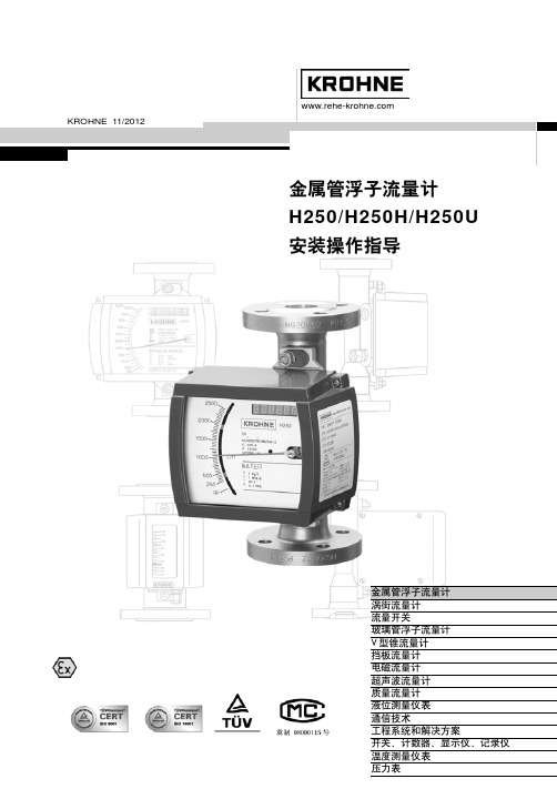
KROHNE 11/2012
!"#$% H250/H250H/H250U !"#
s
!"#$% !" ! !"#$% !" !" !" !"# ! !"# ! !"#$%& ! ! !"#
!"#$%&'(
H250 !"#$%&'()$*+, !"#$%&'()*+,-. !"#$%&'()*+,-. !"#$%&'()*+,-./0+123)456 !" !"#$% ! !"# 39 !"#$%&'()*+,-./012345 ! " #$%&
!"
H250
!"#
7
! H250H ! !"W
!"#$%&'
!"#$%&'()*
!"#$ !"#$%&
!"#!$%&'(')*+,-#./0$123
=2.
=
!"#$%&'()*+,-#$./ ! !"#$ !"# 1:2 !"#$ !"# 1:5 1:2 9 !" !"# #$% TIV C4
!"# $ ! DIN 2501 DN mm 15 25 50 80
!"#$%&'()*+,$-./012 !" G M9
KROHNE FPD3100系列正向流量计说明书

Positive DisPlacement Flow meter For corrosive liquiDsFPD3100 SeriesU P PS BodyU T emperatures up to80ºC (176ºF)U N PT or BSP ThreadsThe FPD3100 Series positive displacement flow meters are affordable and accurate. One primary feature is the ability to maintain consistent accuracy despite changing viscosity conditions. The meter’s solid construction and excellent dynamic response are well suited to the measurement of many corrosives as well as other non-abrasive fluids. Since there is no need for straight run piping upstream or downstream of the flow meter, the FPD3100 flow meters are simple to use and to install. The meter has good resolution and high accuracy at low flow rates.SPeCiFiCaTioNS accuracy: ±0.5% of readingRepeatability: ±0.03%Fitting Type: NPT: FemaleB SP: “-BSP” optionHall-effect Sensor Power: 4.5 to24 Vdc (7.5 mA)Reed Sensor Power: 30 Vdc (500 mA)output options: Pulse output: Standard NPN 4 to 20 ma Transmitter:“-D-a” option; no output on battery powered “-D” modelDisplay: 7-digit/12 mm (0.47") upper,7-digit/7 mm (0.28") lower all “-D” options ate: User definedTotal: Resettable accumulated-Total: Non-resettableFPD3105Minimum Viscosity: 1cPs Maximum Viscosity: 1000 cPs standard Maximum Pressure: See chart on next page Strainer Size: See ordering chart on next page Mounting: Shafts must be in a horizontal plane electrical Connections: 2 x 12 mm (0.08 x 0.47"), fittings included “-D-a” option Cable Length: 1 m (3') stripped ends, non-display models Mounting: Pipe Power: 4 to 20 mA, “-D-a” models 18 to 30 Vdc display, “-D” models 3 Vdc lithium battery (included)Liquid Temperature: -40 to 80°C (-40 to 176°F), -20 to 60ºC (-4 to 140ºF) for display models Materials Body and Rotors: PPS Seals: FKM, FEP (FPD3105) Fasteners: Stainless steelCable insulation:PVCShaft: Hastelloy C enclosure: NEMA 6 (IP67)FFPD3105D-a Both models shownsmaller than actual size.100%50%Pressure Drop vs. ViscosityFor units with a battery powered digital display add “-D” to the model number, for an additional charge.For units with a DC powered digital display and 4 to 20 mA output add “-D-A” to the model number, for an additional charge.For units with BSP connections add “-BSP” to the model number, no additional charge.F Dimensions: mm (inch)Display Module (-D or -D-a)119 (4.7)141 (5.6)(-D or -D-A)109(4.3)FPD310564(2.52)43 (1.7)100 (3.9)(-D or -D-A)FPD3102 and FPD3103。
KROHNE科隆玻璃转子流量计

KROHNE科隆玻璃转子流量计原装德国krohne科隆玻璃转子流量计请拨:158★0506▶1213科隆超声波物位计OPTISOUND3010/3020/3030、科隆雷达物位计OPTIFLEX1100/1300 BM702 BM102 OPTIW AVE6300/7300、科隆磁翻板液位计BM26、科隆磁致伸缩液位计KMR、科隆电磁流量计OPTIFLUX2100/4100/2300/4300、科隆质量流量计OPTIMASS1300C、科隆流量开关DW181/182/183/184、科隆金属转子流量计H250 DK32 DK37、科隆玻璃转子流量计DK800 V A40 GA24等•模块化设计,应用广泛•测量范围最高可达250 bar - 3750 psi•高负荷和温度稳定性OPTIBAR P 1010 C压力变送器适用于工业测量领域的通用测量。
其隔膜材质为1.4435/AISI316L,具有良好的耐腐蚀性。
仪表的模块化设计提供了多种过程连接、压力范围和电气接口的组合选择,涵盖了几乎所有工业应用要求。
亮点:•带1.4435/AISI316L不锈钢隔膜的全焊接压力测量元件•精度:±0.25%•零点时出色的温度稳定性•测量范围:0.1-250 bar / 4-3750 psi•模块化设计•防护等级可达IP68•cULus认证行业:•土木工程•环境工程•发电厂•工厂自动化•液压气动系统•泵和压缩机应用:•气体和液体的绝压和表压测量OPTIBAR P 2010 C带平焊隔膜的卫生型压力变送器•模块化设计,应用广泛•适合SIP/ CIP•卫生型过程连接OPTIBAR P 2010 C压力变送器专用于食品和制药行业。
尤其适用于全封闭的测量,可提供长期稳定的可重复测量信号,适合定期的SIP/ CIP清洗,同时又能保证高度的耐腐蚀性。
设备的模块化设计使其具有多种多样的全焊接过程连接来适应各种不同的测量介质,并可有多种电气连接选择,几乎可以满足任何工业卫生过程测量要求。
Krohne电磁流量计操作与维护

差压式流量计的分类
差压式流量计分类如表所示:
分类原则
按产生差压的 作用原理分类 按结构形式分 类
按用途分类
分类类型
1)节流式;2)动压头式;3)水力阻力式; 4)离心式;5)动压增益式;6)射流式
1)标准孔板;2)标准喷嘴;3)经典文丘 里管;4)文丘里喷嘴;5)锥形入口孔板; 6)1/4圆孔板;7)圆缺孔板;8)偏心孔板; 9)楔形孔板;10)整体(内藏)孔板;11) 线性孔板;12)环形孔板;13)道尔管; 14)罗洛斯管;15)弯管;16)可换孔板 节流装置;17)临界流节流装置
工作原理
流量方程
式中 qm--质量流量,kg/s; qv--体积流量,m3/s; C--流出系数; ε--可膨胀性系数; β--直径比,β=d/D; d--工作条件下节流件的孔径,
m; D--工作条件下上游管道内径,
m; △P--差压,Pa; ρl--上游流体密度,kg/m3。
由上式可见,流量为C、ε、d、ρ、 △P、β(D)6个参数的函数,此6个参 数可分为实测量[d,ρ,△P,β(D)] 和统计量(C、ε)两类 。
在同样差压下,经典文丘里管和文丘里喷嘴的压力损失约为孔板与喷嘴的 1/4-1/6。而在同样的流量和相同的β值时喷嘴的压力损失只有孔板的30%-50%。
在相同阻流件类型和直径比情况下,经典文丘里管的必要直管段长度比孔板 与喷嘴的要小得多。
测量易使节流件沾污、磨损及变形的被测介质时,廓形节流件较孔板要优越 得多。
1)标准节流装置;2)低雷诺数节流装置; 标准孔板 3)脏污流节流装置;4)低压损节流装置; 5)小管径节流装置;6)宽范围度节流装置;
标准喷嘴
7)临界流节流装置;
差压式 流量计
- 1、下载文档前请自行甄别文档内容的完整性,平台不提供额外的编辑、内容补充、找答案等附加服务。
- 2、"仅部分预览"的文档,不可在线预览部分如存在完整性等问题,可反馈申请退款(可完整预览的文档不适用该条件!)。
- 3、如文档侵犯您的权益,请联系客服反馈,我们会尽快为您处理(人工客服工作时间:9:00-18:30)。
200 300 200 300 200 300 200 300 200(180) 200(180) 175
170
DN50
2″
M9/ESK M9/HT/ESK M9/ESK-Z M9/HT/ESK-Z M9/K M9/HT/K M9/KD M9/HT/KD M7/ESK M7/K M7/KD
M7/P
H 250
H 250
可变面积 流 量 计 H250— — 一种全金属结构的浮子流量计
简述
H 250 流 量 计 是 适 用 于 测 量 液 体 和 气 体 的 全 金 属 结 构 金 属 管 浮 子 流 量 计 。 相 对 应 测 量 介 质 的 某 一 流 量 ,磁 性 浮 子 在 测 量 管 中 对 应 一 个 浮 子 位 置 ,这 个 浮 子 位 置 通 过 指 示 器 中
DN 15, DN 25, DN 50 / PN 40; DN 80, DN 100 / PN
16 1/2”- 4” / 150 lbs / RF 或 300 lbs / RF DN15, DN25 /PN40, (1/2″,1″ /150 lbs/RF) φ12
DN15, DN25/PN40, DN50, DN80, DN100/PN25 高压型和其它特殊型号可根据用户要求提供
H250 流 量 计 可 选 配 M7 或 M9 指 示 器
M9 指示器功能和特点
■ 在 指 示 器 中 采 用 一 块 耦 合 磁 钢 完 成 流 量 指 示 ,电 信 号 转 换 ;具 有 为 控 制 流 量 波 动 而 设 计 的 阻 尼 功 能,使仪表运行更加安全 可靠。
■ 采 用 模 块 化 组 合 设 计 ,可 在 现 场 快 速 的 给 仪 表 增 加 电 信 号 输 出 ,上 下 限 开 关 ,流 量 累 积 功 能 ,各 功 能 单 元 板 为 插 装 结 构 ,具 有 更 换 部 件 简 单 ,方 便,定位准确的特点。
三线制接线,内置微型放大器的限位开关可 直 接 与 可 编 程 控 制 器 ( PLC) 连 接 使 用 。 开关的工作状态
铝片切割起始器槽(有效面积关)时开关发 出报警信号。
限位开关接线图 n EEx ia 或 EEx ib 认 证 的 开 关 放 大 器 与
n M9 指 示 器 内 部 的 模 块 导 轨 可 以 插 装 所 有 要 加 装 的 电 气 部 件 。 n ESK、 ESK-Z、 K1 或 K2 等 电 气 部 件 和 刻 度 盘 均 可 很 方 便 地 插 装 到 模 块 导 轨 上 。 n 更换模块时无需将介质断流。 n 如介质超过仪表所允许的最高温度,只要安装一个适配器,指示器就可适用于新的介质条件。 n 流量部分可采用不同材质来适应不同的介质条件。 n 流量计可根据用户要求加装阻尼装置和磁过滤器。
100
165(125) 300(170) 75 100 200(125) 300(170) 120 195(170) 145(100) 200(100) 95
90
150(105)
250(145)
70
85
200(105)
300(145)
110(105)
160(145)
135(90)
175(90)
85
85
300
M7/ESK
180(145)
M7/K
200(145)
M7/KD
130
M7/P
125
代 号 HT=高 温 型 , 括 号 中 的 介 质 温 度 只 适 用 于 温 度 ≥ 100℃ 的 耐 热 电 缆 。
180(150) 300(235) 80 130 200(150) 300(235) 130 295(235) 165(110) 200(110) 105
M7 指 示 器 功 能 和 特 点
■ 就地指示器线性流量指示 ■ 可选择安装:
- 4-20mA 线 性 输 出 ESK 变 送 器 - 0.02-0.1Mpa 气 动 信 号 变 送 器 。 -上 下 限 报 警 开 关
电 磁 兼 容 性 (EMC)
可变面积流量计 型 号 : H 250 M9 / ESK
1) 机 壳 盖 2) 刻 度 盘 3) ESK 累 积 板 4) 模 块 导 轨 5) 限 位 开 关 6) ESK 变 送 器 7) 测 量 部 件
3
H 250
H 250
技术参数
用户应严格遵照仪表的技术参数应用条件
仪表型号
£ £H250
测 量 范 围 (100%点 值 ), 从 流 量 表 中 选 择
接近开关
指示器
SC 3.5-N0 (2-线 制 ) M9 SJ 3.5-E2 (3 线 制 ) M9 SC 2-N0 (2 线 制 ) M7 SJ 3.5-E2 (3 线 制 ) M7
最大数量 2 2 2 2
2- 线 制 接 线 的 限 位 开 关 符 合 DIN 19234(NAMUR)标 准 , 可 以 应 用 于 危 险 场 合 。 3线 制 连 接 的 限 位 开 关 使 用 10~30 V DC 电 压 供 电。限位开关的位置可以直接在刻度盘上设置。 二线制接线的限位开关需要连接一个 WE77/Ex,KMD 或 KFH 晶 体 管 放 大 器 才 能 工 作 。
200 300 180 300 200 300 200 300 190(150) 200(150) 145
150
M9/ESK
200
M9/HT/ESK
300
M9/ESK-Z
150
DN80/100
3″ , 4″
M9/HT/ESK-Z 270
M9/K
200
M9/HT/K
300
M9/KD
190
M9/HT/KD
介质温度 ≤ 85℃ ≤ 100℃ ≤ 135℃ ≤ 180℃
5
H 250
H 250
带 ESK。 ESK-Z, KD, P 时 的 最 高 介 质 温 度 ( Tp)
H250/RR,H250/Hastelloy C4/Ti
300℃ 见 下 表
H250/PTFE
70℃
仪表口径 类型
DIN DNmm
ANSI inches
水 : 20℃ 空 气 : 1.013 bar abs。 20℃
量程比 精度等级
H250/RR, H250/C4/(Ti )
25- 100, 000l/h 0.7- 600 m³/h 10: 1
VDI/VDE 3513,Sh.2 1.6
H250/PTFE
2.5
测量管
H250/RR, H250/C4/(Ti)
不锈钢加 PTFE 衬 里
密封面钛衬
哈 氏 合 金 C4 ( 2.4610)
密 封 面 PTFE 衬里
钛材
哈 氏 合 金 C4 ( 2.4610)
PTFE
ቤተ መጻሕፍቲ ባይዱ
钛材
哈 氏 合 金 C4 ( 2.4610)
PTFE
标准孔板 AL2 O3
7
H 250
H 250
远距离开关信号输出
限位开关
每个指示器上可以安装一个或两个限位开关。
KROHNE 01/2002
金 属 管 浮 子 流 量 计 H 250
国 家 认 可 注 册 号 : SC 08
注 册 证 号 : CCQE0899A0136
国际认可论坛 多边承认协议 ( AF/ MAL)
集团承认
金属管浮子流量计 涡街流量计 流量开关 电磁流量计 超声波流量计 质量流量计 液位测量仪表 通信技术 系统
最 高 介 质 温 度 (Tp )
-25℃ ~+70℃
-80℃ ~+300℃ -80℃ ~+300℃
带 ESK, ESK-Z, 用 于 防 爆 场 所 时 , 须 符 合 防 爆 温
度组别的规定值
环境温度
组别
≤ 40℃
T6
≤ 60℃
T5
≤ 60℃
T4
≤ 60℃
T3
环 境 温 度 (Ta)
<70℃
<120℃ -25℃ ~+60℃
非危险场合下应用
Ta<40℃ ( 环 境 温 度 ) Ta<60 ℃ ( 环 境 温 度 ) Tp in ℃ ( 介 质 温 度 ) Tp in ℃ ( 介 质 温 度 )
DN15/25
1/2″ ,1″
M9/ESK M9/HT/ESK M9/ESK-Z M9/HT/ESK-Z M9/K M9/HT/K M9/KD M9/HT/KD M7/ESK M7/K M7/KD
■ 采 用 最 新 型 的 ESKII 信 号 转 换 器 兼 有 HART 协 议 通 讯 功 能 。 可 用 PC 机 或 HART协 议 手 持 通 讯 器 现场进行技术参数的重新设定。
■ 可在就地流量指示型仪表内选择安装: - 带 4~20mA 线 性 输 出 和 HART 协 议 并 无 磁 滞 后 的 ESKII 信 号 转 换 器 ( 本 安 型 ) - 带 有 6 位 LED 显 示 的 流 量 累 积 单 元 板 。 -带有上限,下限报警开关的单元板。
仪表口径
法兰连接 只 对 于 H250/RR。 H250/C4/Ti 带有保温夹套 食品型连接
DN 15- DN 150
DN 15- DN 100 DN 15, DN 25 / PN 40 DN 50, DN 80, DN 100 / PN
25
连接
DIN 2501 法 兰 ANSI B 16.5 法 兰 只 对 于 H250/RR。 H250/C4/Ti 保温夹套法兰 保温夹套管 DIN 11851 食 品 型 标 准 特殊类型