工频3000W纯正弦波逆变器的参数
大功率逆变器 规格书

3000W 修正波DC-AC逆变器■特性:修正波输出(THD<3%)瞬间功率高达6000W效率高达85%保护各类:电池高低压保护/输出短路保护/过负载保护/过温度保护/输入反接保护/电池低压警报应用:家电,电动工具,办公和便携式设备,车辆和游艇等。
1年保修电气规格型号BEM3000L输出额定功率(Typ.) 3000W 3000W 3000W交流电压220V 220V 220V频率50HZ±0.5HZ50HZ±0.5HZ50HZ±0.5HZ波形额定电压下, 修正波(THD<3%) 额定电压下, 修正波(THD<3%) 额定电压下, 修正波(THD<3%)输入电池电压12V 24V 48V电压范围(Typ.) 10V-15V 20V-30V 40V-60V 直流电流(Typ.) 277A 138A 69A空载损耗≤0.3A ≤0.2A ≤0.15A 关机模式电流≤20mA ≤20mA ≤20mA 效率(Typ.) ≥90% ≥90% ≥90% 电池类型铅酸电池铅酸电池铅酸电池电池输入保护保险片35A*12 35A*6 35A*6电池低压警报10.5V±0.5V20V±1V42V±2V电池低压保护9.5V±0.5V19V±1V40V±2V电池高压保护15.5V±0.5V30V±1V60V±2V电池反接保护通过内部保险片通过内部保险片通过内部保险片输出保护过温度75℃±5℃75℃±5℃75℃±5℃亮红色指示灯,有报警声,无输出亮红色指示灯,有报警声,无输出亮红色指示灯,有报警声,无输出输出短路红绿灯交替闪,取消短路后自动恢复正常红绿灯交替闪,取消短路后自动恢复正常红绿灯交替闪,取消短路后自动恢复正常过负载(Typ.)≥3000W ≥3000W ≥3000W亮红色指示灯,自锁,降低负载重启恢复正常输出亮红色指示灯,自锁,降低负载重启恢复正常输出亮红色指示灯,自锁,降低负载重启恢复正常输出USB 输出电压5V 5V 无输出电流2A 500mA 无环境工作温度0-40℃@100%负载工作湿度20-90%RH,无冷藏储存温度、湿度-30℃-+70℃,10-95%RH其它重量净重:4.8 Kg 毛重:6 Kg 尺寸454*180*142 mm(L*W*H)包装490*245*205 mm(L*W*H)备注如未特别说明,所有规格参数25℃环境温度下进行量测。
3000W纯正弦波逆变器的详细过程

3000W纯正弦波逆变器的详细过程什么是逆变器逆变器是把直流电能(电池、蓄电瓶)转变成交流电(一般为220V,50Hz正弦波)。
它由逆变桥、控制逻辑和滤波电路组成。
简单地说,逆变器就是一种将低压(12或24伏或48伏)直流电转变为220伏交流电的电子设备。
因为我们通常是将220伏交流电整流变成直流电来使用,而逆变器的作用与此相反,因此而得名。
什么是正弦波逆变器逆变器可以按照它的输出波形进行分类,分为方波逆变器、修正波逆变器和正弦波逆变器。
因此正弦波逆变器的定义就是输出波形为正弦波的逆变器。
它的优点是输出波形好,失真度很低,且其输出波形与市电电网的交流电波形基本一致,实际上优良的正弦波逆变器提供的交流电比电网的质量更高。
正弦波逆变器对收音机和通讯设备及精密设备的干扰小,噪声低,负载适应能力强,能满足所有交流负载的应用,而且整机效率较高;它的缺点是线路和相对修正波逆变器复杂,对控制芯片和维修技术的要求高,价格较贵。
正弦波逆变器实物图工作原理在介绍正弦波逆变器工作原理之前,先介绍一下逆变器的工作原理。
逆变器是一种DCtoAC的变压器,它其实与转化器是一种电压逆变的过程。
转换器是将电网的交流电压转变为稳定的12V直流输出,而逆变器是将Adapter输出的12V直流电压转变为高频的高压交流电;两个部分同样都采用了用得比较多的脉宽调制(PWM)技术。
其核心部分都是一个PWM集成控制器,Adapter用的是UC3842,逆变器则采用TL5001芯片。
TL5001的工作电压范围3.6~40V,其内部设有一个误差放大器,一个调节器、振荡器、有死区控制的PWM发生器、低压保护回路及短路保护回路等。
输入接口部分:输入部分有3个信号,12V直流输入VIN、工作使能电压ENB及Panel电流控制信号DIM。
VIN由Adapter提供,ENB 电压由主板上的MCU提供,其值为0或3V,当ENB=0时,逆变器不工作,而ENB=3V时,逆变器处于正常工作状态;而DIM电压由主板提供,其变化范围在0~5V之间,将不同的DIM值反馈给PWM控制器反馈端,逆变器向负载提供的电流也将不同,DIM值越小,逆变器输出的电流就越大。
工频纯正弦波逆变器

工频纯正弦波逆变器说明书目录目录 (2)一.特点 (3)二.面板说明 (4)三.技术参数 (5)四.安装 (6)1.连接示意图 (6)2.使用导线平方数 (6)3.安装指南 (7)4.远程控制安装 (7)五.蓄电池类型选择 (7)六.工作原理 (9)1.充电阶段解释 (9)2.充电曲线图 (9)七.使用说明 (10)八.应用领域 (10)1.家庭娱乐 (10)2.家庭设备 (10)3.办公设备 (11)4.照明设备 (11)九.状态指示及故障对照表 (11)一. 特点z安静,高效率运作z前面板LED指示灯和可调开关选择器z可选设置铅酸电池,胶体电池,或玻璃纤维隔板(AGM)电池等 z70A自动三阶段充电(大电流充电,吸收,和浮充 )z快速开关(栅板到电池和电池栅板)的备用电源z较低的闲置电流能和发动机一致,在没有负载情况下节约能源. z在极端环境条件下具有持久的寿命z高负载能力可以承担比较大的负载,在过载情况下能稳定处理 z电路板涂层可以保护他们免遭腐蚀及提高使用寿命和可靠性z持久的粉末涂层,耐腐蚀钢底盘,具有防水功能z保护功能:a)过电压和低电压保护b)高温保护c)自动过载保护d)短路保护二. 面板说明正面面板交流输出端面板 市电输入零线 市电输入火线 机器输出地线市电输入地线 机器输出零线 机器输出火线远程指示灯三. 技术参数输入波形 正弦波(实用工具或发电机)标称输入电压 120V 230V低压跳闸 90V ±4% 184V/154V ±4% 低压重启 100V ±4% 194V/164V ±4% 高压跳闸 140V ±4% 253V ±4% 高压重启 135V ±4% 243V ±4% 交流最大输入电压 150V 270V额定输入频率 50Hz/60Hz(自动检测)低频跳闸 47Hz-50Hz, 57Hz-60Hz高频跳闸 55Hz-50Hz, 65Hz-60Hz输出波形 与输入波形相同(旁路模式)过载保护 断路器短路保护 断路器最大旁路电流 30安培/40安培在线转换式转换效率 95%以上在线切换时间 10ms (标准)旁路无电池连接 是旁路最大电流 30安/40安旁路过载电流 35安/45安(报警)逆变器规格/输出输出波形 纯正弦波持续输出功率 1000W 1500W 2000W 3000W 4000W 5000W 6000W 持续输出功率 1000V A 1500V A 2000V A 3000V A 4000V A 5000V A 6000V A 功率因数 0.9-1.0输出电压调节 ±10% rms输出频率 50Hz ±0.3Hz 60Hz ±0.3Hz额定效率 大于88%峰值额定值 3000W 4500W 6000 9000 2000 15000 18000 短路保护 是 , 故障后十秒 接蓄电池端面板 直流输入负极 直流输入正极逆变器规格/输入额定输入电压12V 24V 48V最小启动电压10V 20V 40V电瓶低电压报警10.5V 21V 42V电瓶低电压脱扣10V 20V 40V高压报警16V 32V 64V节电器启用时低于25瓦节电器远程均为开关调节充电器模式规格输入电压范围 95-127V AC 194-243V AC/ 164-243V AC(W) 输出电压根据电池类型充电电流35A/70A启动时电瓶初始电压 0-15.7V,12V (*2,24V; *4, 48V)过充保护关断15.7V, 12V (*2,24V; *4, 48V)电瓶类型决定充电器(恒定电流四阶段)数控渐进充电四步走远程控制/RS232/USB 是,可选尺寸(mm) 1000W/1500W/2000W/3000W: 442*218*179mm4000W/5000W/6000W: 598*218*179 mm 重量: 1000W 1500W 2000W 3000W 4000W 5000W 6000W17kg 18kg 20kg 22kg 35kg 38kg 40kg 四. 安装1.连接示意图2.使用导线平方数充电或逆变电流导线长0-1.5 米导线长1.5-4.0米125-180A 50平方 70平方180-330A 70平方 90平方3.安装指南a)将本品与蓄电池组距离尽量拉近b)保持阴凉,干燥以及良好通风c)本品放置方向无关d)无论从原厂购买1.5米长的导线,或者使用你自己的线,都要按照导线平方数表所指明的粗细以确保对直流电流足够粗。
正弦波工频逆变器滤波电容的选配
正弦波工频逆变器滤波电容的选配直流母线电容电压选择:电机控制母线电压除了正常的纹波电压的波动,还包括IGBT动作时电流激烈的变化产生尖峰电压和电机反转时的反电动势,薄膜电容在使用中允许有1.2倍额定电压值的脉冲,理论上可以选择额定电压较低的薄膜电容。
如现在的320V的电机控制器系统一般选用500VDC的薄膜电容,540V的电机控制器系统选用900V或者1000V的薄膜电容。
光伏逆变器交流输出电压270~520V ,薄膜电容选择1100V薄膜电容,高压变频器690V交流输入,选择薄膜电容1100或1200V。
直流母线电容容量选择:在新能源电动汽车电机控制器的应用中,母线电容是以IGBT的载波频率来完成充放电,在一个PWM周期内,IGBT导通时由电池组和电容器同时为电机提供能量,IGBT关断时,电池组向母线电容充电。
我们假设电机控制器的最大输出功率为P,电机控制器的的电路为典型的三相全桥拓扑结构。
在一个开关周期内,母线所提供的能量约为:W=P/(2f)其中:f:IGBT的开关频率。
母线电容一个开关周期内释放的能量为:Q=1/2*C(U+Δu)2-1/2*C(U-Δu)2=2*C*U*Δu其中:U:直流母线电压;Δu:母线纹波电压;在极端情况下:Q=W,进一步计算可得:C=P/(4*f*U*Δu),一般的,直流母线电压的脉动率为5%,即纹波电压值:Δu=U*2.5%综上可得:Cmax=P/(4*f*U*U*2.5%)Cmax值是建立在最极端的情况下,实际应用中,一般认为IGBT 开关导通的时候,母线电容提供W/2的能量,即Q=W/2 结合前面的计算公式可得:Cmin= P/(8*f*U*U*2.5%)在实际应用中更多的电机控制器的母线电容容量的选取接近Cmin的值或者小于Cmin,我们在实际应用中可以根据自己不同的成本和体积综合考虑。
实际应用考虑一些经验值,按照交流输出电流线性配置电容值,比如8~10uF/A。
纯正弦波逆变器 规格书
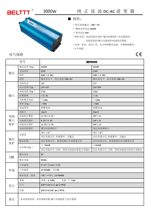
3000W 纯正弦波DC-AC逆变器■特性:●纯正弦波输出(THD<3%)●瞬间功率高达6000W●效率高达90%●保护各类:电池高低压保护/输出短路保护/过负载保护/过温度保护/输入反接保护/电池低压警报●应用:家电,电动工具,办公和便携式设备,车辆和游艇等。
●1年保修电气规格型号BEP3000S输出额定功率(Typ.) 3000W 3000W交流电压220V 220V频率50HZ±0.5HZ50HZ±0.5HZ波形额定电压下, 纯正弦波(THD<3%) 额定电压下, 纯正弦波(THD<3%)输入电池电压12V 24V电压范围(Typ.) 10V-15V 20V-30V 直流电流(Typ.) 276A 138A空载损耗≤3.8A ≤2A关机模式电流≤10mA ≤10mA 效率(Typ.) ≥90% ≥90% 电池类型铅酸电池铅酸电池电池输入保护保险片40A*8 20A*8电池低压警报10.5V±0.5V20V±1V电池低压保护9.5V±0.5V19V±1V电池高压保护15.5V±0.5V30V±1V电池反接保护通过内部保险片通过内部保险片输出保护过温度75℃±5℃75℃±5℃亮红色指示灯,有报警声,无输出亮红色指示灯,有报警声,无输出输出短路亮红色指示灯,取消短路后自动恢复正常亮红色指示灯,取消短路后自动恢复正常过负载(Typ.)≥ 3000W ≥3000W亮红色指示灯,自锁, 降低负载重启恢复正常输出亮红色指示灯,自锁, 降低负载重启恢复正常输出USB 输出电压5V输出电流500mA环境工作温度0-40℃@100%负载工作湿度20-90%RH,无冷藏储存温度、湿度-30℃-+70℃,10-95%RH其它重量净重:6.02Kg 毛重:7.41Kg 尺寸529**180*142 mm(L*W*H)包装558*246*209 mm(L*W*H)备注如未特别说明,所有规格参数25℃环境温度下进行量测。
【DIY第二期】新做的3000W纯正弦波逆变器,已公布全部资料,步步解析原理

【DIY第二期】新做的3000W纯正弦波逆变器,已公布全部资料,步步解析原理展开全文【DIY第二期】新做的3000W纯正弦波逆变器,已公布全部资料,步步解析原理前些时间做了几台了,朋友都拿去用了,说还不错,今天上图大家看一下标称功率3000W持续功率;2800W峰值功率6000W 2S;300次开机短路,200次短路开机过载保护3200W 3S短路立即保护,电池过压/欠压保护齐全前级16管MOS,后级四个50N50整机半成品重4KG看到贴子有这么长了,作为逆变器余业玩家的我甚是感到高兴,时到五一了,也有了点时间打打字了,刚好也马上到了本其DIY结束的时间了,为了方便大家学习和交流,我在这里浅要的说下此款逆变器的设计过程和原理图的局部浅析,小弟专业不精,有说不对的地方请各位高手前辈拍砖!进入正题。
一、此款逆变器的基本情况(架构,组成)总括的说,这是一款24V逆变器,这款逆变器由三个部分组成,1、前级驱动板;2、后级驱动板;3、功率主板。
1、前级驱动板上主要是由三个小部分组成,一个辅助电源部分,一个部分是PWM驱动,第三个部分是保护部分;2、后级驱动板主要由三个部分组成,一个是SPWM信号的产生(单片机完成)部分,一个是硬件RC死区时间设置部分;再一个就是IR2110的驱动部分。
3、功率主板主要由四个部分组成,一个是前级升压及整流滤波,第二个是后级H全桥正弦变换部分,第三个是稳压反馈部分;第四个是LC滤波部分二、电路结构及原理分析1、前级驱动板A、辅助电源电路的功能就是将功24V的电池电压降到13-15V左右然后再经过LM7812稳成12V后供给整机电路的控制部分供电,先上图:在这个电路中,BT 输入电压范围可以达到15-36V,而输出稳定在 12V.Q1也可以用 P 型的MOS 管,适当的选取不同型号的P管可以将电压做到 60V左右。
下面来讲一下这个电路的工作原理,电路起动的瞬间,电源通过R21 提供 Q1足够大的基极电流,Q1饱和导通,其集电极电流一部分通过 L1 给 C121 充电供给负载,一部分储存在 L1 里。
逆变器常规参数介绍

逆变器常规参数介绍逆变器的技术参数主要分为6个部分:直流输入、交流输出、效率、保护、证书与标准、常规参数,想要看懂这些参数并不难,下面在各个部分选择了一些典型的参数做了一些简单介绍。
✧直流输入最大直流电流:逆变器直流侧单路允许输入的直流电流最大值,逆变器的最大直流需要与组件的工作电流和并联组件的数目相一致。
MPPT电压范围:最大功率点跟踪,在运行过程中逆变器需要调节组件的工作电压,使组件始终工作在V-A特性曲线的最大功率点,逆变器可以跟踪的组件的电压范围称为MPPT电压范围,宽的电压范围意味着更高的发电效率。
GoodWe研发生产的逆变器具有更宽的MPPT电压范围。
输入路数:逆变器直流端子的对数,以GW1500-NS和GW3000-NS示例,GW1500-NS输入路数为1,表示可接入一串组件,GW3000-NS输入路数为2,表示可接入两串组件.MPPT路数:光伏逆变器可以跟踪的MPP路数。
MPPT路数与输入路数并不一定相等,输入路数经过并联,然后将电压加载在MPPT电路上。
✧交流输出电网类型:逆变器接入点的电网类型,主要分为两种:单相(L/N/PE),三相(3W/N/PE,3W/PE),根据电网类型可以正确的选择合适的逆变器。
最大交流电流:逆变器交流侧的最大输出电流,逆变器可以短时间工作在最大电流情形下,GoodWe研发生产的逆变器可较长时间工作最大交流电流,以实现发电效率的最大化。
输出范围:电网的变化会导致逆变器输出端的变化,输出范围为逆变器可以根据电网的变化可以自主调节的范围,在保证安全和符合安规的前提下,实现发电效率的最大化。
单相:45Hz~55Hz/55Hz~65Hz;180~270V,三相:45Hz~55Hz/55Hz~65Hz;310~480V/422~528V✧证书与标准并网标准、安规、电磁兼容:中国能标:NB/T 32004,逆变器必须符合能标的标准才可以进行并网。
逆变器技术参数
率
参
数
2KW
3KW
5KW
7.5KW
10KW
输出功率(KW)
2
3
5
7.5
10
最大功率(KW)
2.8
4.2
7
10.5
14
输出波形
正弦波
正弦波
正弦波
正弦波
正弦波
输入电压(交流)
115V
115V/230V
230V
230V
380V
输出电压(交流)
220V
220V
220V/380V
220V/380V
220V/380V
风力发电机专用逆变器技术要求2kw3kw5kw75kw10kw输出功率kw7510最大功率kw284210514输出波形正弦波正弦波正弦波正弦波正弦波输入电压交流115v115v230v230v230v380v输出电压交流220v220v220v380v220v380v220v380v输出频率50hz5转换效率90工作温度3040保护功能过载短路反接过压欠压工作方式连续绝缘电阻20m绝缘强度2kv一分钟db1m50备注
>90%
工作温度
-30℃~40℃
保护功能
过载、短路、反接、过压、欠压
工作方式
连续
绝缘电阻
>20MΩ
绝缘强度
2KV一分钟
噪音等级(dB、1m)
<50
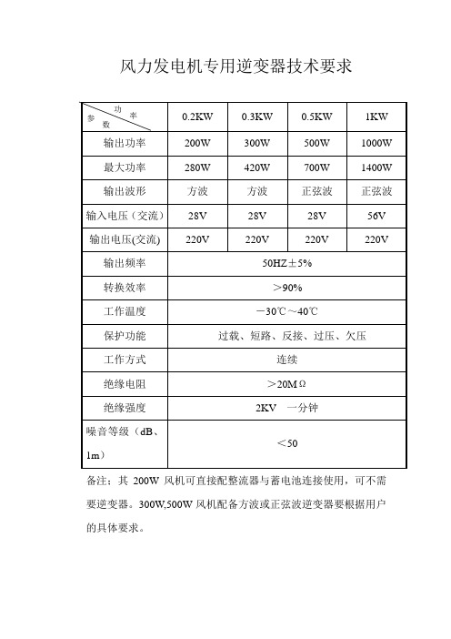
备注;其200W风机可直接配整流器与蓄电池连接使用,可不需要逆变器。300W,500W风机配备方波或正弦波逆变器要根据用户的具体要求。
风力发电机专用逆变器技术要求
输出频率
50HZ±5%
转换效率
>90%
工作温度
-30℃~40℃
3000W逆变器的设计方案
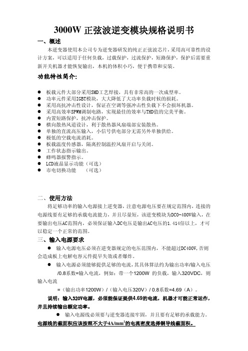
3000W 正弦波逆变模块规格说明书一、概述本逆变器使用本公司专为逆变器研发的纯正正弦波芯片, 采用高可靠性的设 计方案,可以适用于任何负载,过载保护,过流保护,短路保护,保护后需要重 新开关机器才能恢复输出,本机的体积小巧,便于携带和安装。
功能特性简介:板载元件大部分采用SMD工艺焊接,具有非常高的一次成型率。
功率元件采用IGBT模块,大大降低了大功率负载时候的损耗。
采用高抗冲击性设计,保证在空调等强冲击性负载下不会损坏机器。
采用高效率SPWM调制电路,实现最佳的效率与THD值的完美平衡。
内置短路保护,抗冲击保护。
横向散热风道设计,利于散热器风扇端部安装散热。
单独的直流高压输入,小信号供电部分无需另外单独供给。
极低的空载电流消耗。
板载温度传感器,隔离控制温控风扇开启与关闭。
工作状态指示输出。
蜂鸣器报警指示。
LCD液晶显示功能(可选) 市电切换功能 (可选)二、使用方法将足够功率的输入电源接上逆变器,注意电源电压要在规定范围内,连接的 电源线要有足够的承载电流能力,并且尽量短,该逆变模块为DC0-400V输入,在 要输出电压AC范围内,必须保证输入DC电压是输出AC电压的1.414倍以上,才可 以稳定一个正常的范围。
三、输入电源要求输入电源电压必须在逆变器规定的电压范围内,不能超过DC400V,否则 会造成板上电解电容元件提早失效或者爆炸。
输入电源必须能够提供足够的电流, 其具体算法约为输出功率/输入电压 /0.8系数=输入电流,例如:带一个1200W 的负载,输入320VDC,则 输入电流 =(输出功率1200W)/(输入电压320V)/ 0.8系数=4.69(A)。
说明:输入320V电源,必须能保证提供4.69的电流,机器才可能正常运作, 并且持续输出额定功率。
输入电源线必须要与逆变器连接牢固,并且要有足够的承载能力。
电源线的截面积应该按照不大于4A/mm2的电流密度选择铜导线截面积。
3000W PV太阳能逆变器设计
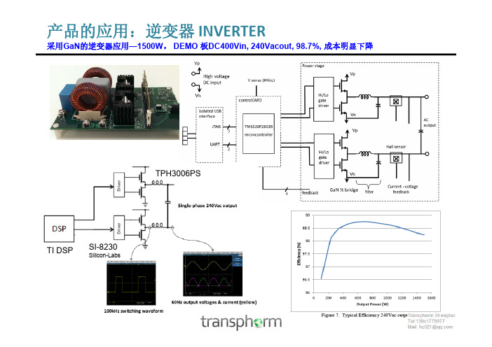
产品的应用:逆变器 INVERTER采用GaN的逆变器应用—1500W, DEMO 板DC400Vin, 240Vacout, 98.7%, 成本明显下降TPH3006PSTI DSPSI-8230Silicon-Labs同样大的逆变器产品,氮化镓的体积减小了一半左右,同时整体成本下降100USD,售价 反提高了100USD. 效率反提高了1.5个点. 4500W, 频率从16K提到到50K 散热器,风散,驱动电路,电感,EMC电路可大大减小体积,还有填充物GaN modules allowed for kW class PV power conditioner with 40% smaller size and loss• • • •Output power 4.5kw (Single Phase 200V) Input voltage 60-400V Maximum Power Efficiency > 98% (vs. >96.5% with Silicon) Volume about 10L <18L (existing Silicon based)Courtesy: Testing done and published by Yaskawa Electric.40% volume reduction >40% loss reduction微型逆变器应用传统线路 输出采用600V的低频工 作MOSFET 无‘无功补偿’ 新的设计需要输出逆变 高频化以尽可能提高无 功补偿 氮化镓适合高频,高效+L1G DD1 C1+传统的采用变压器升压400V 因氮化镓支持大比例升压且高效率达98以上。
逆变器主要技术参数

逆变器主要技术参数:
逆变器技术参数
逆变器型号
设备招标定
输出额定功率
500KW
最大交流侧功率
520KW
最大交流电流
1070A
最高转换效率
98.5%
*欧洲效率
98.3%
输入直流侧电压范围
480-880
最大功率跟踪(MPP)范围
480Vdc~820Vdc
最大直流输入电流
1200A
交流输出电压范围
额定270 VAC
有
过电压保护(有/无)
有பைடு நூலகம்
其它保护(请说明)
极性反接保护、短路保护、孤岛效应保护、过热保护、过载保护、接地故障保护等
工作环境温度范围
-20℃~+40℃
相对湿度
0~95%,不结露
满功率运行的最高海拔高度
≤2000米(超过2000米需降额使用)
工频变压器正弦波逆变

工频变压器正弦波逆变工频变压器正弦波逆变是一种常见的电力转换方式,它将输入的工频交流电转换为输出的正弦波交流电。
这种逆变方式在许多电力应用中都发挥着重要作用,例如家用电器、工业设备以及电力系统中的无功补偿等。
工频变压器正弦波逆变的基本原理是利用变压器的特性,将输入电压通过变压器的变比变换,从而得到所需的输出电压。
变压器的输入侧接入工频交流电源,输出侧则接入负载。
当输入电压为正弦波时,变压器会将输入电压的变化传递到输出侧,从而使输出电压也成为正弦波。
通过适当选择变压器的变比,可以实现输入电压和输出电压之间的变换。
在工频变压器正弦波逆变中,变压器起到了关键的作用。
变压器是一种电磁设备,由两个或多个线圈(即主线圈和副线圈)共用磁路构成。
当主线圈中有交流电流通过时,会在磁路中产生磁场。
这个磁场会通过磁耦合的方式传递到副线圈中,从而在副线圈中产生感应电动势。
通过合理选择主线圈和副线圈的匝数比例,可以实现输入电压和输出电压之间的变换。
例如,如果主线圈的匝数是副线圈的两倍,那么当主线圈中有1V的输入电压时,副线圈中就会有2V的输出电压。
这样,就实现了电压的升降转换。
工频变压器正弦波逆变的优点在于输出电压的波形质量高,具有较低的谐波含量。
这使得逆变器能够提供高质量的电力供应,适用于对电压波形要求较高的电器设备。
此外,由于工频变压器正弦波逆变不需要使用任何电子器件,因此具有较高的可靠性和稳定性。
总的来说,工频变压器正弦波逆变是一种简单而有效的电力转换方式。
它通过利用变压器的特性,将输入的工频交流电转换为输出的正弦波交流电。
这种逆变方式在电力应用中发挥着重要作用,为各种电器设备提供稳定和高质量的电力供应。
逆变器的主要参数

逆变器的主要参数The Standardization Office was revised on the afternoon of December 13, 2020光伏逆变器的主要参数1 .额定输出电压在规定的输入电源条件下,输出额定电流时,逆变器应输出的额定电压值。
(电压波动范围:单相 220V±5%,三相 380±5%。
)• 2.输出电压的稳定度在光伏系统中,太阳电池发出的电能先由蓄电池储存起来,然后经过逆变器逆变成220V或380V的交流电。
但是蓄电池受自身充放电的影响,其输出电压的变化范围较大,如标称12V的蓄电池,其电压值可在10.8~14.4V之间变动(超出这个范围可能对蓄电池造成损坏)。
对于一个合格的逆变器,输入端电压在这个范围内变化时,其稳态输出电压的变化量应不超过额定值的±5%,同时当负载发生突变时,其输出电压偏差不应超过额定值的±10%。
3.输出电压的波形失真度对正弦波逆变器,应规定允许的最大波形失真度(或谐波含量)。
通常以输出电压的总波形失真度表示,其值应不超过5%(单相输出允许l0%)。
由于逆变器输出的高次谐波电流会在感性负载上产生涡流等附加损耗,如果逆变器波形失真度过大,会导致负载部件严重发热,不利于电气设备的安全,并且严重影响系统的运行效率。
4.额定输出频率对于包含电机之类的负载,如洗衣机、电冰箱等,由于其电机最佳频率工作点为50Hz,频率过高或者过低都会造成设备发热,降低系统运行效率和使用寿命,所以逆变器的输出频率应是一个相对稳定的值,通常为工频50Hz,正常工作条件下其偏差应在±l%以内。
5.负载功率因数表征逆变器带感性负载或容性负载的能力。
正弦波逆变器的负载功率因数为0.7~0.9,额定值为0.9。
在负载功率一定的情况下,如果逆变器的功率因数较低,则所需逆变器的容量就要增大,一方面造成成本增加,同时光伏系统交流回路的视在功率增大,回路电流增大,损耗必然增加,系统效率也会降低。
Invertek 600 3000W 纯正弦波太阳能逆变器用户手册说明书
Invertek pure sine wave solar inverter 600/3000WUser’s manualContentsManual instruction----------------------------------------------------------------------------------------------------------------------3 Important safety instructions---------------------------------------------------------------------------------------------------------3 1. Product introduction-----------------------------------------------------------------------------------------------------------------5 1.1. General function description-------------------------------------------------------------------------------------------------5 1.2. Series models introduction---------------------------------------------------------------------------------------------------7 1.3. Electrical specifications-------------------------------------------------------------------------------------------------------7 1.4. Audible alarm--------------------------------------------------------------------------------------------------------------------8 1.5. Environmental specifications------------------------------------------------------------------------------------------------9 1.6. Fan control-----------------------------------------------------------------------------------------------------------------------9 1.7. Power limitation-----------------------------------------------------------------------------------------------------------------9 1.8. Short circuit protection--------------------------------------------------------------------------------------------------------91.9. Over load protection---------------------------------------------------------------------------------------------------------102. Installation and operation--------------------------------------------------------------------------------------------------------10 2.1. Unpacking and inspection--------------------------------------------------------------------------------------------------10 2.2. Handling and storage--------------------------------------------------------------------------------------------------------11 2.3. Front panel description and operation-----------------------------------------------------------------------------------12 2.4. Rear panel description and operation-----------------------------------------------------------------------------------152.5. Installation----------------------------------------------------------------------------------------------------------------------153. Maintenance and troubleshooting---------------------------------------------------------------------------------------------18 3.1. Preventative maintenance-------------------------------------------------------------------------------------------------18 3.2. Troubleshooting guide------------------------------------------------------------------------------------------------------18Manual instructionPurposeThe purpose of this manual is to provide explanations and procedures for operating, maintaining, and troubleshooting the pure sine wave inverter. This manual should be read through carefully before installations and operations. Please retain this manual for future reference.ScopeThis document defines the functional requirements of pure sine wave inverter, intended for worldwide use in electronic processing equipment. The inverter unit shall contain a fan for forced air-cooling. The inverter may be used singly or in redundant configurations. All manuals are applicable under all operating conditions when installed in the end use system, unless otherwise stated.Order of precedenceThis manual is intended for anyone who needs to install and operate the inverter. In the event of a conflict between this manual and references cited herein, this manual shall take precedence.OrganizationThis manual is composed of three chapters.Chapter 1: product introduction contains the information about general description, features and specifications of inverter.Chapter 2: installation and operation provides the information about installation and operation of inverter.Chapter 3: maintenance and troubleshooting contains the information of how to maintain and troubleshoot inverter.Important safety instructionsGeneral safety precautions1. Before installing and using the inverter, read all instructions and cautionary markings on the inverter andall appropriate sections of this guide. Be sure to read all instructions and cautionary markings for any equipment attached to this unit.2. This unit is designed for indoor use only. Do not expose the inverter to rain, snow, or spray.3. To reduce risk of fire hazard, do not cover or obstruct the ventilation openings. Do not install the inverterin a zero-clearance compartment.4. Use only attachments recommended or sold by the manufacturer. Doing otherwise may result in a risk offire, electric shock, or injury to persons.5. To avoid a risk of fire and electric shock, make sure that existing wiring is in good condition and that wireis not undersized. Do not operate the inverter module with damaged or substandard wiring.6. Do not operate the inverter module if it has received a sharp blow, been dropped, or otherwise damagedin any way.Precautions when working with batteriesTo avoid personal injury and property damage, read these battery precautions on handling, charging and disposing batteries.1. Not reverse INPUT+ and INPUT- to battery.2. Keeps the battery away from heat sources including direct sunlight, open fires, microwave ovens, andhigh-voltage container? Temperatures over 60ºC may cause damage. Make sure the area around the battery is well ventilated.3. Never smoke or allow a spark or flame near the engine or batteries.4. Use caution to reduce the risk or dropping a metal tool on the battery. It could spark or short circuit thebattery or other electrical parts and could cause an explosion.5. Remove all metal items, like rings, bracelets, and watches when working batteries.6. Have plenty of fresh water and soap nearby in case battery acid contacts skin, clothing, or eyes.7. If battery acid contacts skin or clothing, wash immediately with soap and water. If acid enters your eye,immediately flood it with running cold water for at least twenty minutes and get medical attentionimmediately.8. If you need to remove a battery, always remove the grounded terminal from the battery first. Make sure allaccessories are off so you don’t cause a spark.1. Product introduction1.1. General function descriptionThe pure sine wave inverter adopts many superior features and is designed based on the highest standards in the industry. The advanced high frequency infrastructure with pure sine wave output is perfectly designed for diverse applications including home, office, and heavy-duty industrial power environments. The inverter can operate independently. However, the unique optional N+X parallel redundancy structure design can maximize the expansibility of integrating additional units to the inverter system in the future. Pure sine wave inverter promises to provide the extraordinary performance in terms of reliability and flexibility all environments from home to heavy-duty industrial.1.1.1. FeaturesØAdopts new pure sine wave inverter topologyØHigh power density with superior reliability and performanceØSurge rating: 2 * power ratingØInput/output isolated designØOptional N+X redundancy functionØDesign for harsh environment and various equipmentsØ“All master” dynamic mechanism eliminate single point failure to optimize reliabilityØPure sine wave output(THD<3%) for wide range of applications and harsh environmentØOutput frequency: 50/60Hz switch selectableØLow power “power saving mode” to conserve energyØCapable of driving highly reactive & capacitive loads at start momentØLED indicators displayØAdvanced DSP controlØProtection: input low voltage/overload/short circuit/low battery alarm/input over voltage/over temperature/high output voltage/low output voltage/unit internal failure/unit parallel failure1.1.2. ApplicationPower tools: circular saws, drills, grinders, sanders, buffers, weed and hedge trimmers, air compressors. Office equipment: computers, printers, monitors, facsimile machines, scanner.Household items: vacuum cleaners, fans, fluorescent and incandescent lights, shavers, sewing machines. Kitchen appliances: coffee makers, blenders, ice markers, toasters.Industrial equipment: metal halide lamp, high – pressure sodium lamp.Home entertainment electronics: television, VCRs, video games, stereos, musical instruments, satellite equipment.1.2. Series models introductionTo fulfill the diverse environments and power demands, the pure sine wave inverter has complete lines for meeting the requirements from the clients. The inverter system ranges from 600W to 3000W that can fulfill the majority power demands from home, small business to industrial heavy-duty environment.1.2.1. Product linePart number DescriptionInvertek600/120 600W inverter (I/P: 12VDC, O/P: 120VAC)Invertek1000/120 1000W inverter (I/P: 12VDC, O/P: 120VAC)Invertek2000/120 2000W inverter (I/P: 12VDC, O/P: 120VAC)Invertek3000/120 3000W inverter (I/P: 12VDC, O/P: 120VAC)Invertek600/220 600W inverter (I/P: 12VDC, O/P: 220VAC)Invertek1000/220 1000W inverter (I/P: 12VDC, O/P: 220VAC)Invertek2000/220 2000W inverter (I/P: 12VDC, O/P: 220VAC)Invertek3000/220 3000W inverter (I/P: 12VDC, O/P: 220VAC)1.2.2. Physical specifications:Inverter mechanicalModel Dimension(L*W*H) mm Weight Invertek600 270(L)*160(W)*70(H) 2.2KgInvertek1000 355(L)*180(W)*82(H) 4.0KgInvertek2000 425(L)*245(W)*95(H) 7.5KgInvertek3000 495(L)*245(W)*95(H) 9.5Kg600W dimension (mm)1000W dimension (mm)2000W dimension (mm)3000W dimension (mm)1.2.3. CertificationCertification CESafety Comply with EN60950, UL-458 StandardEMCFCC part 15 class B; EN55022 Class B; IEC61000-4-2; IEC61000-4-3;IEC61000-4-4; IEC61000-4-5; IEC61000-4-61.3. Electrical specificationsNominal voltage 12VDC Operating range 10VDC~15VDC Output waveform Pure sine wave Surge rating 2*power rating Nominal output voltage 110/115/120VAC 220/230/240VACOutput voltage regulation±5% Output frequency50/60Hz ±0.1%Output current @110/115/120Invertek600/120 5.45A/5.22A/5AInvertek1000/120 9.09A/8.70A/8.33AInvertek2000/120 18.18A/17.39A/16.67AInvertek3000/120 27.28A/26.09A/25AOutput current @220/230/240Invertek600/220 2.73A/2.61A/2.50AInvertek1000/220 4.55A/4.35A/4.17AInvertek2000/220 9.10A/8.70A/8.34AInvertek3000/220 13.65A/13.05A/12.51ACrest factor 3:1THD <3%, linear load;<5%, non-linear load;Peak output current@110/115/120 Invertek600/120 10.92A/10.44A/10AInvertek1000/120 18.2A/17.4A/16.68AInvertek2000/120 36.4A/34.8A/33.36AInvertek3000/120 54.6A/52.2A/50.04APeak output current@220/230/240 Invertek600/220 5.46A/5.22A/5.00AInvertek1000/220 9.10A/8.70A/8.34AInvertek2000/220 18.20A/17.40A/16.68AInvertek3000/220 27.3A/26.1A/25.02APeak efficiency > 90%No load current drawInvertek600/1000 <12WInvertek2000/3000 <20W Stand-by current drawInvertek600/1000 <6WInvertek2000/3000 <10WPower saving recovery time 5 secondsProtection Overload, short circuits, reverse polarity,Over/under input voltage, over temperature,Over/under output voltage, unit internal failure,Unit in-parallel failure1.4. Audible alarmItem Alarm mode Beep mode RemarkInput level<battery-low level or >battery-high level1 Alarm Beep 1 time/1sLoad>150%2 Alarm Beep 2 time/1s Power limitation by temperature3 Alarm Beep 3 time/1s Fan fault4 Fault Beep always All fault modeSwitch on/off Chirp one time When switch on/off the unit 5Remote on/off Chirp one time When remote switch on/off the unit 1.5. Environmental specificationsOperating temperature Operation temperature: –20°C to +70°C –5°C to 40°C with full performanceStorage temperature -30°C to 70°COperating humidity 90% relative humidity(no condense) Noise <50dBOperating attitude 1500MForce cooling Load and temperature controlled cooling fan 1.6. Fan controlLoad level and temperature Fan speed Load<=10% and temperature<=40℃0Else Full speed 1.7. Power limitation½¼¾Temperature (°C)Power de-rating V.S. ambient temperature1.8. Short circuit protectionShort circuit protection algorithm consists of 2 stages:Stage 1: power limited during short circuitThe short current is set as the normal value for inverter, if output voltage is less than 40VAC and output current is higher than 2A for 4 cycles, Inverter will judged as short circuit fault maybe happened, and the short circuit protection algorithm will go to the second stage.Stage 2: unit resumed from short circuit conditionThe short current is regulated to 50% normal value, if output voltage is less than 50VAC and output current is higher than 2A for 30 seconds, the inverter system will consider the short circuit occurs, and the short current is set to a small value (4A), otherwise the short circuit alarm will be cleared.1.9. Over load protectionOver load protection consists of 2 stages:Stage 1: The overload protection will happen if the load power exceeds the rated power. With the conditions of 20s of 125% overload/10s of 150% overload/5s of 200% overload, the inverter system will judge as overload and de-rate the output power less than the rated power. Then the protection algorithm goes to the second stage.Stage 2: The inverter system remains operating with the de-rating power. If the load power is less than 10% for 10s, the system will recover back to the normal operation status.2. Installation and operation2.1. Unpacking and inspectionOnce receiving your pure sine wave inverter, remove the unit from its packaging and inspect it for scratches, cracks, broken connection. Your purchase of inverter unit should ship with the manual. If you want to add other more modules into the system achieve parallel function, you can choose the propositional packaging, if any missing or damage is discovered, repack the unit and return it to the original place of purchasing.Packing of inverterIn addition, some optional accessories are available could work with pure sine wave inverter. Please base on your application and then choose the suitable package.Part name Function descriptionFigureSync-hub-4A necessary kit for the in-parallel application. It can make modules parallel and achieve synchronized operationMax. in-parallel ports: 42.2. Handling and storageIf the inverter is going to be stored, it should be stored in a cool, dry, well-ventilated location where the rain, splashing water, chemical agents, etc. will not reach based on the environment specification standard. The equipment should be covered with a tarpaulin or plastic wrapper to protect it from dust, dirt, paint, or other materials.The equipment can be lifted from the front panel by drawing out the handle. Firstly, screw off the steel bolt, then drawing out the handle until the whole module out. When the inverter module has to be installed in the shelf, the bolt should be screwed down.2.3. Front panel description and operationFront panel view (1000W)2.3.1. LED indicatorRefer to the above figure. There are 3 dual color LED indicators on the front panel: 1. Unit status indicator, 2. Load level indicator, 3. Input voltage indicator.1. Unit status indicatorSolidInverter okay Blink(slow) Power saving Green LEDBlink(fast) Unit starting SolidEEPROM faultBlink(slow) Unit start failure(DC-DC circuit) Orange LEDBlink(fast) Unit start failure(DC-AC circuit)SolidOver temperatureBlink(slow) Unit internal failure(DC-DC circuit)Red LEDBlink(fast)Short circuitOrange and red interchanged(slow) Unit internal failure(DC-AC circuit)Orange+red LED Orange and red interchanged(fast)Unit in-parallel failure2. Load level indicatorLED status OFF Green solid Orange solid Red solid Red blink 600W0~30W30~198W198~450W450~576WOver 576WPower saving / Frequency settingAC output outletLED indicatorParallel portCom. port1000W 0~50W 50~330W 330~750W 750~960W Over 960W 2000W 0~100W 100~660W 660~1500W 1500~1920W Over 1920W 3000W 0~150W 150~990W 990~2250W 2250~2880W Over 2880W3. Input voltage indicatorLED status Battery cut-off level(12VDC)Load level 0~29% 30~69% 70~100%Red solid <10.3VDC <10.2VDC <10VDCRed blink 10.3~11.3VDC 10.2~11.2VDC 10~11.0VDCGreen solid 11.3~14VDC 11.2~13.9VDC 11.0~13.7VDCOrange blink 14~15VDC 13.9~14.9VDC 13.7~14.7VDCOrange solid >15VDC >14.9VDC >14.7VDC2.3.2. Power saving/frequency setting1. Power saving mode can be set by 3 dip switches, SW1, SW2 and SW3 on front panel. For example: when the power saving watt setting is 15W, if load level>15W, the inverter will go to normal operation; if load level<15W, the inverter will go to the power saving mode.Invertek600 Invertek1000 Invertek2000/3000 SW1 SW2 SW3 Disable Disable Disable OFF OFF OFF 13W 20W 40W ON OFF OFF 35W 50W 100W OFF ON OFF 60W 80W 160W ON ON OFF 85W 110W 220W OFF OFF ON 85W 110W 220W Others2. Frequency can be set by a dip switch SW4 on front panel.Frequency S4 Status50Hz OFF60Hz ON2.3.2. AC outlets600W1000W2000W&3000WGFCI*1GFCI*1NEMA 5-15R(2 position)*2Schuko*1Schuko*1Schuko*1Universal*1Schuko*1, hardwireSchuko*2, hardwireIEC(2 position)*1Universal*1, hardwireGFCI*1, hardwireNEMA 5-15R(2 position)*1 IEC(2 position)*1Universal*2, hardwireAustralia/New Zealand*1 NEMA 5-15R(2 position)*1IEC(4 position)*1, hardwireUnited Kingdom*1Australia/New Zealand*1,hardwireNEMA 5-15R(2 position)*2,hardwireUnited Kingdom* 1, hardwireAustralia/New Zealand*2,hardwireIEC*1, hardwireUnited Kingdom*2, hardwireNEMA 5-20R(2 position)*12.4. Rear panel description and operationRear panel view (1000W)Main switchON: Located the switch to “On”, the machine power on.OFF: Located the switch to “OFF”, the machine power off.REMO: Located the switch to “REMO”, the machine can be switched on or off remotely by wired remote control.Remote control portConnect the remote control to the port.Ground terminalConnect the GND to the ground terminal.Please using #6 AWG wire to connect vehicle chassis.The inverter should be installed in a location that meets the following requirements:n Dry — Do not allow water to drip or splash on the invertern Safe — Do not install in a battery compartment or other areas where flammable fumes may exist, such as fuel storage areas or engine compartmentn Ventilated — Allow at least one inch of clearance around the inverter for air flow. Ensure the ventilation opening on the rear and front of the unit are not obstructedn Dust — Do not install the inverter in a dusty environments where are dust, wood particles or other filings/shavings are present. Dust can be pulled into the unit when the cooling fan is operatingn Close to batteries — Avoid excessive cable lengths but do not install the inverter in the same compartment as batteries. Also do not mount the inverter where it will be exposed to the gases produced by the battery. These gases are very corrosive and prolonged exposure also will damage the inverterM6 screwPVC WIRE AWG#2, #2/0, #4, #4/0TerminalBattery to inverter cable connection2.5.2. Battery connectionStep 1-Following battery polarity guide located near battery terminal! Place the battery cable ring terminal over inverter’s battery terminal. Tighten the M6 nut. Do not place anything between the flat partof battery terminal and the battery cable ring terminal, or overheating may occur.Caution! DO NOT place anything between battery cable ring terminals and battery terminals. The terminal stud is not designed to carry current. Apply anti-oxidant paste to terminals after terminals have been torqued.Step 2- Connect battery cables to your batteriesl Single battery connection:when using a single battery, its voltage must be equal to the voltage of pure sine wave inverter nominal input voltage.Caution! For the user operation safety, we strongly recommend that you should isolate the battery terminals before you start to operate the unit. If you parallel more batteries to extend the backup time, please make sure that you already use tapes to isolate the rest battery terminals before you start to operating the unit.l Parallel battery connection:when using multiple batteries in parallel, each battery’s voltage must be equal to the voltage of pure sine wave inverter nominal input voltage.DC wiring connectionsPlease be noted that connect the battery cables to the DC input terminals of the pure sine wave inverter. Your cables should be as short as possible (ideally, less than 6 feet/1.8 meters) enough to handle the required current in accordance with the electrical codes or regulations application. Cables are not an adequate gauge (too narrow) or too long will decrease the inverter performances such as poor surge capability and low input voltage warnings frequently and shutdowns.If the cables longer or narrower, the greater the voltage drop. Increasing your DC cable size will help improve the situation.The following cable recommendations are for the best performance of inverter (apply both 120V and 220V versions).Model P/N Wire AWG Inline fuseInvertek600 # 4 120AInvertek1000 # 2 160AInvertek2000# 2/0 320AInvertek3000# 4/0 480AWarning:1. Connect the cables to the power input terminals on the rear panel of the inverter. The red terminal is positive (+) and black terminal is negative (-). Insert the cables into the terminals and tighten screw to clamp the wires securely2. Also, use only high quality copper wire and keep cable length short, a maximum of 3-6 feet. Make sure all the DC connections are tight. Loose connections could result overheat in a potential hazard.3. Carefully check that all wiring is disconnected from any electrical sources. Do not connect the output terminals of the inverter to an incoming AC source.2.5.3. AC connectionBefore having AC connection, match the power requirements of connected devices with the power output of pure sine wave inverter to avoid overload. Consult a qualified electrician, follow local code for the proper outlet connectors and select the correct outlet (reference 2.3.3. AC outlet).3. Maintenance and troubleshooting3.1. Preventative maintenanceThe following preventive maintenance routines should be considered as a minimum requirement. Your installation and site may require additional preventive maintenance to assure optimal performance from your installed inverter and associated equipment. These routines should be performed twice a year (more often if required). We strongly recommend a contract with pure sine wave inverter customer support services for preventive and remedial maintenance. The technician or electrician performing preventive maintenance on the equipment must read and understand thoroughly this manual and be familiar with the indicators, controls, and operation of the equipment.3.2. Troubleshooting guideIf the inverter fails to operate properly, use the troubleshooting table to determine the probable cause(s) and solution(s) to resolve error conditions. For unlisted error conditions, please contact your local dealer for technical assistances.Troubleshooting tableError condition Possible cause RecommendationNo AC output and all LEDs off Lack of input power1. Check if input cables are all firmlyconnected to power source.2. Check if power source is not yet switchedon, or is low in power.3. Check if input cables are connected tocorrect polarity, positive to positive, negative to negative(reverse connect will lead to the fuse open, need be repaired).No AC output and status LED isred/blink(fast) Short circuit1. Check if the devices connect to the ACoutput is damaged.Turn off the input power source, remove theload and check the connection, then switchon the input power to restart the inverter.No AC output and status LED isred/blink(slow) Audible alarm: beep always Unit internal failure(DC-DC circuit)Reboot the inverter unit, If the inverter cannot work normally; suggest to send the unitback to supplier.No AC output and status LED isred/solidAudible alarm: beep always Over temperature1. The inverter has been overheated, switchoff the inverter and the consumer, and waitfor approx. 2 minutes and switch on theinverter only, suggest reduce the loadingand make sure that a better ventilation forthe inverter is given ,Then switch on theconsumer again.No AC output and status LED is orange/blink(fast) Audible alarm: beep always Unit start failure(DC-AC circuit)Reboot the inverter unit, if the inverter cannot work normally; suggest to send the unitback to supplier.No AC output and status LED is orange/blink(slow) Audible alarm: beep always Unit start failure(DC-DC circuit)Reboot the inverter unit, if the inverter cannot work normally; suggest to send the unitback to supplier.No AC output and status LED isorange red /blink (red one time and Yellow one time (slow)) Audible alarm: beep always Unit internal failure(DC-AC circuit)Reboot the inverter unit, if the inverter cannot work normally; suggest to send the unitback to supplier.No AC output and status LED isorange red/blink(red one times and yellow one time(slow)) Audible alarm: beep always Unit in-parallel failure1. Check if output power cables areconnected to correctly;2. Check if parallel communication cablesare connected to correctly.No AC output and input level LEDis red solidAudible alarm: beep 1 time/1s Input voltage lower thanoperatingrange(10~15V)No AC output and input level LEDis orange solidAudible alarm: beep 1 time/1s Input voltage higherthan operatingrange(10~15V)Ensure input voltage in 10V~15VDC range.AC output exists and beep alarm3 times per second Fan failureReboot the inverter system, if the invertercan not work normally, suggest to send theunit back to supplier.。
逆变器技术参数范文

逆变器技术参数范文1.输入参数-输入电压范围:逆变器能够接受的输入电压范围,如220VAC或380VAC。
-输入电流:逆变器在正常工作负载下所需的输入电流。
-输入频率范围:逆变器能够接受的输入频率范围,如50Hz或60Hz。
2.输出参数-输出电压范围:逆变器可以提供的输出电压范围,如220VAC或380VAC。
-输出电流:逆变器在正常工作负载下所能提供的输出电流。
-输出频率范围:逆变器可以提供的输出频率范围,如50Hz或60Hz。
-波形失真率:输出电压波形的失真程度,一般以百分比表示。
-功率因数:逆变器的功率因数,即输出电流与输出电压之间的相位关系。
3.效率-逆变器的效率:逆变器的能量转换效率,一般以百分比表示。
-静态功耗:逆变器在空载或负载较小时的功耗值。
4.控制方式-PWM控制:逆变器采用脉宽调制(PWM)方式控制输出电压和频率。
-MPPT控制:逆变器采用最大功率点跟踪(MPPT)控制方式,以最大限度地提高太阳能电池板的输出功率。
- 智能控制:逆变器具有智能管理和监控功能,可以通过手机应用程序或Web界面进行远程监控和控制。
5.保护功能-过载保护:逆变器具有过载保护功能,当负载过大时会自动切断输出电流保护逆变器和负载设备。
-短路保护:逆变器具有短路保护功能,当负载出现短路时会自动切断输出电流保护逆变器和负载设备。
-过温保护:逆变器具有过温保护功能,当逆变器温度超过一定限制时将自动降低输出功率或切断输出电流。
-过压保护:逆变器具有过压保护功能,当输出电压超过一定限制时会自动降低输出功率或切断输出电流。
-低压保护:逆变器具有低压保护功能,当输出电压低于一定限制时会自动降低输出功率或切断输出电流。
6.其他功能与特点-并网功能:逆变器具备将太阳能电能与电网连接的功能,可以将多余的电能注入电网。
-电池储能功能:逆变器具备与电池连接并进行储能的功能,可以在停电情况下提供备用电力。
-可调工作模式:逆变器具备可调的工作模式,用户可以根据需要调节逆变器的输出特性。
床车用3000正弦波逆变器

床车用3000正弦波逆变器全文共四篇示例,供读者参考第一篇示例:床车用3000瓦正弦波逆变器是一种专门为床车提供电力供应的设备,逆变器可以将直流电转换为交流电,适用于各种电子产品。
在床车上使用正弦波逆变器可以提供稳定的电力输出,保证床车上的电子设备能够正常工作。
床车用3000瓦正弦波逆变器通常由直流输入端、交流输出端、控制单元和散热系统等组成。
直流输入端主要接入床车上的电池,将电池产生的直流电转换成交流电;交流输出端则输出转换后的交流电,供给床车上的各种电子设备使用;控制单元主要对逆变器的工作状态进行监控和控制;散热系统则负责散热,确保逆变器的稳定工作。
床车用3000瓦正弦波逆变器具有很多优点。
正弦波逆变器可以产生与市电相同的交流电,电压稳定,波形纯正,不会对床车上的电子设备造成损害,可以更好地保护床车上的设备。
正弦波逆变器的效率较高,能够有效地将床车上的电池供应的电能转换成电子设备所需的电能,节约能源。
正弦波逆变器体积小、重量轻,便于携带和安装,方便床车使用者进行移动和操作。
不过,床车用3000瓦正弦波逆变器也存在一些不足之处。
价格相对较高,普通消费者可能难以承受;功率不够大,无法为一些大型电子设备提供电力供应;在使用过程中需要注意保护好逆变器,避免受潮或受到撞击等。
第二篇示例:床车用3000正弦波逆变器是一种能够将直流电能转换为交流电能的装置,通常用于床车或其他设备的电力供应。
正弦波逆变器可以提供稳定的电源输出,使设备可以有效地运行,并且可以防止电力波动对设备造成损害。
本文将探讨床车用3000正弦波逆变器的原理、特点和应用场景。
正弦波逆变器的原理是通过将直流电压转换为交流电压,从而实现电力的转换。
在逆变器中,直流电压首先经过变压器变换为交流电压,然后经过整流、滤波等环节得到稳定的正弦波输出。
正弦波逆变器的输出电压波形与家用电源相同,具有较高的质量和稳定性,适用于各种电器设备的供电。
床车用3000正弦波逆变器具有多种特点,使其成为众多设备的理想选择。
逆变器的主要参数

光伏逆变器的主要参数之邯郸勺丸创作1 .额外输出电压在规定的输入电源条件下,输出额外电流时,逆变器应输出的额外电压值. (电压动摇规模:单相220V±5%,三相380±5%.)• 2.输出电压的稳定度在光伏系统中,太阳电池收回的电能先由蓄电池储存起来,然后经过逆变器逆酿成220V或380V的交流电.但是蓄电池受自身充放电的影响,其输出电压的变更规模较大,如标称12V的蓄电池,其电压值可在10.8~14.4V之间变动(超出这个规模可能对蓄电池造成损坏).对于一个合格的逆变器,输入端电压在这个规模内变更时,其稳态输出电压的变更量应不超出额外值的±5%,同时当负载产生突变时,其输出电压偏差不该超出额外值的±10%.3.输出电压的波形失真度对正弦波逆变器,应规定允许的最大波形失真度(或谐波含量).通常以输出电压的总波形失真度暗示,其值应不超出5%(单相输出允许l0%).由于逆变器输出的高次谐波电流会在理性负载上产生涡流等附加损耗,如果逆变器波形失真度过大,会导致负载部件严重发烧,晦气于电气设备的平安,并且严重影响系统的运行效率.4.额外输出频率对于包含电机之类的负载,如洗衣机、电冰箱等,由于其电机最佳频率任务点为50Hz,频率过高或者过低都会造成设备发烧,降低系统运行效率和使用寿命,所以逆变器的输出频率应是一个相对稳定的值,通常为工频50Hz,正常任务条件下其偏差应在±l%以内.5.负载功率因数表征逆变器带理性负载或容性负载的能力.正弦波逆变器的负载功率因数为0.7~0.9,额外值为0.9.在负载功率一定的情况下,如果逆变器的功率因数较低,则所需逆变器的容量就要增大,一方面造成成本增加,同时光伏系统交流回路的视在功率增大,回路电流增大,损耗必定增加,系统效率也会降低.6.逆变器效率逆变器的效率是指在规定的任务条件下,其输出功率与输入功率之比,以百分数暗示,一般情况下,光伏逆变器的标称效率是指纯阻负载,80%负载情况下的效率.由于光伏系统总体成本较高,因此应该最大限度地提高光伏逆变器的效率,降低系统成本,提高光伏系统的性价比.目前主流逆变器标称效率在80%~95%之间,对小功率逆变器要求其效率不低于85%.在光伏系统实际设计过程中,不单要选择高效率的逆变器,同时还应通过系统合理配置,尽量使光伏系统负载任务在最佳效率点邻近.7、额外输出电流(或额外输出容量)暗示在规定的负载功率因数规模内逆变器的额外输出电流.有些逆变器产品给出的是额外输出容量,其单位以VA或kVA暗示.逆变器的额外容量是当输出功率因数为1(即纯阻性负载)时,额外输出电压为额外输出电流的乘积.8、呵护措施一款性能优良的逆变器,还应具备完备的呵护功效或措施,以应对在实际使用过程中出现的各类异常情况,使逆变器自己及系统其他部件免受损伤.(1)输入欠压保户:当输入端电压低于额外电压的85%时,逆变器应有呵护和显示.(2)输入过压保户:当输入端电压高于额外电压的130%时,逆变器应有呵护和显示.(3)过电流呵护:逆变器的过电流呵护,应能包管在负载产生短路或电流超出允许值时及时动作,使其免受浪涌电流的损伤.当任务电流超出额外的150%时,逆变器应能自动呵护.(4)输出短路保户逆变器短路呵护动作时间应不超出0.5s.(5)输入反接呵护:当输入端正、负极接反时,逆变器应有防护功效和显示.(6)防雷呵护:逆变器应有防雷呵护.(7)过温呵护等.另外,对无电压稳定措施的逆变器,逆变器还应有输出过电压防护措施,以使负载免受过电压的损害.9.起动特性表征逆变器带负载起动的能力和动态任务时的性能.逆变器应包管在额外负载下可靠起动.10.噪声电力电子设备中的变压器、滤波电感、电磁开关及电扇等部件均会产生噪声.逆变器正常运行时,其噪声应不超出80dB,小型逆变器的噪声应不超出65dB.。
3000w逆变器工作原理

3000w逆变器工作原理
嘿呀!今天咱们就来好好聊聊3000w 逆变器的工作原理!哇,这可是个相当有趣的话题呢!
首先呀,咱们得搞清楚啥是逆变器?哎呀呀,简单说,逆变器就是把直流电变成交流电的装置。
那3000w 这个数字又是啥意思呢?这表示它的功率大小呀!
那3000w 逆变器到底咋工作的呢?
1. 输入直流电!通常呢,这直流电可能来自电池,比如太阳能板储存的电能呀。
这直流电就像一群乖乖排队的小朋友,规规矩矩地等着变个魔法。
2. 内部的电路开始发挥作用啦!有各种芯片、晶体管啥的,哎呀呀,它们可都是大功臣呢!它们会控制电流的通断,就像指挥交通的警察叔叔一样,让电流按照特定的规律流动。
3. 经过一系列复杂的操作,直流电的电压和电流就开始发生变化啦!这时候,就像是给直流电施了魔法,它们逐渐从整齐的队伍变成了跳跃的音符。
4. 最后,神奇的事情发生啦!直流电就变成了交流电,成功“变身”!可以为各种需要交流电的设备供电啦,比如咱们家里的电器啥的。
哇塞!是不是感觉很神奇?但是这里面的技术可复杂着呢!比如说,要保证输出的交流电稳定、纯净,可不能有啥杂波干扰呀。
哎呀呀,这就需要很多精密的控制和滤波电路。
再想想,如果逆变器工作不正常了,那可就麻烦啦!所以在设计和制造的时候,质量可一定要过关呢!
总之呀,3000w 逆变器的工作原理虽然复杂,但了解了之后,是不是觉得很有趣呀?哎呀,科技的力量真是强大呢!。
- 1、下载文档前请自行甄别文档内容的完整性,平台不提供额外的编辑、内容补充、找答案等附加服务。
- 2、"仅部分预览"的文档,不可在线预览部分如存在完整性等问题,可反馈申请退款(可完整预览的文档不适用该条件!)。
- 3、如文档侵犯您的权益,请联系客服反馈,我们会尽快为您处理(人工客服工作时间:9:00-18:30)。
苏州日不落能源设备有限公司地址:江苏 苏州 金阊科技产业园A-504
● ●
邮编:215000
电话:+86 512 68638910 传真:+86 512 68638916
SPT3000-112 SPT3000-124 SPT3000-148 SPT3000-212 SPT3000-224 SPT3000-248 3000W 9000W 12VDC 24VDC 100/110/120VAC±5% 50/60Hz±0.5% 0.1~1 83% 86% 88% <10W <10ms 190~245VAC 10.0~16.0VDC 20.0~31.0VDC 42.0~62.0VDC 10.0~16.0VDC 20.0~31.0VDC 42.0~62.0VDC 70A 40A 20A LED红色 UL458 FCC Part15 ClassA -20~40℃ 20~90%RH -30~70℃ 负载控制冷却风扇 24 460*220*190(L*W*H) 车载,游艇,太阳能系统,移动设备,工控,电动工具和家庭办公等 *备注:以上规格参数若有修改,恕不另行通知。 LVD(EN60950) CE (EN55022:2006+A1:2007) 70A 40A 20A 85% 87% 90% 48VDC 12VDC 24VDC 220/230/240VAC±3% 48VDC
参数
型号 输出功率 冲击功率 输入电压 输出电压 输出频率 功率因素 满载效率 待机损耗 切换时间 输入AC电压范围 输入电压范围 DC充电电流 故障指示 安规认证 电磁干扰 工作温度 工作湿度 内储藏温度 冷却 重量(kg) 尺寸(mm) 运用
SPT3000系列
充电型纯正弦波逆变器-SPT系列 特点
●纯正弦波输出内含充电功能 ●输入输出完全隔离设计 ●高效率设计 ●具有省电模式 ●适应于容性、感性负载 ●7断路器 ●高级微处理控制系统设计 ●输入反接/欠压/过压/短路/过载/超温保护 ●远程控制
E-mail: info@
Web:
