Orange PI GPIO控制详细教程
GPIO用法及应用流程

GPIO用法及应用流程(也含其他设备的用法和配置)(GPIO用于STM32的IO处电平、信号的输入输出)1)定义一个GPIO结构体GPIO_InitTypeDef GPIO_InitStructure; (为了向GPIO外设内写数据)2)开启GPIOx口的时钟外设:(可以一次设置多个用(。
|。
)形式)RCC_APB2PeriphClockCmd( RCC_APB2Periph_GPIOx,ENABLE);——GPIO配置时都是用APB2,也就说这个语句在GPIO中就是这个样子。
3)选择引脚GPIO_InitStructure.GPIO_Pin = GPIO_Pin_0;4)设置GPIO输出模式GPIO_InitStructure.GPIO_Mode = GPIO_Mode_Out_PP;(1)浮空输入:In_Floating(2)带上拉输入:IPU(In Push_Up)(3)带下拉输入:IPD(In Push_Down)(4)模拟输入:AIN(Anolog In)(5)开漏输出:OUT_PD(OD 代表开漏,既Open Drain,OC代表开集,Open Collect)(6)推挽输出:OUT_PP(PP代表推挽式,Push_Pull)效果例:三个灯轮流亮每刻有且只有一个灯亮(7)复用功能推挽输出:AF_PP(AF代表复用功能,Alternate-Fuction)(8)复用功能开漏输出:AF_OD5)设置引脚速率GPIO_InitStructure.GPIO_Speed = GPIO_Speed_50MHz;6)调用库函数初始化GPIO(注:每次只能初始化一个引脚)GPIO_Init(GPIOB, &GPIO_InitStructure); (如果要控制其他引脚,重复上面的3和6有时也会用到4步,总的来说配置一个GPIO至少要有1—6步)另外:GPIO_SetBits(GPIOx, GPIO_Pin_i|GPIO_Pin_j); ——对所有端口进行置1操作(高电平)GPIO_ResetBits(GPIOx,GPIO_Pin_i); ——对所有端口进行置0操作(低电平)GPIO_WriteBits(GPIOx, GPIO_Pin_i,1); ——对一个端口进行写1(也可以写0,把括号内的1改为0即可)操作GPIO_Write(GPIOA, 0x1101);——向指定GPIO数据端口写入数据GPIO库函数:函数名描述GPIO_DeInit 将外设GPIOx寄存器重设为缺省值GPIO_AFIODeInit 将复用功能(重映射事件控制和EXTI设置)重设为缺省值GPIO_Init 根据GPIO_InitStruct中指定的参数初始化外设GPIOx寄存器GPIO_StructInit 把GPIO_InitStruct中的每一个参数按缺省值填入GPIO_ReadInputDataBit 读取指定端口管脚的输入GPIO_ReadInputData(GPIOx,GPIO_Pin_i) 读取指定的GPIO端口输入GPIO_ReadOutputDataBit(GPIOx,GPIO_Pin_i) 读取指定端口管脚的输出位(0|1)GPIO_ReadOutputData(GPIOx,GPIO_Pin_i) 读取指定的GPIO端口输出GPIO_SetBits 设置指定的数据端口位GPIO_ResetBits 清除指定的数据端口位GPIO_WriteBit 设置或者清除指定的数据端口位GPIO_Write 向指定GPIO数据端口写入数据GPIO_PinLockConfig 锁定GPIO管脚设置寄存器GPIO_EventOutputConfig 选择GPIO管脚用作事件输出GPIO_EventOutputCmd 使能或者失能事件输出GPIO_PinRemapConfig 改变指定管脚的映射GPIO_EXTILineConfig(GPIO_PortSourceGPIOA, GPIO_PinSource0); 选择GPIO管脚用作外部中断线路(例子是让PA0引脚作为中断线路),中断触发时该线将中断输出。
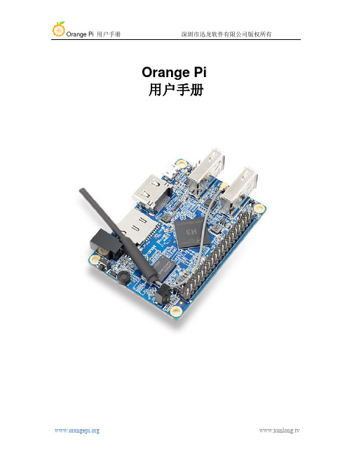
OrangePi用户手册中文版

Orange Pi 用户手册目录一.Orange Pi简介 (3)1.我们可以用Orange Pi做什么 (3)2.Orange Pi 是为谁设计的 (3)3.硬件特性的介绍 (3)4.外观规格的介绍 (4)5.开发板使用方法 (6)6.SD卡的制卡介绍 (8)7.通用软件的配置 (18)8. GPIO规格介绍 (25)9.CSI摄像头接口规格 (26)二. Linux内核源码编译 (28)1.源码的获得方法 (28)2.项目源码的编译 (29)3.内核镜像和库的安装 (31)三. Android源码编译介绍 (34)1.JDK 的安装 (35)2.安装平台支持软件 (35)3.源码包的获得方法 (36)4.编译工具链的安装 (36)5.lichee 源码的编译 (37)6.android源码的编译 (37)四.工程化配置介绍 (41)1.工程配置化文件的个性化配置 (41)2. Uboot 和boot 更新方法 (42)3.例子介绍 (42)五.OrangePi驱动程序开发 (46)1.设备驱动和应用程序的编写 (47)2.设备驱动的编译方法 (49)3.应用程序的编译方法 (52)4.驱动和程序的运行方式 (53)六.串口调试工具介绍 (55)Windows平台 (56)1.Windows下USB 驱动安装 (56)2.Windows下Putty 安装 (56)3.调试的连接方式 (57)4.设备信息的获取 (57)5. Putty 的配置 (59)6.开始调试串口 (59)Linux 平台 (60)1.kermit的安装 (60)2.调试的连接方式 (61)3.设备信息的获取 (62)4.开始调试串口 (68)七.常见问题 (70)一. Orange Pi简介什么是 Orange Pi香橙派是一款开源的单板电脑,新一代的 arm 开发板,它可以运行Android4.4、Ubuntu、Debian 等操作系统,兼容树莓派。
树莓派教程1_点亮第一个led灯

树莓派教程1_点亮第一个led灯学习模数电路,从点灯开始;学习51单片机,从点灯开始;学习stm32,从点灯开始;学习DSP,从电灯开始;学习FPGA,从点灯开始;渐渐的,我们已经习惯了用点灯的方式去接触新的事物,不知不觉中,我们已经成为了人们口中常常提到的“一灯大师”。
今天,我们来学习树莓派的使用,依旧从点灯开始,用点灯的方式一步步点亮我们的世界。
实验原理同过树莓派的IO口可以外接很多外设,如舵机、红外发送接收模块、继电器、步进电机、各类兼容传感器、屏幕等。
通过这些外设可以制作很多有趣的设计,改善我们的生活方式提高我们的生活质量。
树莓派的IO口驱动能力是比较弱的,驱动电平为3.3V,高电平驱动比电平驱动能力稍弱些,但这也足够驱动led工作,为方便理解,以下实验以高电平驱动方式进行。
IO口输出高电平,led灯亮,输出低电平则灭。
实验内容•使用面包板和杜邦线连接电路•通过ssh局域网无线连接树莓派•使用wiringPi控制IO•使用vim编辑器实验元器件•树莓派及电源 x1•无线网卡 x1•串口连接器 x1•面包板 x1•Led灯 x1•电阻220欧 x1•杜邦线若干以上器件可在树莓派创客社区淘宝直营店购买:https://52pi.taobao实验步骤一、连接线路。
实物图如下:二、通过ssh连接连接树莓派通过上一课程的学习,已经知道如何通过串口连接树莓派进行联网,接下来学习如何在局域网中通过ssh无线网络连接树莓派,这样摆脱了接串口线的麻烦,方便很多。
1.首先通过串口连接上树莓派,登陆进入树莓派后输入 ifconfig 回车。
可以查看到树莓派的ip地址。
2.电脑打开PuTTY软件,选择SSH模式,输入上面查看的ip地址,端口22,确认无误后点击Open,输入默认用户名密码,登陆完成。
三、使用vi编辑器编写控制代码及编译运行1.登陆树莓派后,输入cd ./wiringPi 进入wiringPi目录,使用vi编辑器编辑c源文件,输入vim.tiny blink.c,如目录下有blink.c文件打开编辑,若无则会新建一个打开编辑。
STM32IO口函数GPIO使用说明

STM32之GPIO条记_zhuan 之阳早格格创做1 STM32的输进输出管足有底下8种大概的摆设:(4输进+2输出+2复用输出)①浮空输进_IN_FLOATING②戴上推输进_IPU③戴下推输进_IPD④模拟输进_AIN⑤开漏输出_OUT_OD⑥推挽输出_OUT_PP⑦复用功能的推挽输出_AF_PP⑧复用功能的开漏输出_AF_OD1.1 I/O心的输出模式下,有3种输出速度可选(2MHz、10MHz战50MHz),那个速度是指I/O心启动电路的赞同速度而不是输出旗号的速度,输出旗号的速度取步调有闭(芯片里里正在I/O心的输出部分安插了多个赞同速度分歧的输出启动电路,用户不妨根据自己的需要采用符合的启动电路).通过采用速度去采用分歧的输出启动模块,达到最好的噪声统造战落矮功耗的手段.下频的启动电路,噪声也下,当不需要下的输出频次时,请采用矮频启动电路,那样非常有好处普及系统的EMI本能.天然如果要输出较下频次的旗号,但是却采用了较矮频次的启动模块,很大概会得到得果然输出旗号.闭键是GPIO的引足速度跟应用匹配(推荐10倍以上?).比圆:1.1.1 对付于串心,假若最大波特率只需115.2k,那么用2M 的GPIO的引足速度便够了,既省电也噪声小.1.1.2 对付于C交心,假若使用400k波特率,若念把余量留大些,那么用2M的GPIO的引足速度或者许不敷,那时不妨采用10M的GPIO引足速度.1.1.3 对付于SPI交心,假若使用18M或者9M波特率,用10M的GPIO的引足速度隐然不敷了,需要采用50M的GPIO的引足速度.1.4 所有端心皆有中部中断本领.为了使用中部中断线,端心必须摆设成输进模式.1.5 GPIO心的摆设具备上锁功能,当摆设好GPIO心后,不妨通历步调锁住摆设推拢,曲到下次芯片复位才搞解锁.2 正在STM32中怎么样摆设片内中设使用的IO端心最先,一个中设通过①摆设输进的时钟战②初初化后即被激活(开开);③如果使用该中设的输进输出管足,则需要摆设相映的GPIO端心(可则该中设对付应的输进输出管足不妨搞一般GPIO管足使用);④再对付中设举止仔细摆设.对付应到中设的输进输出功能有下述三种情况:一、中设对付应的管足为输出:需要根据中围电路的摆设采用对付应的管足为复用功能的推挽输出或者复用功能的开漏输出.二、中设对付应的管足为输进:则根据中围电路的摆设不妨采用浮空输进、戴上推输进或者戴下推输进.三、ADC对付应的管足:摆设管足为模拟输进.如果把端心摆设成复用输出功能,则引足战输出寄存器断开,并战片上中设的输出旗号连交.将管足摆设成复用输出功能后,如果中设不被激活,那么它的输出将不决定.3 通用IO端心(GPIO)初初化:3.1 GPIO初初化3.1.1 RCC_APB2PeriphClockCmd(RCC_APB2Periph_GPIOA | B | C, ENABLE):使能APB2总线中设时钟3.1.2 RCC_ APB2PeriphResetCmd (RCC_APB2Periph_GPIOA | B | C,DISABLE):释搁GPIO复位3.2 摆设各个PIN端心(模拟输进_AIN、输进浮空_IN_FLOATING、输进上推_IPU、输进下推_IPD、开漏输出_OUT_OD、推挽式输出_OUT_PP、推挽式复用输出_AF_PP、开漏复用输出_AF_OD)3.3 GPIO初初化完毕============================================== =========================迩去刚刚开初教习STM32,所以从最基础的GPIO开初教起;最先瞅瞅STM32的datasheet上对付GPIO心的简朴介绍:每个GPI/O 端心有二个32 位摆设寄存器(GPIOx_CRL,GPIOx_CRH),二个32位数据寄存器(GPIOx_IDR,GPIOx_ODR),一个32 位子位/复位寄存器(GPIOx_BSRR),一个16 位复位寄存器(GPIOx_BRR)战一个32 位锁定寄存器(GPIOx_LCKR).GPIO 端心的每个位不妨由硬件分别摆设成多种模式.每个I/O 端心位不妨自由编程,然而I/0 端心寄存器必须按32 位字被考察(不允许半字或者字节考察).GPIOx_BSRR 战GPIOx_BRR 寄存器允许对付所有GPIO 寄存器的读/变动的独力考察;那样,正在读战变动考察之间爆收IRQ 时不会爆收伤害.端心位摆设 CNFx[1:0]=xxb,MODEx[1:0]=xxb再瞅GPIO功能很强盛:1.通用I/O(GPIO):最最基础的功能,不妨启动LED、不妨爆收PWM、不妨启动蜂鸣器等等;2.单独的位树坐或者位扫除:便当硬体做业,步调简朴.端心摆设好以去只需GPIO_SetBits(GPIOx, GPIO_Pin_x)便不妨真止对付GPIOx的pinx位为下电仄;3.中部中断/唤醉线:端心必须摆设成输进模式时,所有端心皆有中部中断本领;4.复用功能(AF):复用功能的端心兼有IO功能等.复位功夫战刚刚复位后,复用功能已开开,I/O 端心被摆设成浮空输进模式:(CNFx[1:0]=01b,MODEx[1:0]=00b).5.硬件沉新映射I/O复用功能:为了使分歧器件启拆的中设I/O 功能的数量达到最劣,不妨把一些复用功能沉新映射到其余一些足上.那不妨通过硬件摆设相映的寄存器去完毕.那时,复用功能便不再映射到它们的本初引足上了;6.GPIO锁定体造:当正在一个端心位上真止了所定(LOCK)步调,正在下一次复位之前,将不克不迭再变动端心位的摆设.GPIO基础树坐GPIOMode_TypeDef GPIO mode 定义及偏偏移天面GPIO_Mode_AIN = 0x0, //模拟输进GPIO_Mode_IN_FLOATING = 0x04, //悬空输进GPIO_Mode_IPD = 0x28, //下推输进GPIO_Mode_IPU = 0x48, //上推输进GPIO_Mode_Out_OD = 0x14, //开漏输出GPIO_Mode_Out_PP = 0x10, //推挽输出GPIO_Mode_AF_OD = 0x1C, //开漏复用GPIO_Mode_AF_PP = 0x18 //推挽复用GPIO输进输出速度采用:typedef enum{GPIO_Speed_10MHz = 1,GPIO_Speed_2MHz,GPIO_Speed_50MHz}GPIOSpeed_TypeDef;#define IS_GPIO_SPEED(SPEED) ((SPEED ==GPIO_Speed_10MHz) ||(SPEED == GPIO_Speed_2MHz) || (SPEED ==GPIO_Speed_50MHz))搞一个GPIO输出的考查当I/O 端心被摆设为推挽模式输出时:输出寄存器上的0 激活NMOS,而输出寄存器上的1 将激活PMOS.用那段步调真止:GPIO_InitStructure.GPIO_Mode =GPIO_Mode_Out_PP;int main(void){#ifdef DEBUG#endif/* 树坐系统时钟 */RCC_Configuration();/* 嵌套中断树坐*/NVIC_Configuration();/* 激活GPIOC clock */RCC_APB2PeriphClockCmd(RCC_APB2Periph_GPIOC, ENABLE);/* Configure PC.04, PC.05, PC.06 and PC.07 as Output pushpull */GPIO_InitStructure.GPIO_Pin = GPIO_Pin_4 | GPIO_Pin_5 | GPIO_Pin_6 |GPIO_Pin_7;GPIO_InitStructure.GPIO_Speed = GPIO_Speed_50MHz; GPIO_InitStructure.GPIO_Mode = GPIO_Mode_Out_PP; GPIO_Init(GPIOC, &GPIO_InitStructure);{/*本考查仅能真止LED1明、熄功能*/GPIO_SetBits(GPIOC, GPIO_Pin_4); //树坐PC.04 pin为下电仄,面明LED1Delay();GPIO_ResetBits(GPIOC, GPIO_Pin_4); //树坐PC.04 pin为矮电仄,燃烧LED1Delay();}}搞一个GPIO输进的考查:以EKSTM32F中LCDdemo搞例子那个考查中把GPIO的PD.04搞为按键输进,当下落沿光临时触收.LCDdemo中的例程如下:最先摆设按键PD.03, PD.04为按键输进交心.void Button_Config(void){GPIO_InitTypeDef GPIO_InitStructure;/* Enable GPIOD clock */RCC_APB2PeriphClockCmd(RCC_APB2Periph_GPIOD, ENABLE);/* Configure PD.03, PD.04 as output pushpull */GPIO_InitStructure.GPIO_Pin = GPIO_Pin_3 | GPIO_Pin_4 ;GPIO_InitStructure.GPIO_Mode =GPIO_Mode_IN_FLOATING;GPIO_InitStructure.GPIO_Speed = GPIO_Speed_50MHz;GPIO_Init(GPIOD, &GPIO_InitStructure);}底下为按键效率是开用中部中断GPIO_EXTILineConfig(GPIO_PortSourceGPIOD,GPIO_PinSource3);EXTI_InitStructure.EXTI_Line = EXTI_Line3; //设定中部中断3EXTI_InitStructure.EXTI_Mode = EXTI_Mode_Interrupt; //设定中断模式EXTI_InitStructure.EXTI_Trigger = EXTI_Trigger_Falling; //设定下落沿触收模式EXTI_InitStructure.EXTI_LineCmd = ENABLE;EXTI_Init(&EXTI_InitStructure);。
安卓开发板OrangePiZero2外接USB无线网卡测试示例

安卓开发板OrangePiZero2外接USB无线网卡测试示例
目前Zero2开发板测试过的能用的USB 无线网卡型号为:
RTL8723BU,其他型号的USB 无线网卡请自行测试,如果无法使用就需要移植对应的 USB 无线网卡驱动
1) 首先将 RTL8723BU 无线网卡模块插入开发板的 USB 接口中
2) 然后 linux 系统会自动加载 RTL8723BU 蓝牙和 WIFI 相关的内核模块,通过 lsmod 命令可以看到下面输出
3) 通过 dmesg 命令可以看到 RTL8723BU 模块的加载信息
4) 然后通过 ifconfig 命令可以看到 RTL8723BU WIFI 的设备节点,WIFI 的连接和测试方法参看官方用户手册的 WIFI 连接测试章节
5) 然后通过 hciconfig 命令可以看到两个蓝牙设备,其中 Bus 类型为 USB 的节点就是 RTL8723BU 的蓝牙节点,蓝牙的测试方法直接看手册的蓝牙使用方法章节,这里不再赘述。
树莓派GPIO详细介绍与使用

树莓派GPIO详细介绍与使⽤树莓派介绍Raspberry Pi(中⽂名为“树莓派”,简写为RPi,(或者RasPi / RPI) [1] 是为学习计算机编程教育⽽设计),只有信⽤卡⼤⼩的微型电脑,其系统基于。
GPIO树莓派总共40个引脚40根引脚有不同的编号规则来定义,虽然不同的规则叫的名字不⼀样,但实际的⽤途是⼀致的,这⾥只学习⼀种编号规则,也就是物理位置编号,这样更容易进⾏物理连接。
⽐如:1号引脚,是输出1个3.3伏的电压,也就是如果⽤数字万⽤表去测量这根引脚的电压,会⼀直测出来是⼀个恒定并且不能变化的3.3伏。
2号与4号引脚相同,只不过输出的是5伏的电压。
6号引脚,是⼀个GND,也就是接地,如果测量电压的话,就是0伏。
(9、14、20、25、30、34、39相同)11号引脚,是绿⾊图标,其实这个接⼝就是普通的接⼝,可以输⼊也可以输出。
如果设置为输出,则可以输出⾼电压或者低电压。
输出⾼电压就是3.3伏,输出低电压就是0伏。
可以通过程序来控制。
控制GPIO ⽅法⼀通过终端命令cd /sys/class/gpio # 进⼊ GPIO ⽬录ls # 查看GPIO⽬录中的内容# GPIO 操作接⼝从内核空间暴露到⽤户空间echo BCM引脚编码 > export # 例如 echo 26 > export 执⾏之后该⽬录下会增加⼀个引脚⽂件ls这时候会看到⽬录下会出现⼀个gpio26的⽬录cd gpio26进⼊⽬录后就可以通过终端命令控制引脚了控制GPIO ⽅法⼆通过Python控制import RPi.GPIO as GPIOimport timeGPIO.setmode(GPIO.BCM) # 采⽤BCM编码GPIO.setup(18, GPIO.OUT)for i in range(1,100):GPIO.output(18, GPIO.HIGH)time.sleep(0.5)GPIO.output(18, GPIO.LOW)time.sleep(0.5)GPIO.cleanup()如果遇到这个警告可以忽略RuntimeWarning: This channel is already in use, continuing anyway. Use GPIO.setwarnings(False) to disable warnings.控制GPIO ⽅法三通过C语⾔控制#include<wiringPi.h>#define Pin 25int mian(){if(wiringPiSetup() < 0)return1;pinMode(Pin,OUTPUT);for(int i=0;i<30;i++){digitalWrite(Pin,1);delay(200);digitalWrite(Pin,0);delay(200);}return 0;}编译运⾏gcc -o ⽂件名⽂件名.c -lwiringPisudo ./⽂件名树莓派遇到的问题gpio readall 未找到命令原因是缺少[[wiringPi]]库树莓派4 ⾃带的 wiringPi 库默认是 2.50 ,⽆法映射到 gpio ,所以需要更新到 2.52及以上才能与树莓派映射。
Q驱与金橙子软件数字接线图

Q驱的数字方式连接方法
使用Q驱动,数字方式连接方式如上图。
板卡管脚管脚信号定义Q驱动器管脚Q驱动器信号定义
13输出控制信号112数据信号
32输出控制信号05同步信号
4激光开关控制输出+14出光控制信号+
1计算机电源地6外部电源-
Q驱动器的5脚和12脚分别接一个4.7K 的上拉电阻。
此外需要提供一个 5V 电源,有两种方式:
方式 1,使用外接电源:LMC-1 33脚接外部5V+,14接外部电源地;
方式 2,使用板卡上的内部电源:将LMC-1卡的8脚和33脚短接,14脚和21脚短接即可。
软件的设置:
1)打开软件,选择“参数”
2)进入“配置参数”界面,选择“激光控制”,选择“使用数字Q开关驱动器”。
如下图所示。
至此,金橙子LMC_1控制卡就可以数字方式控制Q驱动电源了。
LMC如何与脚踏开关进行连接
脚踏开关可以连接到LMC打标卡的第19脚“START”以产生开始信号,也可以连接到通用输入信号端来产生开始信号。
下面以连接到通用输入信号0端口举例说明。
图1 脚踏开关使用内部电源
图2 脚踏开关使用外部电源
用通用输入信号来作为开始信号时,接线方式选用图1和2中的任意一种,同时在软件中进行如下的设置:
在软件编辑界面中点击参数设置按钮,弹出配置参数对话框,如下图所示,选择端口属性页,在右下方的“开始标刻端口”栏里选择“0”,点击“确定”按钮,返回到软件编辑界面,此时脚踏开关即可正常工作了。
图3 软件设置服务电话:131********。
树莓派实验教程

Raspberry Pi板实验教程实验一、点亮LED在Raspberry Pi板的边上有2列排针,1列13脚一共26脚。
这2列排针叫GPIO口,在Raspberry Pi板搭载的系统下,用户可以使用C语言或Python语言对这2列GPIO口进行控制,以此来控制外接的外部设备。
在这里,我们选用C语言来进行编程控制。
首先,在使用C语言编程之前,要先将Raspberry Pi板连接上网,下载一个GPIO的wirngpi函数库。
wirngpi 函数库是由一个外国人编写的,在使用C语言的时候可以通过对这个函数库的函数调用来对操作GPIO口。
点击LXTerminal进入root用户权限的命令行模式,依次键入以下命令:sudo apt-get update(需要一定等待时间,与网速有关)sudo apt-get upgrade(需要一定等待时间,与网速有关)sudo apt-get install git-coregit clone git:///wiringPicd wiringPigit pull origincd wiringPi./build下载并安装好wiringPi之后,再来看看GPIO口的排列。
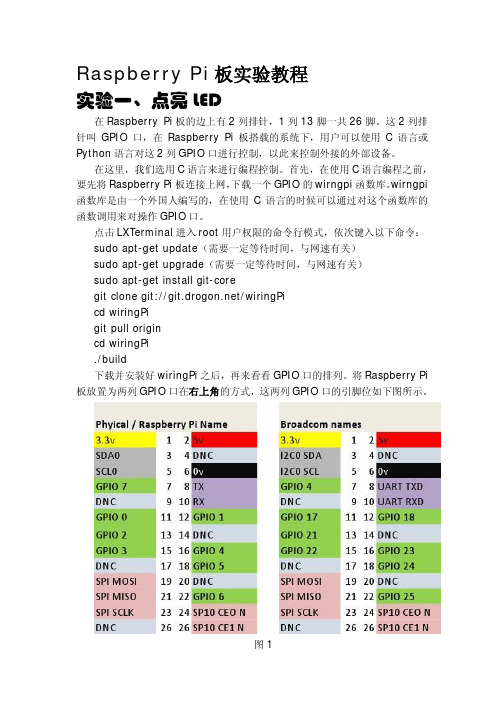
将Raspberry Pi 板放置为两列GPIO口在右上角的方式,这两列GPIO口的引脚位如下图所示。
图1图1右边的这张图,就是GPIO的实际引脚位。
而左边的图则是wirngpi 库定义的引脚位图。
编程的时候,只需要以左图为标准就可以了,不需要理会右图。
现在,我们要使用GPIO口来控制LED的亮灭。
LED就是发光二极管,这里需要一块外接的电路板。
如下图:图2这块板的电路图如下:图3这块板是用来驱动步进电机转动的,板子上有4个发光二极管分别接在ULN2003的四个输出上。
将这板连接到Raspberry Pi板上就可以通过操作Raspberry Pi板的GPIO来控制电机板上的发光二级管。
用杜邦线将Raspberry Pi板和电机板连接起来,如果只是简单的控制上面的1个发光二极管,那么只需要连接三条线:电源线(VCC)、地线(GND)和一条IO线。
gpio的使用流程

GPIO的使用流程1. 概述GPIO(General Purpose Input/Output)是一种通用输入/输出接口,用于连接外部设备与嵌入式系统进行通信。
在嵌入式系统中,通常通过GPIO来控制各种外部设备,如LED灯、蜂鸣器、传感器等。
2. 硬件准备在使用GPIO之前,需要准备以下硬件设备: - 嵌入式开发板:通常是一块单片机或开发板,如Arduino、Raspberry Pi等。
- 外部设备:如LED灯、蜂鸣器、传感器等。
- 连接线:用于连接嵌入式开发板和外部设备。
3. GPIO的基本原理GPIO的基本原理是通过改变管脚的电平(高电平或低电平)来控制外部设备。
一般情况下,将管脚设置为高电平,外部设备会被打开或激活,将管脚设置为低电平,外部设备会被关闭或停止。
4. GPIO的使用步骤使用GPIO的基本步骤如下:步骤1:引入相关库文件在开始使用GPIO之前,需要引入相关的库文件或头文件。
具体的引入方法会根据不同的嵌入式开发板而有所不同。
可以通过以下命令来引入GPIO库文件:import gpio步骤2:初始化GPIO在使用GPIO之前,需要将GPIO管脚初始化为输入或输出模式。
可以使用以下命令来初始化GPIO管脚:gpio.setup(pin, mode)其中,pin是GPIO管脚的编号,mode是管脚的模式,可以设置为输入或输出。
步骤3:读取或设置GPIO管脚的值•读取GPIO管脚的值:使用以下命令来读取GPIO管脚的值:value = gpio.input(pin)其中,pin是GPIO管脚的编号,value是GPIO管脚的值,可以是高电平或低电平。
•设置GPIO管脚的值:使用以下命令来设置GPIO管脚的值:gpio.output(pin, value)其中,pin是GPIO管脚的编号,value是GPIO管脚的值,可以设置为高电平或低电平。
步骤4:清理GPIO在使用完GPIO之后,可以使用以下命令来清理GPIO:gpio.cleanup()这个命令会将GPIO管脚恢复到初始状态。
树莓派的入门配置

树莓派新版-入门配置来源:网络 ?? 编辑:admin如果你有密集恐惧症则只需要看标题和字体加粗部分.有下划线的是网站都可以点开的.Linux系统分支有很多国内常用的分支主要是:1.Debian2.Redhat参考:GNU/Linux发行版历年分支进化图一览.目前桌面版Debian分支相比要做的好点,服务器端肯定是Redhat分支了,因为树莓派硬件是基于ARM的,所以在树莓派官网也有针对其的编译版.RASPBIAN 对应debianPIDORA 对应 Redhat下的Fedora分支好了废话不多说,正文开始.1.系统安装写入SD卡a)在官网下载?RASPBIAN?的镜像,点击前面的链接下载,最新版本有900多M,下载后解压文件.b)这里推荐使用Win32DiskImager这款软件来将树莓派系统写入到SD卡c)然后将SD卡插入树莓派,并且连接上网线和电源.2.使用 raspi-config工具配置树莓派a)查看ip正常情况下树莓派就可以启动了,但是现在还不知道他的IP,无法用ssh的方式进入系统,如果会用路由器查看ip的朋友就不是事,如果不会的可以使用Advanced IP scanner这款软件查看.b)系统配置知道IP了就可以进入系统配置了树莓派的默认账号是pi,默认密码是raspberry.SSH进入后输入?sudo raspi-config这个命令会弹出这个命令行配置界面1 Expand Filesystem扩展文件系统按回车即可.(将SD卡利用率最大化).2 Change User Password?改变默认pi用户的密码.3 Enable Boot to Desktop/Scratch启动时进入的环境选择? Console Text console, requiring login(default)? 启动时进入字符控制台,需要进行登录(默认项)? Desktop log in as user "pi" at the graphical desktop? 启动时进入LXDE图形界面的桌面? Scratch Start the Scratch programming environment upon boot? 启动时进入Scratch编程环境,进入后,可以点File->Exit退出,然后在退出过程中按Ctrl+C进入控制台。
gpioset gpioget用法

GPIO(General Purpose Input/Output)是一种通用输入输出接口,可以用于连接不同外部设备,如传感器、执行器、LED等。
在嵌入式系统中,我们经常需要使用GPIO来控制外部设备的状态,这就需要使用一些工具来对GPIO进行设置和获取。
在Linux系统中,我们可以使用gpioset和gpioget这两个命令来实现对GPIO的设置和获取。
本文将介绍gpioset和gpioget的用法及相关注意事项。
一、gpioset的用法gpioset命令用于设置GPIO的状态,可以将GPIO设置为高电平、低电平或者反转电平。
其基本用法如下:1. 设置GPIO为高电平:gpioset <chip设备编号> <引脚编号>=12. 设置GPIO为低电平:gpioset <chip设备编号> <引脚编号>=03. 反转GPIO电平:gpioset <chip设备编号> <引脚编号>=2其中,<chip设备编号>为GPIO设备在系统中的编号,<引脚编号>为具体引脚的编号。
通过这些简单的命令,我们可以轻松地控制GPIO 的状态。
需要注意的是,使用gpioset命令设置GPIO状态时,需要保证所选的GPIO引脚是可编程的,并且拥有足够的权限。
否则,可能会出现权限不足的错误,导致操作失败。
二、gpioget的用法gpioget命令用于获取GPIO的状态,可以用来查看某个特定GPIO引脚当前的状态(高电平或低电平)。
其基本用法如下:1. 获取GPIO状态:gpioget <chip设备编号> <引脚编号>通过这个命令,我们可以查看指定GPIO引脚的当前状态,并据此进行相应的处理。
同样地,使用gpioget命令时也需要注意设备编号和引脚编号的选择,以及对GPIO的访问权限。
三、常见问题及解决方法在使用gpioset和gpioget命令时,可能会遇到一些常见的问题,下面进行逐一介绍及解决方法。
ORANGES操作系统编写OS层次的IO程序

ORANGES操作系统编写OS层次的IO程序在ORANGES操作系统中,I/O(Input/Output)程序是一个非常重要的部分,用于与计算机外部设备进行通信和数据交换。
在OS层次的I/O程序中,我们需要实现对外围设备的控制、数据传输和错误处理等功能。
本文将详细介绍在ORANGES操作系统中编写OS层次的I/O程序的步骤和技术要点。
一、I/O系统概述I/O系统是计算机系统中的一个重要部分,它负责将外部设备(如键盘、鼠标、打印机、硬盘等)与计算机的中央处理器进行连接和通信。
在ORANGES操作系统中,I/O系统包括了多个组件,如设备驱动程序、设备控制器、中断处理程序、缓冲管理等。
设备驱动程序是I/O系统的重要组成部分,它是连接外部设备和操作系统之间的桥梁。
设备驱动程序负责根据设备的特性和工作方式,实现对设备的控制和数据传输。
设备控制器是硬件设备,负责控制外部设备的工作状态和数据传输。
中断处理程序则是在外部设备向CPU发送中断信号时,负责处理中断请求,通知操作系统进行相应的处理。
二、I/O程序的编写步骤1.设备驱动程序的编写:设备驱动程序是I/O系统的核心组件,它负责将外部设备的接口和工作方式翻译成操作系统可以理解的指令和数据格式。
在ORANGES操作系统中,设备驱动程序通常以设备接口的形式实现,通过调用设备的控制命令和数据传输函数,实现对设备的控制和数据交换。
2.设备控制器的初始化:在编写I/O程序时,需要先初始化设备控制器,使其处于正常工作状态。
设备控制器的初始化包括设备的硬件参数配置、中断处理程序的注册、设备缓冲区的创建等操作。
3.中断处理程序的编写:中断处理程序是在外部设备向CPU发送中断信号时,负责处理中断请求和通知操作系统进行相应的处理。
在ORANGES操作系统中,中断处理程序通常以中断向量的形式实现,将中断请求映射到相应的中断处理函数,进行相应的处理。
4.缓冲管理的实现:在I/O数据传输过程中,需要使用缓冲区来存储数据。
gpio编程说明 -回复

gpio编程说明-回复GPIO编程是指通过控制树莓派(Raspberry Pi)的通用输入输出端口(GPIO)来实现与外部设备(如传感器、执行器等)的交互。
在树莓派上进行GPIO编程可以让我们通过程序控制硬件,从而实现各种功能,如控制LED灯、读取按钮输入、采集环境数据等。
本文将以中括号内的内容为主题,详细介绍GPIO编程的基本概念、使用方法和注意事项。
一、基本概念1. GPIO引脚GPIO引脚是树莓派上可编程的数字输入输出引脚。
树莓派一般有多个GPIO引脚可供使用,每个引脚都可以通过程序来配置和控制。
GPIO引脚既可以作为输入接口接收外部信号,也可以作为输出接口输出电平信号。
2. 控制IO口电平GPIO引脚的电平即为其上的电压状态,一般有高电平和低电平两种状态。
高电平一般表示为1,低电平一般表示为0。
通过控制GPIO引脚的电平状态可以实现与外部设备的通信和交互。
3. 电平转换电路在实际应用中,外部设备的电平状态和树莓派的GPIO引脚的电平状态可能不一致,因此需要通过电平转换电路来匹配两者之间的电平差异。
常用的电平转换电路有电阻分压电路和三极管电路等,具体根据应用需求选择适当的电平转换电路。
二、GPIO编程方法在树莓派上进行GPIO编程主要有两种方法,一种是使用系统的IO库,如wiringPi库,另一种是使用Python语言的RPi.GPIO库。
下面将详细介绍这两种方法的使用。
1. 使用wiringPi库进行GPIO编程wiringPi是一款广泛应用的树莓派GPIO编程库,提供了丰富的API函数,简化了GPIO的配置和控制过程。
使用wiringPi库,需要先在树莓派上安装该库,然后在程序中包含相关头文件,并链接库文件,最后进行GPIO 的配置和控制操作。
2. 使用RPi.GPIO库进行GPIO编程RPi.GPIO是树莓派上广泛使用的Python GPIO编程库,使用该库可以简便地在Python语言下进行GPIO编程。
Raspberry Pi与Node-RED和工业GPIO构建教程(第1页)技术说明单表单2213-1

Build a Raspberry Pi with Node-RED and Industrial GPIO PAGE1TECHNICAL NOTEForm 2213-170123Build a Raspberry Pi with Node-RED and Industrial GPIOIntroductionNOTE: This technical note was originally a blog post on . We’ve reproduced theblog post here for your convenience.The Raspberry Pi® is an unquestionably powerful computer for just $35. And it really isjust that: a computer. That means the Pi is capable of many tasks and perfect for manyautomation applications.Couple the Pi to industrial, solid-state digital inputs and outputs , and you can buildcompelling and cost-effective solutions for commercial and industrial applications, too.One of the easiest and fun ways to quickly build software applications is with Node-RED ,the free, open-source software tool designed by IBM® Emerging Technologies and usedfor wiring together hardware devices, APIs, and online services in new and interestingways.However, Node-RED is only included in the full PIXEL GUI version of the Raspbian JessieOperating System, available from . Their latest2016-11-25-raspbian-jessie-lite.img build for headless operation (no monitor, keyboard,or mouse required) is no longer bundled with either Node-RED or the required softwaretools node.js and npm.The purpose of this post is to guide you through creating a headless Raspberry Picomputer with the latest versions of Node-RED, node.js, and npm, building a Node-REDapplication, and controlling and sensing GPIO connected to industrial digital I/O, quicklyand simply. This example uses the Opto 22 Digital I/O for Raspberry Pi Starter Kit.Build a Raspberry Pi with Node-RED and Industrial GPIO 2TECHNICAL NOTE •Form 2213-170123This post provides step-by-step instructions for:•Building and configuring your microSD boot image with Raspbian Jessie Lite •Installing Node-RED, node.js, and npm •Configuring Node-RED to start up at boot time •Installing various Node-RED nodes, including our SNAP PAC Node-RED nodes (optional)•Importing a Node-RED flow for sensing and controlling digital I/O through GPIO nodesHere is a diagram of the steps you'll take:What you'll need:•A Raspberry Pi—I'm using a Raspberry Pi 3•A microSD card (minimum 8 GB) and reader for your computer •A power supply Optional items used in this post (needed to see the result of a Node-RED flow with GPIO nodes):• A Digital I/O for Raspberry Pi Starter Kit —includes carrier board, rack, and four I/O modules Now, I'm no expert with the Raspberry Pi or the Linux command line. You don't need to be,either. I think you'll find the following instructions pretty easy to do if you're careful to follow thesteps in order.When you're done, you'll have yourself a complete, powerful, and exciting computing platformto build the automation application of your dreams.Build a Raspberry Pi with Node-RED and Industrial GPIO 3TECHNICAL NOTE •Form 2213-170123Step 1: Build and Configure Raspbian microSD boot device1.Download Raspbian Jessie Lite image for headless operation (no monitor, keyboard, ormouse needed): https:///raspbian_lite_latest2.Unzip the file into your /Downloads folder.Instructions for OS X from Terminal window:diskutil listDetermine microSD disk name from result (for example, for disk4):diskutil unmount disk4s1cd downloads/Choose one (1st for Jessie; 2nd for Jessie Lite):sudo dd bs=1m if=2016-11-25-raspbian-jessie.img of=/dev/rdisk4sudo dd bs=1m if=2016-11-25-raspbian-jessie-lite.imgof=/dev/rdisk4Instructions for Windows:–Download Win32 Disk Imager: https:///projects/win32diskimager/–Install and start Win32 Disk Imager.–Select image file from your Downloads folder, and choose the drive letter for your SDcard.–Click Write.UPDATE: The latest Raspbian Jessie image from (016-11-25-raspbian-jessie-lite.img)no longer allows SSH connections by default. You must place a file with no extension named "ssh" inthe root of the card. To do this, simply create a new Text Document on your desktop with no contents,then rename the file to remove the extension. Copy this file onto your microSD card in the /BOOT/directory. Now, you can SSH in as shown in the next step.Step 2: Log in and Configure Headless PiWe’re using the command prompt method for headless operation under Jessie LiteNOTE: this step could be problematic if more than one Raspberry Pi3/Raspbian Jessie in its defaultconfiguration exists on your network or if your DNS cache isn't flushed. If your connection is refused,see update in previous step.1.Log in:Mac/Linux: Attempt SSH session from your terminal application:ssh pi@raspberrypiWindows: You'll need the free PuTTy terminal application download. Once installed, enterraspberrypi in the Host Name (or IP address) field. Make sure the port number is 22 andSSH option is selected, then click Open.Build a Raspberry Pi with Node-RED and Industrial GPIO2.Once connected, log in:Mac/Linux: pi@raspberrypi’s password: raspberryWindows: login as: pipi@raspberrypi’s password: raspberry3.At the command prompt, enter: sudo raspi-config4.Select Option 1 - Expand Filesystem5.Select Option 2 - Change User Password (for example, opto22)6.Select Option 9 - Advanced Options; select option A2 - Change Hostname (example:rpi-g4pb8h-benson)7.Select Option 5 - Internationalisation Options (example for user in California):Locales: en_US.UTF-8 UTF-8Timezone: US, Pacific OceanChange Wi-Fi Country: US (press “U” to get close)8.Select <Finish> and then select yes when prompted for reboot.9.Log back in with new Hostname (example: ssh pi@rpi-g4pb8h-benson).10.Enter your new password.Step 3: Install Node.js, npm, and Node-REDsudo su -curl -sL https:///setup_6.x | sudo bash -apt-get install nodejs -ynode -v (returns v6.9.2 or higher)npm -v (returns 3.10.9 or higher)npm cache cleannpm install -g --unsafe-perm node-redexitnode-redAt this point, confirm that Node-RED is running by navigating with your browser to your Pi andport 1880:http://[hostname]:1880 (example: http://rpi-g4ph8h-benson:1880)Step 4: Build your first Node-RED appNote: This step and the next exercise are important for two reasons: (1) They confirm thateverything is installed properly; and (2) They create the appropriate folders for the remainingsteps.1.Click and drag an Inject node to the palette.2.Drag a Debug node to the palette.4TECHNICAL NOTE•Form 2213-170123Build a Raspberry Pi with Node-RED and Industrial GPIO 5TECHNICAL NOTE •Form 2213-1701233.Wire the two nodes together.4.Click Deploy in the upper-right corner of Node-RED.5.Click the Debug tab beneath the Deploy button.6.Finally, click the tab emerging from the left of the Inject node. You should see the currenttime (in Epoch time) in the debug pane.Now go back to your terminal session, and issue the following command:ctrl-c (to shut down Node-RED)sudo shutdown -P nowThis final command immediately shuts down your Pi with the Poweroff parameter, finishes disk writes, and requires you to remove and reinstall power to boot back up again. This is a safetymeasure to make sure all of your work up to this point is saved to the microSD card. Always wait for the green LED on the Pi to go out completely before removing power.NOTE: I highly recommend always using the shutdown command to preserve your Pi file system if you intend to power down the system. If you'd rather just reboot the Pi, use:sudo shutdown -r nowStep 5: Install SNAP PAC Node-RED Nodes (optional)The SNAP PAC Node-RED nodes offer a simple method for querying and controlling a SNAP PAC I/O System. You can use a SNAP PAC I/O system to gather and control analog, serial, and other digital I/O data not covered by any G4 and SNAP digital I/O connected to the GPIO of the Pi.NOTE: If you’ve installed Node-RED on your existing Pi separately from the above instructions, be sure you have node.js version 4.4.5 or later installed first. This is the minimum supported version to useOpto 22’s SNAP PAC Node-RED nodes. You can determine node’s version with the followingcommand: node -vpwd (should result in /home/pi)cd .node-rednpm install node-red-contrib-pacStep 6: Set up Node-RED to start up at bootThe Node-RED recommended method is to install Node-RED Service:sudo su -wgethttps:///node-red/raspbian-deb-package/master /resources/nodered.service -O /lib/systemd/system/nodered.servicewgethttps:///node-red/raspbian-deb-package/master /resources/node-red-start -O /usr/bin/node-red-startBuild a Raspberry Pi with Node-RED and Industrial GPIO 6TECHNICAL NOTE •Form 2213-170123wgethttps:///node-red/raspbian-deb-package/master /resources/node-red-stop -O /usr/bin/node-red-stopchmod +x /usr/bin/node-red-st*systemctl daemon-reloadsystemctl enable nodered.serviceshutdown -r nowWhen the Pi reboots, Node-RED should be running. Access the Node-RED environment fromyour web browser here:http://[hostname]:1880 (for example, http://rpi-g4pb8h-benson:1880)When installing new nodes from the command line, start/stop Node-RED by using theNode-RED service commands:node-red-stopnode-red-startStep 7: Import a GPIO-based Node-RED flow to test I/OThis final step involves importing a Node-RED flow I've created to test the GPIO nodes and the corresponding I/O modules on the rack. (This test flow will work either with or without the rack and I/O modules.)Power up your Pi, and log into Node-RED. Then we'll import this flow:To import this flow, go to your Node-RED application (http://[hostname]:1880), click the hamburger icon in the top right, select "Import", then "Clipboard" and choose the New Flowbutton. Next, copy and paste this code into the resulting window:[{"id":"d95eb067.d4687","type":"inject","z":"aa9ee7c0.e8cd88","name":"Turn OnOutput","topic":"0","payload":"","payloadType":"num","repeat":"","cron tab":"","once":false,"x":300,"y":180,"wires":[["878648ac.fc2948"]]},{"id":"878648ac.fc2948","type":"rpi-gpioout","z":"aa9ee7c0.e8cd88","name":"G4ODC5 digital output in position3","pin":"35","set":"","level":"0","out":"out","x":660,"y":220,"wires":[]},{"id":"7d18b79f.0fa588","type":"inject","z":"aa9ee7c0.e8cd88","naBuild a Raspberry Pi with Node-RED and Industrial GPIO 7TECHNICAL NOTE •Form 2213-170123me":"Turn OffOutput","topic":"","payload":"1","payloadType":"num","repeat":"","cron tab":"","once":false,"x":300,"y":260,"wires":[["878648ac.fc2948"]]},{"id":"82511eef.33cbb","type":"rpi-gpioin","z":"aa9ee7c0.e8cd88","name":"G4IDC5MA module in position0","pin":"40","intype":"tri","debounce":"25","read":false,"x":330,"y":400,"wires":[["6f379125.5007d","878648ac.fc2948"]]},{"id":"6f379125.5007d","type":"debug","z":"aa9ee7c0.e8cd88","name":"Status ofG4IDC5MA","active":true,"console":"false","complete":"payload","x":620,"y":400,"wires":[]},{"id":"2e694694.1487aa","type":"comment","z":"aa9ee7c0.e8cd88","name":"Make sure G4ODC5MA is in Automode","info":"","x":652.5,"y":146,"wires":[]}]Finally, click Import. Now, position the nodes on the canvas where you like, and you're done. Click the Deploy button to deploy this flow to your Pi.Now, you can click the left side of the Inject button named "Turn On Output" and you should see the value under the node named "G4ODC5 digital output in position 3" change to "0". Click the Inject button named "Turn Off Output", and the value will change to one.If this result seems inverted to you, it's because Opto 22 solid-state I/O modules are negative-true logic: Write a 0 to turn on; write a 1 to turn off.To see this in live action, I've used the new Digital I/O for Raspberry Pi Starter Kit (available for a limited time at $99). I placed my own Raspberry Pi3 (I purchased mine at ) on the assembled Starter Kit atop the OPTO-P1-40P carrier board and attached that to the G4PB8H mounting rack. Then, I inserted each of the 4 modules in the orientation shown in the photo on page 1. That puts my DC input module (G4IDC5MA ) in position 0 on the rack, and the DC output module (G4ODC5) in position 3.I connected the system to an Ethernet network, and powered it up using my Pi power supply (wall wart).Note that this test flow will work without the rack and I/O modules. You just won't be able to see the LEDs positively indicate everything is working properly. In the blog post you can see a short video I took with my phone, showing what happens on the rack when I flip the switch on the input, and the resulting output module firing.If you have the Starter Kit and followed all of the instructions above, you can turn the G4ODC5 on and off from software (Node-RED). Simply click the Inject button on the left of the nodes labeled Turn On Output and Turn Off Output.All done!Congratulations! You've just built a fully configured, latest-build Raspberry Pi computer with Node-RED and the ability to interface with real-world electrical loads using the Pi's GPIO pins.Let me know how your installation went in the comments section of the blog . I'd also love to hear any tips, comments, suggestions, or complaints, too!Thanks for reading. See the next page for additional nodes you may want to install.Build a Raspberry Pi with Node-RED and Industrial GPIOBONUS: Other nodes you may find usefulThere are hundreds of Node-RED nodes available from npm and . Here are afew I’ve found useful for various tasks. There are two ways to install these nodes.The preferred method is from within Node-RED. From the hamburger menu at the top right,select Manage Palette. Then click the Install tab in the left pane. You can search by the name ofthe node listed below, and click the small Install button.If you prefer, you can also install from the command line. Use these steps:1.Establish an SSH session to your RPi.2.Navigate to your .node-red folder (usually found under /home/pi folder):cd .node-redBigtimer—timer with dusk, dawn, months, days, manual override, schedule pause, and morenpm install node-red-contrib-bigtimerPing—for taking input and pinging devices on a networknpm install node-red-configurable-pingMSSQL—for establishing a connection to a Microsoft SQL Server instance, locally or in thecloud.npm install node-red-contrib-mssqlMySQL—for connecting to and exchanging data with MySQL databasesnpm install node-red-node-mysqlM2X—for connecting to and interfacing with AT&T’s M2X IoT Platformnpm install node-red-m2xBluemix—various nodes for interfacing with theIBM Bluemix® IoT platformnpm install node-red-bluemix-nodesAggregator—for aggregating numeric values over a specific time span, including mean,median, min, maxnpm install node-red-contrib-aggregatorMoment—produces a nicely formatted Date/Time stringnpm install node-red-contrib-momentSNMP—for fetching either individual oids, or a table oid from an SNMP-enabled hostnpm install node-red-node-snmpWeather Underground—for getting the current weather conditions and forecastnpm install node-red-node-weather-undergroundDropbox—to send and receive files from Dropbox cloudnpm install node-red-node-dropboxModbus TCP—to communicate with Modbus/TCP devices over Ethernet.npm install node-red-contrib-modbus8TECHNICAL NOTE•Form 2213-170123Build a Raspberry Pi with Node-RED and Industrial GPIOForm 2213-170123 • Opto 22 • 43044 Business Park Drive • Temecula, CA 92590-3614 • SALES800-321-6786•951-695-3000•FAX951-695-3095•****************•SUPPORT800-835-6786•951-695-3080•FAX951-695-3017•******************© 2017 Opto 22. All rights reserved. Dimensions and specifications are subject to change. Brand or product names used herein are trademarks or registered trademarks of their respective companies or organizations.9Sparkplug—to communicate with Cirrus Link or Ignition MQTT servers with Sparkplug protocolnpm install node-red-contrib-sparkplugTo install all these nodes at once:cd .node-rednode-red-stopnpm install node-red-contrib-bigtimer node-red-configurable-ping node-red-contrib-mssql node-red-node-mysql node-red-m2xnode-red-bluemix-nodes node-red-contrib-moment node-red-node-snmp node-red-node-weather-underground node-red-node-dropboxnode-red-contrib-modbus node-red-contrib-sparkplugnode-red-start。
树莓派编程实例

树莓派编程实例
在树莓派上进行编程可以非常有趣和有用。
这里有一个简单的实例,可以让你了解如何使用Python语言在树莓派上编写程序并控制LED灯闪烁。
使用的材料:
- 树莓派
- 一块面包板
- 一些杜邦线
- 一块LED灯
- 一个100Ω的电阻
步骤:
1. 首先在面包板上插入LED灯和100Ω电阻,将它们连接好。
2. 将LED灯的正极连接至树莓派的GPIO 17号引脚上,负极连接至GND引脚上。
3. 打开树莓派的终端,进入Python编程环境。
4. 输入以下Python代码:
```
import RPi.GPIO as GPIO
import time
GPIO.setmode(GPIO.BCM)
GPIO.setup(17, GPIO.OUT)
while True:
GPIO.output(17, GPIO.HIGH)
time.sleep(1)
GPIO.output(17, GPIO.LOW)
time.sleep(1)
```
5. 运行上述代码后,LED灯就会开始闪烁。
以上就是一个简单的树莓派编程实例,通过控制GPIO输出高低电平,实现了对LED灯的控制。
当然,在实际的应用中,我们可以通过编写更复杂的代码,结合传感器、摄像头等硬件设备,来实现更丰富、更有趣的功能。
树莓派GPIO操作.1(Python版本)

树莓派GPIO操作.1(Python版本)今天的最后一篇文章,一共7篇,很久没有写这么满了。
后面的硬件就不测试了,大概率是正确的,我只写源代码。
而且这些代码放在Jetson Nano上面也是可以的。
源码都是主机上面写的,环境是Python3.7:如图所示先安装urllib3,我以前写爬虫是2安装一些插件,教我做人•https:///语言模式,就写Python••••import urllibcontens = urllib.urlopen("/").read()print(contens)出错了•••from urllib.request import urlopenwebpage = urlopen('')print(webpage)这个还算靠谱••••import sys for(i, value) in enumerate(sys.argv): print("arg:%d %s" % (i, value))这是它的第一种用法,直接读取命令行的数组•python.exe .\url.py a b c d也可以这样执行后面是捕获的参数树莓派B+另一个引脚图•https:///project/RPi.GPIO/•https:///zhongzhi107/raspberry-pi-tutorials•https:///p/raspberry-gpio-python/code/ci/default/tree/源文件是C的,应该是包装了Python的接口C文件py_gpio.py看上去都是C的实现,包装了一个接口这样只能尽可能的快了,差不多够用吧使用的方法是BCM•••••••••••import RPi.GPIO as GPIOimport timeGPIO.setmode(GPIO.BCM)GPIO.setup(18, GPIO.OUT)while (True): GPIO.output(18, True) time.sleep(0.5) GPIO.output(18, False) time.sleep(0.5)LED闪烁的程序用到了io和time,先设置IO的map方式,然后是引脚。
全志H3香橙派OrangePiLite开发板40Pin的GPIO口测试

全志H3香橙派OrangePiLite开发板40Pin的GPIO口测试
wiringOP安装
wiringOP 已适配 Orange Pi 开发板,使用 wiringOP 可以测试GPIO,开始测试前,请确保已经安装好了 wiringOP
普通 GPIO 口测试
1) 下面以 7 号引脚——对应 GPIO 为 PA6 ——对应 wPi 序号为2——为例演示如何设置 GPIO 的高低电平
2) 首先设置GPIO 口为输出模式,其中第三个参数需要输入引脚对应的 wPi 的序号
3) 然后设置GPIO 口输出低电平,设置完后可以使用万用表测量引脚的电压的数值,如果为 0v,说明设置低电平成功
4) 然后设置GPIO 口输出高电平,设置完后可以使用万用表测量引脚的电压的数值,如果为 3.3v,说明设置高电平成功。
香橙派OrangePi3开发板在Linux系统下修改Framebuffer宽度和高度的方法

香橙派OrangePi3开发板在Linux系统下修改Framebuffer
宽度和高度的方法
注意:此方法只适用于linux4.9 内核的系统,linux5.4 内核的系统无法使用
1) 在linux 系统的/boot/orangepiEnv.txt 中有fb0_width 和fb0_height 两个变量,可以通过它们来设置Framebuffer 的宽度和高度,linux 系统默认设置 fb0_width=1280、 fb0_height=720
2) fb0_width 和 fb0_height 不同分辨率对应的参考值如下所示
3) 在相同的 HDMI 分辨下,不同的 fb0_width 和 fb0_height 的显示情况如下所示,当 fb0_width 和 fb0_height 设置的值越大时,屏幕显示的文字就越小,当fb0_width 和fb0_height 设置的值越小时,屏幕显示的文字就越大
a. HDMI 分辨率为1080p60,fb0_width 和fb0_height 为1920x1080 的显示情况
b. HDMI 分辨率为1080p60,fb0_width 和fb0_height 为1280x720 的显示情况
c. HDMI 分辨率为1080p60,fb0_width 和fb0_height 为720x576 的显示情况
d. HDMI 分辨率为1080p60,fb0_width 和fb0_height 为720x480 的显示情况。
- 1、下载文档前请自行甄别文档内容的完整性,平台不提供额外的编辑、内容补充、找答案等附加服务。
- 2、"仅部分预览"的文档,不可在线预览部分如存在完整性等问题,可反馈申请退款(可完整预览的文档不适用该条件!)。
- 3、如文档侵犯您的权益,请联系客服反馈,我们会尽快为您处理(人工客服工作时间:9:00-18:30)。
Orange PI GPIO控制详细教程一、sysfs方式通过sysfs方式控制GPIO,先访问/sys/class/gpio目录,向export文件写入GPIO编号,使得该GPIO的操作接口从内核空间暴露到用户空间,GPIO的操作接口包括direction和value 等,direction控制GPIO方向,而value可控制GPIO输出或获得GPIO输入。
文件IO方式操作GPIO,使用到了4个函数open、close、read、write。
首先,看看系统中有没有“/sys/class/gpio”这个文件夹。
如果没有请在编译内核的时候加入Device Drivers-> GPIO Support ->/sys/class/gpio/…(sysfs interface)。
/sys/class/gpio 的使用说明:gpio_operation 通过/sys/文件接口操作IO端口GPIO到文件系统的映射◇控制GPIO的目录位于/sys/class/gpio◇/sys/class/gpio/export文件用于通知系统需要导出控制的GPIO引脚编号◇/sys/class/gpio/unexport 用于通知系统取消导出◇/sys/class/gpio/gpiochipX目录保存系统中GPIO寄存器的信息,包括每个寄存器控制引脚的起始编号base,寄存器名称,引脚总数导出一个引脚的操作步骤◇首先计算此引脚编号,引脚编号= 控制引脚的寄存器基数+ 控制引脚寄存器位数◇向/sys/class/gpio/export写入此编号,比如12号引脚,在shell中可以通过以下命令实现,命令成功后生成/sys/class/gpio/gpio12目录,如果没有出现相应的目录,说明此引脚不可导出◇direction文件,定义输入输入方向,可以通过下面命令定义为输出。
direction接受的参数:in, out, high, low。
high/low同时设置方向为输出,并将value设置为相应的1/0◇value文件是端口的数值,为1或0几个例子:1. 导出/sys/class/gpio# echo 44 > export2. 设置方向/sys/class/gpio/gpio44# echo out > direction3. 查看方向/sys/class/gpio/gpio44# cat direction4. 设置输出/sys/class/gpio/gpio44# echo 1 > value5. 查看输出值/sys/class/gpio/gpio44# cat value6. 取消导出/sys/class/gpio# echo 44 > unexport二、文件读写例程#include stdlib.h#include stdio.h#include string.h#include unistd.h#include fcntl.h /* define O_WRONLY and O_RDONLY *//* 芯片复位引脚: P1_16 */#define SYSFS_GPIO_EXPORT "/sys/class/gpio/export"#define SYSFS_GPIO_RST_PIN_VAL "48"#define SYSFS_GPIO_RST_DIR "/sys/class/gpio/gpio48/direction"#define SYSFS_GPIO_RST_DIR_VAL "OUT"#define SYSFS_GPIO_RST_VAL "/sys/class/gpio/gpio48/value"#define SYSFS_GPIO_RST_VAL_H "1"#define SYSFS_GPIO_RST_VAL_L "0"int main(){int fd;/* 打开端口/sys/class/gpio# echo 48 > export */fd = open( SYSFS_GPIO_EXPORT, O_WRONLY );if ( fd == -1 ){printf( "ERR: Radio hard reset pin open error.\n" );return(EXIT_FAILURE);}write( fd, SYSFS_GPIO_RST_PIN_VAL, sizeof(SYSFS_GPIO_RST_PIN_VAL) );close( fd );/* 设置端口方向/sys/class/gpio/gpio48# echo out > direction */fd = open( SYSFS_GPIO_RST_DIR, O_WRONLY );if ( fd == -1 ){printf( "ERR: Radio hard reset pin direction open error.\n" );return(EXIT_FAILURE);}write( fd, SYSFS_GPIO_RST_DIR_VAL, sizeof(SYSFS_GPIO_RST_DIR_VAL) );close( fd );/* 输出复位信号: 拉高>100ns */fd = open( SYSFS_GPIO_RST_VAL, O_RDWR );if ( fd == -1 ){printf( "ERR: Radio hard reset pin value open error.\n" );return(EXIT_FAILURE);}while ( 1 ){write( fd, SYSFS_GPIO_RST_VAL_H, sizeof(SYSFS_GPIO_RST_VAL_H) );usleep( 1000000 );write( fd, SYSFS_GPIO_RST_VAL_L, sizeof(SYSFS_GPIO_RST_VAL_L) );usleep( 1000000 );}close( fd );printf( "INFO: Radio hard reset pin value open error.\n" );return(0);}三、中断检测#include stdlib.h#include stdio.h#include string.h#include unistd.h#include fcntl.h#include poll.h#define MSG( args ... ) printf( args )/* 函数声明 */static int gpio_export( int pin );static int gpio_unexport( int pin );static int gpio_direction( int pin, int dir );static int gpio_write( int pin, int value );static int gpio_read( int pin );static int gpio_export( int pin ){char b uffer[64];int len;int fd;fd = open( "/sys/class/gpio/export", O_WRONLY );if ( fd < 0 ){MSG( "Failed to open export for writing!\n" );return(-1);}len = snprintf( buffer, sizeof(buffer), "%d", pin );if ( write( fd, buffer, len ) < 0 ){MSG( "Failed to export gpio!" );return(-1);}close( fd );return(0);}static int gpio_unexport( int pin ){char b uffer[64];int len;int fd;fd = open( "/sys/class/gpio/unexport", O_WRONLY );if ( fd < 0 ){MSG( "Failed to open unexport for writing!\n" );return(-1);}len = snprintf( buffer, sizeof(buffer), "%d", pin );if ( write( fd, buffer, len ) < 0 ){MSG( "Failed to unexport gpio!" );return(-1);}close( fd );return(0);}/* dir: 0-->IN, 1-->OUT */static int gpio_direction( int pin, int dir ){static const char dir_str[] = "in\0out";char path[64];int fd;snprintf( path, sizeof(path), "/sys/class/gpio/gpio%d/direction", pin );fd = open( path, O_WRONLY );if ( fd < 0 ){MSG( "Failed to open gpio direction for writing!\n" );return(-1);}if ( write( fd, &dir_str[dir == 0 ? 0 : 3], dir == 0 ? 2 : 3 ) < 0 ){MSG( "Failed to set direction!\n" );return(-1);}close( fd );return(0);}/* value: 0-->LOW, 1-->HIGH */static int gpio_write( int pin, int value ){static const char values_str[] = "01";char path[64];int fd;snprintf( path, sizeof(path), "/sys/class/gpio/gpio%d/value", pin );fd = open( path, O_WRONLY );if ( fd < 0 ){MSG( "Failed to open gpio value for writing!\n" );return(-1);}if ( write( fd, &values_str[value == 0 ? 0 : 1], 1 ) < 0 ){MSG( "Failed to write value!\n" );return(-1);}close( fd );return(0);}static int gpio_read( int pin ){char p ath[64];char v alue_str[3];int fd;snprintf( path, sizeof(path), "/sys/class/gpio/gpio%d/value", pin );fd = open( path, O_RDONLY );if ( fd < 0 ){MSG( "Failed to open gpio value for reading!\n" );return(-1);}if ( read( fd, value_str, 3 ) < 0 ){MSG( "Failed to read value!\n" );return(-1);}close( fd );return(atoi( value_str ) );}/** none表示引脚为输入,不是中断引脚* rising表示引脚为中断输入,上升沿触发* falling表示引脚为中断输入,下降沿触发* both表示引脚为中断输入,边沿触发* 0-->none, 1-->rising, 2-->falling, 3-->both*/static int gpio_edge( int pin, int edge ){const char dir_str[] = "none\0rising\0falling\0both";char ptr;char path[64];int fd;switch ( edge ){case 0:ptr = 0;break;case 1:ptr = 5;break;case 2:ptr = 12;break;case 3:ptr = 20;break;default:ptr = 0;}snprintf( path, sizeof(path), "/sys/class/gpio/gpio%d/edge", pin );fd = open( path, O_WRONLY );if ( fd < 0 ){MSG( "Failed to open gpio edge for writing!\n" );return(-1);}if ( write( fd, &dir_str[ptr], strlen( &dir_str[ptr] ) ) < 0 ){MSG( "Failed to set edge!\n" );return(-1);}close( fd );return(0);}/* GPIO1_17 */int main(){int gpio_fd, ret;struct pollfd fds[1];char buff[10];unsigned char cnt = 0;/* LED引脚初始化 */gpio_export( 115 );gpio_direction( 115, 1 );gpio_write( 115, 0 );/*按键引脚初始化 */gpio_export( 49 );gpio_direction( 49, 0 );gpio_edge( 49, 1 );gpio_fd = open( "/sys/class/gpio/gpio49/value", O_RDONLY );if ( gpio_fd < 0 ){MSG( "Failed to open value!\n" );return(-1);}fds[0].fd = gpio_fd;fds[0].events = POLLPRI;ret = read( gpio_fd, buff, 10 );if ( ret == -1 )MSG( "read\n" );while ( 1 ){ret = poll( fds, 1, 0 );if ( ret == -1 )MSG( "poll\n" );if ( fds[0].revents & POLLPRI ){ret = lseek( gpio_fd, 0, SEEK_SET );if ( ret == -1 )MSG( "lseek\n" );ret = read( gpio_fd, buff, 10 );if ( ret == -1 )MSG( "read\n" );gpio_write( 115, cnt++ % 2 );}usleep( 100000 );}return(0);}。
