光电转换器说明
光电切换器商品说明说明书
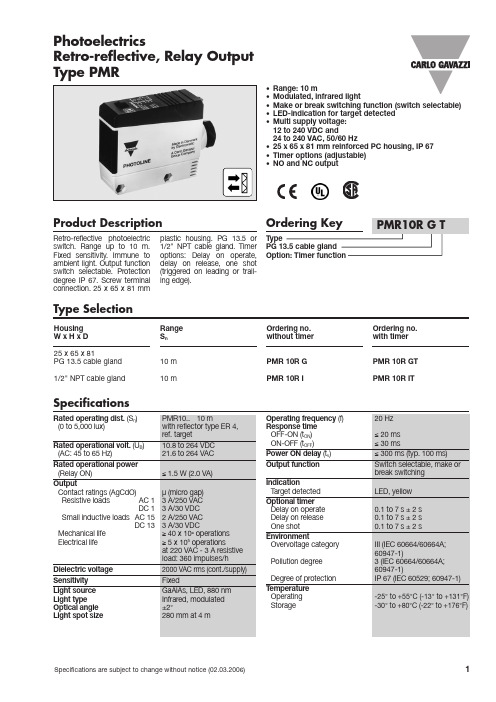
Optional timer Delay on operate Delay on release One shot
Environment Overvoltage category
Pollution degree
Degree of protection Temperature
Delivery Contents
• Photoelectric switch: PMR • Cable gland • Installation instruction • Mounting bracket • Packaging: Corrugated cardboard (environmentally
PMR 10R G PMR 10R I
Specifications
Rated operating dist. (Sn) (0 to 5,000 lux)
Rated operational volt. (UB) (AC: 45 to 65 Hz)
Rated operational power (Relay ON)
12 to 240 VDC and 24 to 240 VAC, 50/60 Hz • 25 x 65 x 81 mm reinforced PC housing, IP 67 • Timer options (adjustable) • NO and NC output
Product Description
110 g UL, CSA
Yes
Connection Diagram
Time adjustment (optional)
1 Break switching
2 Make switching
UT-2017说明书

RS-232/RS-485UT-2017无源光电隔离型接口转换器使用说明书UT-2017RS-232C RS-485RS-232RS-4852500Vrms RS-485TVS TRANSIENT VOLTAGE SUPPERSSOR TVS TVS LIGHTNING ESD 600W RS-485RS-232DB9RS-232C RS-485DB9I/O (RTS DTR )(RS-485)RS-232UT-201732RS-485300-19200BPS RS-232RS-485无源光电隔离型接口转换器、兼容、标准,能够将单端的信号转换为平衡差分的信号,内置的光电隔离器,能够提供高达的隔离电压,带有快速的瞬态电压抑制保护器,此保护器被设计用来保护接口,采用当今先进的()瞬态电压抑制器,正常情况下管呈高阻状态,当管两端经受瞬间的高能量冲击时,它能以极高的速度将其两端的阻抗降低,吸收一个大电流,从而把其两端的电压钳制在一个预定的数值上,保护后面的电路元件不因瞬态高压冲击而损坏。
此保护器可以有效地抑制闪电()和,提供每线的雷击浪涌保护功率,以及各种原因在线路上产生的浪涌电压和瞬态过压,并且极小的极间电容保证了接口的高速传输。
接口端通过一个母头的连接器与兼容标准接口相连,端通过公头为输出端。
转换器内部带有零延时自动收发转换,独有的电路自动控制数据流方向,而不需任何握手信号如、等,半双工模式转换,即插即用。
确保适合一切现有的通信软件和接口硬件,不需要对以前的基于的工作方式作任何软件的修改。
无源光电隔离型接口转换器可以为点到点、点到多点的通信提供可靠的连接,点到多点每台转换器可允许连接个接口设备,数据通讯速率,支持的通讯方式有到转换。
一、概述1EIA/TIA RS-232C RS-4852RS-232DB9RS-485DB93RS-232+/-15KVESD RS-485600W 、接口特性:接口兼容的、标准、电气接口:接口输入为母头连接器,接口输出为公头连接器、保护等级:接口保护,接口每线的浪涌保护雷击。
诺瓦科技LED发送卡光电转换器CVT4K-S规格书
CVT4K -S光电转换器产品 版本 : V1.0. 1 文档编号 :NS11 00 00432规格书版权所有©2018西安诺瓦电子科技有限公司。
保留一切权利。
非经本公司书面许可,任何单位和个人不得擅自摘抄、复制本文档内容的部分或全部,并不得以任何形式传播。
商标声明声明欢迎您选用西安诺瓦电子科技有限公司(以下简称诺瓦科技)的产品,如果本文档为您了解和使用产品带来帮助和便利,我们深感欣慰。
我们在编写文档时力求精确可靠,随时可能对内容进行修改或变更,恕不另行通知。
如果您在使用中遇到任何问题,或者有好的建议,请按照文档提供的联系方式联系我们。
对您在使用中遇到的问题,我们会尽力给予支持,对您提出的建议,我们衷心感谢并会尽快评估采纳。
规格书更新记录更新记录规格书目录目录更新记录 (ii)1安全说明 (1)1.1存储和运输安全 (1)1.2安装和使用安全 (1)2概述 (2)3功能特性 (3)4外观说明 (4)5尺寸图 (6)6产品规格 (7)光电转换器CVT4K-S规格书1安全说明1安全说明本章描述光电转换器CVT4K-S的安全说明,目的是保证产品的存储、运输、安装和使用安全。
安全说明适用于所有接触和使用产品的人员。
首先请注意以下几点:●请阅读所有说明。
●请保留所有说明。
●请遵循所有说明。
1.1存储和运输安全●请注意防尘防水。
●请避免阳光长时间直射。
●请勿靠近热源和火源。
●请勿放置在易爆气体环境中。
●请勿放置在强电磁环境中。
●请将产品放在稳固的位置,以防坠落造成产品损坏或人身伤害。
●请保存包装箱和包装材料。
存储和运输产品时可以使用。
为了最大程度地保护设备,请将产品按照出厂时的原始包装重新包好。
1.2安装和使用安全●只有通过培训的专业人员才可以安装产品。
●禁止带电插拔。
●请确保设备安全接地。
●请注意触电危险。
●请佩戴防静电护腕,穿戴绝缘手套。
●请勿将产品安装在震动多或强的环境中。
●请定期除尘。
●请勿擅自维修产品,您可以随时联系诺瓦科技。
光电转换器的作用和工作原理
光电转换器的作用和工作原理Light-to-electricity conversion is a process that plays a crucial role in our modern world. As technology continues to advance, this conversion process has become increasingly important in various sectors, such as solar energy, telecommunications, and electronic devices. 光电转换是一个在现代世界中起着至关重要作用的过程。
随着科技的不断发展,这种转换过程在太阳能、通信以及电子设备等多个行业中变得越来越重要。
The primary function of a light-to-electricity converter is to efficiently convert photons from light into electrons for electrical energy production. This conversion process usually involves the use of materials such as semiconductors, which have the ability to absorb light and generate an electric current. 光电转换器的主要功能是将光中的光子高效地转换为电子,以产生电能。
这种转换过程通常涉及使用半导体等材料,这些材料具有吸收光线并产生电流的能力。
One common example of a light-to-electricity converter is the photovoltaic cell, commonly known as a solar cell. Solar cells work by converting sunlight into electricity through the photovoltaic effect.When sunlight hits the solar cell, the photons in the sunlight are absorbed by the semiconductor material, creating an electric current. 光电转换器的一个常见例子是光伏电池,通常被称为太阳能电池。
NSAR522 光电转换器 说明书
NSAR522光电转换器用户手册一、概述为了您能更充分了解NSAR522光电转换器产品的功能特点,正确、有效、安全地使用本产品,请您注意以下事项:1.认真阅读本手册,按照手册的说明进行安装、使用。
2.设备出厂时,所有参数已调好,请勿自行更改设置。
二、 功能与特点NSAR522光电转换器是广泛应用于五类、超五类及六类双绞线与光缆之间的数据通讯。
采用优质光电一体化模块提供良好的光特性和电气特性,保证数据、传输的可靠性,而且工作寿命长。
支持外接电源及内部电池工作,方便用户携带。
符合电信级运营标准,平均无故障工作时间10万小时以上。
完备的售后服务体系,提供三年的质量保证和终生维修的优质服务。
具备以下特点:1.采用独特的交换机芯片设计,具有512KB SDRAM缓冲器、2K MAC地址表。
2.广播过滤功能、地址自动学习和自动更新功能及存储转发的运行机制。
3.工作波长850nm、 1310nm、1550nm可选。
4.支持IEEE 802.3 、IEEE 802.3U 、IEEE 802.3X 、IEEE802.1d标准。
5.支持全双工流量控制或半双工背压流量控制工作,并带有自动协商(Auto Negotiation)能力。
6.接口通用,更方便用户使用:a)RJ-45连接端口可自动识别直通线和交叉线;b)光纤接口可同时支持ST、SC、FC接口;7.内置大容量锂电池,更方便用户携带使用:a)处于正常工作状态电池使用时间>3小时;8.支持多种接口供电及充电:a)支持专用电源适配器供电及充电;b)支持USB供电及充电;9.内置充电电路和过度放电保护电路,以保证电池再充电的可靠性。
10.提供远程链路丢失诊断、电口链路与光口链路连接诊断、动态数据传输、全双工/半双工、速率指示灯。
11.功耗小:最大功耗小于2.0W(10/100M)。
12.重量:小于1.0Kg 。
三、安装与准备1.当您按步骤做好了安装前的准备工作后,请关掉设备的电源,按照确定的连接结构进行光纤收发器与以太网设备的连接。
IXYS 电子 DS-LCA120L-R13 单极极正常开关光电转换器产品说明书

I NTEGRATED C IRCUITS D IVISIONLCA120LSingle-Pole, Normally OpenOptoMOS ®RelayPart #Description LCA120L 6-Pin DIP (50/T ube)LCA120LS 6-Pin Surface Mount (50/T ube)LCA120LSTR6-Pin Surface Mount (1,000/Reel)Ratings Units Blocking Voltage 250V PLoad Current150mA rms & mA DCOn-Resistance (max)20ΩApplicationsFeaturesDescriptionOrdering InformationPin Configuration• T elecommunications • T elecom Switching • Tip/Ring Circuits• Modem Switching (Laptop, Notebook, Pocket Size) • Hook Switch • Dial Pulsing • Ground Start • Ringing Injection • Instrumentation • Multiplexers • Data Acquisition • Electronic Switching • I/O Subsystems• Meters (Watt-Hour, Water, Gas)• Medical Equipment—Patient/Equipment Isolation • Security • Aerospace• Industrial Controls• Current Limiting• 3750V rms Input/Output Isolation • Low Drive Power Requirements • High Reliability• Arc-Free With No Snubbing Circuits • FCC Compatible • VDE Compatible• No EMI/RFI Generation • Small 6-Pin Package• Flammability Rating UL 94 V-0• Surface Mount T ape & Reel Version AvailableSwitching Characteristics of Normally Open DevicesApprovals• UL Recognized Component: File E76270• CSA Certified Component: Certificate 1175739• EN/IEC 60950-1 Certified Component:Certificate available on our website+ Control – Control Do Not UseLoad Do Not Use LoadAC/DC Configuration+ Control – Control Do Not Use+ Load – LoadDC Only ConfigurationLCA120L is a current-limiting, 250V , 150mA, 20Ω, normally open (1-Form-A) solid state relay that uses optically coupled MOSFET technology to provide 3750V rms of input to output isolation.Its optically coupled outputs, which use the patented OptoMOS architecture, are controlled by a highly efficient infrared LED.Use the LCA120L to replace mechanical relaysbecause it offers the superior reliability associated with semiconductor devices. Since it has no moving parts, it can offer faster, bounce-free switching in a more compact surface mount or thru-hole package.Absolute Maximum Ratings are stress ratings. Stresses in excess of these ratings can cause permanent damage to the device. Functional operation of the device at conditions beyond those indicated in the operational sections of this data sheet is not implied.Typical values are characteristic of the device at +25°C, and are the result of engineering evaluations. They are provided for information purposes only, and are not part of the manufacturing testing requirements.Absolute Maximum Ratings @ 25ºCRatings Units Blocking Voltage 250V P Reverse Input Voltage 5V Input Control Current Peak (10ms)50mA 1A Input Power Dissipation 1150mW T otal Power Dissipation 2800mW Isolation Voltage, Input to Output 3750V rms Operational Temperature -40 to +85°C Storage Temperature-40 to +125°C1 Derate linearly 1.33 mW / ºC2 Derate linearly 6.67 mW / ºCSymbolMinTypMaxUnitsOutput Characteristics Load Current AC/DC Confi guration, Continuous -I L --150mA rms & mA DCDC Confi guration, Continuous ---200mA DC Load Current Limiting -I CL 190235280mAOn-Resistance 1AC/DC Confi guration I L =Load Current R ON -1520 DC Confi gurationI L =Load Current -56Off-State Leakage Current V L =250V PI LEAK --1µA Switching SpeedsTurn-On I F = 5mA, V L = 10V t on --3ms Turn-Offt off --3ms Output CapacitanceI F =0mA, V L =50V , f=1MHz C OUT -50-pF Input Characteristics Input Control Current to Activate I L = Load CurrentI F --5mA Input Control Current to Deactivate -I F 0.40.7-mA Input Voltage Drop I F = 5mA V F 0.9 1.2 1.5V Reverse Input CurrentV R = 5V I R --10µA Common Characteristics Capacitance, Input to OutputV IO =0V , f=1MHzC IO-3-pF1 Measurement taken within 1 second of on-time.Electrical Characteristics @ 25ºC353025201510501.171.19 1.21 1.23 1.25LED Forward Voltage Drop (V)D e v i c e C o u n t (N )Typical LED Forward Voltage Drop(N=50, I=5mA)0.230.410.590.770.680.500.32Turn-On Time (ms)D e v i c e C o u n t (N )302520151050Typical Turn-On Time (N=50, I=5mA, I =170mA )0.060.140.220.300.100.180.26Turn-Off Time (ms)D e v i c e C o u n t (N )35302520151050Typical Turn-Off Time (N=50, I=5mA, I =170mA )40353025201510500.81.2 1.60.61.0 1.4 1.8LED Current (mA)D e v i c e C o u n t (N )Typical I F for Switch Operation(N=50, I L=170mA DC )D e v i c e C o u n t (N )LED Current (mA)25201510500.50.70.9 1.1 1.31.5Typical I F for Switch Dropout(N=50, I L =170mA DC )353025201510514.014.815.614.415.2D e v i c e C o u n t (N )On-Resistance (:)Typical On-Resistance Distribution(N=50, I =170mA )35302520151050380388396384392400Blocking Voltage (V P )D e v i c e C o u n t (N)Typical Blocking Voltage Distribution(N=50)Typical Turn-Off Time vs. LED Forward Current(I=170mA )LED Forward Current (mA)T u r n -O f f T i m e (m s )024681012141618200.160.150.140.130.120.110.10Typical LED Forward Voltage Dropvs. TemperatureL E D F or w a r d V o l t a g e D r o p (V )Temperature (ºC)1.81.61.41.21.00.8-40-2020406080120100Typical Turn-On Time vs. LED Forward Current(I=170mA )T u r n -O n T i m e (m s )Forward Current (mA)246810121416180.400.350.300.250.200.150.1020PERFORMANCE DATA*Typical Turn-On Time vs. Temperature (I=170mA )T u r n -O n T i m e (m s )-400.60.50.40.30.20.10-2020406080100Temperature (ºC)Typical Turn-Off Time vs. Temperature (I =5mA, I =170mA )T u r n -O f f T i m e (m s )-400.300.250.200.150.100.050-2020406080100Temperature (ºC)Typical On-Resistancevs. Temperature (I F =5mA, I L =170mA DC )-406050403020100-2020406080100Temperature (ºC)O n -R e s i s t a n c e (:)Typical I F for Switch Operationvs. Temperature (I =170mA )L E D C u r r e n t (m A )-403.02.52.01.51.00.50-2020406080100Temperature (ºC)Typical I F for Switch Dropoutvs. Temperature (I =170mA )L E D C u r r e n t (m A )-403.02.52.01.51.00.5-2020406080100Temperature (ºC)Load Voltage (V)L o a d C u r r e n t (m A )200150100500-50-100-150-200-2.5-1.5-2.0-0.5-1.000.5 1.5 2.01.02.5Typical Load Current vs. Load Voltage(I=5mA)Maximum Load Currentvs. TemperatureL o a d C u r r e n t (m A )250200150100500Temperature (ºC)-40-20020406080120100Typical Blocking Voltagevs. TemperatureB l o c k i n g V o l t a g e (V P )-40400395390385380375-2020406080100Temperature (ºC)Typical Leakage vs. Temperature Measured across Pins 4&6L e a k a g e (P A )-400.180.160.140.120.100.080.06-20020406080100Temperature (ºC)Energy Rating CurveTimeL o a d C u r r e n t(A )1.21.00.80.60.40.21ms 100ms1s10ms 10s100s10P s 100Ps Typical Current Limitingvs. Temperature(I =2mA)C u r r e n t (m A )300250200150100500-40-20020406080100Temperature (ºC)PERFORMANCE DATA*Manufacturing InformationMoisture SensitivityAll plastic encapsulated semiconductor packages are susceptible to moisture ingression. IXYS IntegratedCircuits classifies its plastic encapsulated devices for moisture sensitivity according to the latest version of the joint industry standard, IPC/JEDEC J-STD-020, in force at the time of product evaluation. We test all ofour products to the maximum conditions set forth in the standard, and guarantee proper operation of our deviceswhen handled according to the limitations and information in that standard as well as to any limitations set forth in the information or standards referenced below.Failure to adhere to the warnings or limitations as established by the listed specifications could result in reduced product performance, reduction of operable life, and/or reduction of overall reliability.This product carries a Moisture Sensitivity Level (MSL) classification as shown below, and should be handled according to the requirements of the latest version of the joint industry standard IPC/JEDEC J-STD-033.Device cationLCA120L / LCA120LSMSL 1ESD SensitivityThis product is ESD Sensitive , and should be handled according to the industry standard JESD-625.Soldering ProfileProvided in the table below is the Classification T emperature (T C ) of this product and the maximum dwell time thebody temperature of this device may be (T C - 5)ºC or greater. The classification temperature sets the MaximumBody T emperature allowed for this device during lead-free reflow processes. For through-hole devices, and any other processes, the guidelines of J-STD-020 must be observed.Device Classifi cation c )p )Max Refl ow CyclesLCA120L 250ºC30 seconds 1LCA120LS250ºC30 seconds3Board WashIXYS Integrated Circuits recommends the use of no-clean flux formulations. Board washing to reduce or remove flux residue following the solder reflow process is acceptable provided proper precautions are taken to prevent damage to the device. These precautions include, but are not limited to: using a low pressure wash and providing a follow up bake cycle sufficient to remove any moisture trapped within the device due to the washing process. Due to the variability of the wash parameters used to clean the board, determination of the bake temperature and duration necessary to remove the moisture trapped within the package is the responsibility of the user (assembler). Cleaning or drying methods that employ ultrasonic energy may damage the device and should not be used. Additionally, the device must not be exposed to flux or solvents that are Chlorine- or Fluorine-based.Dimensionsmm (inches)PCB Hole Pattern(0.250 ± 0.005)(0.200 ± 0.005)6 - 0.800 DIA.(0.010 ± 0.0005)8.382 ± 0.381(0.330 ± 0.015)Dimensionsmm (inches)PCB Land Pattern0.635 ± 0.1273.302 ± 0.0511.65(0.0255)LCA120LSLCA120LMECHANICAL DIMENSIONSFor additional information please visit our website at: IXYS Integrated Circuits makes no representations or warranties with respect to the accuracy or completeness of the contents of this publication and reserves the right to make changes to specifications and product descriptions at any time without notice. Neither circuit patent licenses nor indemnity are expressed or implied. Except as set forth in IXYS Integrated Circuits' Standard T erms and Conditions of Sale, IXYS Integrated Circuits assumes no liability whatsoever, and disclaims any express or implied warranty, relating to its products including, but not limited to, the implied warranty of merchantability, fitness for a particular purpose, or infringement of any intellectual property right.The products described in this document are not designed, intended, authorized or warranted for use as components in systems intended for surgical implant into the body, or in other applications intended to support or sustain life, or where malfunction of IXYS Integrated Circuits' product may result in direct physical harm, injury, or death to a person or severe property or environmental damage. IXYS Integrated Circuits reserves the right to discontinue or make changes to its products at any time without notice.NOTES:1. All dimensions carry tolerances of EIA Standard 481-22. The tape complies with all “Notes” for constant dimensions listed on page 5 of EIA-481-2Dimensionsmm (inches)1 = 3.800 = 4.90LCA120LSTR Tape & Reel。
SFH 235 FA 光电转换器产品数据表说明书

160
Ptot
mW 140
120
OHF00398
100
80
60
40
20
00
20 40 60 80 ˚C 100
TA
6 Version 1.3 | 2018-05-04
SFH 235 FA
Dimensional Drawing 3)
35.5 (1.398) 33.5 (1.319)
0.75 (0.030) 0.45 (0.018)
Cooling ca. 3.5 K/s typical ca. 2 K/s ca. 5 K/s
50
0 0 20 40 60 80 100 120 140 160 180 200 220 s 240
t
9 Version 1.3 | 2018-05-04
SFH 235 FA
Notes
The evaluation of eye safety occurs according to the standard IEC 62471:2006 (photo biological safety of lamps and lamp systems). Within the risk grouping system of this IEC standard, the LED specified in this data sheet fall into the class exempt group (exposure time 10000 s). Under real circumstances (for exposure time, conditions of the eye pupils, observation distance), it is assumed that no endangerment to the eye exists from these devices. As a matter of principle, however, it should be mentioned that intense light sources have a high secondary exposure potential due to their blinding effect. When looking at bright light sources (e.g. headlights), temporary reduction in visual acuity and afterimages can occur, leading to irritation, annoyance, visual impairment, and even accidents, depending on the situation. Packing information is available on the internet (online product catalog). For further application related informations please visit /appnotes
JaRa捷瑞电讯2102G RS232-RS485无源光电隔离转换器产品使用说明书
JaRa 2102GRS232ÙRS485无源光电隔离转换器产品使用说明书一. 2102G产品清单感谢您对JaRa捷瑞电讯产品的信赖!当您得到该产品,并打开包装时,里面应该包含以下物品。
● JaRa 2102G转换器1个● 4端子接线柱 1个● 使用说明书 1本二. 2102G概述:JaRa 2102G转换器是RS-232与RS485之间的无源光电隔离型转换器,可以实现RS232到RS485的无源光电隔离转换。
其内部静态隔离电压为2500V,瞬态(脉冲)隔离电压7000V。
最高通信速率为9600bps,实际可达19200bps。
直接插在计算机串口上使用。
可以有效的防止RS485总线上的雷击(感应)、静电以及地电位差产生的环流等对您的计算机系统造成的损害。
如果您采用的不是光电隔离产品,这些损害可能通过232串口直接进入到您的计算机系统里,从而造成永久性损害。
有些非光电隔离转换器虽然带有一定的防静电和抗雷击的功能,但这只能保证转换器本身不受到损害,而不能有效的保护您的计算机。
尤其是当485总线两端的地线直接相连时,更是非常危险。
有些应用场合,由于485总线两端存在地电位差,如果该电位差超过了485规定的电压容限范围,485系统将无法正常通信。
此时,需要将各485设备的地线(GND)相连,即需要接三根线:A、B和GND。
但是,此种情况下,由于不同的485设备之间存在地电位差,因此,会在不同的485节点(设备)之间产生地环流,如果环流电流过大,有可能对您的计算机系统造成损害。
对于以上情况,普通的无源RS232Ù485转换器(非光隔)无能为力,而JaRa 2102G就可以很好地解决以上问题。
2102G无需外部供电,直接从计算机串口取电(从RS232串口的TXD取电,同时由RS232的RTS和DTR辅助供电),要求直接插在计算机串口上使用。
对于只有TXD、RXD和GND三根线的串口,由于只有TXD信号给2102G供电,2102G将会馈电不足,无法正常工作。
- 1、下载文档前请自行甄别文档内容的完整性,平台不提供额外的编辑、内容补充、找答案等附加服务。
- 2、"仅部分预览"的文档,不可在线预览部分如存在完整性等问题,可反馈申请退款(可完整预览的文档不适用该条件!)。
- 3、如文档侵犯您的权益,请联系客服反馈,我们会尽快为您处理(人工客服工作时间:9:00-18:30)。
光电转换器说明(光纤收发器)
1、光电转换器与光纤收发器是同一个概念。
它分为①单纤收发器②双纤收发器。
单纤收发器只有一种型号就是单纤单模收发器;
双纤收发器又分为双纤单模收发器(两个光口不一样)和双纤多模收发器(两个光口一样)。
2、维修设备时首先判断电源未带负载和带负载时的电压是否为(5±0.25)V。
若不是在这个范围时,则表明电源坏。
所有光转的电源工作电压都是在这个范围内,否则光转都不能正常工作。
3、TX端表示发射端,RX端表示接收端。
两光转设备的TX端只能与另一端设备的RX端对接。
4、SM表示单模,连接线只能采用黄色的光纤;
MM表示多模,连接线只能采用桔红色的光纤。
5、单纤收发器测试使用时一边用的是1310nm,则另一边必须是用1550nm测试使用,即:单纤收发器必须是1310nm与1550nm配对使用。
6、双纤收发器使用时,单模收发器只能与单模收发器配对使用,且使用的光纤线只能用SM(黄色)的光纤线;多模收发器只能与多模收发器配对使用,且使用时只能采用MM(桔红色)的光纤线。
7、双纤单模收发器不能与双纤多模收发器配对使用。
8、双纤多模收发器有1310nm和850nm两种,两种一定要型号相同才能配对使用;双纤单模收发器有1310nm和1550nm两种,两种可
以相互交叉使用或成双使用。
9、单模收发器有分传输距离,上下传输距离的设备均可配对使用,但必须连接两设备的光纤线长度应小于两设备的最小传输距离。
例如:传输距离为25km的设备可以跟传输距离为40km的设备配对使用,但连接两设备的光纤线长度应小于25km。
10、双纤多模收发器只有一种传输距离2km。
11、光转通电时,眼睛不能对准光头模块,原因是光头有激光射出,容易伤害眼睛。
12
说明如下:
(1)PWR:电源指示灯,通电时灯亮,断电时灯灭。
(2)MON:多功能状态指示;光端口联接正常时长亮,其他的绿灯慢闪或快闪均表示RX或TX的一端没有接好。
(3)TSP:RJ45口链接速率指示;100M灯亮,10M灯灭。
(4)FXL:光端口连通亮,数据传输时闪烁;①绿灯慢闪,表示接收端断路②绿灯快闪,表示发射端断路。
(5)TDP:RJ45口通讯方式指示;全双工灯亮,半双工灯灭。
(6)TXL:RJ45口连通亮,数据传输时闪烁。