毕业设计-法兰盘加工工艺及夹具设计
机械毕业设计-法兰盘加工工艺及夹具设计-钻四孔分度夹具

Title The flange plate processing technology and fixture designAbstractThe design is based on the body parts of the processing order of the processes and some special fixture design. Body parts of the main plane of the surface and pore system. In general, the plane guarantee processing precision than that of holes machining precision easy. Therefore, this design follows the surface after the first hole principle. Plane with holes and the processing clearly divided into roughing and finishing stages of holes to ensure machining accuracy. Datum selection box input shaft and the output shaft of the supporting hole as a rough benchmark, with top with two holes as a precision technology reference. Main processes arrangements to support holes for positioning and processing the top plane, and then the top plane and the supporting hole location hole processing technology. In addition to the follow-up processes individual processes are made of the top plane and technological hole location hole and plane processing. Supported hole processing using the method of coordinate boring. The whole process of processing machine combinations were selected. Selection of special fixture fixture, clamping means more choice of pneumatic clamping, clamping reliable, institutions can not be locked, so the production efficiency is high, suitable for large batch, line processing, can meet the design requirements.Keywords Frange plate; fixture;, design1 (1)1.1 (2)1.1.1 (2)1.1.2 (2)1.2 (3)1.3 (3)1.3.1 (3)1.3.2 (3)1.4 (3)1.5 (5)1.6 (6)1.7 (6)2 4- 10 (16)2.1 (16)2.2 (17)2.2.1 (17)2.2.2 (17)2.3 (18)2.4 (19)2.5 (19) (21) (22) (24)11.11.1.111.1.21 42 mRa2.32 10 4- 10 mRa2.31.21.31.3.1121.3.21.4c 9080 0.4%—1.1% 0.25%—0.5% mg 20010203040 87506070 82804- 10 90 100102030 4- 10 4050 87607080 829010010203040 87506070 8280 4- 10901001.5(1)HT200(2)2.2-5 HT200 HB 170—24121 3.2.23mm 4.3~7.1 mm 0.2 3.2.27 mm 28.02.3.59 mm 1 CT7 2.3.9 mm 6.11.6mm 1000mm [2] 6—7 CA6140 [2] 4—3 [2]1.71020.HT200 CA6140YG61.1 CA6140 200mm 1.30 H B =mm mm 2516 mm 5.4 0V =012 0 =06 v K =090 'v K =010 s =00 s r =mm 8.0pa mm 2f1.4mm 16mm 25 p a mm 4 100 400 f =0.5 1.0r mmCA6140 4.2—9f =0.7rmm 1—30 CA6140 max F =3530N1.21 174 207HBS p a mm 4 f 75.0 r mm r K =045 R F =950Nf F roFf K =1.0 sFf K =1.0 krFf K =1.17 1.29—2f F =95017.1 =1111.5N1-2f =r mm 7.01.9mm 5.1 T =min 60V1.11 6YG 200 219HBS p a mm 4 f r mm 75.0 V =min 63mtv K =1.0 mv K =0.92 sv K 0.8 Tv K =1.0 Kv K =1.0 1.28'0V =t V v K =63 0.10.184.092.00.10.1 1-3min48m n =D V c '1000=127481000 =120min r 1-4 CA61400n =125minr c VcV =1000c Dn =1000125127 min50m 1-51.25 HBS =160 245 p a mm 3 f r mm 75.0 min 50m VC P =KW7.1 krPc k =0.73 Pc r K 0=0.9CP =1.773.0 =1.2KW 1-61.30 n =min 125r E P =KW 9.5 C P E P C620—1p a =3.75mm f =r mm 7.0 n =min 125r =s r 08.2 V =min 50m 30 87YG61.1 C6140 200mm 1.30 H B =mm mm 2516 mm 5.4 0V =012 0 =06 v K =090 'v K =010 s =00 s r =mm 8.0pa mm 5.2p a =25.2=mm 25.1 f1.4mm 16mm 25 p a mm 4 100 400 f =0.5 1.0rmm CA6140 4.2—9f =0.7rmm1—30 CA6140 max F =3530N1.21 174 207HBS p a mm 4 f 75.0 r mm r K =045 R F =950Nf F roFf K =1.0 sFf K =1.0 krFf K =1.17 1.29—2f F =95017.1 =1111.5Nf =r mm 7.01.9mm 5.1 T =min 60V1.11 15YT 200 219HBS p a mm 4 f r mm 75.0 V =min 63mtv K =1.0 mv K =0.92 sv K 0.8 Tv K =1.0 Kv K =1.0 1.28'0V =t V v K =63 0.10.184.092.00.10.1 3-12min 48m n =D V c '1000=127100048 =120minr 3-13 CA61400n =125minr c VcV =1000c Dn =1000125127 min50m 3-141.25 HBS =160 245 p a mm 3 f r mm 75.0 min 50m VC P =kw7.1 krPc k =0.73 Pc r K 0=0.9C P =1.773.0 =1.2kw1.30 n =min 125r E P =kw 9.5 C P E P CA6140p a =1.25mm f =r mm 7.0 n =min 125r =s r 08.2 V =min 50m .nfl t3-15 L =l +y + l =mm127 1.26 y + =mm 1 L =126+1=mm128m t =7.0125127 =min 4.1 40YG61.1 C6140 200mm 1.30 H B =mm mm 2516 mm 5.4 0V =012 0 =06 v K =090 'v K =010 s =00 s r =mm 8.0pa mm 5.2p a =25.2=mm 25.1 f1.4mm 16mm 25 p a mm 4 100 400 f =0.5 1.0rmm CA6140 4.2—9f =0.7rmm 1—30 CA6140 max F =3530N1.21 174 207HBS p a mm 4 f 75.0 r mm r K =045 R F =950Nf F roFf K =1.0 sFf K =1.0 krFf K =1.17 1.29—2f F =95017.1 =1111.5Nf =r mm 7.01.9mm 5.1 T =min 60V1.11 15YT 200 219HBS p a mm 4 f r mm 75.0 V =min 63mtv K =1.0 mv K =0.92 sv K 0.8 Tv K =1.0 Kv K =1.0 1.28'0V =t V v K =63 0.10.184.092.00.10.1 3-12min 48m n =D V c '1000=127100048 =120minr 3-13 CA61400n =125minr c VcV =1000c Dn =1000125127 min50m 3-141.25 HBS =160 245 p a mm 3 f r mm 75.0 min 50m VC P =kw7.1 krPc k =0.73 Pc r K 0=0.9C P =1.773.0 =1.2kw1.30 n =min 125r E P =kw 9.5 C P E P CA6140p a =1.25mm f =r mm 7.0 n =min 125r =s r 08.2 V =min 50m .nfl t3-15 L =l +y + l =mm127 1.26 y + =mm 1 L =126+1=mm128m t =7.0125127 =min 4.1 502040 82YG61.1 C6140 200mm 1.30 H B =mm mm 2516 mm 5.40V =012 0 =06 v K =090 'v K =010 s =00 s r =mm 8.0pa mm 5.2p a =25.2=mm 25.1 f1.4mm 16mm 25 p a mm 4 100 400 f =0.5 1.0rmm CA6140 4.2—9f =0.7rmm 1—30 CA6140 max F =3530N1.21 174 207HBS p a mm 4 f 75.0 r mm r K =045 R F =950Nf F roFf K =1.0 sFf K =1.0 krFf K =1.17 1.29—2f F =95017.1 =1111.5Nf =r mm 7.01.9mm 5.1 T =min 60V1.11 15YT 200 219HBS p a mm 4 f r mm 75.0 V =min 63mtv K =1.0 mv K =0.92 sv K 0.8 Tv K =1.0 Kv K =1.0 1.28'0V =t V v K =63 0.10.184.092.00.10.13-12min 48m n =D V c '1000=127100048 =120minr 3-13 CA61400n =125minr c VcV =1000c Dn =1000125127 min 50m 3-141.25 HBS =160 245 p a mm 3 f r mm 75.0 min 50m VC P =kw7.1 krPc k =0.73 Pc r K 0=0.9C P =1.773.0 =1.2kw1.30 n =min 125r E P =kw 9.5 C P E P CA6140p a =1.25mm f =r mm 7.0 n =min 125r =s r 08.2 V =min 50m .nfl t3-15 L =l +y + l =mm127 1.26 y + =mm 1 L =126+1=mm128m t =7.0125127 =min 4.180 4- 10Z525 GB1436-85 22 10.4-2 10mm 0.20 0.35r mm rmm f 30.0 2 10.4-9min0m k f a T d c v v y x p m z v v v v3-20 125.0,55.0,0,25.0,1.8 m y x z c v v v v T=35minv =55.00125.025.03.053571.8 =1.6minmn =714.36.11000 =72min r min120r n 1000714.3120 v =2.64minmt =s 203.022282 4- 102.14- 10 Z525”2.22.2.182 822.2.210 D=1028.4F=C F d 0F z f F y k F ……………………………………3.1C F =420 Z F =1.0, y F =0.8, f=0.35k F =(07.1)190200()1903.1 F n HB F=420 1.00.8300.35 1.072123()NT=C T d 0T Z f T y k T: C T =0.206, Z T =2.0, y T =0.8T=0.206 2.00.8300.35 1.0717.34()N M P m =KW d T V 726.083095.1634.17300K=K 1K 2K 3K 4K 1 1.5;K 2 1.1;K 3 , 1.1;K 4 , 1.1F /=KF=1.5)(423921231.11.11.1N T=17.34 N M:F 1=N L T 267106534.173 1.0 f F f =4416)(6.4411.0N F f > F 12.3ZZmm 05.0~03.02 . mm 04.02 .P297mm008.03 mmDW 142.016.005.008.004.0125.022222252423222 .533.032142.0.2.43.13.22.51234[1] 1982. (1)[2] [M] 1984 20-23[3] [M] 1983 42-50[4] [ ] 1992[5] 1 [M] 1991[6] [M] 1979[7] [M] 1990[8] [M] 1994[9] [M] 1984[10] [M] 2002[11] , ( ) [M], ,2003.1[12] [M] 1995[13] [M] 1980[14] [M] 1991[15] [M] 2000 9-19[16] , , , ,1979.12[17] 2005 4-17[18] Machine Tools N.chernor 1984.[19] Machine Tool Metalworking John L.Feirer 1973.[20] Handbook of Machine Tools Manfred weck 1984 .[21] Sors l.fatigue design of machine components.oxford:pergramon press.1971!。
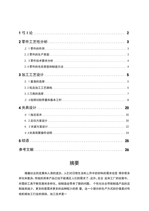
法兰盘零件加工工艺及夹具设计
加工路线方案的比较是保证加工表面的加I:精度和粗糙度的加工要求,根据 以上的加工路线原则等合理的设计两套方案,并进行合理的分析与选择,优胜劣 汰,淘汰掉加工过程中在生产成本、时间、生产效率等的基础上比不上另一套方 案的加工工艺方案。因此选择两个方案比较决定其中一个作为零件的加工工艺路 线:
农3.1加工工艺方案一
退刀槽
60
车
精车<1)100mm端而、外圆,精车B而,车过渡圆角R5
70
钻
钻4)18,扩4)19.8,较Q20mm孔成
80
铳
粗铳、精铳e90mm柱体的两侧面
90
钻
钻4X <l> 9mm透孔
100
钻
钻d)4mm通孔,扩G 6mm孔深7mm
110
磨
磨“45外圆靠"45左端而保证光洁度
120
抛光
B面抛光
续表3・3
70
钻
钻4)18,扩4)19.8,较©20mm孔成
80
铳
粗铳、精铳e90mm柱体的两侧面
90
钻
钻4X <l> 9mm透孔
100
钻
钻d)4mm通孔,扩(t> 6mm孔深7mm
110
磨
磨“45外圆靠"45左端而保证光洁度
120
抛光
B面抛光
130
镀箔
100m m外圆镀洛
140
检验
检验入库
经过表3.1和表3.2的加工方案的对比,发现方案一的钻扩较"20孔时车端 面后进行的。而方案二是加工完表面后钻孔,从加工顺序原则等的角度来看,先 主后次的原则,内孔"20并不是重要加工表面,在工步加工顺序中内孔"20定 位是在铳两端面的工序,因此选择为方案二作为法兰盘的加工工艺路线。
(完整版)毕业设计-法兰盘加工工艺及夹具设计(最新整理)
摘要工艺学是研究机械加工工艺技术和夹具设计为主的技术学科,具有很强的实践性,要求学习过程中应紧密联系生产实践,同时它又具有很强的综合性。
本次毕业设计研究的课题是法兰盘加工工艺及夹具的设计,主要内容如下:首先,对零件进行分析,主要是零件作用、结构和工艺的分析,通过零件分析可以了解零件的基本情况,而工艺分析可以知道零件的加工表面和加工要求。
根据零件图提出的具体加工要求,确定毛坯的制造形式和尺寸。
第二步,进行基面的选择,确定加工过程中的粗基准和精基准。
根据选好的基准,制定工艺路线方案,通常情况下制定两种以上的工艺路线方案,通过工艺方案的比较分析,再确定出可以使零件的几何形状、尺寸精度及位置精度等技术要求得到合理保证的工艺路线方案。
第三步,根据已经确定的工艺路线,选择加工设备及工艺装备,再确定每一工步的切削用量及时间定额。
第四步,设计工序Ⅶ—钻法兰盘4mm斜孔的夹具。
先提出夹具设计任务,选择定位基准,再确定夹具结构方案,然后开始切削力、夹紧力的计算和定位误差的分析。
最后,把整个设计过程整理为设计说明书和图纸,至此整个设计基本完成。
关键词:法兰盘;加工工艺;夹具设计。
AbstractTechnology is the study of machining fixture design technology and technology-based disciplines, with a very practical, requiring close contact with the learning process should be productive practice, but it also has a strong and comprehensive.The issue is the graduation of flange and fixture design process, the following key elements: First, the analysis of parts, mainly the role of parts, structural and process analysis, part by part analysis to understand the basic situation, The process analysis to know the machining surface and machining requirements. According to the specific part drawing processing requirements, to determine the manufacture of blank forms and dimensions.The second step, the choice of the base surface to determine the processing of coarse and fine reference base. According to the chosen benchmark, the development process route programs, usually two or more of the process line development program, through the process of comparative analysis of the program, and then determine the geometry can make the part shape, size and location accuracy of a reasonable accuracy and other technical requirements programs to ensure the process route.The third step, according to process routes have been identified, select the processing equipment and process equipment, and then determine the amount of each process step of cutting and time fixed for the rough.The fourth step, the design process Ⅶ - 4mm Flange drilling inclined holes of the fixture. To present the fixture design task, select locating datum, and then determine the fixture structure solution, and then began cutting force, clamping force calculation and analysis of positioning error.Finally, the process of finishing the entire design specifications and drawings for the design, bringing the whole design is basically completed.Keywords: Flange; Processing Technology; Fixture Design.第1章绪论1.1机械加工工艺的发展现状随着机械制造业的发展和科学技术的进步,机械制造工艺的内涵和面貌下不断发生变化,近一二十年的技术进展主要表现在以下几方面:(1)常规工艺的不断优化常规工艺的方向是实现高效化、精密化、强韧化、轻量化,以形成优质高效、低耗少污染的先进实用工艺为主要目标,同时实现工艺设备、辅助工艺、工艺材料、检测控制系统的成套工艺服务,使优化工艺易于为企业所采用。
机械工艺夹具毕业设计99法兰盘加工工艺及夹具设计
全日制普通本科生课程论文(设计)法兰盘加工工艺及夹具设计FLANGE AND THE FIXTURE DESIGN PROCESS学生姓名:学号:年级专业及班级:指导老师及职称:学院:目录摘要: (3)关键词: (3)1前言 (3)2零件的分析 (4)2.1零件的作用 (4)2.2零件的工艺分析 (4)2工艺规程设计 (5)2.1确定毛坯的制造形式 (5)2.2生产类型 (6)2.3工艺安排的基本倾向 (6)2.4设备选择 (6)2.5工艺手段 (6)2.6基面的选择 (6)2.7工件表面加工方法的选择 (7)2.8制订工艺路线 (8)2.9机械加工余量、工序尺寸及毛坯尺寸的确定 (9)2.10确定切削用量和基本工时 (9)3结论 (13)参考文献 (13)法兰盘加工工艺及夹具设计摘要:本课程设计主要内容是法兰盘(CA6140车床)的加工工艺过程设计,在课程设计过程中完成了零件图、毛坯图、的绘制。
机械制造工艺学课程设计是在我们完成了全部基础课、技术基础课、大部分专业课之后进行的。
这是我们对所学各课程的一次深入的综合性的复习,也是一次理论联系实际的训练。
能够顺利的完成这次课程设计,首先得助于董亮老师的悉心指导,同学们的耐心解答。
在设计过程中,缺乏实际的生产经验,导致在设计中碰到了许多的问题。
但在同学们的帮助下,通过请教老师,翻阅资料、查工具书,解决设计过程中的一个又一个的问题。
在此,十分感谢董亮老师的细心指导,感谢同学们的互相帮助。
关键词:法兰盘;工艺;设计;FLANGE AND THE FIXTURE DESIGN PROCESSStudent:WangMaqiangTutor:DongLiang(College o f Science and Technology, Hunan Agricultural University, Changsha 410128, China)Abstract:This course is primarily designed flange (CA6140 lathe) in the course of the design process, the process of curriculum design in completed parts map, blank map, the map. Machinery manufacturing technology in our curriculum design is based on the completion of all courses, technical basic course, after the majority of courses. This is what we have learned on the course of an in-depth comprehensive review, is also a theory with practice and training. The smooth completion of the course design, first of all have to help Dong Liang guidance teachers, the students answered the patient. During the design process, the lack of actual production experience.Resulted in the design of many of the problems encountered. However, the help of students, through to ask teachers, through information, search tool, the design process to solve the issues one after another. At this point, very grateful to the teacher's careful guidance Dong Liang, thanks to the students to help each other.Key words: Flange;Technology;design1前言机械制造工艺学课程设计使我们学完了大学的全部基础课、技术基础课以及大部分专业课之后进行的.这是我们在进行毕业设计之前对所学各课程的一次深入的综合性的总复习,也是一次理论联系实际的训练,因此,它在我们四年的大学生活中占有重要的地位。
ca6140车床法兰盘加工工艺规程及夹具设计毕业设计

ca6140车床法兰盘加⼯⼯艺规程及夹具设计毕业设计毕业设计CA6140车床法兰盘加⼯⼯艺规程及夹具设计⽬录1、⼯艺设计说明书. . . . . . . . . . . . . . . . . . . . . . . . . . . . . . . . . . .12、夹具设计说明书. . . . . . . . . . . . . . . . . . . . . . . . . . . . . . . . . . .203、课程设计体会. . . . . . . . . . . . . . . . . . . . . . . . . . . . . . . . . . . . .20第⼀部分⼯艺设计说明书1. 零件图⼯艺性分析1.1零件结构功⽤分析法兰盘是可⽤于连接其他零件或可⽤于增加其他零件强度的⼀种零件。
本法兰盘是回转⾯和平⾯的结合,内部由阶梯孔和螺纹孔组成,其要求有较⾼的耐磨性,较⾼的强度和回转稳定性。
1.2零件技术条件分析 1)法兰盘本⾝精度:外圆φ8019.00-+尺⼨公差等级IT11,表⾯粗糙度Ra 为1.6µm ,φ52029.001.0--尺⼨公差等级为IT6,表⾯粗糙度Ra 为1.6µm ,φ1201±尺⼨公差等级IT14,表⾯粗糙度Ra 为3.2µm ,内孔φ62015.0±公差等级为IT7,φ3602.0-+尺⼨公差等级IT6,φ65表⾯粗糙度Ra 为1.6µm ,距离φ36002.0-+为34.580.030.0--的平⾯公差等级IT13。
2)位置精度,内孔φ62015.0±相对于基准⾯A 、B 的跳动量要求为0.04。
3)加⼯此零件时,应尽量统⼀定位基准,减少装夹次数,这样有利于保证零件的加⼯精度。
1. 3零件结构⼯艺性分析此法兰盘是由回转⾯和平⾯组成,由零件图可知,该零件结构较为简单,但零件精度要求⾼,零件选⽤材料HT150,该材料⽤于强度要求不⾼的⼀般铸件,不⽤⼈⼯实效,有良好的减振性,铸造性能好。
法兰盘零件加工工艺及夹具设计【毕业作品】
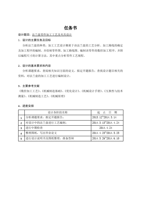
任务书设计题目1.设计的主要任务及目标分析法兰盘的种类,加工工艺设计侧重于该法兰盘的工艺分析、加工路线的确定及加工程序的编制。
并绘制零件图、加工路线图。
编制该零件的数控加工程序,并附以编程尺寸的计算方法,其中重点分析零件工艺规程。
2.设计的基本要求和内容分析课题要求,查阅相关知识方面的论文,拟定开题报告;查找设计题目相关的资料;对法兰盘的加工工艺进行编制设计;3.主要参考文献《数控加工工艺》、《机械制造基础》、《优化设计》、《机械设计手册》、《互换性与技术测量》、《机械制造工艺》、《机械原理》4.进度安排法兰盘零件加工工艺及夹具设计摘要:法兰盘是一种盘状零件,法兰盘也叫法兰,成对使用。
为了保证产品的质量,提高加工效率,需要对其加工工艺进行优化设计,并在关键工序使用专用机床进行加工。
本课题即以此为背景,要求学生根据企业生产需要和支座体零件的加工要求,首先完成零件的加工工艺规程设计,在此基础之上,选择其关键工序之一进行专用夹具设计,并完成必要的设计计算。
通过查阅相关资料,了解法兰盘用途,性能,特点,看懂零件图,确定毛坯,绘制毛坯图,拟定法兰盘工艺路线,制作工艺卡片等。
近几年来,我国在法兰的制造领域和研发领域取得了一定的突破。
机械制造工业是为社会提供各种机械设备的部门,在国家的发展中起到很重要的地位,其发展规模及水平反映了一个国家经济实力科技水平的标志。
此设计是在大学即将结束前学完了所有学校所安排的课程及实习后所面临的一次考察,是一次理论加实践的一次训练。
强化了我们对基础知识和技能的理解和应用程度,培养了我们一定的理论分析,设计运算能力,论证能力,搜集资料能力。
在我们四年的大学生活中占很重要作用。
关键词:法兰盘,工艺卡片,毛坯图,夹具设计The flange parts processing technology and fixture designAbstract:The flange disc is a disc like parts, also called flange flange, used in pairs. In order to ensure product quality, improve processing efficiency, need to optimize the design of the process, and use the special machine in key process of machining. This issue is based on the background, ask the students to processing enterprises production needs and support body parts requirements, complete the components processing technological process design first, on this basis, choose one of the key process of special fixture design, and completes the essential design calculation. Through access to relevant information, understand the flange uses, properties, characteristics, understand the part drawing, determine blank, drawing blank map, drawn up flange process route, process cards etc.. In recent years, our country have made a breakthrough in the field of manufacturing and R & D flange. Machinery manufacturing industry is to provide all kinds of machinery and equipment of the Department for the society, play a very important role in the development of the nation, the development scale and level reflects the symbol of the economic strength of a country's scientific and technological level. This design is in the University before the end learned all the school curriculum and an expedition faced after practice, is a theoretical and practical training session. Strengthening the basic knowledge and skills to understand and application level, trained to analyze our certain theory, design and operation ability, reasoning ability, ability to collect information. Plays an important role in our four years of University life.Keywords: flange, process card, blank map, fixture design目录1 绪论 (1)1.1本课题的意义和研究内容 (1)1.2 本课题应达到的要求 (1)2 法兰盘的工艺分析及生产类型的确定 (3)2.1 法兰盘零件的用途 (3)2.2 法兰盘零件的工艺分析 (3)2.3确定生产纲领和生产类型 (5)3 确定毛坯、绘制毛坯图 (7)3.1 选择毛坯 (7)3.2确定尺寸公差及加工余量 (7)4 拟定法兰盘工艺路线 (8)4.1 精基准的选择 (8)4.2 粗基准的选择 (8)4.3 加工阶段的划分 (8)4.4 工序集中与分散 (8)4.5 工艺路线的选择 (8)4.5.1 工艺路线方案一 (9)4.5.2 工艺路线方案二 (9)4.6 工艺方案的分析 (9)4.7 最终的加工工艺过程 (10)5 加工余量、工序尺寸和公差的确定 (11)5.1 加工余量的确定 (11)5.2 工序尺寸与公差的确定 (11)5.3 Φ320MM外圆加工余量、工序尺寸和公差的确定 (11)5.4 Φ248MM外圆加工余量、工序尺寸和公差的确定 (12)5.5 Φ320MM左端面加工余量、工序尺寸和公差的确定 (14)6 确定切削用量及基本工时 (18)6.1 合理选择切削用量 (18)6.1.1 背吃刀量 A P的选择 (18)6.1.2 进给量 F的选择 (18)6.1.3 切削速度VC的选择 (18)6.2 粗加工切削用量选择原则 (19)6.2.1 切削深度选择 (20)6.2.2 进给量选择 (21)6.2.3 切削速度选择 (21)6.3 精加工时切削用量选择原则 (21)6.3.1 切削深度选择 (21)6.3.2 进给量选择 (21)6.3.3 切削速度选择 (22)7 孔的夹具设计 (23)7.1 研究原始资料,确定夹具的设计方案 (23)7.1.1 分析工件并确定定位方案 (23)7.2 确定夹具总装配图的设计 (24)7.2.1 钻模的选择 (24)7.2.2 钻模板的选择 (24)7.2.3 钻套的选择与设计 (25)7.2.4夹具体定位元件的确定 (26)7.2.5工件定位元件的确定 (26)7.2.6回转分度装置 (28)7.2.7 对定分度装置机构 (29)7.2.8 定位器原理 (29)7.3 夹具的总装配与原理 (30)8 法兰盘夹具设计 (31)8.1 定位基准的选择 (31)8.1.1选择定位基准的基本方法 (31)8.1.2 粗基准的选择 (31)8.1.3 精基准的选择 (32)8.2 确定切削用量及基本工时 (32)8.2.1 车Φ320端面和外圆 (32)8.2.2 半精车Φ320端面和外圆 (33)8.2.3 钻Φ3-12MM孔 (33)8.3 定位误差分析 (34)8.4 夹具设计及操作的简要说明 (34)结论 (36)参考文献 (37)致谢 (37)附录 (38)1 绪论1.1 本课题的意义和研究内容法兰盘是工业中应用广泛的零件之一,生产量比较大。
毕业设计(论文)-法兰盘的专用夹具设计[管理资料]
![毕业设计(论文)-法兰盘的专用夹具设计[管理资料]](https://img.taocdn.com/s3/m/29ca9aa177232f60dccca196.png)
高等教育自学考试毕业论文学生姓名:考籍号:专业年级:模具制造与设计题目:法兰盘的专用夹具设计指导教师:评阅教师:年月目录●前言..................................................................................................................................... - 4 -●............................................................................................................................................. - 5 -●. (5)● (5)●、确定生产类型 (5)●............................................................................................................................................. - 5 -●. (6)● (6)⏹粗基准的选择............................................................................................................ - 6 -⏹...................................................................................................................................... - 6 -●. (6)● (7)⏹工艺路线方案一........................................................................................................ - 7 -⏹...................................................................................................................................... - 7 -●、工序尺寸及毛皮尺寸的确定 (8)● (9)●........................................................................................................................................... - 12 -●.. (12)●: (12)●: (13)●: (13)● (13)⏹底座.......................................................................................................................... - 13 -⏹固定导向件.............................................................................................................. - 14 -⏹钻套、衬套的选择.................................................................................................. - 14 -⏹.................................................................................................................................... - 15 -●结束语............................................................................................................................... - 15 -●致谢............................................................................................................................... - 16 -●参考文献........................................................................................................................... - 17 -摘要本次设计了一套法兰盘的专用夹具设计。
车床法兰盘机械加工工艺及夹具设计
车床法兰盘机械加工工艺及夹具设计«机械制造工艺学»是机械专业的一门要紧专业课,是以研究机械加工工艺技术和夹具设计为主技术学科,具有专门强的实践性,要求学习过程中应紧密联系生产实践,同时它又具有专门强的综合性。
本次毕业设计的课题是CA6140车床法兰盘加工工艺规程及某一工序专用夹具设计,要紧内容如下:第一,对零件进行分析,要紧是零件作用的分析和工艺分析,通过零件分析能够了解零件的差不多情形,而工艺分析能够明白零件的加工表面和加工要求。
依照零件图提出的加工要求,确定毛坯的制造形式和尺寸的确定。
第二步,进行基面的选择,确定加工过程中的粗基准和精基准。
依照选好的基准,制订工艺路线,通常制订两种以上的工艺路线,通过工艺方案的比较与分析,再选择能够使零件的几何形状、尺寸精度及位置精度等技术要求得到合理的保证的一种工序。
第三步,依照差不多选定的工序路线,确定每一步的切削用量及差不多工时,并选择合适的机床和刀具。
关于粗加工,还要校核机床功率。
最后,设计第三道工序—钻法兰盘孔的夹具。
先提出设计问题,再选择定位基准,然后开始切削力、夹紧力的运算和定位误差的分析。
然后把设计的过程整理为图纸。
通过以上的概述,整个设计差不多完成。
关键词:法兰盘;加工工艺;夹具设计Abstract"Mechanical manufacturing technology" is a major course of mechanical engineering, studying mechanical processing technology and fixture design is given priority to technology subject, has a strong practicality, requirements in the learning process should be closely contact with production practice, at the same time it has a strong comprehensive.The subject of this graduation project is that CA6140 lathe ring flange processing technology rules and special-purpose jig of a certain process are designed, the main content is as follows:First of all, analyzing this part , it is mainly analysis of the function of the part and craft analysis to the part , through part analyzed can find out about basic situation of part, and craft analyzed may know the processing surface of the part and is it require to process. The processing demand put forward according to the part picture, confirm the manufacture form of the blank and sureness of the size.The second step, carry on the choice the base , confirm thick datum and precise datum in the processing course. According to the datum chosen , make the craft route , usually make the craft route of more than two kinds, with analyzing through the comparison of the craft scheme, and then choosing be able to make such specification requirements as the precision of geometry form , size of the part and precision of position ,etc. get a kind of process of the rational assurance s.The third step, according to the already selected process route, confirm for every steps of cutting consumption and basic man-hour , choose suitable lathe and cutter. To rough machining , will check the power of the lathe .Finally , design the third process - the jig getting into the hole of the ring flange. Put forward the question of designing first , and then choose to orient the datum , then the calculation that begins to cut strength , clamp strength and analysis of the localization error. Then put the design course in order as the drawing.Through the summary of the above, design and finish basically entirely.Keywords: Flange; Process the craft; The tongs design目录摘要..................................................................................................... 错误!未定义书签。
法兰盘加工工艺及夹具课程设计毕业设计

目录摘要:............................................................................................. 错误!未定义书签。
关键词:............................................................................................. 错误!未定义书签。
1前言 (2)2零件的分析 (2)2.1零件的作用 (2)2.2零件的工艺分析 (2)2工艺规程设计 (3)2.1确定毛坯的制造形式 (3)2.2生产类型 (3)2.3工艺安排的基本倾向 (3)2.4设备选择 (3)2.5工艺手段 (4)2.6基面的选择 (4)2.7工件表面加工方法的选择 (4)2.8制订工艺路线 (5)2.9机械加工余量、工序尺寸及毛坯尺寸的确定 (6)2.10确定切削用量和基本工时 (7)3结论 (11)参考文献 (11)1前言机械制造工艺学课程设计使我们学完了大学的全部基础课、技术基础课以及大部分专业课之后进行的.这是我们在进行毕业设计之前对所学各课程的一次深入的综合性的总复习,也是一次理论联系实际的训练,因此,它在我们四年的大学生活中占有重要的地位。
通过本次课程设计,应该得到下述各方面的锻炼:1 能熟练运用机械制造工艺学课程中的基本理论以及在生产实习中学到的实践知识,正确地解决一个零件在加工中的定位、夹紧以及工艺路线安排、工艺尺寸确定等问题,保证零件的加工质量。
2 提高结构设计的能力。
通过设计夹具的训练,应当获得根据被加工零件的加工要求,设计出高效、省力、经济合理而且能保证加工质量的夹具的能力。
3 学会使用手册及图表资料。
掌握与本设计有关的各种资料的名称、出处、能够做到熟练运用。
就我个人而言,我通过这次课程设计,锻炼了自己分析问题、解决问题的能力,对零件的加工设计程序有了比较深的认识。
法兰盘夹具设计毕业设计
法兰盘夹具设计毕业设计法兰盘夹具设计毕业设计在工业生产中,夹具是一种重要的工具,用于固定工件以便进行加工和加工。
夹具的设计对于产品的质量和生产效率至关重要。
本文将探讨法兰盘夹具的设计,以及在毕业设计中如何应用这一技术。
一、法兰盘的概述法兰盘是一种连接管道和设备的重要部件。
它通常由两个法兰和一个密封垫片组成。
法兰盘的主要功能是连接和密封管道系统,以确保流体或气体的正常流动。
在工业生产中,法兰盘广泛应用于石油化工、船舶、电力、水处理等领域。
二、夹具的作用夹具是一种用于固定工件的工具。
它可以保持工件在加工过程中的稳定性,从而提高加工精度和效率。
夹具的设计需要考虑工件的形状、尺寸和材料等因素,以确保夹具能够牢固地固定工件。
三、法兰盘夹具的设计要求1. 稳定性:法兰盘夹具的设计需要确保工件能够稳定地固定在夹具上,以避免加工过程中的振动和位移。
2. 精度:夹具的设计需要考虑工件的加工精度要求,以确保夹具能够提供足够的固定力和刚度,以保持工件的准确位置。
3. 可调性:夹具的设计需要考虑工件的不同尺寸和形状,以便夹具能够适应不同的工件。
4. 安全性:夹具的设计需要考虑操作人员的安全,以避免夹具在使用过程中产生意外伤害。
四、法兰盘夹具设计的步骤1. 确定夹具类型:根据工件的形状和尺寸,选择合适的夹具类型。
常见的夹具类型包括平口夹具、U型夹具和V型夹具等。
2. 确定夹具结构:根据工件的特点和加工要求,确定夹具的结构。
夹具的结构应包括夹具底座、夹具夹持部件和夹具固定部件等。
3. 设计夹具夹持部件:根据工件的形状和尺寸,设计夹具夹持部件。
夹具夹持部件应具有足够的固定力和刚度,以确保工件在加工过程中的稳定性。
4. 设计夹具固定部件:根据夹具的结构和工件的特点,设计夹具固定部件。
夹具固定部件应能够牢固地固定夹具,以确保夹具在加工过程中的稳定性。
5. 进行夹具试验:设计完成后,进行夹具试验以验证夹具的性能。
夹具试验应包括夹持力、刚度和稳定性等指标的测试。
法兰盘零件加工工艺与夹具设计毕业设计说明书
③螺纹: M 64 1.5 mm,普通细牙螺纹,公差等级为 IT6,表面粗糙
度为 Ra3.2um。 ④切面:大圆切面与 120±1 的轴心线距离 34.500..2400 mm,公差等级
为 IT11,表面粗糙度为 Ra3.2。
(2)法兰盘的位置精度
第 4 页 共 34 页
毕业设计说明书
度、耐磨性、耐热性及减震性,适用于承受较大应力、要求耐磨的零
件。
(1)法兰盘的精度要求
①外圆:8000.19 尺寸公差等级 IT11,表面粗糙度 Ra 为 1.6μm。
52 0.01 0.029
尺寸公差等级为
IT6,表面粗糙度
Ra
为
1.6μm,120
1尺
寸公差等级 IT14,表面粗糙度 Ra 为 3.2μm。
的外圆和
120
1
的外圆、粗镗
金
半精
40 车
3600.02
的内孔、半精镗
36
0.02 0
的内孔
加 工
CA6140 车床
90°外圆车刀,镗刀
粗镗 62.4、62 0.015 、 65、及 4×0.5 的槽、
金
50 粗镗 58 的内孔、半精镗 65、62 0.015 及 4×0.5 加
工 的槽、车出 M64×1.5 的螺纹
第 4 章 夹具设计.........................................23
4.1 工序尺寸精度分析.....23 4.2 定位方案确定.....23 4.3 定位元件确定.....23 4.4 定位误差分析计算.....24 4.5 设计钻套,连接元件及夹具体,钻模板.....25 4.6 夹具总装草图.....26
CA6140车床法兰盘加工工艺及夹具毕业设计论文
目录1零件的分析 (2)1.1零件的作用 (2)1.2零件的工艺分析 (2)2工艺规程设计 (3)2.1确定毛配的制造形式 (3)2.2基面的选择 (3)2.3制定工艺路线 (4)2.4机械加工余量、工序尺寸及毛坯尺寸的确定 (5)2.5确定切削用量及基本工时 (11)总结 (53)参考文献 (54)1零件的分析1.1零件的作用CA6140卧式车床上的法兰盘,为盘类零件,用于卧式车床上。
车床的变速箱固定在主轴箱上,靠法兰盘定心。
法兰盘内孔与主轴的中间轴承外圆相配,外圆与变速箱体孔相配,以保证主轴三个轴承孔同心,使齿轮正确啮合。
主要作用是标明刻度,实现纵向进给。
1.2零件的工艺分析法兰盘是一回转体零件,有一组加工表面,这一组加工表面以Φ20045.00+mm 的孔为中心 ,包括:Φ12.034.0100--mm 的外圆柱面及左端面, 尺寸为Φ0017.045-mm的圆柱面,Φ90mm 的外圆柱面、右端面及上面的4个Φ9mm 的透孔, Φ06.045-mm 的外圆柱面及上面的Φ6mm ,Φ4mm 的孔, Φ90mm 端面上距离中心线分别为34mm 和24mm 的两个平面。
并且其余加工面都与它有位置关系,可以先加工它的一个端面,再借助专用夹具以这个端面为定位基准加工另一端面,然后再加工孔到尺寸要求,再以孔定位加工各个表面。
2工艺规程设计2.1确定毛配的制造形式零件材料为HT200,由于该零件是中批生产,而且零件轮廓尺寸不大,故采用金属模铸造,法兰盘因毛坯比较简单,采用铸造毛坯时一般是成队铸造,再进行机械加工。
这从提高生产率,保证加工精度上考虑也是应该的。
2.2基面的选择基面选择是工艺规程设计中的重要工作之一。
基面选择得正确与合理,可以使加工质量得到保证,生产率得以提高。
否则,加工工艺过程中会问题百出,更有甚着,还会造成零件大批报废,使生产无法正常进行。
1)粗基准的选择选择粗基准主要是选择第一道机械加工工序的定位基准,以便为后续的工序提供精基准。
法兰盘零件机械加工工艺及夹具设计
摘要法兰盘作为生活中一种常用的零件,它的外形是一个近似盘类的金属块,并在其周围均匀的开通孔用来连接另外的零件,与之匹配的还有垫圈螺栓之类的零件,起到密封以及防止变形的作用,用螺栓起到连接的作用,一般情况下法兰盘都是成对使用的。
本次我的毕业论文设计的题目是CK6140车床法兰盘零件的工艺规程和其专用夹具的设计,本文主要内容如下:首先,我们要对该法兰盘的零件进行分析,包括选用什么样的材质,以及选用该材质运用什么样的制造方法得出,根据法兰盘零件的材质考虑用锻造还是铸造。
主要是针对其零件的作用分析以及工艺性分析,通过对该零件认真透彻的分析,则可以了解该工件的基本构造情况,如果想要进一步了解该法兰盘零件的加工表面和加工工艺要求,则需要对其进行工艺分析,接下来就可以按照零件图提出的加工要求来确定毛坯图的尺寸以及要求。
其次,如果要确定该零件加工过程中的粗基准与精基准如何选择,就要对其进行基面的选择。
再按照选好的基准,用来确定该工件的加工工艺路线,一般情况下,当加工一个零件的时候,则要制定两种或两种以上的工艺路线,通过比对这两种工艺方案,再根据零件的尺寸精度、几何形状以及位置精度等级的技术分析选择出一条合理的工序路线。
然后,根据上面已经选定好的工序路线,选择合适的机床、量具以及刀具,并计算每一步的切削用量以及加工工时。
最后,设计专用夹具,在设计前先分析零件,之后参考相关的机床夹具手册设计构思出自己的原理来,紧接着设计出夹具方案,该方案既要满足零件的加工精度要求,还要能合理的对工件进行安装、定位以及夹紧;接下来参考零件的技术等级要求,选择出合理且相对应的材料。
在完成了所有的设计以及计算后,运用AutoCAD对其进行二维图形的绘制,并标注相关的尺寸以及技术要求,这样,就可以使读者清楚的了解所讲述的内容。
关键词:法兰盘,工艺卡片,零件图,夹具设计AbstractFlange as a common parts in life, its shape is a similar to the disk-like metal block, and around its open hole is used to connect other parts, matching with the washer bolts and other parts, plays the seal as well as prevents the distortion the function, uses the bolt to play the connection the function, under the general situation the Flange is used in pairs. The subject of my graduation thesis design is CK6140 lathe flange parts and the design of its special fixture, the main content of this paper is as follows: First, we want to analyze the flange parts, include what kind of material to choose, and what kind of manufacturing method to choose that material to use, according to the material of flange parts to consider forging or casting. It is mainly the function analysis and the craft analysis of the flange part. on the craft analysis to it, then may according to the part drawing the processing request to determine the blank drawing size as well as the request. Secondly, if we want to determine how to choose the coarse datum and the fine datum in the machining process of the part, we should choose the datum. Then, according to the selected datum, the processing route of the flange parts is determined. Usually, two or more processing routes need to be worked out After comparing the two schemes, the best process of the parts. Then, according to the above process has been selected, select the appropriate machine tools, measuring tools and tools, and calculate each step of the cutting amount and processing time. Finally, we design the special fixture for the Flange. When designing the special fixture, we first carefully analyze the machining technical requirements of the part, and then refer to the fixture manual for the machine tool to design the basic principles and methods The Design Scheme of the special fixture is drawn up, and the fitting, positioning and clamping are carried out reasonably under the requirement of the machining precision of the part. After the completion of all the design and calculation, the use of AUTOCAD for its two-dimensional graphics drawing, and mark the relevant size and technical requirements, so that the reader can clearly understand the content.Key words: Flange, process card, part drawing, fixture design目录摘要 (1)Abstract (2)第一章前言 (4)1.1法兰盘国内外的发展现状 (4)1.2本论文的意义和研究内容 (4)1.3该论文要达到的要求 (5)第二章工件的分析 (6)2.1法兰盘零件图的工艺性分析 (6)2.2工件的结构作用及功能分析 (6)2.3零件技术条件分析 (7)2.4零件结构工艺性分析 (8)第三章法兰盘加工工艺规程设计 (8)3.1毛坯的类型 (8)3.2毛坯余量的确定 (8)3.4工件表面加工方法的分析与确定 (9)3.5工艺路线的制定 (10)3.5.1方案一: (10)3.5.2工艺路线方案二: (11)3.6定位基准的选择 (11)3.6.1粗基准的选择 (12)3.6.2精基准的选择 (12)3.7零件加工阶段的划分说明 (13)3.8工序尺寸及其公差的确定 (13)3.8.1基准重合时工序尺寸的确定 (13)3.8.2基准不重合时工序尺寸确定 (15)3.9零件的加工设备及其工艺装备的确定 (16)3.10切削用量及基本工时的确定 (16)第四章夹具设计 (26)4.1提出问题 (26)4.2设计专用的钻床夹具 (27)4.2.1 选择夹具的定位元件 (27)4.2.2分析定位误差 (27)4.2.3钻削力的计算 (28)4.2.4夹紧装置的设计与夹紧力的计算 (29)4.3夹具结构设计及操作简要说明 (31)4.3.1底座 (31)4.3.2钻套及衬套的选择 (31)4.3.3夹紧机构 (32)结论 (32)参考文献 (33)第一章前言1.1法兰盘国内外的发展现状机械制造业是一个国家工业发展的支柱,它为新技术的研发和产品的更新迭代起着重要的作用,是非常重要的战略性产业。
法兰盘加工工艺及铣夹具设计

6.3mm
IT13
钻
φ45 mm外圆面
0.8mm
IT6~IT7
粗车→精车→粗磨→精磨
距离24mm的平面
0.4mm
粗铣→精铣→磨削.
距离轴线34mm被铣平面
3.2mm
粗车→半精车→精车。
2.3工艺路线的拟定及工艺方案个分析
1)工艺路线的拟定
根据法兰盘零件在批量生产,所以使用常用工具,并配合专用夹具,刀具,考虑集中式流程,以提高生产率,减少使用,降低生产成本。经过对法兰盘的工艺分析,零件的毛坯为金属模、机械造型精度为2级,并经人工时效处理,消除铸件的内应力,改善了工件的可切削性。
关键词法兰盘加工工艺切削用量夹具
This isreferred to as the flange parts of a disc type parts, its function is also used to connect metal parts, usually at the beginning of a similar dish shaped around the through-hole for fixing the set. Inthe application field of machinery flange is wide, so it's all sorts of strange things in different shapes.
第一个工序粗车Φ100A面、及其Φ100外圆面,粗车B面以及粗车Φ90的外圆面
1.加工条件
毛坯材料:Ⅱ级精度,金属模铸造,HT200
机床选择:C365L转塔式车床
刀具选择:选用93偏头端面车刀,刀杆尺寸16x25mm ,主偏角 =90 ,副偏角 =15 ,
- 1、下载文档前请自行甄别文档内容的完整性,平台不提供额外的编辑、内容补充、找答案等附加服务。
- 2、"仅部分预览"的文档,不可在线预览部分如存在完整性等问题,可反馈申请退款(可完整预览的文档不适用该条件!)。
- 3、如文档侵犯您的权益,请联系客服反馈,我们会尽快为您处理(人工客服工作时间:9:00-18:30)。
摘要工艺学是研究机械加工工艺技术和夹具设计为主的技术学科,具有很强的实践性,要求学习过程中应紧密联系生产实践,同时它又具有很强的综合性。
本次毕业设计研究的课题是法兰盘加工工艺及夹具的设计,主要内容如下:首先,对零件进行分析,主要是零件作用、结构和工艺的分析,通过零件分析可以了解零件的基本情况,而工艺分析可以知道零件的加工表面和加工要求。
根据零件图提出的具体加工要求,确定毛坯的制造形式和尺寸。
第二步,进行基面的选择,确定加工过程中的粗基准和精基准。
根据选好的基准,制定工艺路线方案,通常情况下制定两种以上的工艺路线方案,通过工艺方案的比较分析,再确定出可以使零件的几何形状、尺寸精度及位置精度等技术要求得到合理保证的工艺路线方案。
第三步,根据已经确定的工艺路线,选择加工设备及工艺装备,再确定每一工步的切削用量及时间定额。
第四步,设计工序Ⅶ—钻法兰盘 4mm斜孔的夹具。
先提出夹具设计任务,选择定位基准,再确定夹具结构方案,然后开始切削力、夹紧力的计算和定位误差的分析。
最后,把整个设计过程整理为设计说明书和图纸,至此整个设计基本完成。
关键词:法兰盘;加工工艺;夹具设计。
AbstractTechnology is the study of machining fixture design technology and technology-based disciplines, with a very practical, requiring close contact with the learning process should be productive practice, but it also has a strong and comprehensive.The issue is the graduation of flange and fixture design process, the following key elements: First, the analysis of parts, mainly the role of parts, structural and process analysis, part by part analysis to understand the basic situation, The process analysis to know the machining surface and machining requirements. According to the specific part drawing processing requirements, to determine the manufacture of blank forms and dimensions.The second step, the choice of the base surface to determine the processing of coarse and fine reference base. According to the chosen benchmark, the development process route programs, usually two or more of the process line development program, through the process of comparative analysis of the program, and then determine the geometry can make the part shape, size and location accuracy of a reasonable accuracy and other technical requirements programs to ensure the process route.The third step, according to process routes have been identified, select the processing equipment and process equipment, and then determine the amount of each process step of cutting and time fixed for the rough.The fourth step, the design process Ⅶ - 4mm Flange drilling inclined holes of the fixture. To present the fixture design task, select locating datum, and then determine the fixture structure solution, and then began cutting force, clamping force calculation and analysis of positioning error.Finally, the process of finishing the entire design specifications and drawings for the design, bringing the whole design is basically completed.Keywords: Flange; Processing Technology; Fixture Design.第1章绪论1.1机械加工工艺的发展现状随着机械制造业的发展和科学技术的进步,机械制造工艺的内涵和面貌下不断发生变化,近一二十年的技术进展主要表现在以下几方面:(1)常规工艺的不断优化常规工艺的方向是实现高效化、精密化、强韧化、轻量化,以形成优质高效、低耗少污染的先进实用工艺为主要目标,同时实现工艺设备、辅助工艺、工艺材料、检测控制系统的成套工艺服务,使优化工艺易于为企业所采用。
(2)新兴加工方法的不断出现和发展新兴加工方法包括精密加工、细微加工、特种加工及高密度能加工、新硬材料加工技术、表面功能性覆盖技术和复合加工,以适应机械产品更新换代对制造工艺提出的更高、更新的制造模式。
(3)自动化等高新技术与工艺的紧密结合微电子、计算机和自动化技术与工艺及设备相结合,使传统工艺面貌产生显著、本质的变化,如生产线自动控制、在线检测自适应控制、计算机辅助工艺过程设计、计算机辅助家具设计、计算机辅助装配工艺设计和智能制造系统等。
1.2现代机械加工工艺的发展现状机械制造是国民经济发展和各部门科技进步的基础。
在现代化条件下机械制造的发展方向是:开发工艺可行性广、能保证各种原料消耗最少、可靠性和自动化精度高的新一代技术。
机械制造工艺及其实现组织形成的发展趋势,在很大程度上取决于机器结构的发展方向和它的技术使用特征。
机器制造中的科技进步将促进以计算机和生产全盘自动化为基础的工序少和能源节约的工艺的建立推广。
机器制造工艺组织的远景发展的概念是考虑在集管理、信息和技术为一体的基础上建立全盘自动化工厂,将最终产品的各个加工阶段连接起来。
这时,在科技发展现阶段的自动化工厂将不是无人企业。
由人服务和管理的体系和机器会发挥作用。
新的智能型和集成型的生产手段与高度熟练的工作人员相结合,将在市场需求变化的条件下假造出满足技术和社会经济需求的先决条件。
在现今的发达国家中,毛坯生产的发展趋势表明,今后毛坯生产发展方向是力图在经济合理的范围内,使毛坯接近成品零件的尺寸形状。
这可降低金属消耗量,减少加工余量和毛坯及铁屑的运输费用,这样就可提高生产率,降低零件的加工成本。
对于毛坯生产,其特点主要是扩大新的先进的节约资源的工艺过程运用领域。
采用电子技术管理切削加工过程,提高了对毛坯质量精度的要求。
这将使其加工工艺得到必要的完善。
在不久的将来,精密金属摸铸造和压力铸造将取代砂型铸造。
有前途的制取毛坯的方法将会得到发展,其中包括等静压法、金属的压力喷射成型挤压、精密冲压、预热推挤方法等。
金属切削加工将被比较经济的制取零件的方法所取代(如冷推挤法)。
但由于所使用的设备昂贵,以及工件必须经过再次退火,使得这种方法只能在零件生产规模不少于100万件时,经济上才是合算的。
在金属切削机床上加工工艺的发展趋势,是扩大采用先进的工艺过程和提高加工自动化的程度。
提高生产率,降低切削加工成本,在很大程度上取决于刀具和刀具材料的技术可行性。
高速钢和烧结合钨硬质合金,由于价格相对较低,工具制造简单,耐磨性好,强度高,所以促使其得到了广泛的使用。
新型切削材料的使用有助于增大切削用量,提高生产率,扩大经济效益。
使粉末冶金高速钢工具,并且用物理沉积法涂上耐磨涂层,是很有发展前途的。
对于钢件的半精加工和精加工,采用以碳化钛、碳氮化钛为基的无钨硬质合金。
用细颗粒硬质合金代替高速钢,可提高加工生产指标率。
在加工韧性材料时,涂层硬质合金获得了越来越广泛的应用。
用化学气相沉积方法得到的陶瓷涂层的应用,可使切削速度大大提高,而这种切削速度在以前只有用矿物陶瓷切削刀具或金属陶瓷才能达到。
在加工淬火钢,尤其是铣齿和拉削方面,以及有色金属和合金的加工,非金属材料的加工,使用硬质合金也是有发展前途的。
在硬质合金刀片上镶上人造材料—多晶立方氮化硼,可用于加工硬度达HRC68的镍铬钢或铬镍钼钢,其切削速度可达130m/min。
在加工研磨性强的轻金属和非金属材料时,则采用多晶金刚石。
用碳化硅纤维增强的氧化物陶瓷,用于加工镍合金、渗碳和热处理后的钢以及灰铸铁。
氮化硅陶瓷在广泛的切削速度范围下使用(达1000m/min)。
氮化硅陶瓷现在用于灰铸铁、高温合金的加工,因为它有较高的抗扩散磨损的能力。
陶瓷结合剂的立方氮化硼砂轮、多孔砂轮和数控机床用的砂轮,具有寿命长、磨削性能稳定的特点。
今后在磨削中将使用优质的加入合金成分的刚玉砂轮、用球形刚玉制造的砂轮、高纯度单晶刚砂轮、高强度耐热人造单晶刚石的复合材料砂轮。
磨料的新型结合剂的开发将扩大高磨削的可能性。
除了上述传统切削加工方法之外,还有范围更广泛的非金属加工方法:电物理和电化学加工方法;微塑性变形尺寸加工法以及将两种以上物理本质各不相同的加工方法合在一起的复合加工方法(化学反应,电腐蚀和磨粒加工等)。
这些非传统方法的合理应用领域,是在那些采用传统切削方法不经济或在技术上不可能实现的那些工序。
这样,切削加工由于具有广泛的工艺可行性,所以它在使用机床的加工方法中仍会占有优先地位。
