CC3200模块资料
CC3200和CC3100 电路板设计重点 V1.0
SimpleLink TM Wi-Fi 芯片CC3200和CC3100 的电路板设计重点贺鹏,张信伟(Albin)目录1.产品综述2.电源部分的设计2.1芯片内部DC-DC2.2VbatDC-DC输入电容2.3电源部分地的处理2.4对Wi-Fi 性能的影响3.射频链路3.1带通滤波器(BPF)3.2射频走线的阻抗控制3.32.4GHz 天线3.4天线阻抗匹配3.5射频测试接口4.晶振电路设计4.1晶体选型4.2晶体的布板设计5.总结概要德州仪器(TI)产品线的SimpleLinkWi-Fi CC3200 和 CC3100是一颗针对广大物联网 (IoT) 市场的嵌入式 Wi-Fi 芯片。
TI SimpleLink Wi-Fi 拥有简单易用的软件构架和实例程序,芯片采用0.5mm 间距的64管脚QFN 封装,支持单端射频链路,大大降低了射频电路板设计的门槛。
对终端用户来说,既可以选择采用射频模块方案,也可以选择投入更多的研发资源,开发BOM成本更低的芯片贴板(COB, Chip on Board)的方案。
即使没有Wi-Fi或射频经验的硬件工程师来说,只要严格遵循TI开放的参考设计和设计规则,也可以开发出性能合格的嵌入式WiFi电路板。
本应用文档针对CC3200和CC3100自2014年7月投放市场以来,广大用户在电路板设计开发中遇到的常见问题,重点讲解电路板的设计重点,以及这些设计细节对最终产品Wi-Fi 性能的影响。
1.产品综述CC3200 和 CC3100都是TI SimpleLink TM系列的嵌入式Wi-Fi芯片。
CC3200 是一个支持Wi-Fi的片上系统 (SoC, System on Chip),包含一个Wi-Fi 网络处理器 (NWP, Network Processor),电源管理子系统外,和一颗ARM Cortex M4核的应用处理器。
CC3200 的应用处理器最高可达 80 MHz 主频,内置 256KB内存,为应用开发提供了丰富的接口和内部资源。
Uniflash使用手册 For CC3200.
Uniflash 使用手冊 For CC3200 Version v0.1
广州蜂汇科技有限公司
2014-12-01
广州蜂汇电子科技有限公司版权保留
1. 第一章模块接线说
明 (1)
2. 第二章固件烧写说
明 (1)
广州蜂汇电子科技有限公司版权保留
文档标题 1. 第一章模块接线说明
烧写 Flash 之前,需要接的引脚如下:
说明:
烧写固件时,必须将 SOP2引脚接 VCC ,烧写完成后,断开 SOP2 与 VCC 的连接,复位模块即可运行。
2. 第二章固件烧写说明
Uniflash 启动界面如下:
点击“ New Target Configuration”,如下:
直接点击“ OK ”,然后在 COM Port选择框中填入串口号,如下:
文档标题点击上图的/sys/mcuimg.bin,选择要烧写的 bin 文件,将 Erase,Update 和 Verify 选项框勾选上,如下:上述操作完成后,就可进行固件的烧写了,点击菜单栏的 Operation->Program 就可以了,如下: 3
文档标题 4。
wifi模块开发 芯片选型对比

Wifi模块开发调研本文对几款主流的wifi芯片进行对比,包括TI公司的cc3200,乐鑫的esp8266,联发科的mt7681。
通过了解它们的特点和开发环境等方面的需求,选取适用于自己使用的芯片来进行物联网wifi模块的开发。
1CC32001.1芯片简介CC3200是TI无线连接SimpleLink Wi-Fi和物联网(IoT)解决方案最新推出的一款Wi-Fi MCU,是业界第一个具有内置Wi-Fi的MCU,是针对物联网应用、集成高性能ARM Cortex-M4的无线MCU。
客户能够使用单个集成电路开发整个应用,借助片上Wi-Fi、互联网和强大的安全协议,无需Wi-Fi经验即可实现快速的开发。
CC3200是一个完整平台解决方案,其中包括软件、示例应用、工具、用户和编程指南、参考设计以及TI E2E支持社区。
CC3200采用易于布局的四方扁平无引线(QFN)封装。
有人科技的USR-C322模块采用的是TI的CC3200方案,基于ARM Cortex-M4内核,运行频率高达80MHz;超低功耗:低功耗,在网待机低至3.5mA,深度休眠最低25uA;Simplelink 功能:实现一键联入Wi-Fi网络;另外支持自定义网页、websocket、httpd client等功能。
1.2特点Wi-Fi网络处理器(CC3200)包含一个Wi-Fi片上互联网和一个可完全免除应用MCU处理负担的专用ARM MCU。
Wi-Fi片上互联网包含802.11b/g/n射频、基带和具有强大加密引擎的MAC,可以实现支持256位加密的快速安全的互联网连接。
Wi-Fi片上互联网还包括嵌入式TCP/IP和TLS/SSL协议栈、HTTP服务器和多种互联网协议。
CC3200支持站点、接入点和Wi-Fi直连3种模式,支持WPA2个人和企业安全性以及WPS2。
1.3开发支持官方提供的SDK包含用于CC3200可编程MCU的驱动程序、40个以上的示例应用以及使用该解决方案所需的文档。
一步一步学习WIFICC3200音频对讲
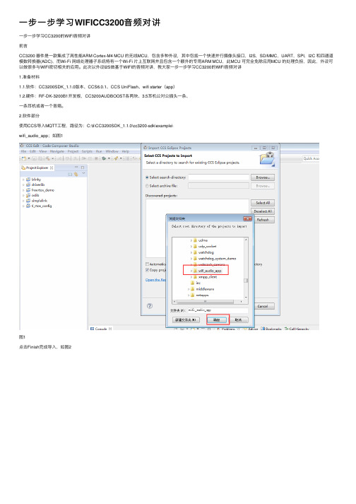
⼀步⼀步学习WIFICC3200⾳频对讲⼀步⼀步学习CC3200的WIFI⾳频对讲前⾔CC3200 器件是⼀款集成了⾼性能ARM Cortex-M4 MCU 的⽆线MCU,包含多种外设,其中包括⼀个快速并⾏摄像头接⼝,I2S,SD/MMC,UART,SPI,I2C 和四通道模数转换器(ADC),⽽Wi-Fi ⽹络处理器⼦系统特有⼀个Wi-Fi ⽚上互联⽹并且包含⼀个额外的专⽤ARM MCU,此MCU 可完全免除应⽤MCU 的处理负担,因此,外设可以做很多与WIFI密切相关的应⽤。
此次以外设I2S做基于WIFI的⾳频对讲,教⼤家⼀步⼀步学习CC3200的WIFI⾳频对讲1.准备材料1.1.软件:CC3200SDK_1.1.0版本、CCS6.0.1、CCS UniFlash、wifi starter(app)1.2.硬件:RF-DK-3200B1开发板,CC3200AUDBOOST各两块、3.5⽿机公对公插头⼀条、⼀条⽿机或者⼀个⾳箱。
2.软件部分使⽤CCS导⼊MQTT⼯程,路径为:C:\ti\CC3200SDK_1.1.0\cc3200-sdk\example\wifi_audio_app;如图1图1点击Finish完成导⼊,如图2导⼊后如图,如图3图3由于此程序有bug,需要我们根据TI CC3200 Issues来修改在wifi_audio_app⼯程的main.c⽂件中,修改位置为278⾏和289⾏;如图4中箭头所⽰,注释“if(RecordPlay & I2S_MODE_TX)”,加上“if(RecordPlay == I2S_MODE_RX_TX)”注释“if(RecordPlay == I2S_MODE_RX_TX)”,加上“if(RecordPlay & I2S_MODE_TX)”修改后效果如图5图5在main⽂件中,修改位置为322⾏和328⾏,如图6中箭头所⽰,取消注释“MAP_PinTypeGPIO(PIN_01, PIN_MODE_0, false);”取消注释“MAP_GPIODirModeSet(GPIOA1_BASE, 0x4, GPIO_DIR_MODE_OUT);”取消注释“MAP_PinTypeGPIO(PIN_02, PIN_MODE_0, false);”取消注释“MAP_GPIODirModeSet(GPIOA1_BASE, 0x8, GPIO_DIR_MODE_OUT);”修改后效果如图7图7在main⽂件中,修改位置为346⾏和351⾏,如图8中箭头所⽰,注释“if (RecordPlay == I2S_MODE_RX_TX)”,加上“if(RecordPlay & I2S_MODE_TX)”注释“if(RecordPlay & I2S_MODE_TX)”,加上“if(RecordPlay == I2S_MODE_RX_TX)”图8修改后效果如图9图9在wifi_audio_app⼯程的microphone.c⽂件中,修改位置为66⾏;如图10中箭头所⽰,注释“extern int g_loopback”,加上“extern char g_loopback”修改后效果如图11图11在wifi_audio_app⼯程的control.c⽂件中,修改位置为93⾏;如图12中箭头所⽰,加上“extern unsigned char g_loopback;”图12修改后效果如图13图13在wifi_audio_app⼯程的control.c⽂件中,修改位置为131,如图14中箭头所⽰,加上“#ifdef MULTICAST g_loopback = 0;#endif”修改后效果如图15图15在wifi_audio_app⼯程的control.c⽂件中,修改位置为216⾏;如图16中箭头所⽰,加上“ g_loopback = 0;”修改后效果如图17图17把程序保存,编译,并使⽤CCS UniFlash下载到CC3200的开发板上。
CC3200例程使用说明
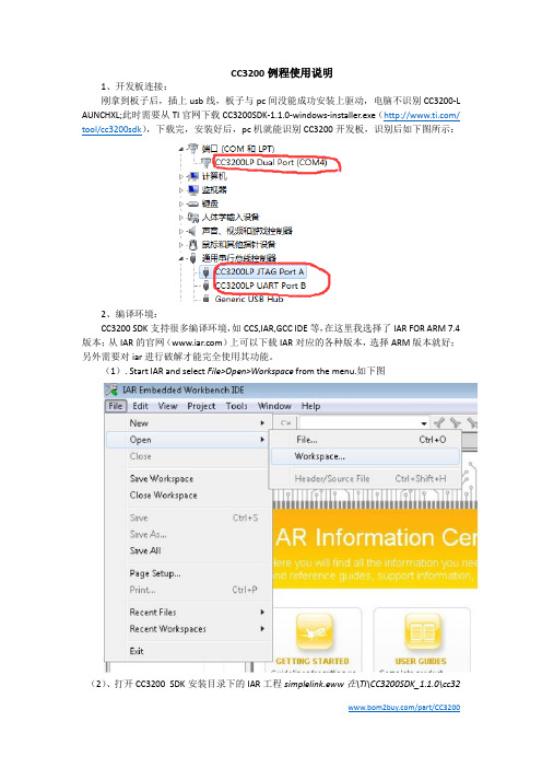
CC3200例程使用说明1、开发板连接:刚拿到板子后,插上usb线,板子与pc间没能成功安装上驱动,电脑不识别CC3200-L AUNCHXL;此时需要从TI官网下载CC3200SDK-1.1.0-windows-installer.exe(/ tool/cc3200sdk),下载完,安装好后,pc机就能识别CC3200开发板,识别后如下图所示:2、编译环境:CC3200 SDK支持很多编译环境,如CCS,IAR,GCC IDE等,在这里我选择了IAR FOR ARM 7.4版本;从IAR的官网()上可以下载IAR对应的各种版本,选择ARM版本就好;另外需要对iar进行破解才能完全使用其功能。
(1). Start IAR and select File>Open>Workspace from the menu.如下图(2)、打开CC3200 SDK安装目录下的IAR工程simplelink.eww在\TI\CC3200SDK_1.1.0\cc3200-sdk\simplelink\ewarm。
如下图所示:(3)、重新编译工程,用Project>Rebuild All或者如下图快捷键:3、例程运行:(1)、打开CC3200 SDK安装目录下的wlan_station的工程,在:\TI\CC3200SDK_1.1.0\cc320 0-sdk\example\ getting_started_with_wlan_station\ewarm;(2)、打开位于TI\CC3200SDK_1.1.0\cc3200-sdk\example\common\的common.h;(3)、通过编辑common.h里的宏:SSID_NAME, SECURITY_TYPE, and SECURITY_KEY来使用SSID名称,安全类型,AP的安全密码,如下图:(4)、保存commom.h;(5)、重新编译工程wlan_station;(6)、选项设置如下:(7)、我选择用SecureCRT作为串口工具,如下图:(8)、点击IAR工程上的下载按钮,并运行;(9)、在SecureCRT上会出现如下图字符,并且要求输入SSID名字,输入后等待客户端进行连接,如下图;在电脑端无线网络也出现了我设置的HSD_xuhy名称;当我PC端连接名称为HSD_xuhy的wifi后,SecureCRT提示如下,显示成功。
基于CC3200的智能家居监控系统设计
基于CC3200的智能家居监控系统设计作者:郭书军范玉强来源:《物联网技术》2016年第10期摘要:本系统的设计主要包括硬件采集及控制电路,Linux下的Apache网页服务器的搭建和Android手机客户端的设计,可以实现数据的存储和查询以及便携式移动控制。
主要采用CC3200作为数据采集及控制端的微控制器,通过其芯片内置WiFi模块把数据上传至服务器,并从服务器返回控制信息,通过手机客户端访问服务器,服务器把数据返回手机客户端以实现远程数据传输和控制。
关键词:CC3200;WiFi模块;服务器;远程控制中图分类号:TP277 文献标识码:A 文章编号:2095-1302(2016)10-00-030 引言随着社会的发展及人们生活条件的改善,人们对安全问题越来越关注,尤其是家居安全方面。
入室盗窃、煤气泄漏、火灾等情况时有发生,在家里安装安全报警装置是家庭安全保障发展的趋势。
因此,我们设计了一种无线家居监控系统,充分利用互联网高速发展的优势,将互联网与家居、智能手机有机结合,实现了盗贼入侵报警、火灾报警、CO报警及远程检测室内环境变化并控制家用电器的开关等功能。
1 系统总体构成本系统主要由采集端、服务器和手机客户端组成。
系统总体结构如图1所示。
采集端负责CO、CO2、温湿度等传感器的数据采集并执行接收到的控制信息。
硬件平台由各种传感器和CC3200微控制器组成,软件采用CC3200编程以控制传感器的数据采集、上传数据以及执行控制命令。
服务器用于数据的中转,以便于数据远程传输与存储。
服务器端使用PHP语言编写与采集端、手机客户端及后台数据库的接口程序。
手机客户端用于实现实时监测及控制。
使用Android平台进行手机客户端软件开发。
2 硬件模块设计与实现本系统的硬件设计主要集中在采集端的硬件设计上。
2.1 硬件框图及各子模块功能2.1.1 采集模块采集模块包含CO传感器、CO2传感器、温湿度传感器、烟雾传感器等子模块。
CC3200LaunchPad使用入门SDK例程

CC3200 SDK实验操作指南Wlan StationV1.0目录1 简介 (2)1.1 实验描述 (2)1.2 准备工作 (3)1.2.1 软件准备 (3)1.2.2 跳线帽设置 (3)2 操作步骤 (4)2.1 板卡驱动测试 (4)2.2 编译库文件 (4)2.2.1 导入工程 (4)2.2.2 配置ti_rtos_config (5)2.2.3 库工程simplelink (6)2.2.4 库工程driverlib (6)2.2.5 库工程oslib (6)2.3 编译例程wlan_station (6)2.3.1 导入工程 (6)2.3.2 修改AP配置信息 (8)2.3.3 目标配置文件 (10)2.3.4 开启调试串口 (11)2.3.5 下载及运行结果分析 (12)3 附录 (14)3.1 常见问题 (14)3.1.1 不能识别串口设备 (14)3.1.2 复位后代码不见了 (14)3.1.3 编译提示错误未找到target (15)3.1.4 CC3200固件升级 (15)3.1.5 编译wlan_station时关闭工程ti_rtos_config (15)3.2 参考资料 (16)3.3 后记 (16)1简介CC3200是带Wi-Fi功能、集成Cortex-M4内核的处理器,提供单芯片的Wi-Fi解决方案。
CC3200 LaunchPad是基于该芯片的一款评估板,CC3200 SDK软件开发包是CC3200的软件开发包,支持CCS 6.0.1, IAR 7.20和GCC IDE等编译器。
SDK开发包中带有很多的例程,本文档将选取一个典型的例程——WLAN设备的应用,帮助用户了解基于CCS集成开发环境的全过程,如编译、下载和调试等操作。
1.1实验描述在实验中,我们使用的开发环境是CCS6.0集成开发环境,在CCS中导入工程、编译、下载例程WLAN Station到CC3200 LaunchPad评估板上,运行代码,并观察实验结果。
USR-C322-v2.3

电话:4000 255 652
USR-C322
3 -低功耗小尺寸 WiFi 模块用户手册 V2. V2.3
� � � � � � � � � � � � � � � � � � � � � �
支持 Wi-Fi@2.4 GHz 802.11b/g/n 无线标准 基于 ARM Cortex-M4 内核 运行频率 80MHz 支持 WEP、WPA/WPA2 安全模式 支持 AP/STA 工作模式 支持 Simplelink/usrlink 快速联网配置 支持网页自定义功能 完全集成的串口转无线 TCP/UDP 传输功能,串口速率高达 3M bit/s 支持 485 收发控制 可以实现双串口三 Socket 通信 支持 PC1 16 字节密钥透传加密 支持 HTTPD Client 功能 支持网页转串口功能 支持 SSL Client 通信 局域网搜索和无线参数设置功能 支持 TCP/UDP Client 注册包机制,支持用户自定义注册包 支持类 RFC2217 自动波特率适配功能 支持简单 AT+指令集配置 3.3V 单电源供电 超低功耗模式,支持深度休眠 可选择内置天线,外置天线(IPEX 连接器) 超小尺寸:18.22mm*26.65mm*2.8mm SMT 封装 CE/FCC 认证,符合 RoHS 标准源自济南有人物联网技术有限公司
第 1 页 共 57 页
USR-C322 低功耗小尺寸 WiFi 模块用户手册
电话:4000 255 652
目录
1、 产品介绍.................................................................................................
CC3200 LaunchPad物理网应用举例

CC3200 LaunchPad物联网应用Exosite Could例程V1.0目录1 基于IoT应用的演示例程 (2)1.1 Exosite Cloud演示程序 (2)1.2 准备工作 (3)1.2.1 硬件准备 (3)1.2.2 PC端的软件准备 (4)1.2.3 网络账号申请 (5)1.3 CC3200 LaunchPad程序下载 (5)1.3.1 打开配置文件 (5)1.3.2 输入COM端口 (6)1.3.3 擦除Flash操作 (7)1.3.4 Flash代码下载 (8)1.4 CC3200 LaunchPad网络配置 (8)1.5 将硬件添加到云账号下 (10)1.5.1 网站登录账号 (10)1.5.2 在网页中添加设备 (10)1.5.3 云端查看运行结果 (12)1.6 常见问题 (13)1.6.1 不能识别串口设备 (13)1.6.2 COM端口被占用 (13)1.6.3 CC3200 LaunchPad版本号查看 (14)1.6.4 出现Flash烧写错误的解决方法 (14)1.6.5 Exosite cloud demo源码下载 (15)1.7 COM调试接口的使用 (15)2 参考资料 (16)3 后记 (16)1基于IoT应用的演示例程1.1Exosite Cloud演示程序本文档的初衷在于帮助初次接触CC3200 LaunchPad的用户在最短的时间内完成一个IoT 程序。
该例程基于Exosite网站,暂且称之为Exosite Cloud演示程序。
这个程序有什么用呢?在这里先对运行结果简单说明下:程序正常运行时,CC3200 LaunchPad作为一个设备,通过一个无线网络接入互联网。
用户可以在任何一个有网络的地方,登录云服务器,远程查看CC3200 LaunchPad的温度测量值和加速度测量值;同时还可以对用户的按键操作进行计数显示;最后,可以通过网页上的按键,远程控制CC3200LaunchPad上的LED灯。
低功耗wifi CC3200模块介绍

ADC I2S
GPIO
6
STR-WF3200特点
低成本
提供多种天线接口
高度集成TCP / IP协议栈和服务应用 软件自带数据透传和AT命令操作模式
支持WPA2个人/企业级 加密 硬件加密引擎支持 TLS/SSL连接和 DES/AES256/MD5/SH A2加密
特点
安全 低功耗
低功耗射频: 37mA监听电流 54mA接收电流 低功耗模式:
最佳安全云链接
互联网连接加密 SSL 3.0 Wi-Fi连接加密 WPA2 Personal WPA2 Enterprise TLS 1.2 X.509 DES3 AES256
MD5 SHA2 RSA ECC
WPS2
802.1x EAP Fast EAP PEAPv0/1
STR-WF3200介绍
核心
TI SimpleLink
核心 集成
TCP/IP 协议和服务
Wi-Fi CC3200
应用 集成 应用
物联网
STR-WF3200功能
提供数据透传和AT命令两种操作模式
支持Fast parallel,I2S,SD/MMC,UART, SPI,I2C,ADC 和 GPIO等接口
STR-WF3200 AT命令演示
STR-WF3200 数据透传演示
• AT命令配置后,进行数据透传演示
STR-WF3200 管脚封装
功能
支持硬件加密引擎,快速安全连接云服务
集成TCP/IP协议栈和多种应用服务
支持802.11 b/g/n无线协议;支持Station, AP,Wi-Fi direct工作模式
5
STR-WF3200资源
SPI UART I2C
CC3200编程手册
CC3200SimpleLink™Wi-Fi®and IoT Solution,a Single Chip Wireless MCUProgrammer's GuideLiterature Number:SWRU369BJune2014–Revised March2015Contents 1Introduction (5)1.1Overview (5)1.2Software Components (5)1.3CC3200LaunchPad Platform (7)2Foundation SDK–Getting Started (8)2.1Installation (8)2.2Package Components Overview (10)2.3Prerequisite:Tools to be Installed (12)3Foundation SDK–Components (13)3.1SimpleLink Component Library (13)3.2Peripheral Driver Library (16)3.3Reference Applications (17)3.4CC3200PinMux Utility (20)4Getting Started with CC3200Launchpad (21)5Foundation SDK–Development Flow (22)5.1Simple Networking Applications (22)5.2SimpleLink APIs (36)5.3Compilation,Build and Execution Procedure (36)5.4Flashing and Running the.bin using Uniflash Tool (61)6CC3200ROM Services (62)6.1CC3200Boot Loader (62)6.2CC3200Peripheral Driver Library Services in ROM (63)7Additional Resources (65)Revision History (66)Revision History (66)2Table of Contents SWRU369B–June2014–Revised March2015Submit Documentation FeedbackCopyright©2014–2015,Texas Instruments IncorporatedList of Figures1CC3200Overview of Peripherals (5)2CC3200Software Components (6)3CC3200LaunchPad Platform (7)4CC3200SDK Installation1 (8)5CC3200SDK Installation2 (8)6CC3200SDK Installation3 (9)7SimpleLink Modular Composition (13)8CC3200SimpleLink IAR Config Switch (16)9CC3200CCS SimpleLink Config Switch (16)10CC3200Programmer Guide Device Manager (21)11TCP Socket Terminal (29)12UDP Socket Terminal (33)13CC3200Transceiver Application on the Hyperterminal (35)14CC3200Programmer Guide IAR Project Options (37)15CC3200IAR Compiling Project (37)16CC3200IAR Linker Project (38)17CC3200IAR Linker Config (39)18CC3200IAR Generating Binary (40)19CC3200IAR Executing (41)20CC3200IAR Download and Run (41)21CCS App Center (42)22TI-PinMux Tool (43)23Select CCS Projects to Import (44)24CC3200CSS Editing Existing Project (45)25CC3200CCS Creating Project (46)26CC3200CCS Compiling Project (47)27CC3200CCS Compiling Project1 (48)28CC3200CCS Compiling Project2 (49)29CC3200CCS Linking Project1 (50)30CC3200CCS Linking Project2 (51)31TI-RTOS OS Dependency (52)32CC3200CCS Generating Binary (53)33CC3200CCS Executing1 (54)34CC3200CCS Executing2 (54)35CC3200CCS Launch Config (55)36Target Configuration (56)37CC3200CCS Executing4 (56)38CC3200CCS Executing5 (57)39Connection Output Screen (59)40Blinky GCC Application (60)3 SWRU369B–June2014–Revised March2015List of Figures Submit Documentation FeedbackCopyright©2014–2015,Texas Instruments IncorporatedList of Tables1Package Contents (10)2CC3200Prerequisite (12)3End of RAM (63)4ROM APIs (63)5ROM Interrupts (63)4List of Tables SWRU369B–June2014–Revised March2015Submit Documentation FeedbackCopyright©2014–2015,Texas Instruments IncorporatedProgrammer's GuideSWRU369B–June2014–Revised March2015 CC3200SimpleLink™Wi-Fi®and IoT Solution,a SingleChip Wireless MCU1IntroductionThe CC3200SimpleLink™Wi-Fi®™is the industry’s first single-chip microcontroller(MCU)with built-in Wi-Fi connectivity,created for the Internet of Things(IoT).The CC3200device is a wireless MCU thatintegrates a high-performance ARM Cortex-M4MCU,allowing customers to develop an entire application with a single IC.This document introduces the user to the environment setup for the CC3200SimpleLink Wi-Fi,along with programming examples from the software development kit(SDK).This documentexplains both the platform and the framework available to enable further application development.1.1OverviewThe Texas Instruments royalty-free CC3200Embedded Wi-Fi Foundation software development kit is a complete software platform for developing Wi-Fi applications.It is based on the CC3200,a complete Wi-Fi SoC(System-on Chip)solution.The CC3200solution combines a2.4-GHz Wi-Fi PHY/MAC and TCP/IP networking engine with a microcontroller,up to256kB on-chip RAM(In XCC3200HZ and XCC3101GZ devices,only176kb of RAM is available for applications)and a comprehensive range of peripherals.Refer to the CC3200Product Preview and Data Sheet(SWAS032)for more details on the CC3200chip.3200Overview of Peripherals1.2Software ComponentsThe CC3200platform includes a user-programmable host,along with a comprehensive networkingsolution combined with a Wi-Fi engine.The CC3200Foundation Software Development Kit provides an easy-to-use framework,hosted in the on-chip microcontroller,to use the WLAN networking services,and a comprehensive listing of drivers for peripherals interfaced with the microcontroller.The kit also includes a reference code for peripheral usage and a few simple applications for networking services.5 SWRU369B–June2014–Revised March2015CC3200SimpleLink™Wi-Fi®and IoT Solution,a Single Chip Wireless MCU Submit Documentation FeedbackCopyright©2014–2015,Texas Instruments IncorporatedIntroduction Figure2illustrates the various software components and their form in the CC3200Foundation SDK.3200Software Components6SWRU369B–June2014–Revised March2015 CC3200SimpleLink™Wi-Fi®and IoT Solution,a Single Chip Wireless MCUSubmit Documentation FeedbackCopyright©2014–2015,Texas Instruments Incorporated Introduction 1.3CC3200LaunchPad PlatformThe CC3200LaunchPad board is the default hardware companion for the foundation SDK.This board hosts the CC3200device,with interfaces designed for application software development and debugging.The CC3200LaunchPad also supports the TI Booster Pack interface,allowing the user to interface with a rich repertoire of peripheral systems.Refer to the CC3200Launch Pad user manual(SWRU372)for more details3200LaunchPad Platform7 SWRU369B–June2014–Revised March2015CC3200SimpleLink™Wi-Fi®and IoT Solution,a Single Chip Wireless MCU Submit Documentation FeedbackCopyright©2014–2015,Texas Instruments IncorporatedFoundation SDK–Getting Started 2Foundation SDK–Getting StartedThis section familiarizes the user with installation process and the directory structure of CC3200Foundation SDK.2.1InstallationRun the installer by double-clicking the CC3200SDK installer.•Read and accept the license agreement to proceed.3200SDK Installation1•Choose an appropriate path to place the package(else default is chosen).3200SDK Installation28SWRU369B–June2014–Revised March2015 CC3200SimpleLink™Wi-Fi®and IoT Solution,a Single Chip Wireless MCUSubmit Documentation FeedbackCopyright©2014–2015,Texas Instruments Incorporated Foundation SDK–Getting Started •Proceed with the installation and click Finish once done.3200SDK Installation39 SWRU369B–June2014–Revised March2015CC3200SimpleLink™Wi-Fi®and IoT Solution,a Single Chip Wireless MCU Submit Documentation FeedbackCopyright©2014–2015,Texas Instruments IncorporatedFoundation SDK–Getting Started 2.2Package Components OverviewTable1.Package ContentsDirectory Name Informationdocs•CC3200Programmer’s Guide•Documentation for hardware details present in Hardware folder•Documentation for SimpleLink host driver in html format under docs\simplelink_api’directory•Application notes for all the sample application present in docs\examples directory.•Peripheral driver library user’s guide•Documentation for netapps libraries•Simplelink OTA Extlib API user's guidedriverlib•Contains the peripheral driver library source files.•The driverlib.a is also provided in the ccs and ewarm directories.•Getting Started in STA Mode:Configures CC3200in STA mode.It verifies the connection by pingingthe client connected to it.•Getting Started in AP Mode:Configures CC3200in AP mode.It verifies the connection by pinging theclient connected to it.•TCP Socket:Demonstrates the connection scenario and basic TCP functionality.•UDP Socket:Demonstrates the connection scenario and basic UDP functionality.•Scan Policy:Demonstrates the scan-policy settings in CC3200.•SSL:SSL certificates are designed to provide two principles,privacy and authentication.Privacy isachieved by encryption/decryption and authentication is achieved by signature/verification.Theapplication demonstrates using a certificate with SSL.•MAC Filters(NWP Filters):The Rx-Filters feature enables the user to define and manage the Rx-filtering process to reduce the amount of traffic transferred to the host and achieve efficient powermanagement.•File_operations:Demonstrates the use of File-System APIs.•Transceiver_mode:Demonstrates building a proprietary protocol on top of Wi-Fi PHY layer,with theuser given full flexibility to build their own packet.The RX Statistics feature inspects the medium interms of congestion,distance,validation of the RF hardware,and help using the RSSI information.•Provisioning with SmartConfig:Demonstrates the usage of TI's SmartConfig™Wi-Fi provisioningtechnique.•Provisioning with WPS:Demonstrates the usage of WPS Wi-Fi provisioning with CC31xx/CC32xx.•Deepsleep Usage:Showcases deepsleep as a power saving tool in a networking context.•Hib:Showcases the hibernate as a power saving tool in a networking context(in this case an UDPclient).example•Get Time:Connects to an SNTP server and requests for time information.•Get Weather:Connects to Open Weather Map and requests for weather data.•Email:Sends emails via SMTP.The email application sends a preconfigured email at the push of abutton or a user-configured email through the CLI.•XMPP:Demonstrates the connection scenario with an XMPP server.•Serial Wi-Fi:Serial Wi-Fi is a capability designed to provide easy,self-contained terminal accessbehavior,over UART interface.•Connection Policy:Demonstrates the connection policies in CC3200.The connection policiesdetermine how the CC3200connects to AP.•ENT Wlan:Demonstrates the connection to an enterprise network using the flashed certificate.Certificate is flashed in SFLASH.•HTTP server:Demonstrates the HTTP server capability of CC3200.•mDNS:Demonstrates the usage of mDNS functionality in CC3200.The application showcases bothmDNS advertise and mDNS listen functionality.•Provisioning AP:Demonstrates the AP provisioning feature.•Mode config:Used to switch the CC3200LP from STA to AP and Vice-Versa.•LED Blink Application:Showcases the usage of GPIO DriverLib APIs.The LEDs connected to theGPIOs on the LP are used to indicate the GPIO output.•Timer Demo Application:Showcases the usage of Timer DriverLib APIs.This application uses16bittimers to generate interrupts which in turn toggle the state of the GPIO(driving LEDs).•Watchdog Demo Application:Showcases the usage of Watchdog timer(WDT)DriverLib APIs.Theobjective of this application is to showcase the watchdog timer functionality to reset the systemwhenever the system fails.10SWRU369B–June2014–Revised March2015 CC3200SimpleLink™Wi-Fi®and IoT Solution,a Single Chip Wireless MCUSubmit Documentation FeedbackCopyright©2014–2015,Texas Instruments Incorporated Foundation SDK–Getting StartedTable1.Package Contents(continued)Directory Name Information•UART Demo Application:Showcases the usage of UART DriverLib APIs.The applicationdemonstrates a simple echo of anything the user types on the terminal.•Interrupt Application:Showcases the usage of Interrupt DriverLib APIs.This is a sample applicationto showcase interrupt preemption and tail-chaining capabilities.•I2C Demo:Showcases the usage of I2C DriverLib APIs.It provides a user interface to read-from orwrite-to the I2C devices on the Launch-Pad.•MCU Sleep-DS:Exercises the Sleep and Deepsleep functionality of the MCU.•uDMA Application:Showcases the usage of UDMA DriverLib APIs.Various DMA mode functionalitiesare shown in this application.•FreeRTOS Demo Application:Showcases the FreeRTOS features like multiple task creation and intertask communication using queues.•AES Demo Application:Showcases the usage of AES Driverlib APIs.Provides a user interface toexercise various AES modes.•DES Demo Application:Showcases the usage of DES Driverlib APIs.Provides a user interface toexercise various DES modes.•CRC Demo Application:Showcases the usage of CRC Driverlib APIs.Provides a user interface toexercise various CRC modes.•SHA-MD5Demo Application:Showcases the usage of SHA-MD5Driverlib APIs.Provides a userinterface to exercise various SHA-MD5modes.•ADC Demo Application:Showcases the functionality of CC3200ADC module by using the DriverlibAPIs.•PWM Demo Application:Showcases general16-bit pulse-width modulation(PWM)mode featuresupported by purpose timers(GPTs).•SD Host Application:Showcases the basic use case of initializing the controller to communicate withthe attached card,reading and writing SD card block.•SD Host FatFS Application:Uses the FatFS to provide the block level read/write access to SD card,using the SD Host controller on CC3200.•SPI Demo Application:Displays the required initialization sequence to enable the CC3200SPImodule in full duplex4-wire master and slave mode(s).•Wi-Fi Audio App:Demonstrates‘Bi-directional Audio Application’on a CC3200LaunchPad setup.This example application requires the audio boosterpack.•Camera Application:Demonstrates the camera feature on er can invoke the imagecapture command on the web browser hosting on the CC3200device.This application requires thecamera boosterpack.•UART DMA Application:Showcases use of UART along with uDMA and interrupts.•Antenna Selection:Gives the option to select an antenna with more signal for APs using a web-browser.•Out of Box Application:Demonstrates how the user can view different demo and SDK web links ontheir web-browser.•Peer to Peer Application:Demonstrates the Wi-Fi direct feature on CC3200device.•Timer Count Capture:Showcases Timer's count capture feature to measure the frequency of anexternal signal.•Idle Profile:Exercises hibernation using Power Management Framework(middleware).•Sensor Profile:Exercises low power modes(lpds)using Power Management Framework(middleware).•Watchdog System Demo:Illustrates full system recovery using watchdog,including the networksubsystem.•TFTP Client:Demonstrates file transfer using TFTP(Trivial File Transfer Protocol).Requires a TFTPServer running on a connected device such as a PC or Smartphone.•WebSocket Camera:Demonstrates Websocket HTTP Server functionality by transmitting continuousJPEG frames to a websocket client.This application requires a camera boosterpack and a connectedPC or smartphone with a browser supporting HTML5.•Application Bootloader:Showcases the secondary bootloader operations,to manage updates toapplication image.•HTTP Client Demo:Illustrates the usage of HTTP Client library,to enable the device as an HTTPclient.•Idle Profile(Non OS):Exercises the low power modes(LPDS)using Power Management Frameworkin a Non-OS environment.•MQTT Client:Showcases the device acting as a MQTT client in a fully-functional MQTT network.•MQTT Server:Showcases the device acting as an MQTT server capable of managing multiple localclients,and allowing the local clients to communicate with remote MQTT clients.11 SWRU369B–June2014–Revised March2015CC3200SimpleLink™Wi-Fi®and IoT Solution,a Single Chip Wireless MCU Submit Documentation FeedbackFoundation SDK–Getting Started Table1.Package Contents(continued)Directory Name Information•OTA Update:Illustrates Over-The-Air(OTA)update of service pack,user application,and user files.example•Dynamic Library Loader:Exercises an approach to enable dynamic loading of an application-binaryfrom non-volatile memory while the program is being executed.Inc•Contains the register definition header files.Oslib•Contains the interface file to configure Free-RTOS or TI-RTOS.Middleware•Contains power management framework to provide a simple infrastructure for developers to create apower aware solution.NetApps•http:Contains the HTTP(Hyper Text Transfer Protocol)client and server library•smtp:Contains the SMTP(Simple Mail Transfer Protocol)client library•tftp:Contains the TFTP(Trivial File Transfer Protocol)client library•xmpp:Contains the XMPP(Extensive Messaging and Presence Protocol)client library•json:Contains JSON parser library•mqtt:Contains the MQTT(Message Queue Telemetry Transport)client and server library Simplelink•Contains'SimpleLink Host Driver'code.Simplelink_extlib•Contains the OTA(Over the Air)libraryDocuments•Documentation for netapps librariesThird_FatFS•Contains the FatFS source files.partyFreeRT•Contains the FreeRTOS source files.Current SDK supports FreeRTOS v8.0.1.OSTi_rtos•Contains the Ti RTOS config file and CCS,IAR,GCC project to support TI-RTOS with all three IDEs.Current SDK supports TI-RTOS v2.1.0.03.Tools•ccs_patch–Contains the files required for CCS-FTDI-LP connection.•iar_patch–Contains the files required for IAR-FTDI-LP connection.•ftdi-Contains FTDI PC driver.•gcc_scripts-Contains the scripts to use GCC and openocd with CC3200.2.3Prerequisite:Tools to be Installed3200Prerequisite12SWRU369B–June2014–Revised March2015 CC3200SimpleLink™Wi-Fi®and IoT Solution,a Single Chip Wireless MCUSubmit Documentation Feedback Foundation SDK–Components3200Prerequisite(continued)3Foundation SDK–ComponentsThe CC3200Foundation SDK package includes two main building blocks:•SimpleLink Library–This library hosts APIs that serve the connectivity features.•Peripheral Driver Library–This library hosts APIs to access MCU peripherals.This section also lists the sample and reference applications packaged in the Software Development Kit.3.1SimpleLink Component Library3.1.1SimpleLink Modular DecompositionFigure7.SimpleLink Modular CompositionTI SimpleLink Framework provides a wide set of capabilities,including basic device management through wireless network configuration,BSD socket services,and more.For better design granularity,thesecapabilities are segregated into individual modules.Each module represents different functionality orcapability of the SimpleLink Framework.The following list enumerates the different components in the SimpleLink Framework:13 SWRU369B–June2014–Revised March2015CC3200SimpleLink™Wi-Fi®and IoT Solution,a Single Chip Wireless MCU Submit Documentation FeedbackFoundation SDK–Components Components Functionalitydevice•Initializes the host•Controls the communication with the Network Processorwlan•Connection to the access point•Scan access points•Add/Remove access point profiles•WLAN Securitysocket•UDP/TCP Client Socket•UDP/TCP Server Socket•UDP/TCP Rx/Txnetapp•DNS Resolution•Ping remote device•Address Resolution Protocolnetcfg•IP/MAC address configurationfs•File system Read/Write3.1.2Using the TI SimpleLink FrameworkTI SimpleLink Framework provides a rich,yet simple set of APIs.For detailed information on the APIs and their usage,refer to the document docs\simplelink_api\programmers_guide.html available in the SDK.TI SimpleLink Framework has a ready-to-use port available in the CC3200Foundation SDK.The source code is also shared if further customization is desired by the developer.The following note describessimple possible customizations and the associated procedure.Note:All modifications and adjustments to the driver should be made in the user.h header file only,toensure a smooth transaction to future versions of the driver.Modify user.h file–Modify the user.h file that includes the default configurations and adjustments.Select the capabilities set required for your application–TI has focused on building a set ofpredefined capability sets that fit most target applications.TI recommends trying and choosing one ofthese predefined capabilities sets before building a customized set.Once a compatible set is found,skip the rest of this step.The available sets are:•#SL_TINY–Compatible with platforms with very limited resources.Provides the best-in-class footprint in terms of code and data consumption.•#SL_SMALL–Compatible with most common networking applications.Provides the most common APIs with a balance between code size,data size,functionality,and performance.•#SL_FULL–Provides access to all SimpleLink functionalities.Memory management model–The SimpleLink driver supports two memory models:•Static(default)•DynamicThe CC3200default configuration is Static.In the dynamic model,the configuration uses the malloc and free,as defined by the operating system.If the user wishes to define their own memory management,they can define these interfaces.Asynchronous event handlers routines–The SimpleLink device generates asynchronous events in several situations.These asynchronous events could be masked.Provide handler routines to catch these events.If a handler routine was not provided and the event is received,the driver will drop this eventwithout any indication of a drop.Interface communication driver–The CC3200host driver implements SPI communication interface.The interface for this communication channel includes four simple access functions:1.open2.close3.read14SWRU369B–June2014–Revised March2015 CC3200SimpleLink™Wi-Fi®and IoT Solution,a Single Chip Wireless MCUSubmit Documentation Feedback Foundation SDK–Components4.writeThe CC3200,SPI implementation uses DMA to increase the utilization of the communication channel.OS adaptation–The SimpleLink driver can run on two kinds of platforms:•Non-OS/Single-Threaded(default)•Multi-ThreadedThe CC3200SimpleLink host driver is ported on both Non-OS and Multi-Threaded OS environments.The host driver is made OS-independent by implementing an OS Abstraction layer.Reference implementation for OS Abstraction is available for FreeRTOS and TI-RTOS.To work in a multi-threaded environment under a different operating system,provide some basicadaptation routines to allow the driver to protect access to resources for different threads(locking object) and to allow synchronization between threads(sync objects).In addition,the driver support runs without a dedicated thread allocated solely to the SimpleLink driver.To work in this mode,supply a spawn method that enables functions to run on a temporary context.15 SWRU369B–June2014–Revised March2015CC3200SimpleLink™Wi-Fi®and IoT Solution,a Single Chip Wireless MCU Submit Documentation FeedbackFoundation SDK–Components 3.1.3Switch Between OS and NON-OS ConfigurationIAR:Choose configuration options from menu Project->Edit configurations->OS/NON_OS/PM_Framework/NON_OS_PM,as indicated in the snapshot below:3200SimpleLink IAR Config SwitchCCS:Choose configuration options from menu Project->Build Configurations->Set active or as indicated in Figure9:3200CCS SimpleLink Config Switch3.2Peripheral Driver LibraryThe CC3200ROM contains the peripheral driver library(DriverLib)and the boot loader.DriverLib can be utilized by applications to reduce their flash footprint,allowing the flash(or RAM)to be used for otherpurposes(such as additional features in the application).The Driverlib supports APIs for the modules listed below:16SWRU369B–June2014–Revised March2015 CC3200SimpleLink™Wi-Fi®and IoT Solution,a Single Chip Wireless MCUSubmit Documentation Feedback Foundation SDK–Components •ADC_Analog_to_Digital_Converter_api•AES_Advanced_Encryption_Standard_api•Camera_api•CRC_Cyclic_Redundancy_Check_api•DES_Data_Encryption_Standard_api•Flash_api•GPIO_General_Purpose_InputOutput_api•HwSpinLock_api•I2C_api•I2S_api•Interrupt_api•Pin_api•PRCM_Power_Reset_Clock_Module_api•Secure_Digital_Host_api•SHA_Secure_Hash_Algorithm_api•SPI_Serial_Peripheral_Interface_api•Systick_api•GPT_General_Purpose_Timer_api•UART_api•UDMA_Micro_Direct_Memory_Access_api•Utils_api•WDT_Watchdog_Timer_apiFor detailed information on the APIs and their usage,refer to the document docs\CC3200PeripheralDriver Library User's Guide.chm.3.3Reference ApplicationsThe reference applications available as a part of the SDK package are example implementations,which demonstrate key features and peripherals supported by the subsystem built around the CC3200device on the LaunchPad.A brief description of the reference applications are tabulated below.Refer to thereadme.txt present in the individual folders for further information.All examples are broadly divided into two types:the network reference and the MCU-only reference examples.3.3.1Network Reference Examples for the CC3200LPApplication/Demo Description Peripheral/Feature exercised Getting started with wLAN This application showcases the device's capability as a station Networking(STA mode)Station in a typical networking system.Getting started with wLAN This application showcases the device's capability as an AP in Networking(AP mode)AP a typical networking system.TCP Socket Application This application showcases the device's communication over Networking(Basics)network using TCP protocols.WLAN Scan Policies This application sets scan policy and enables the scan in the Networking(Scan policies)Application device.UDP Socket Application This application showcases the device's communication over Networking(Basics)network using TCP protocols.SSL Demo Application This application showcases SSL implementation on CC3200Networking(SSL)device.NWP Filter Application This application showcases the Rx-Filter feature on CC3200Networking(MAC Filters)device.17 SWRU369B–June2014–Revised March2015CC3200SimpleLink™Wi-Fi®and IoT Solution,a Single Chip Wireless MCU Submit Documentation FeedbackFoundation SDK–Components Application/Demo Description Peripheral/Feature exercised File Operations Application This application showcases the file operation on the serial SFlash(File operations)flash of the device.Transceiver mode The RX Statistics feature inspects the medium in terms of Networking(Raw sockets),Application congestion and distance,validates he RF hardware,and help GPIO,UART,Timerusing the RSSI information.Provisioning-Smart Config The application demonstrates how to associate/connect Networking(Provisioning)Application CC31xx/CC32xx to any access point.Deep-Sleep Application This application showcases the deepsleep as a power saving Networking,Low power modestool in a networking context of CC3200device.(DeepSleep),UART,GPIO,TimerHibernate Application This application showcases hibernate as a power saving tool Networking,Low power modesin a networking context(in this case a UDP client).(HIB),UART,GPIO,Timer Info Center-Get Time The application connects to an SNTP server and requests for Networking(Internet)Application time information.Info Center-Get Weather The application connects to‘Open Weather Map’and requests Networking(Internet)Application for weather data.Email Application The email application on the CC3200sends emails via working,GPIO,UART,Timer XMPP Reference Application The application demonstrates the connection scenario with an Networking(Internet)XMPP server.Provisioning-WPS This application demonstrates how to use WPS Wi-Fi Networking(Provisioning),GPIO Application provisioning with CC3200.Mode-Configuration This application configures the device either to a station or an Networking(STA/AP mode)Application AP mode.Serial Wi-Fi Application Serial Wi-Fi is a capability designed to provide easy,self-Networkingcontained terminal access behavior over a UART interface.Connection Policy The application demonstrates the connection policies in Networking(STA Mode)Application CC3200.The connection policies determine how the CC3200is connected to AP.ENT WLAN Application The example demonstrates the connection to an enterprise Networking(STA mode)network using the flashed certificate.Certificate is flashed inSFLASH.HTTP Server Application The application demonstrates the Http server capability of Networking(STA Mode)CC3200.mDNS Application The application demonstrates the usage of mDNS functionality Networking(STA Mode),UARTin CC3200.The application showcases both“mDNS advertise”and“mDNS listen”functionality.Provisioning-AP Application This application demonstrates the AP provisioning working(AP Mode)CC3200AP Provisioning is method by which user canconfigure the AP information on the CC3200device from aBrowser.Out of Box Application This application demonstrates the how the user can view Networking(AP/STA mode),I2C,different demo and SDK web links on a web-browser.GPIOWi-Fi Audio Application This example demonstrates‘Bi-directional Audio Application’Networking(STA/AP mode)on a CC3200LaunchPad setup.The system is comprised oftwo LPs(in STA mode).Audio is streamed from one LP andrendered on another LP over Wi-Fi.This application requiresthe audio boosterpack.Antenna Selection This example allows the user to select the antenna with the Networking(AP mode)Application highest signal for APs using a web-browser.Camera Application This example demonstrates the camera feature on CC3200Networking(AP mode)device.This application requires the camera boosterpack.Peer to Peer Application This example demonstrates the Wi-Fi direct feature on Networking(p2p mode)CC3200device.Idle Profile This application exercises hibernation using Power Networking(STA Mode)Management Framework(middleware).Sensor Profile This application exercises low power modes(lpds)using Networking(STA Mode)Power Management Framework(middleware).File Download Application This application demonstrates file downloading from the web Networking(STA Mode)server and stores it to the device memory feature on theCC3200device.18SWRU369B–June2014–Revised March2015 CC3200SimpleLink™Wi-Fi®and IoT Solution,a Single Chip Wireless MCUSubmit Documentation Feedback。
CC3200LaunchPad使用入门03_OOB例程
CC3200LaunchPad使⽤⼊门03_OOB例程CC3200 LaunchPad使⽤⼊门例程01—OOB实验操作指导V1.0⽬录例程01 Out Of Box (2)1.1 实验概述 (2)1.2 操作步骤 (2)1.2.1 硬件准备 (2)1.2.2 设置LaunchPad跳线帽 (2)1.2.3 LaunchPad上电 (3)1.2.4 配置设备的WiFi (3)1.2.5 浏览LaunchPad板的Website (4)1.3 查看结果 (4)1.3.1 LED控制 (5)1.3.2 温度测量 (5)1.3.3 加速度应⽤ (6)1.3.4 温度应⽤ (6)1.4 常见问题 (7)1.4.1 设备找不到WiFi⽹络 (7)1.4.2 CC3200 LaunchPad版本号查看 (7)1.5 参考资料 (8)1.6 后记 (8)例程01 Out Of Box1.1实验概述Out Of Box实验,其实就是⼚家出⼚时烧写的默认代码。
使⽤CC3200 LaunchPad的⽤户,拿到板卡时,只需要上电,经过⼀些简单步骤,便可看到实验结果。
该例程的整体功能描述如下:利⽤CC3200 LaunchPad带有的温度传感器、LED和加速度传感器,完成了4个简单的Demo演⽰。
CC3200 LaunchPad作为⼀个⽆线接⼊点(Access Point),同时作为webserver,⽀持⼿机/平板等设备通过⽆线接⼊并访问。
通过web浏览器,可以控制板⼦的LED灯,还可以看到LaunchPad的温度测量值和加速度变化等。
1.2操作步骤操作过程简单、容易。
通过USB⼝供电,外加⼀部⼿机,设置⼏下即可。
1.2.1硬件准备使⽤到的设备如下:CC3200 LaunchPad套件(内含Micro USB线) x1⼿机(笔记本电脑或平板均可)x11.2.2设置LaunchPad跳线帽在上电之前,默认的跳线帽连接如下图所⽰(如果不同,请参照下图接好)1.2.3LaunchPad上电连接好跳线帽后,给LaunchPad板⼦上电,可看到红⾊的LED D7慢慢闪烁3下,然后熄灭。
满足IoT市场的CC3200 WiFi无线存储系统
满足IoT市场的CC3200 WiFi无线存储系统柯玉山;陈阿辉;邱菁【摘要】本文围绕实现无线存储系统展开,客户端通过远程无线方式与服务器进行通信,该服务器简单易行,而且能有效对服务器端文件进行管理,同时能支持下载和上传功能.该系统的硬件是以CC3200为主,存储设备使用SD卡,软件分服务器端和客户端两部分,服务器端搭载在CC3200上,软件用QT实现.服务器依赖主芯片性能,文件传输以TFTP协议为基础,构建TFTP服务器,实现在无线环境下对服务器端资料的操作.【期刊名称】《单片机与嵌入式系统应用》【年(卷),期】2017(017)001【总页数】4页(P16-18,23)【关键词】CC3200;TFTP;SD卡【作者】柯玉山;陈阿辉;邱菁【作者单位】福州大学物理与信息工程学院,福州350002;福州大学物理与信息工程学院,福州350002;福州大学物理与信息工程学院,福州350002【正文语种】中文【中图分类】TP368.5以往对CC3200中文件的更新基本上是用直接烧录的方式来进行的,对于已经投入市场的产品,用这种方式更新文件无形中增加了许多困难。
本文更新的文件是利用TFTP协议[1]来传输,由于TFTP协议不支持用户交互,这样无疑增加了用户的难度,所以这里用JSON[2]来传输文件名和命令操作指令,使得可以具有保持TFTP协议特性的同时也具有可交互。
通过本文的方法可以在产品运行的同时,实施对文件的更新,而且可以为用户提供类似网盘的数据存储。
该系统的硬件主要是CC3200核心模块(见图1)与SD卡槽(见图2)连接而成,SD卡只要三个线连接到核心板上即可,即SD_CMD、SD_CLK、SD_DATA分别连接到核心板上的PIN02、PIN01、PIN64,这三个引脚是CC3200为连接SD卡而预留的特定引脚。
核心板上的S10是拨码开关,这样可以选择不同的程序载入模式,P10是为了测电流而预留的引脚,可以直接连接;SD卡槽三个连接芯片引脚必须接上拉电阻。
CC3200的特点性能及应用介绍

CC3200 的特点性能及应用介绍
用业界第一个具有内置Wi-Fi 连通性的单片微控制器单元(MCU) 开始你的设计。
针对物联网(IoT) 应用的SimpleLink CC3200 器件是一款集成了高性能ARM Cortex-M4 MCU 的无线MCU,从而使得客户能够用单个集成电路(IC) 开发整个应用。
借助片上Wi-Fi,互联网和稳健耐用的安全协议,无需之前的Wi-Fi 经验即可实现更开速的开发。
CC3200 器件是一个完整平台解决方案,其中包括软件、示例应用、工具、用户和编程指南、参
考设计以及TI E2E 支持社区。
此器件采用易于布局布线的四方扁平无引线(QFN) 封装。
此应用MCU 子系统包含一个运行频率为80MHz 的行业标准ARM Cortex-M4 内核。
此器件包含多种外设,其中包括一个快速并行摄像头接口,I2S,SD/MMC,UART,SPI,I2C 和四通道模数转换器(ADC)。
CC3200 系列包括用于代码和数据的灵活嵌入式RAM,以及具有外部串行闪存引导加载程序和外设驱动程序的ROM。
Wi-Fi 网络处理器子系统特有一个Wi-Fi 片上互联网并且包含一个额外的专用ARM MCU,此MCU 可完全免除应用MCU 的处理负担。
这个子系统包含802.11 b/g/n 射频、基带和具有强大加密引擎的MAC,以实现支持256 位加密的快速、安全互联网连接。
CC3200 器件支持基站、访问。
基于TI-RTOS的CC3200调试过程记录

基于TI-RTOS的CC3200调试过程记录基于TI-RTOS的CC3200调试过程记录.pdf--------2015GPIO驱动 (4)uart驱动: (4)uniflash软件刷新ROM及自制wifi板问题 (4)图形化调试界面设置: (6)使能定时器功能: (7)模块化编程注意: (7)API函数查看 (8)使能空闲任务 (8)queue_get/put在多任务中传输数据。
(9)死锁(deadlock)的发生及程序中避免死锁。
(9)互斥锁的用法: (10)wifi例程的示例: (12)oob工程的消息收与发 (14)modubus协议移植 (16)文件系统编译、调试 (18)CCS6Intellij IDE快捷键 (19)JDK下载、安装及开发环境搭建 (20)CCS静态库的编译、应用;linux的静态库的编译、应用;JavaScript源码 (21)链表实验: (23)union的应用 (26)jQuery的UI学习 (28)sscanf()的详细用法 (29)strtoul: (31)strstr (32)strtok字符串分割strtok函数会破坏被分解字符串的完整,调用前和调用后的str已经不一样了。
(32)strchr (32)将OOB例程与ti-rtos例程合并 (32)GPIO驱动深入 (34)enum: (34)ADC采样功能使能 (35)TI-RTOS系统的硬中断原理及应用: (36)电机控制介绍 (38)Niosii (38)增量编译: (39)TCP_SOCKET调试: (39)MCU Application----Boot Loader(application_bootloader.bin) (41)1.如何生成.bin文件。
(42)2.如何生成十六进制文件(.hex) (42)3.如何将程序下载到flash上并运行。
(42)液晶屏程序调试: (42)文件系统的操作。
CC3200云平台接入方法

CC3200云平台接入方法前言CC3200是TI无线连接SimpleLink Wi-Fi和物联网(IoT)推出的一款业界第一个具有内置Wi-Fi的芯片方案,它主要是针对物联网应用,其内部集成高性能ARM Cortex-M4的MCU。
客户能够使用单个集成电路开发整个应用,借助片上Wi-Fi、互联网和强大的安全协议即可实现快速的物联网开发。
OneNET是由移动公司所开发的专业化物联网开放平台。
平台着眼于适配各种网络环境和协议类型,支持各类传感器和智能硬件的快速接入,提供丰富的API支持各类行业应用和智能硬件的开发,能够有效降低物联网应用开发和部署成本,满足物联网领域设备连接、协议适配、数据存储、数据安全、大数据分析等平台级服务需求。
OneNET作为平台的平台,旨在为各个业务平台提供接入、传输、存储和展现等基础设施,降低开发成本。
物联网的含义物联网是新一代信息技术的重要组成部分,也是“信息化”时代的重要发展阶段。
其英文名称是:“Internet of things(IoT)”。
顾名思义,物联网就是物物相连的互联网,这包含两层含义:其一是物联网的核心和基础仍然是互联网;其二是用户端概念延伸和扩展到了任何物体与物体之间,进行信息交换和通信。
物联网是各种感知技术的广泛应用,物联网不仅仅提供传感器的连接,其本身也具有智能处理的能力,能够对物体实施智能控制。
物联网将传感器和智能处理相结合,利用云计算、模式识别等各种智能技术,扩充其应用领域,也因此被称为继计算机、互联网之后世界信息产业发展的第三次浪潮。
物联网是互联网的应用拓展,与其说物联网是网络,不如说物联网是业务和应用。
因此,应用创新是物联网发展的核心,以用户体验为核心的创新2.0是物联网发展的灵魂。
国际电信联盟2005年一份报告曾描绘“物联网”时代的图景:当司机出现操作失误时汽车会自动报警;公文包会提醒主人忘带了什么东西;衣服会“告诉”洗衣机对颜色和水温的要求等等。
CC3200 SimpleLink WiFi模块的高速图像传输
CC3200 SimpleLink WiFi模块的高速图像传输朱为;闻时光;滕璞骏【期刊名称】《单片机与嵌入式系统应用》【年(卷),期】2017(17)4【摘要】Aiming at the problem of slow speed in the course of debugging the car model by the visual group sending images through the serial port in the national college students intelligent vehicle innovation contest,an image high-speed transmission scheme based on TI CC3200 SimpleLink WiFi module is proposed.The system uses the WiFi module through the network to collect the image data,and sends to the computer,and then displays the image.The experiment results show that the scheme can transmit images high-speedly and accurately,the smart car is running at the same time is sending the images,that greatly improves the debugging efficiency.%针对全国大学生智能汽车创新竞赛中,视觉组通过串口发送图像来调试车模的过程中出现的速度慢问题,提出了基于TI CC3200 SimpleLink WiFi模块的图像高速传输方案,并进行了实验验证.利用WiFi模块通过网络将单片机采集到的图像数据发送给计算机,进而显示为图像.实验结果表明:本方案可以高速并准确地传输图像,实时性高,可以让智能车在运行的同时发送图像,极大地提高了调试效率.【总页数】4页(P43-45,72)【作者】朱为;闻时光;滕璞骏【作者单位】东北大学机械工程与自动化学院,沈阳110819;东北大学信息科学与工程学院;东北大学信息科学与工程学院【正文语种】中文【中图分类】TN919.85【相关文献】1.基于3G/WiFi模式下通用音视频数据传输模块的设计 [J], 朱文学;张天忠;赵卫2.基于Camera Link的高速图像传输模块及时序优化设计 [J], 汝兴海;任勇峰;李辉景;王淑琴3.基于WIFI数字图像传输的采摘机器人交互终端研发 [J], 马茵;田磊;韩孟洋4.基于嵌入式的高速光纤视频图像传输模块的设计 [J], 刘畅;张会新;彭晴晴;孟凡轶5.TI面向物联网应用的SimpleLink Wi-Fi CC3100和CC3200模块 [J],因版权原因,仅展示原文概要,查看原文内容请购买。
- 1、下载文档前请自行甄别文档内容的完整性,平台不提供额外的编辑、内容补充、找答案等附加服务。
- 2、"仅部分预览"的文档,不可在线预览部分如存在完整性等问题,可反馈申请退款(可完整预览的文档不适用该条件!)。
- 3、如文档侵犯您的权益,请联系客服反馈,我们会尽快为您处理(人工客服工作时间:9:00-18:30)。
PRODUCT SPECIFICATIONIEEE 802.11 b/g/n 2.4GHz Internet-of-Things WiFi ModuleShenzhen AiDian Smart technology co., LTD.WFM-320(Ti CC3200) Single ModuleData Sheet V1.0(2014/12/09)Table of Contents1. Product Overview------------------------------------------------------------51.1 Extended Application-------------------------------------------------------72. Module Parameter-----------------------------------------------------------8 2.1 Basic Parameter------------------------------------------------------------8 2.2 Current Consumption------------------------------------------------------8 2.3 Receiver Characteristics----------------------------------------------------92.4 Transmitter Characteristics------------------------------------------------103. DVT Report-----------------------------------------------------------------114. Block Diagram--------------------------------------------------------------125. Pin Assignment on module------------------------------------------------126. Interface Specifications----------------------------------------------------147. Reference Circuit-----------------------------------------------------------168. Layout Guide---------------------------------------------------------------20 8.1 RF Section-----------------------------------------------------------------20 8.2 Antenna Placement and Routing-----------------------------------------208.3 Transmission Line---------------------------------------------------------229. Furnace temperature curve------------------------------------------------23Document HistoryRevision Date Description V1.0 2014/12/09 Initial version1. Product OverviewCC3200 SimpleLink Wi-Fi—Consists of Applications Microcontroller, Wi-Fi Network Processor, and Power-Management SubsystemsApplications Microcontroller SubsystemARM® Cortex®-M4 Core at 80 MHzEmbedded MemoryRAM (Up to 256KB)External Serial Flash Bootloader, and Peripheral Drivers in ROM 32-Channel Direct Memory Access (µDMA)Hardware Crypto Engine for Advanced Fast Security, Including AES, DES, and 3DESSHA2 and MD5CRC and Checksum8-Bit Parallel Camera Interface1 Multichannel Audio Serial Port (McASP) Interface with Support forTwo I2S Channels1 SD/MMC Interface2 Universal Asynchronous Receivers and Transmitters (UARTs)1 Serial Peripheral Interface (SPI)1 Inter-Integrated Circuit (I2C)4 General-Purpose Timers with 16-Bit Pulse- Width Modulation1 Watchdog Timer4-Channel 12-Bit Analog-to-Digital Converters (ADCs)Up to 27 Individually Programmable, Multiplexed GPIO PinsWi-Fi Network Processor SubsystemFeaturing Wi-Fi Internet-On-a-Chip™Dedicated ARM MCUCompletely Offloads Wi-Fi and Internet Protocols from theApplication MicrocontrollerWi-Fi and Internet Protocols in ROM802.11 b/g/n Radio, Baseband, Medium Access Control (MAC), Wi-Fi Driver, and SupplicantTCP/IP StackIndustry-Standard BSD Socket Application ProgrammingInterfaces (APIs)8 Simultaneous TCP or UDP Sockets2 Simultaneous TLS and SSL SocketsPowerful Crypto Engine for Fast, Secure Wi-Fi and Internet Connections with 256-Bit AES Encryption for TLS and SSLConnectionsStation, AP, and Wi-Fi Direct® ModesWPA2 Personal and Enterprise SecuritySimpleLink Connection Manager for Autonomous and Fast Wi-Fi ConnectionsSmartConfig™ Technology, AP Mode, and WPS2 for Easy and Flexible Wi-Fi ProvisioningTX Power18.0 dBm @ 1 DSSS14.5 dBm @ 54 OFDMRX Sensitivity–95.7 dBm @ 1 DSSS–74.0 dBm @ 54 OFDMPower-Management SubsystemIntegrated DC-DC Supports a Wide Range of Supply Voltage: V BAT Wide-Voltage Mode: 2.1 to 3.6 VPreregulated 1.85-V ModeAdvanced Low-Power ModesHibernate: 4 µALow-Power Deep Sleep (LPDS): 120 µARX Traffic (MCU Active): 59 mA @ 54 OFDMTX Traffic (MCU Active): 229 mA @ 54 OFDM, Maximum PowerIdle Connected (MCU in LPDS): 695 µA @ DTIM = 1 Clock Source40.0-MHz Crystal with Internal Oscillator32.768-kHz Crystal or External RTC Clock1.1 Extended ApplicationFor Internet-of-Things applications, such as:Cloud ConnectivityHome AutomationHome AppliancesAccess ControlSecurity SystemsSmart EnergyInternet GatewayIndustrial ControlSmart Plug and MeteringWireless AudioIP Network Sensor Nodes2. Module Parameter2.1 Basic ParameterFeatureDetailed DescriptionAntenna Type N/A Main chip CC3200Frequency range 2.412GHz-2.484GHz CPU clock80MHzMemory capacity64kB of Flash, 256kB of SRAMFlash size 8MB SPI Flash PCB stack4 layers Operating Voltage DC 3.3VForm factor Half size Mini-Card 25X23X1mm Other InterfaceUSB, UART, JTAG, I2S, I2C2.2 Current ConsumptionTA = +25°C, VBAT = 3.6 VPARAMETERTEST CONDITIONS MIN TYP MAX UNIT TX power level = 0278 1 DSSS TX power level = 4194 TX power level = 0254 6 OFDM TX power level = 4 185 TX power level = 0 229 TX 54 OFDM TX power level = 4166 1 DSSS 59 NWP ACTIVERX54 OFDM 59 MCU ACTIVENWP idle connected (3)15.3 mA TX power level = 0 27.5 1 DSSS TX power level = 4 191 TX power level = 0 251 6 OFDM TX power level = 4 182 TX power level = 0 226 TX54 OFDM TX power level = 4 163 1 DSSS 56 NWP ACTIVERX54 OFDM56 MCU SLEEPNWP idle connected (3)12.2mATX power level = 0 272 1 DSSS TX power level = 4 188 TX power level = 0 248 6 OFDM TX power level = 4 179 TX power level = 0 223 TX54 OFDM TX power level = 4160 1 DSSS 53 NWP activeRX54 OFDM53 NWP LPDS (4)0.12 MCU LPDSNWP idle connected (3)0.695 mAMCU hibernateNWP hibernate (5)4 µA VBAT = 3.3 V 450 VBAT = 2.1 V 670 Peak calibration current (6)VBAT = 1.85 V700mA(1) TX power level = 0 implies maximum power. TX power level = 4 implies output power backed off approximately 4 dB.(2) The CC3200 system is a constant power-source system. The active current numbers scale based on the VBAT voltage supplied. (3) DTIM = 1(4) LPDS current does not include the external serial flash. The LPDS number reported is with retention of 64KB MCU SRAM. The CC3200 device can be configured to retain 0KB, 64KB, 128KB, 192KB or 256KB SRAM in LPDS. Each 64KB retained increases LPDS current by 4 µA. (5) Serial flash current consumption in power-down mode during hibernate is not included. (6) The complete calibration can take up to 17 mJ of energy from the battery over a time of 24 ms . Calibration is performed sparingly, typically when coming out of Hibernate and only if temperature has changed by more than 20°C or the time elapsed from prior calibration is greater than 24 hours.2.3 Receiver CharacteristicsTA = +25°C, VBAT = 2.1 to 3.6 V. Parameters measured at SoC pin on channel 7 (2442 MHz)ParameterCondition (Mbps) Min Typ Max Units 1 DSSS –95.7 2 DSSS –93.6 11 CCK –88.0 6 OFDM –90.0 9 OFDM –89.0 Sensitivity (8% PER for 11b rates, 10% PER for 11g/11n rates)(10% PER)(1)18 OFDM–86.036 OFDM –80.554 OFDM –74.0MCS0 (GF)(2)–89.0MCS7 (GF)(2)–71.0802.11b –4.0Maximum input level (10% PER)802.11g –10.01 DSSS 18.02 DSSS 18.011 CCK 18.36 OFDM 17.39 OFDM 17.318 OFDM 17.036 OFDM 16.054 OFDM 14.5Maximum RMS output power measured at 1 dB fromIEEE spectral mask or EVMMCS7 (MM) 13.0dBmTransmit center frequency accuracy –2525 ppm(1) Sensitivity is 1-dB worse on channel 13 (2472 MHz).(2) Sensitivity for mixed mode is 1-dB worse.2.4 Transmitter CharacteristicsTA = +25°C, VBAT = 2.1 to 3.6 V. Parameters measured at SoC pin on channel 7 (2442 MHz).(1)Parameter Condition Min Typ Max Units1 DSSS 18.02 DSSS 18.011 CCK 18.36 OFDM 17.39 OFDM 17.318 OFDM 17.036 OFDM 16.054 OFDM 14.5Maximum RMS output power measured at 1 dB fromIEEE spectral mask or EVMMCS7 (MM) 13.0dBmTransmit center frequency accuracy –25 25 ppm (1) Channel-to-channel variation is up to 2 dB. The edge channels (2412 and 2472 MHz) have reduced TX power to meet FCC emission limits.(2) In preregulated 1.85-V mode, maximum TX power is 0.25 to 0.75 dB lower for modulations higher than 18 OFDM.WFM-3203. DVT ReportMode:Channel Radio Tool(Power) Output Power(dBm) EVM(%) EVM(dBm) Freq. Offset(ppm)11b1 0 2.22Transceiver:A2 0 2.23 3 0 2.33 4 0 2.28 5 0 2.22 6 0Bandwidth: 20MHz7 0 2.43 8 0 2.17 9 0 2.29 10 0 2.27 11 0 2.29Data Rate:11Mbps12 0 2.39 13 0 2.34 14 X X X ±25 ppm Crt16.08 16.03 16.51 16.54 16.56 18.07 17.46 17.96 15.26 15.19 15.09 14.41 14.44 2.12X <18.3 dBm-33.09 -33.01 -32.64 -32.84 -33.06 -33.46 -32.28 -33.29 -32.79 -32.88 -32.8 -32.42 -32.63 X -6.48 -6.82 -6.99 -6.44 -6.18 -6.56 -6.04 -6.3 -6.63 -6.35 -6.55 -6.62 -5.95Mode: 11gChannel Radio Tool(Power) Output Power(dBm) EVM(%) EVM(dBm) Freq. Offset(ppm) 1 4 8.57 3.49Transceiver:A2 4 8.42 2.89 3 4 9.02 3.61 4 4 8.91 2.92 5 4 8.68 3.08Bandwidth: 20MHz6 4 9.71 5.53 7 4 9.37 3.28 8 4 9.48 4.04 9 4 8.33 3.22 10 4 8.22 2.92Data Rate:54Mbps11 4 8.36 2.64 12 4 7.35 2.81 13 4 7.39 2.96 14 X X X ±25 ppm CrtX <14.5 dBm-29.15 -30.77 -28.84 -30.69 -30.24 -25.14 -29.68 -27.88 -29.75 -30.69 -31.58 -31.02 -30.56 X -5.18 -5.48 -5.6 -5.54 -5.51 -5.32 -5.34 -5.52 -5.65 -5.47 -5.74 -5.97 -5.72Mode: 11n-HTChannel Radio Tool(Power) Output Power(dBm) EVM(%) EVM(dBm) Freq. Offset(ppm) 1 0 3.51Transceiver:A2 0 3.36 3 0 3.24 4 0 3.43 5 0 2.5 6 0 2.9Bandwidth: 20MHz7 0 3.03 8 0 3.02 9 0 2.76 10 0 2.41 11 0 2.98Data Rate:MSC712 0 2.74 13 0 8.94 2.82 -5.21 14 X X X X ±25 ppm Crt10.27 10.11 10.7 10.64 10.53 11.48 11.3 11.27 10.19 10.25 10.11 9.43X <13 dBm-29.1 -29.48 -29.79 -29.29 -32.03 -30.75 -30.37 -30.39 -31.19 -32.37 -30.51 -31.26 -31 -5.48 -5.45 5.58 -5.46 -5.81 -5.7 -5.48 -5.61 -5.83 -5.5 -5.52 -5.511WFM-3204. Block DiagramUARTJTAGI2C5. Pin Assignment on module123.3VI2SWFM-320Abbreviations in used:I: Input AI: Analog Input O: Output AO: Analog Output IO: Bi-Directional Input/Output P: Digital Power G: Digital Ground AI/O: Analog Bi-Directional Input/OutputPIN 1 2 3 4 5 6 7 8 9 10 11 12 13 14 15 16 17 18 19 20 21 22 GNDNAMETYPE G I/O I/O I/O I/O I/O I/O I/O I/O P G P I/O I/O I/O I/O I/O I/O I/O I/O I/O I/OPIN 23 24 25 26 27 28 29 30 31 32 33 34 35 36 37 38 39 40 41 42 43 44 GNDNAMETYPE G I/O I/O I/O I I I I/O I/O I/O G I/O I/O I/O I/O I/O G RF G G I/O GCC_GPIO_07/CC_NWP_UART_TX CC_GPIO_06/CC_UART1_CTS CC_GPIO_05/CC_WL_UART_TX CC_GPIO_04/CC_WLR232_RX CC_GPIO_01/CC_UART1_TX CC_GPIO_00/CC_UART1_RTS CC_GPIO_30 CC_GPIO_31 VBAT_CC GND VCC_DCDC_3V3 CC_GPIO_02/CC_UART1_RX CC_GPIO_03/CC_WLR232_TX CC_GPIO_08/TEST_63 CC_GPIO_09/TEST_64 CC_GPIO_10 CC_GPIO_11/CC_nHIB CC_GPIO_12/TEST_03 CC_GPIO_13/FPRCE_AP CC_GPIO_14/CC_SPI_CLK CC_GPIO_15/CC_SPI_DINCC_GPIO_16/CC_SPI_DOUT CC_GPIO_17/CC_SPI_CS CC_GPIO_22/CC_IRQ SOP0 SOP1 SOP2 CC_GPIO_28/TEST_18 LP_GPIO BRD_JTAG_1 GND BRD_JTAG_2 BRD_JTAG_4 BRD_JTAG_3 CC_GPIO_26/TEST_29 CC_GPIO_27/TEST_30 GND ANT GND GND CC_nRESET GND13WFM-3206. Interface Specifications14WFM-32015WFM-3207. Reference CircuitPower SupplyJTAG & UART16WFM-32017WFM-320Infrared Thermopile Sensortriaxial acceleration sensor18WFM-320LED Circuit19WFM-3208. Layout Guide8.1 RF SectionBeing a wireless device, the RF section gets the top priority in terms of layout. It is very important for the RF section to be laid out correctly in order to get the optimum performance from the device. A poor layout can cause performance degradation for the output power, the error vector magnitude (EVM), the sensitivity, and the spectral mask.8.2 Antenna Placement and RoutingThe antenna is the element used to convert the guided waves on the PCB traces to the free-space electromagnetic radiation. The placement and layout of the antenna is key to increased range and data rates. The guidelines in Table 1 need to be observed for the antenna. Table 1. Antenna Guidelines Sr No 1 2 3 Guidelines Place the antenna on an edge or corner of the PCB. Make sure that no signals are routed across the antenna elements on all the layers of the PCB. Most antennas, including the chip antenna used on the BoosterPack, require ground clearance on all the layers of the PCB. Ensure that the ground is cleared on inner layers as well. 4 Ensure that there is provision to place matching components for the antenna. These need to be tuned for best return loss once the complete board is assembled. Any plastics or casing should also be mounted while tuning the antenna as this can impact the impedance. 5 Ensure that the antenna impedance is 50 Ω as the device is rated to20work only with a 50 Ω system.6 In case of printed antenna, ensure that the simulation is performedwith the solder mask in consideration.7 Ensure that the antenna has a near omni-directional pattern.8 The return loss measured at the filter out (looking into the device)should be better than -10dB. To ease the FCC, CE, andETSI certification, the antenna used should be of the same gain orlesser.Table 2. Recommended ComponentsChoice Part Number Manufacturer Notes1 AH316M245001-TTaiyo Yuden Can be placed on the edge of the PCBand uses less PCB space2 RFANT5220110A2TWalsim Needs to be placed on the corner ofthe PCBTable 3. Characteristic of Recommended AntennaParameter SpecFrequency Bandwidth 2.4G to 2.5GTypical Peak Gain +1.9dBiAverage Gain at OMNI plane 0dBiEfficiency (Typical) -1.3dB (73%)VSWR 38.3 Transmission LineThe RF signal from the device is routed to the antenna using a coplanar waveguide with ground (CPW-G) structure. This structure offers the maximum isolation across filter gap and the best possible shielding to the RF lines. In addition to the ground on the L1 layer, placing GND vias along the line also provides additional shielding.The recommended values for the PCB are provided in Table 4.Table 4. Recommended Values for the PCBParameter Value UnitsW 18 milsS 15 milsH 10 milsEr 3.9Er is assumed to be of an FR-4 substrate.9. Furnace temperature curveReflow profile requirementsParameter Specification Reference SpecificationAverage temperature gradient in preheating 1~2.5°C/s to 175°C equilibrium. Soak time T soak120~180 secondsTime above 217°C (T1) t145~90 secondsPeak temperature in reflow T2250°C (0/+5°C)Time at peak temperature t2 6 secondsTemperature gradient in cooling 6°C/second1Contact usShenzhen AiDian Smart technology co., LTD.Addr 703-701,Lankun Building,Mingkang Road,Minzhi,Shenzhen,China.Tel:+86-755-29368092Fax:+86-755-29369435。