无功补偿外文翻译(适用于毕业论文外文翻译+中英文对照)
洗衣机论文中英文对照资料外文翻译文献
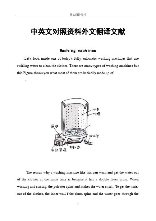
中英文对照资料外文翻译文献Washing machinesLet’s look inside one of today’s fully automatic washing machines that use swirling water to clean the clothes. There are many types of washing machines but this Figure shows you what most of them are basically made up of.。
The reason why a washing machine like this can wash and get the water out of the clothes at the same time is because it has a double layer drum. When washing and rinsing, the pulsator spins and makes the water swirl.. To get the water out of the clothes, the inner wall f the drum spins and the water goes through theholes.These days, the “centrifugal force washing machines” are quite popular. This type of machine does not use a pulsator. Instead, the inner wall spins really quickly. When the drum spins, the dirty clothes get stuck to the wall. The water and detergent also try to escape through the holes of the wall but before they do so, they are forced to escape through the clothes. When this happens, the power of the water and detergent removes the dirt form the clothes. Another good thing about this type of machine is that clothes don’t get tangled up so you don’t have to worry about your clothes getting ripped or damaged.Next, let’s look at some different types of washing machines!Many of you probably think that the water inside washing machines goes round and round. Actually, different washing machines make water flow in different ways.Whirlpool type:This type of washing machine uses a pulsator to force the water to move like a whirlpool inside the Drum. The spinning water forces the dirt out form the clothes inside the machine. Some of the newer models of this type also make the whirlpool move up and down to make it clean clothes even better!Agitator stirring typeThis type of washing machine has something that looks like a propeller at the bottom of the tub. This Propeller spins around and stirs the water. The water then forces the dirt out from the clothes in the machine. The good thing about this type of machine is that clothes do not get tangled up and clothes get evenly washed.Drum type:This type of machine has a drum with many holes in it. There are also protrusions bumps on the wall of the drum. As the drum turns, the clothes arepicked up by the protrusions. When the clothes fall down from the top of the drum through the water, the movement removes dirt from the clothes.Centrifugal force type:As we have said before, the spinning drum pushes the water and detergent out through the wall of the inner drum. The power that comes form spinning the drum is called centrifugal force., which is where the name comes from. The water is forced through the clothes and then the holes in the inner wall. After one cycle, the water is recycled back into the tank and the process starts again. This cycle is what cleans the clothes!In Japan, people first started using machines in 1930. But then the price of a washing machine was so high that most average persons could not buy one for their homes.Looking back now, there was something strange and funny on some of the first versions of the washing machine .The machine had two rollers that were used to sandwich each shirt and other clothes to squeeze the water out of them. The rollers were turned by hand, and in fact, you needed a lot of strength to turn those things! Still, people then thought it was a really neat invention! This type of water squeezer was used for almost 30 years until something new came along. The spin drier that used “centrifugal force” to get most of the water is out of the clothes.In 1953, the nozzle type washing machine was first sold in Japan. This washing machine is like the older brother of the swirling washing machine that you see today. The price of these washing machines was lower and because of this, more people bought them. The first fully automatic washing machine was introduced in 1968, and after that, washing clothes became a lot easier to do!There are a lot of different types of washing machines. What kind of washing machine do you have in your house?Fully automatic:The fully automatic machine has two drum layers that wash, rinse and remove water from clothes together. All you have to do is add detergent and put in dirty clothes and then washing machine will do the rest. There is also a new type of fully automatic washing machine that can dry clothes after they have been washed.Twin tub:This washing machine has one part that dose the washing and another part that does the squeezing. Even though it’s a hassle to take the clothes out and m ove them to other tub, the good thing is that you can wash and squeeze at the same time with one machine.Front loading:The main feature of front loaders is that they use a lot less water than other types. This is the type of Washing machine that dry cleaners use but a lot of people in western countries have this type of washing machine in their homes too.Let’s try to make the best washing machine in the world!We should already thank the scientists that invented the fully automatic washing machine because it makes washing clothes a piece of cake.Scientists are still trying really hard to find ways to make washing machines a lot handier to use for everyone. Some of the things that they are trying to do are to find better ways of making clothes clean and ways to make washing machines last longer. There are washing machines with d trying function today so you don’t even have to hang clothes after words because it dries them automatically! Amazing!Scientists are also trying to find ways to use less water and less detergent in washing machines at present. This is because that it is better to use less water for preserving the environment.What are washing machines of the future going to be like? Maybe there willbe a washing machine that dries and folds your clothes after washing them, or maybe there will be one that will wash your clothes while you are still wearing them! How handy would that be! Remember, if the first washing machine was like a dream to people in the old days, all the dreams you have about washing machines of the future may come true!Now, washing machine is becoming more and more popular. We see the main classification.Washing machine can be divided into automatic type and semi-automatic type two kinds, automatic type washing machine as long as we begin our work proactively set better washing procedure, washing machine began to work until the end without manual intervention. And semi-automatic washing machine washing and dewatering process is divided, is also called the double barrel washing machine, a tong, one takes off a bucket, and put tong inside washing out to artificial add to take off in the barrel dehydration is handled and complete laundry process.Full-automatic washing machine in structure to take off in tong internal bucket suit, two barrels of axis, while working with the clutch to finish washing state and dehydration of the transition of the states, on the key said is automatic washing machine.Full-automatic washing machine press catharsis means to points, can be divided into bunt washer and roll barrel type two kinds of washing machine, From the electric control ways to points, can be divided into mechanical program-controlled type and computer board controls type washing machine two kinds.The cylinder and the pulsator washing machine are now the main two kinds.Pulsator washing machine working principle is to add clothing, then open the inlet valve, choose good bibcock of water level and correct working procedures, switch on the power, closed warehouse door, and safety switch closed at waterlevel, the public internal switch contacts are and dehydration contacts are interlinked, inlet valve electrify water, when the barrel water reaches the specified height, in air pressure under the action of water level switch inside public contacts disconnect dehydration contacts and connect washing contacts, feed valve power to stop water, motor power is switched on, motor started running, and periodically sometimes are turning, sometimes reverse, mutual alternant, driven by clutch BoLun using the same cycle are turning, inversion, with a certain speed rotating BoLun can drive inside bucket of water and clothing, clothing rotating water formed in the mutual friction and reach the purpose of laundry. When washing process is completed, drainage electromagnetic valve electrify work, drain valve is opened, inside bucket of water exudes, and linkage shaft also the clutch from washing state switch to dehydration state, when drainage is completed, atmospheric pressure drop and inside bucket of water level switch public contacts reset through dehydration contacts, drainage electromagnetic valve keep electrify state, motor driven off running electrify bucket high-speed and jilt dry clothing, laundry program after washing machine disconnect hydropower and stop. As for intermediate process of how many times, laundry to wash the length of time, by process control.Roller-type washing machine of the principle and Pulsator washing machine are basic similar. But 110mm drum machine it no clutch variable speed, but its motor is double-speed motor, so when washing machine work in washing state, program-controlled device connected motor washing low-speed windings, motor speed slow, working on dehydration, when they connect dehydration modalhigh-speed windings, motor high-speed operation, this process is programmed through the device and motor to work together to finish.To sum up, the role of these two kinds of washing machine is same, butdifferent implementation, each has his strong point, Pulsator washing machine is simulated handmade kneaded action to work, 110mm drum type washing machine is by gravity inertial function to finish our work, they realize washing and dewatering way also have different features, Pulsator washing machine to wear clothes is relatively large, but detergents degree is higher, 110mm drum machine for clothing wear small, but detergents degrees, but lower than Pulsator washing machine to save water.So far, washing machine is still towards a higher requirements development.译文:洗衣机来看一下涡流式全自动洗衣机的构造。
外文翻译--实际中的谐波和无功补偿
附录1:外文翻译及资料A1.1实际中的谐波和无功补偿1.总述谐波在全世界的公共和工业网络中呈现一种增长的趋势。
这很明显的和工业和商业大厦中用到的非线性装载和设备有关。
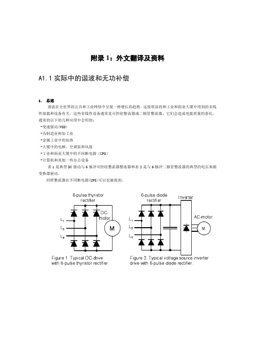
这些非线性设备通常是可控硅整流器或二极管整流器,它们会造成电能质量的恶化,通常的以下的几种应用中会用到:-变速驱动(VSD)-为制造业和加工业-金属工业中的加热-大厦中的电梯、空调泵和风扇-工业和商业大厦中的不间断电源(UPS)-计算机和其他一些办公设备表1是典型DC驱动与6脉冲可控硅整流器整流器和表2是与6脉冲二极管整流器的典型的电压来源变换器驱动。
同样整流器在不同断电源(UPS)可以也被找到。
图3.用于开关方式电源的阶段整流器。
在表3是用于开关方式电源的带电容的阶段整流器。
这种电源是用途广泛在计算机,显示器和在许多其他电子设备。
整流器产生在谐波指令和频率下满足条件的谐波电流: 1±∙==p k f f n fn (1)这里:n f =谐波电流的频率f f =系统的基础频率n =谐波的指令k =1、2、3…p =整流器的脉冲数如果整流器被连接入大的总线,则谐波电流的振幅可以被计算如下: n l l n 1= (2)这里: n I =谐波电流的振幅‘n ’1I =整流器的基础电流n =谐波指令数 然而在真正的电网谐波电流比计算可能有比上面惯例(2)更高的振幅。
在下个章节有另外种类一些被测量的谐波电流整流器。
1.1在真正电网中的谐波电流表4是根本被测量的交流边,并且谐波电流直流驱动与它的装载信息。
能被看见第5谐波在这种情况下是28%对根本性的632A ,而它的根据惯例2的理论价值是20%。
图4 是带高负荷的直流驱动中的基波和谐波电流图 5 是低负荷直流驱动中的基波和谐波电流在表5有与表4一样,都是直流驱动,但是现有更低的负载,。
然而增加谐波的百分比之后基波电流从2261A被减少到1255A,例如第5谐波电流现在是基波电流的41%相当于515A.但是值得注意的是,谐波电流的绝对值是高在高装载情况之下。
电力系统英文单词
电力系统powersystem发电机generator励磁excitation励磁器excitor电压voltage电流current升压变压器step-uptransformer母线bus变压器transformer空载损耗no-loadloss铁损ironloss铜损copperloss空载电流no-loadcurrent有功损耗activeloss无功损耗reactiveloss输电系统powertransmissionsystem 高压侧highside输电线transmissionline高压highvoltage低压lowvoltage中压middlevoltage功角稳定anglestability稳定stability电压稳定voltagestability暂态稳定transientstability 电厂powerplant能量输送powertransfer交流AC直流DC电网powersystem落点droppoint开关站switchstation调节regulation高抗highvoltageshuntreactor 并列的apposable裕度margin故障fault三相故障threephasefault 分接头tap切机generatortriping高顶值highlimitedvalue 静态staticstate动态dynamicstate机端电压控制AVR电抗reactance电阻resistance功角powerangle有功功率activepower电容器Capacitor电抗器Reactor断路器Breaker电动机motor功率因数power-factor定子stator阻抗impedance功角power-angle电压等级voltagegrade有功负载:activeloadPLoad无功负载reactiveload档位tapposition电阻resistor电抗reactance电导conductance电纳susceptance上限upperlimit下限lowerlimit正序阻抗positivesequenceimpedance 负序阻抗negativesequenceimpedance 零序阻抗zerosequenceimpedance无功功率reactivepower功率因数powerfactor无功电流reactivecurrent斜率slope额定rating变比ratio参考值referencevalue电压互感器PT分接头tap仿真分析simulationanalysis 下降率drooprate传递函数transferfunction框图blockdiagram受端receive-side同步synchronization保护断路器circuitbreaker摇摆swing阻尼damping无刷直流电机BruslessDCmotor 刀闸隔离开关Isolator机端generatorterminal变电站transformersubstation永磁同步电机Permanent-magnetSynchronismMotor异步电机AsynchronousMotor三绕组变压器three-columntransformerThrClnTrans 双绕组变压器double-columntransformerDblClmnTrans 固定串联电容补偿fixedseriescapacitorcompensation 双回同杆并架double-circuitlinesonthesametower单机无穷大系统onemachine-infinitybussystem励磁电流Magnetizingcurrent补偿度degreeofcompensation电磁场:Electromagneticfields失去同步lossofsynchronization装机容量installedcapacity无功补偿reactivepowercompensation故障切除时间faultclearingtime极限切除时间criticalclearingtime强行励磁reinforcedexcitation并联电容器shuntcapacitor<下降特性droopcharacteristics线路补偿器LDClinedropcompensation电机学ElectricalMachinery自动控制理论AutomaticControlTheory电磁场ElectromagneticField微机原理PrincipleofMicrocomputer电工学Electrotechnics电路原理Principleofcircuits电机学ElectricalMachinery电力系统稳态分析Steady-StateAnalysisofPowerSystem电力系统暂态分析Transient-StateAnalysisofPowerSystem电力系统继电保护原理PrincipleofElectricalSystem'sRelayProtection电力系统元件保护原理ProtectionPrincipleofPowerSystem'sElement 电力系统内部过电压PastVoltagewithinPowersystem模拟电子技术基础BasisofAnalogueElectronicTechnique数字电子技术DigitalElectricalTechnique电路原理实验电气工程讲座Lecturesonelectricalpowerproduction电力电子基础Basicfundamentalsofpowerelectronics高电压工程Highvoltageengineering电子专题实践Topicsonexperimentalprojectofelectronics 电气工程概论Introductiontoelectricalengineering电子电机集成系统Electronicmachinesystem电力传动与控制ElectricalDriveandControl电力系统继电保护PowerSystemRelayingProtection主变压器maintransformer升压变压器step-uptransformer降压变压器step-downtransformer工作变压器operatingtransformer备用变压器公用变压器commontransformer三相变压器three-phasetransformer单相变压器single-phasetransformer带负荷调压变压器on-loadregulatingtransformer 变压器铁芯transformercore变压器线圈transformercoil变压器绕组transformerwinding变压器油箱transformeroiltank变压器外壳变压器风扇transformerfan变压器油枕transformeroilconservator∽drum 变压器额定电压transformerretedvoltage变压器额定电流transformerretedcurrent变压器调压范围transformervoltageregulationrage 配电设备powerdistributionequipmentSF6断路器SF6circuitbreaker开关switch按钮button隔离开关isolator,disconnector 真空开关vacuumswitch刀闸开关knife-switch接地刀闸earthingknife-switch 电气设备electricalequipment 变流器currentconverter电流互感器currenttransformer电压互感器voltagetransformer电源powersource交流电源ACpowersource 直流电源DCpowersource 工作电源operatingsource 备用电源Standbysource 强电strongcurrent 弱电weakcurrent继电器relay信号继电器signalrelay电流继电器currentrelay电压继电器voltagerelay跳闸继电器trippingrelay合闸继电器closingrelay中间继电器intermediaterelay时间继电器timerelay零序电压继电器zero-sequencevoltagerelay 差动继电器differentialrelay闭锁装置lockingdevice遥控telecontrol遥信telesignalisation遥测telemetering遥调teleregulation断路器breaker,circuitbreaker少油断路器mini-oilbreaker,oil-mini-mumbreaker 高频滤波器high-frequencyfilter组合滤波器combinedfilter常开触点normallyopenedcontaact常闭触点normallyclosedcontaact 并联电容parallelcapacitance保护接地protectiveearthing熔断器cutout,fusiblecutout 电缆cable跳闸脉冲trippingpulse合闸脉冲closingpulse一次电压primaryvoltage二次电压secondaryvoltage并联电容器parallelcapacitor无功补偿器reactivepowercompensationdevice 消弧线圈arc-suppressingcoil母线Bus,busbar三角接法deltaconnection星形接法Wyeconnection原理图schematicdiagram一次系统图primarysystemdiagram二次系统图secondarysystemdiagram两相短路two-phaseshortcircuit三相短路three-phaseshortcircuit单相接地短路single-phasegroundshortcircuit短路电流计算calculationofshortcircuitcurrent 自动重合闸automaticreclosing高频保护high-freqencyprotection距离保护distanceprotection横差保护transversedifferentialprotection 纵差保护longitudinaldifferentialprotection 线路保护lineprotection过电压保护over-voltageprotection母差保护busdifferentialprotection 瓦斯保护Buchholtzprotection变压器保护transformerprotection电动机保护motorprotection远方控制remotecontrol用电量powerconsumption载波carrier故障fault选择性selectivity速动性speed灵敏性sensitivity可靠性reliability电磁型继电器electromagnetic无时限电流速断保护instantaneouslyover-currentprotection 跳闸线圈tripcoil工作线圈operatingcoil制动线圈retraintcoil主保护mainprotection后备保护back-upprotection定时限过电流保护definitetimeover-currentprotection 三段式电流保护thecurrentprotectionwiththreestages 反时限过电流保护inversetimeover-currentprotection 方向性电流保护thedirectionalcurrentprotection零序电流保护zero-sequencecurrentprotection阻抗impedance微机保护MicroprocessorProtection。
电气毕业设计用外文翻译(中英文对照)
The Transformer on load ﹠Introduction to DC Machine sThe Transformer on loadIt has been shown that a primary input voltage 1V can be transformed to any desired open-circuit secondary voltage 2E by a suitable choice of turns ratio. 2E is available for circulating a load current impedance. For the moment, a lagging power factor will be considered. The secondary current and the resulting ampere-turns 22N I will change the flux, tending to demagnetize the core, reduce m Φ and with it 1E . Because the primary leakage impedance drop is so low, a small alteration to 1E will cause an appreciable increase of primary current from 0I to a new value of 1I equal to ()()i jX R E V ++111/. The extra primary current and ampere-turns nearly cancel the whole of the secondary ampere-turns. This being so , the mutual flux suffers only a slight modification and requires practically the same net ampere-turns 10N I as on no load. The total primary ampere-turns are increased by an amount 22N I necessary to neutralize the same amount of secondary ampere-turns. In the vector equation , 102211N I N I N I =+; alternatively, 221011N I N I N I -=. At full load, the current 0I is only about 5% of the full-load current and so 1I is nearly equal to 122/N N I . Because in mind that 2121/N N E E =, the input kV A which is approximately 11I E is also approximately equal to the output kV A, 22I E .The physical current has increased, and with in the primary leakage flux to which it is proportional. The total flux linking the primary ,111Φ=Φ+Φ=Φm p , is shown unchanged because the total back e.m.f.,(dt d N E /111Φ-)is still equal and opposite to 1V . However, there has been a redistribution of flux and the mutual component has fallen due to the increase of 1Φ with 1I . Although the change is small, the secondary demand could not be met without a mutual flux and e.m.f. alteration to permit primary current to change. The net flux s Φlinking the secondary winding has been further reduced by the establishment of secondary leakage flux due to 2I , and this opposes m Φ. Although m Φ and2Φ are indicated separately , they combine to one resultant in the core which will be downwards at the instant shown. Thus the secondary terminal voltage is reduced to dt d N V S /22Φ-= which can be considered in two components, i.e. dt d N dt d N V m //2222Φ-Φ-=or vectorially 2222I jX E V -=. As for the primary, 2Φ is responsible for a substantially constant secondaryleakage inductance 222222/Λ=ΦN i N . It will be noticed that the primary leakage flux is responsiblefor part of the change in the secondary terminal voltage due to its effects on the mutual flux. The two leakage fluxes are closely related; 2Φ, for example, by its demagnetizing action on m Φ has caused the changes on the primary side which led to the establishment of primary leakage flux.If a low enough leading power factor is considered, the total secondary flux and the mutual flux are increased causing the secondary terminal voltage to rise with load. p Φ is unchanged in magnitude from the no load condition since, neglecting resistance, it still has to provide a total back e.m.f. equal to 1V . It is virtually the same as 11Φ, though now produced by the combined effect of primary and secondary ampere-turns. The mutual flux must still change with load to give a change of 1E and permit more primary current to flow. 1E has increased this time but due to the vector combination with 1V there is still an increase of primary current.Two more points should be made about the figures. Firstly, a unity turns ratio has been assumed for convenience so that '21E E =. Secondly, the physical picture is drawn for a different instant of time from the vector diagrams which show 0=Φm , if the horizontal axis is taken as usual, to be the zero time reference. There are instants in the cycle when primary leakage flux is zero, when the secondary leakage flux is zero, and when primary and secondary leakage flux is zero, and when primary and secondary leakage fluxes are in the same sense.The equivalent circuit already derived for the transformer with the secondary terminals open, can easily be extended to cover the loaded secondary by the addition of the secondary resistance and leakage reactance.Practically all transformers have a turns ratio different from unity although such an arrangement issometimes employed for the purposes of electrically isolating one circuit from another operating at the same voltage. To explain the case where 21N N ≠ the reaction of the secondary will be viewed from the primary winding. The reaction is experienced only in terms of the magnetizing force due to the secondary ampere-turns. There is no way of detecting from the primary side whether 2I is large and 2N small or vice versa, it is the product of current and turns which causes the reaction. Consequently, a secondary winding can be replaced by any number of different equivalent windings and load circuits which will give rise to an identical reaction on the primary .It is clearly convenient to change the secondary winding to an equivalent winding having the same number of turns 1N as the primary.With 2N changes to 1N , since the e.m.f.s are proportional to turns, 2212)/('E N N E = which is the same as 1E .For current, since the reaction ampere turns must be unchanged 1222'''N I N I = must be equal to 22N I .i.e. 2122)/(I N N I =.For impedance , since any secondary voltage V becomes V N N )/(21, and secondary current I becomes I N N )/(12, then any secondary impedance, including load impedance, must become I V N N I V /)/('/'221=. Consequently, 22212)/('R N N R = and 22212)/('X N N X = .If the primary turns are taken as reference turns, the process is called referring to the primary side. There are a few checks which can be made to see if the procedure outlined is valid.For example, the copper loss in the referred secondary winding must be the same as in the original secondary otherwise the primary would have to supply a different loss power. ''222R I must be equal to 222R I . )222122122/()/(N N R N N I ∙∙ does in fact reduce to 222R I .Similarly the stored magnetic energy in the leakage field )2/1(2LI which is proportional to 22'X I will be found to check as ''22X I . The referred secondary 2212221222)/()/(''I E N N I N N E I E kVA =∙==.The argument is sound, though at first it may have seemed suspect. In fact, if the actual secondarywinding was removed physically from the core and replaced by the equivalent winding and load circuit designed to give the parameters 1N ,'2R ,'2X and '2I , measurements from the primary terminals would be unable to detect any difference in secondary ampere-turns, kVA demand or copper loss, under normal power frequency operation.There is no point in choosing any basis other than equal turns on primary and referred secondary, but it is sometimes convenient to refer the primary to the secondary winding. In this case, if all the subscript 1’s are interchanged for the subscript 2’s, the necessary referring constants are easily found; e.g. 2'1R R ≈,21'X X ≈; similarly 1'2R R ≈ and 12'X X ≈.The equivalent circuit for the general case where 21N N ≠ except that m r has been added to allow for iron loss and an ideal lossless transformation has been included before the secondary terminals to return '2V to 2V .All calculations of internal voltage and power losses are made before this ideal transformation is applied. The behaviour of a transformer as detected at both sets of terminals is the same as the behaviour detected at the corresponding terminals of this circuit when the appropriate parameters are inserted. The slightly different representation showing the coils 1N and 2N side by side with a core in between is only used for convenience. On the transformer itself, the coils are , of course , wound round the same core.Very little error is introduced if the magnetising branch is transferred to the primary terminals, but a few anomalies will arise. For example ,the current shown flowing through the primary impedance is no longer the whole of the primary current. The error is quite small since 0I is usually such a small fraction of 1I . Slightly different answers may be obtained to a particular problem depending on whether or not allowance is made for this error. With this simplified circuit, the primary and referred secondary impedances can be added to give: 221211)/(Re N N R R += and 221211)/(N N X X Xe +=It should be pointed out that the equivalent circuit as derived here is only valid for normal operation at power frequencies; capacitance effects must be taken into account whenever the rate of change of voltage would give rise to appreciable capacitance currents, dt CdV I c /=. They are important at high voltages and at frequencies much beyond 100 cycles/sec. A further point is not theonly possible equivalent circuit even for power frequencies .An alternative , treating the transformer as a three-or four-terminal network, gives rise to a representation which is just as accurate and has some advantages for the circuit engineer who treats all devices as circuit elements with certain transfer properties. The circuit on this basis would have a turns ratio having a phase shift as well as a magnitude change, and the impedances would not be the same as those of the windings. The circuit would not explain the phenomena within the device like the effects of saturation, so for an understanding of internal behaviour .There are two ways of looking at the equivalent circuit:(a) viewed from the primary as a sink but the referred load impedance connected across '2V ,or (b) viewed from the secondary as a source of constant voltage 1V with internal drops due to 1Re and 1Xe . The magnetizing branch is sometimes omitted in this representation and so the circuit reduces to a generator producing a constant voltage 1E (actually equal to 1V ) and having an internal impedance jX R + (actually equal to 11Re jXe +).In either case, the parameters could be referred to the secondary winding and this may save calculation time .The resistances and reactances can be obtained from two simple light load tests.Introduction to DC MachinesDC machines are characterized by their versatility. By means of various combination of shunt, series, and separately excited field windings they can be designed to display a wide variety of volt-ampere or speed-torque characteristics for both dynamic and steadystate operation. Because of the ease with which they can be controlled , systems of DC machines are often used in applications requiring a wide range of motor speeds or precise control of motor output.The essential features of a DC machine are shown schematically. The stator has salient poles and is excited by one or more field coils. The air-gap flux distribution created by the field winding is symmetrical about the centerline of the field poles. This axis is called the field axis or direct axis.As we know , the AC voltage generated in each rotating armature coil is converted to DC in the external armature terminals by means of a rotating commutator and stationary brushes to which the armature leads are connected. The commutator-brush combination forms a mechanical rectifier,resulting in a DC armature voltage as well as an armature m.m.f. wave which is fixed in space. The brushes are located so that commutation occurs when the coil sides are in the neutral zone , midway between the field poles. The axis of the armature m.m.f. wave then in 90 electrical degrees from the axis of the field poles, i.e., in the quadrature axis. In the schematic representation the brushes are shown in quarature axis because this is the position of the coils to which they are connected. The armature m.m.f. wave then is along the brush axis as shown.. (The geometrical position of the brushes in an actual machine is approximately 90 electrical degrees from their position in the schematic diagram because of the shape of the end connections to the commutator.)The magnetic torque and the speed voltage appearing at the brushes are independent of the spatial waveform of the flux distribution; for convenience we shall continue to assume a sinusoidal flux-density wave in the air gap. The torque can then be found from the magnetic field viewpoint.The torque can be expressed in terms of the interaction of the direct-axis air-gap flux per pole d Φ and the space-fundamental component 1a F of the armature m.m.f. wave . With the brushes in the quadrature axis, the angle between these fields is 90 electrical degrees, and its sine equals unity. For a P pole machine 12)2(2a d F P T ϕπ= In which the minus sign has been dropped because the positive direction of the torque can be determined from physical reasoning. The space fundamental 1a F of the sawtooth armature m.m.f. wave is 8/2π times its peak. Substitution in above equation then gives a d a a d a i K i mPC T ϕϕπ==2 Where a i =current in external armature circuit;a C =total number of conductors in armature winding;m =number of parallel paths through winding;And mPC K a a π2=Is a constant fixed by the design of the winding.The rectified voltage generated in the armature has already been discussed before for an elementary single-coil armature. The effect of distributing the winding in several slots is shown in figure ,in which each of the rectified sine waves is the voltage generated in one of the coils, commutation taking place at the moment when the coil sides are in the neutral zone. The generated voltage as observed from the brushes is the sum of the rectified voltages of all the coils in series between brushes and is shown by the rippling line labeled a e in figure. With a dozen or so commutator segments per pole, the ripple becomes very small and the average generated voltage observed from the brushes equals the sum of the average values of the rectified coil voltages. The rectified voltage a e between brushes, known also as the speed voltage, is m d a m d a a W K W mPC e ϕϕπ==2 Where a K is the design constant. The rectified voltage of a distributed winding has the same average value as that of a concentrated coil. The difference is that the ripple is greatly reduced.From the above equations, with all variable expressed in SI units:m a a Tw i e =This equation simply says that the instantaneous electric power associated with the speed voltage equals the instantaneous mechanical power associated with the magnetic torque , the direction of power flow being determined by whether the machine is acting as a motor or generator.The direct-axis air-gap flux is produced by the combined m.m.f. f f i N ∑ of the field windings, the flux-m.m.f. characteristic being the magnetization curve for the particular iron geometry of the machine. In the magnetization curve, it is assumed that the armature m.m.f. wave is perpendicular to the field axis. It will be necessary to reexamine this assumption later in this chapter, where the effects of saturation are investigated more thoroughly. Because the armature e.m.f. is proportional to flux timesspeed, it is usually more convenient to express the magnetization curve in terms of the armature e.m.f. 0a e at a constant speed 0m w . The voltage a e for a given flux at any other speed m w is proportional to the speed,i.e. 00a m m a e w w e Figure shows the magnetization curve with only one field winding excited. This curve can easily be obtained by test methods, no knowledge of any design details being required.Over a fairly wide range of excitation the reluctance of the iron is negligible compared with that of the air gap. In this region the flux is linearly proportional to the total m.m.f. of the field windings, the constant of proportionality being the direct-axis air-gap permeance.The outstanding advantages of DC machines arise from the wide variety of operating characteristics which can be obtained by selection of the method of excitation of the field windings. The field windings may be separately excited from an external DC source, or they may be self-excited; i.e., the machine may supply its own excitation. The method of excitation profoundly influences not only the steady-state characteristics, but also the dynamic behavior of the machine in control systems.The connection diagram of a separately excited generator is given. The required field current is a very small fraction of the rated armature current. A small amount of power in the field circuit may control a relatively large amount of power in the armature circuit; i.e., the generator is a power amplifier. Separately excited generators are often used in feedback control systems when control of the armature voltage over a wide range is required. The field windings of self-excited generators may be supplied in three different ways. The field may be connected in series with the armature, resulting in a shunt generator, or the field may be in two sections, one of which is connected in series and the other in shunt with the armature, resulting in a compound generator. With self-excited generators residual magnetism must be present in the machine iron to get the self-excitation process started.In the typical steady-state volt-ampere characteristics, constant-speed primemovers being assumed. The relation between the steady-state generated e.m.f. a E and the terminal voltage t V isa a a t R I E V -=Where a I is the armature current output and a R is the armature circuit resistance. In a generator, a E is large than t V ; and the electromagnetic torque T is a countertorque opposing rotation.The terminal voltage of a separately excited generator decreases slightly with increase in the load current, principally because of the voltage drop in the armature resistance. The field current of a series generator is the same as the load current, so that the air-gap flux and hence the voltage vary widely with load. As a consequence, series generators are not often used. The voltage of shunt generators drops off somewhat with load. Compound generators are normally connected so that the m.m.f. of the series winding aids that of the shunt winding. The advantage is that through the action of the series winding the flux per pole can increase with load, resulting in a voltage output which is nearly constant. Usually, shunt winding contains many turns of comparatively heavy conductor because it must carry the full armature current of the machine. The voltage of both shunt and compound generators can be controlled over reasonable limits by means of rheostats in the shunt field. Any of the methods of excitation used for generators can also be used for motors. In the typical steady-state speed-torque characteristics, it is assumed that the motor terminals are supplied from a constant-voltage source. In a motor the relation between the e.m.f. a E generated in the armature and the terminal voltage t V isa a a t R I E V +=Where a I is now the armature current input. The generated e.m.f. a E is now smaller than the terminal voltage t V , the armature current is in the opposite direction to that in a motor, and the electromagnetic torque is in the direction to sustain rotation ofthe armature.In shunt and separately excited motors the field flux is nearly constant. Consequently, increased torque must be accompanied by a very nearly proportional increase in armature current and hence by a small decrease in counter e.m.f. to allow this increased current through the small armature resistance. Since counter e.m.f. is determined by flux and speed, the speed must drop slightly. Like the squirrel-cage induction motor ,the shunt motor is substantially a constant-speed motor having about 5 percent drop in speed from no load to full load. Starting torque and maximum torque are limited by the armature current that can be commutated successfully.An outstanding advantage of the shunt motor is ease of speed control. With a rheostat in the shunt-field circuit, the field current and flux per pole can be varied at will, and variation of flux causes the inverse variation of speed to maintain counter e.m.f. approximately equal to the impressed terminal voltage. A maximum speed range of about 4 or 5 to 1 can be obtained by this method, the limitation again being commutating conditions. By variation of the impressed armature voltage, very wide speed ranges can be obtained.In the series motor, increase in load is accompanied by increase in the armature current and m.m.f. and the stator field flux (provided the iron is not completely saturated). Because flux increases with load, speed must drop in order to maintain the balance between impressed voltage and counter e.m.f.; moreover, the increase in armature current caused by increased torque is smaller than in the shunt motor because of the increased flux. The series motor is therefore a varying-speed motor with a markedly drooping speed-load characteristic. For applications requiring heavy torque overloads, this characteristic is particularly advantageous because the corresponding power overloads are held to more reasonable values by the associated speed drops. Very favorable starting characteristics also result from the increase in flux with increased armature current.In the compound motor the series field may be connected either cumulatively, so that its.m.m.f.adds to that of the shunt field, or differentially, so that it opposes. The differential connection is very rarely used. A cumulatively compounded motor hasspeed-load characteristic intermediate between those of a shunt and a series motor, the drop of speed with load depending on the relative number of ampere-turns in the shunt and series fields. It does not have the disadvantage of very high light-load speed associated with a series motor, but it retains to a considerable degree the advantages of series excitation.The application advantages of DC machines lie in the variety of performance characteristics offered by the possibilities of shunt, series, and compound excitation. Some of these characteristics have been touched upon briefly in this article. Still greater possibilities exist if additional sets of brushes are added so that other voltages can be obtained from the commutator. Thus the versatility of DC machine systems and their adaptability to control, both manual and automatic, are their outstanding features.负载运行的变压器及直流电机导论负载运行的变压器通过选择合适的匝数比,一次侧输入电压1V 可任意转换成所希望的二次侧开路电压2E 。
电力中英词汇
电力词汇(中英文对照)标准的机组数据显示(Standard Measurement And Display Data)负载电流百分比显示Percentage of Current load(%)单相/三相电压Voltage by One/Three Phase (Volt.)每相电流Current by Phase (AMP)千伏安Apparent Power (KVA)中线电流Neutral Current (N Amp)功率因数Power Factor (PF)频率Frequency(HZ)千瓦Active Power (KW)千阀Reactive Power (KVAr)最高/低电压及电流Max/Min. Current and Voltage输非法关键字瓦/兆瓦小时Output kWh/MWh运行转速Running RPM机组运行正常Normal Running超速故障停机Overspeed Shutdowns低油压故障停机Low Oil Pressure Shutdowns高水温故障停机High Coolant Temperature Shutdowns起动失败停机Fail to Start Shutdowns冷却水温度表Coolant Temperature Gauge机油油压表Oil Pressure Gauge电瓶电压表Battery Voltage Meter机组运行小时表Genset Running Hour Meter怠速-快速运行选择键Idle Run –Normal Run Selector Switch运行-停机-摇控启动选择键Local Run-Stop-Remote Starting Selector Switch 其它故障显示及输入Other Common Fault Alarm Display and电力行波词汇行波travelling wave模糊神经网络fuzzy-neural network神经网络neural network模糊控制fuzzy control研究方向research direction副教授associate professor电力系统the electrical power system大容量发电机组large capacity generating set输电距离electricity transmission超高压输电线supervltage transmission power line投运commissioning行波保护Traveling wave protection自适应控制方法adaptive control process动作速度speed of action行波信号travelling wave signal测量信号measurement signal暂态分量transient state component非线性系统nonlinear system高精度high accuracy自学习功能selflearning function抗干扰能力antijamming capability自适应系统adaptive system行波继电器travelling wave relay输电线路故障transmission line malfunction仿真simulation算法algorithm电位electric potential短路故障short trouble子系统subsystem大小相等,方向相反equal and opposite in direction电压源voltage source故障点trouble spot等效于equivalent暂态行波transient state travelling wave偏移量side-play mount电压electric voltage附加系统add-ons system波形waveform工频power frequency延迟变换delayed transformation延迟时间delay time减法运算subtraction相减运算additive operation求和器summator模糊规则fuzzy rule参数值parameter values可靠动作action message等值波阻抗equivalent value wave impedance附加网络additional network修改的modified反传算法backpropagation algorithm隶属函数membership function模糊规则fuzzy rule模糊推理fuzzy reasoning样本集合sample set给定的given模糊推理矩阵fuzzy reasoning matrix采样周期sampling period三角形隶属度函数Triangle-shape grade of membership function 负荷状态load conditions区内故障troubles inside the sample space门槛值threshold level采样频率sampling frequency全面地all sidedly样本空间sample space误动作malfunction保护特性protection feature仿真数据simulation data灵敏性sensitivity小波变换wavelet transformation神经元neuron谐波电流harmonic current电力系统自动化power system automation继电保护relaying protection中国电力China Power学报journal初探primary exploration(1)元件设备三绕组变压器:three-column transformer ThrClnTrans双绕组变压器:double-column transformer DblClmnTrans 电容器:Capacitor并联电容器:shunt capacitor电抗器:Reactor母线:Busbar输电线:TransmissionLine发电厂:power plant断路器:Breaker刀闸(隔离开关):Isolator分接头:tap电动机:motor(2)状态参数有功:active power无功:reactive power电流:current容量:capacity电压:voltage档位:tap position有功损耗:reactive loss无功损耗:active loss功率因数:power-factor功率:power功角:power-angle电压等级:voltage grade空载损耗:no-load loss铁损:iron loss铜损:copper loss空载电流:no-load current阻抗:impedance正序阻抗:positive sequence impedance负序阻抗:negative sequence impedance零序阻抗:zero sequence impedance电阻:resistor电抗:reactance电导:conductance电纳:susceptance无功负载:reactive load 或者QLoad有功负载: active load PLoad遥测:YC(telemetering)遥信:YX励磁电流(转子电流):magnetizing current定子:stator功角:power-angle上限:upper limit下限:lower limit并列的:apposable高压: high voltage低压:low voltage中压:middle voltage电力系统power system发电机generator励磁excitation励磁器excitor电压voltage电流current母线bus变压器transformer升压变压器step-up transformer高压侧high side输电系统power transmission system输电线transmission line固定串联电容补偿fixed series capacitor compensation 稳定stability电压稳定voltage stability功角稳定angle stability暂态稳定transient stability电厂power plant能量输送power transfer交流AC装机容量installed capacity电网power system落点drop point开关站switch station双回同杆并架double-circuit lines on the same tower 变电站transformer substation补偿度degree of compensation高抗high voltage shunt reactor无功补偿reactive power compensation故障fault调节regulation裕度magin三相故障three phase fault故障切除时间fault clearing time极限切除时间critical clearing time切机generator triping高顶值high limited value强行励磁reinforced excitation线路补偿器LDC(line drop compensation)机端generator terminal静态static (state)动态dynamic (state)单机无穷大系统one machine - infinity bus system 机端电压控制AVR电抗reactance电阻resistance功角power angle有功(功率)active power无功(功率)reactive power功率因数power factor无功电流reactive current下降特性droop characteristics斜率slope额定rating变比ratio参考值reference value电压互感器PT分接头tap下降率droop rate仿真分析simulation analysis传递函数transfer function框图block diagram受端receive-side裕度margin同步synchronization失去同步loss of synchronization 阻尼damping摇摆swing保护断路器circuit breaker电阻:resistance电抗:reactance阻抗:impedance电导:conductance电纳:susceptance导纳:admittance电感:inductance电容: capacitance。
减速器论文中英文对照资料外文翻译文献

减速器论文中英文对照资料外文翻译文献What is a Gearbox?A XXX.1.The n of a Gearbox1) The gearbox ces the speed while increasing the output torque。
The torque output。
is the motor output multiplied by the n。
but it should not exceed the XXX.2) The gearbox also ces the inertia of the load。
which decreases by the square of the n。
Most motors have an inertia value that can be XXX.2.Types of GearboxesCommon gearboxes include bevel gear cers (including parallel-axis bevel gear cers。
worm gear cers。
and cone gear cers)。
ary gear cers。
cycloid cers。
worm gear cers。
XXX.mon Gearboxes1) The main feature of the worm gear cer is its reverse self-locking n。
which can achieve a large n。
The input and output shafts are not on the same axis or in the same plane。
However。
it generally has a large volume。
low n efficiency。
and low n.2) XXX and power。
It has a small size and high n。
(完整word版)电力专业常用英语词汇

网易电力专业英语词汇(较全)1)元件设备三绕组变压器:three-column transformer ThrClnTrans双绕组变压器:double—column transformer DblClmnTrans 电容器:Capacitor并联电容器:shunt capacitor电抗器:Reactor母线:Busbar输电线:TransmissionLine发电厂:power plant断路器:Breaker刀闸(隔离开关):Isolator分接头:tap电动机:motor2)状态参数有功:active power无功:reactive power电流:current容量:capacity电压:voltage档位:tap position有功损耗:reactive loss无功损耗:active loss空载损耗:no—load loss铁损:iron loss铜损:copper loss空载电流:no—load current阻抗:impedance正序阻抗:positive sequence impedance 负序阻抗:negative sequence impedance 零序阻抗:zero sequence impedance无功负载:reactive load 或者QLoad有功负载: active load PLoad遥测:YC(telemetering)遥信:YX励磁电流(转子电流):magnetizing current 定子:stator功角:power-angle上限:upper limit下限:lower limit并列的:apposable高压:high voltage低压:low voltage中压:middle voltage电力系统power system发电机generator励磁excitation励磁器excitor电压voltage电流current母线bus变压器transformer升压变压器step-up transformer高压侧high side输电系统power transmission system输电线transmission line固定串联电容补偿fixed series capacitor compensation 稳定stability电压稳定voltage stability功角稳定angle stability暂态稳定transient stability电厂power plant能量输送power transfer交流AC装机容量installed capacity电网power system落点drop point开关站switch station双回同杆并架double-circuit lines on the same tower 变电站transformer substation补偿度degree of compensation高抗high voltage shunt reactor无功补偿reactive power compensation故障fault调节regulation裕度magin三相故障three phase fault故障切除时间fault clearing time极限切除时间critical clearing time切机generator triping高顶值high limited value强行励磁reinforced excitation线路补偿器LDC(line drop compensation)机端generator terminal静态static (state)动态dynamic (state)单机无穷大系统one machine — infinity bus system 机端电压控制AVR功角power angle有功(功率)active power无功(功率)reactive power功率因数power factor无功电流reactive current下降特性droop characteristics 斜率slope额定rating变比ratio参考值reference value电压互感器PT分接头tap下降率droop rate仿真分析simulation analysis传递函数transfer function框图block diagram受端receive-side裕度margin同步synchronization失去同步loss of synchronization 阻尼damping摇摆swing保护断路器circuit breaker电阻:resistance电抗:reactance阻抗:impedance电导:conductance电纳:susceptance导纳:admittance电感:inductance电容:capacitanceAGC Automatic Generation Control自动发电控制AMR Automatic Message Recording 自动抄表ASS Automatic Synchronized System 自动准同期装置ATS Automatic Transform System 厂用电源快速切换装置AVR Automatic Voltage Regulator 自动电压调节器BCS Burner Control System 燃烧器控制系统BMS Burner Management System 燃烧器管理系统CCS Coordinated Control System 协调控制系统CRMS Control Room Management System 控制室管理系统CRT Cathode Ray Tube 阴极射线管DAS Data Acquisition System 数据采集与处理系统DCS Distributed Control System 分散控制系统DDC Direct Digital Control 直接数字控制(系统)DEH Digital Electronic Hydraulic Control 数字电液(调节系统)DPU Distributed Processing Unit 分布式处理单元EMS Energy Management System 能量管理系统ETS Emergency Trip System 汽轮机紧急跳闸系统EWS Engineering Working Station 工程师工作站FA Feeder Automation 馈线自动化FCS Field bus Control System 现场总线控制系统FSS Fuel Safety System 燃料安全系统FSSS Furnace Safeguard Supervisory System 炉膛安全监控系统GIS Gas Insulated Switchgear 气体绝缘开关设备GPS Global Position System 全球定位系统HCS Hierarchical Control System 分级控制系统LCD Liquid Crystal Display 液晶显示屏LCP Local Control Panel 就地控制柜MCC Motor Control Center (电动机)马达控制中心MCS Modulating Control System 模拟量控制系统MEH Micro Electro Hydraulic Control System 给水泵汽轮机电液控制系统MIS Management Information System 管理信息系统NCS Net Control System 网络监控系统OIS Operator Interface Station 操作员接口站OMS Outage Management System 停电管理系统PID Proportion Integration Differentiation 比例积分微分PIO Process inputOutput 过程输入输出(通道)PLC Programmable Logical Controller 可编程逻辑控制器PSS Power System Stabilizator 电力系统稳定器SCADA Supervisory Control And Data Acquisition 数据采集与监控系统SCC Supervisory Computer Control 监督控制系统SCS Sequence Control System 顺序(程序)控制系统SIS Supervisory Information System 监控信息系统TDCS(TDC)Total Direct Digital Control 集散控制系统TSI Turbine Supervisory Instrumentation 汽轮机监测仪表UPS Uninterrupted Power Supply 不间断供电专业英语(电力词汇)标准的机组数据显示(Standard Measurement And Display Data) 负载电流百分比显示Percentage of Current load(%)单相/三相电压Voltage by One/Three Phase (Volt.)每相电流Current by Phase (AMP)千伏安Apparent Power (KVA)中线电流Neutral Current (N Amp)功率因数Power Factor (PF)频率Frequency(HZ)千瓦Active Power (KW)千阀Reactive Power (KVAr)最高/低电压及电流Max/Min. Current and Voltage输出千瓦/兆瓦小时Output kWh/MWh运行转速Running RPM机组运行正常Normal Running超速故障停机Overspeed Shutdowns低油压故障停机Low Oil Pressure Shutdowns高水温故障停机High Coolant Temperature Shutdowns起动失败停机Fail to Start Shutdowns冷却水温度表Coolant Temperature Gauge机油油压表Oil Pressure Gauge电瓶电压表Battery Voltage Meter机组运行小时表Genset Running Hour Meter怠速-快速运行选择键Idle Run – Normal Run Selector Switch运行—停机—摇控启动选择键Local Run—Stop-Remote Starting Selector Switch 其它故障显示及输入Other Common Fault Alarm Display and电力行波词汇行波travelling wave模糊神经网络fuzzy—neural network神经网络neural network模糊控制fuzzy control研究方向research direction副教授associate professor电力系统the electrical power system大容量发电机组large capacity generating set输电距离electricity transmission超高压输电线super voltage transmission power line投运commissioning行波保护Traveling wave protection自适应控制方法adaptive control process动作速度speed of action行波信号travelling wave signal测量信号measurement signal暂态分量transient state component非线性系统nonlinear system高精度high accuracy自学习功能self—learning function抗干扰能力anti-jamming capability自适应系统adaptive system行波继电器travelling wave relay输电线路故障transmission line malfunction仿真simulation算法algorithm电位electric potential短路故障short trouble子系统subsystem大小相等,方向相反equal and opposite in direction 电压源voltage source故障点trouble spot等效于equivalent暂态行波transient state travelling wave偏移量side-play mount电压electric voltage附加系统add-ons system波形waveform工频power frequency延迟变换delayed transformation延迟时间delay time减法运算subtraction相减运算additive operation求和器summator模糊规则fuzzy rule参数值parameter values可靠动作action message等值波阻抗equivalent value wave impedance附加网络additional network修改的modified反传算法backpropagation algorithm隶属函数membership function模糊规则fuzzy rule模糊推理fuzzy reasoning模糊推理矩阵fuzzy reasoning matrix样本集合sample set给定的given采样周期sampling period三角形隶属度函数Triangle-shape grade of membership function负荷状态load conditions区内故障troubles inside the sample space门槛值threshold level采样频率sampling frequency全面地all sidedly样本空间sample space误动作malfunction保护特性protection feature仿真数据simulation data灵敏性sensitivity小波变换wavelet transformation神经元neuron谐波电流harmonic current电力系统自动化power system automation继电保护relaying protection中国电力China Power学报journal初探primary exploration电机学 electrical machinery自动控制理论 automatic control theory电磁场 electromagnetic field电磁场与电磁波Electromagnetic Fields & Magnetic Waves微机原理 principle of microcomputer电工学 electrotechnics principle of circuits电力系统稳态分析 steady—state analysis of power system电力系统暂态分析 transient-state analysis of power system电力系统继电保护原理 principle of electrical system's relay protection 电力系统元件保护原理 protection principle of power system 's element 电力系统内部过电压 past voltage within power system模拟电子技术基础 basis of analogue electronic technique数字电子技术 digital electrical technique电路原理实验lab。
配电系统无功补偿装置中英文对照外文翻译文献

中英文对照外文翻译(文档含英文原文和中文翻译)Optimization of reactive power compensation indistribution systemThe reactive power compensation for distribution network,as the supplement of substation compensation can effectively improve the power factor, reduce line loss, improve the end voltage, ensure the quality of power supply, also bring good economic benefits for enterprise, has received extensive attention. The distributed reactive compensation, installing power capacitors on feeders, is the main distribution network compensation mode at home and abroad [1], but different installed location and different installed capacity, the benefit is different. With the application of reactive power compensation distribution increase gradually, how to choose appropriate reactive compensation location and compensation capacity to make the maximum benefit with less cost become people's research target. And the optimization of distributed reactive compensation of distribution network was raised .At present, the decision of the best compensation capacity and the best position in actual distribution reactive compensation, usually in accordance with ideal situations, such as, the reactive load along the road distributed uniformly, increasing, diminishing distribution or as isosceles distribution, and so on [2], [9]. This method has clear results, simple calculation, and has a certain engineering practical value. But the actual reactive load distribution is more complex, which is different from the ideal situation. So, in accordance with ideal situations to premise reactive compensation configuration optimization formula may be not satisfied. To study a more general distributed reactive compensation configuration optimized method is needed.This paper studies several kinds of typical optimal allocation of reactive compensation configuration with ideal load distribution. Then it details the distributed reactive compensation optimized mathematical model,- 11 -which is applied to any load distribution or distribution network structure, and gives the effective algorithm. At last, the paper introduces the practical application of the research of the model and the algorithm.The ideal load distribution is refers to the reactive power load distributed along the line meet a kind of ideal regular distribution, for example, in any point the road reactive load is equal, named uniform distribution, the reactive load from the first end increasing or decreasing, named increasing or decreasing distribution, and so on. This is an abstract of the actual load distribution, and in such a hypothesis premise the analytical expressions of the optimal location and capacity can be deduced, which can get the best reduce loss effect. And the results are showed in Table I and Fig 1, which can be chose in practical projects [3], [4], [6].When the actual power distribution is different from the ideal situation, using the results to guide the reactive compensation configuration, the effect may be not beautiful. It needs to study a more general reactive compensation configuration optimized method.The optimization of distribution network distributed reactive compensation is distributed as a mixed integer nonlinear optimization problems, which is to determine the reactive compensation position and capacity with some constraints [5]. Therefore, the compensation position and capacity are the two decision variables. Its mathematical model is a two layers optimized problem with constraint. First is the capacity optimization at determined location, second is the distribution optimization. Based on the optimization mathematical model and algorithm, the corresponding graphical calculation software has been developed. With the optimization results, some power capacitors are installed on ten lOkV rural feederswhich had lower power factor and higher line loss. And the actual operation showed good effect. As shown in Fig 3 and Table II, it is the optimization of a feeder named CHANG 7.the total length is 22.35 km, the conductor type of trunk line is LGJ-120,with a distribution capacity of 4760 kVA. The active power- 12 -was 1904 kW, and the power factor was 0.83. The objective power factor was set at 0.9, so the reactive compensation total capacity was 358 kvar. The parameters including length and conductor type of each section, nameplate parameters of transformers, and the reactive compensation total capacity were set in the graphical software. Yet, the graph of the feeder had been drawn too. Then the results were marked on the feeder graph automatically, such as Fig. 3.As shown in Table II, theory line loss rate got an obvious 0.4149 percents decrement, if reactive compensation devices were installed. Also, under the condition of total capacity, two installations made 0.007 percent lower than one, and three points installation made 0.0003 percent lower than two. Then more compensation installations got more decrement of theory line loss rate, but the decreasing rate become inconspicuous, In contrast, equipment maintenance cost increased a lot. Therefore, two installations were selected onCHANG 7 feeder at last.This work provides scientific and reasonable theory for reactive power optimization of distribution network, and gives a reference for the distribution network loss calculation. Also, it provides the convenience for improving the quality of voltage, energy saving and improving line loss management level.1) For solving distribution network reactive power optimization problem, this paper puts forward the double optimization mathematical model of distribution network distributed reactive compensation, the inner is compensation capacity optimization, the outer layer is the reactive compensation distribution optimization. The model can do distribution reactive compensation optimization with any load distribution and arbitrary distribution network structure forms.2) By introducing Lagrange multiplier and the necessary condition of extreme, the mixed integer nonlinear optimization problem is deduced to a linear one that can be easily solved by Gaussian elimination method. It is- 13 -very imple and efficient for computer programming.3) The model and the algorithm can give different optimized results and loss reduction for different number of capacitor installation. Engineering practice showed that optimized capacitors installation can make line loss rate get an obvious decrement. This research plays an important role in the actual reactive compensation equipment installation of distribution network and line loss management.Reasonable reactive power sources compensation of rural substations h as been becoming a hot issue since Chinese rural electric network alteration. The principal reactive power compensation mode of rural substations is still using fixed compensation capacitor to control voltage and reactive power at present in China. This compensation mode has some problems. such as capacity adjustment requires manual intervention under power outage, the phenomenon of over and under compensation may always happen, the rate of putting into operation of reactive power compensation is relatively low, and so on . At the same time, there is no sampling function at the primary side of the main transformer because of the special devices in rural substations. In order to realize the objectives that the power factor is not less than 0.95 at primary side and not less than 0.9 at secondary side at the highest load, in this paper,some optimal reactive power control strategies for rural substation were proposed. In accordance with the reactive power flow conditions of the rural distribution network , the pros and cons of two control strategies were analyzed. One of the strategies was sampling at the primary side of the main transformer , the other was sampling at the s econdary side and switching control by power factor of secondary side. After comparison of such analysis, an optimal control strategy was p roposed. The data were sampledin the substation secondary side, then t he sampled data were evaluated in equivalence to the primaryside, and then the power factor assessment criteria of primary side were used t o control capacitor switching . The compensation capacity should be c- 14 -alculatedafter electric motor compensation , transformer compensation an d distributed compensation on distribution line.The sampled values at se condary side and active loss and reactive loss of themaintransformer w ere used to calculate compensation capacity to meet the power factor o bjectives of primary side. Through the example calculation and analysiby Applying actual substation data a result were obtained.The result met ap praisal standards and the power factor of main transformer primary sid e was above 0.95 at the highest load . If the power factor of main tran sformer secondary side was above 0.98 , there was no need to co mpensate for substation . If the power factor of main transformer secondaryside was under 0.97,after the compensation by using the p roposed optimal compensation capacity and the primary side power f actor control method, the power facto r of the main transformer se condary side was not less than0.98 and the primary side reaches 0.95. T hese results show that the proposed optimal control strategy and compe nsation capacity calculation method are feasible, and the research haspra ctical significance of making full use of reactive power supply in rural di stribution network.Optimal allocation of reactive power compensation plays an important role in power system planning and design. However, as a non-linear, larg e scale combinatorial . optimization problem, Conventional methods are not normally appropriate for it.A mathematical model is firstly presented in this paper for comprehensive optimal configuration in distribution feeders based on the analysis of engineering factors of reactive power compensation, whose objective is to minimize the annual expenditure involving the devices investment and the income of energy saving, and satisfy all sorts of operation ,fixing and maintenance constrains . The control variable include the capacitor banks’number and capacity of various compensation schemes. RARW-GA algorithm is adopted to solve this problem.The result of calculation and analysis of BenXi Steel group c orporation power system shows that the proposed method is feasible- 15 -and effective.An improved TS algorithm is put forward on the condition that reactive power compensation location and capacity have been identified in rural distribution lines. The Algorithm is based on capacitor optimal on-off model aimed at a minimum network loss, it can control the capacitor on-off according to the load changing and the system operation status and keep real-time voltage qualified and network loss minimum. A distributed control system is designed by using the algorithm to realize reactive power optimization, which is composed of reactive power optimal terminals and background control center. The terminal is in charge of data collection and transmission, on-off instruction receiving and executing. The control center in in charge of receiving data from every compensation point, calling control algorithm to process data, forming and sending instructions. GPRS technology is adopted to realize the system’s foreground-background communication. The actual application in some experimental networks has proved that the system can realize global optimal control for distribution lines, and is suitable to be widely used in rural distribution network.In order to solve the optimization of distribution reactive compensation point and capacity, a double optimized model is proposed, which is sui able for reactive compensation optimizationwith random load distribution or random network structure. For the compensation position and capacity decision variables, the optimized model is described as two layers of optimization with constraint . The outer one is the capacity optimization at determined location , and the inlayer is the location optimization . By introducing Lagrange multiplier, the mixed integer nonlinear optimization is deduced to a linearone that can be easily solve by Gaussian elimination method. For illustration, an application of ten 10kV rural feeders is utilized to show the feasibility of the double optimized model in solving the optimization of distribution reactive compensation point and capacity. Empirical results show that the model can give the optimized result for different number of capacitor installa-- 16 -tion, and the result with highest line loss decrementwill be used as thefi nal decision.The research provides scientific theoretical basis for Reactive compensation and plays a vital role in reactive compensation equipment installation and line loss management.Taking account of the mutual impacts of distributed generation and reactive power , to determine the optimal position and capacity of the compensation device to be installed , the paper proposed an improved Tabu search algorithm for reactive power optimiza-tion . The voltage q uality is considered of the model using minimum network active power l oss as objective Function . It is achieved by maintaining the whole s ystem power lossa minimum thereby reducing cost allocation. On the ba sis of general Tabu search algorithm , the algorithm used memory gu idance search strategy to focus on searching for a local optimum va lue, avoid a global search blindness . To deal with the neighborhood so lution set properly or save algorithm storage space,some corresponding i mprovments are made, thus, it is easily to stop the iteration of partial optimization and it is more probable to achieve the global optimizationb y use of the improved algorithm.Simulations are carried out on standard IEEE 33 test system and results are presented.SupSuperconducting Magnetic Energy Storage SMES) can inject or absorb real and reactive power to or from a power system at a very fast rate on a repetitive basis. These characteristics make the application of SMES ideal for transmission grid control and stability enhancement. Superconducting Magnetic Energy Storage SMES) is an attractive apparatus for some power system applications because it is capable of leveling load demand with high efficiency, compensating for load changes, maintaining a bus voltage, and stabilizing power swings. Power system stability problems have attracted the attention of power system engineers for several decades. Considerable progress has been made on excitation control, governor control, control by static var compensator, etc. Modern power systems, which are growing in size and complexity, are characterized by long distance bulk power transmissions and- 17 -wide area interconnections.In such power systems, undamped power swings of low frequency can occur. This can be a serious problem since the instability often decreases the power transmission capacity. As a result, the power that can be transmitted in steady state and transient situations is limited. If the limit is exceeded, the generator loses synchronous operation and system instabilities occur. SMES may be an effective means of preventing these instabilities, thereby maximizing power transfer to meet increased load demand. A SMES system can be represented in dynamic simulations as a continuous controllable real and reactive power source. In steady-state simulations, SMES can be represented as a continuous controllable reactive power source since it can continuously operate throughout its range of reactive power. However, the output of real power from a SMES device is limited to the amount of energy stored in the coil. The first objective of this research is to determine the optimal internal control scheme needed to decide the controllable active and reactive power based on active and reactive power demanded by the power system. The second objective is to design and simulate SMES external control models which are dependent on the network configuration. The third objective is to determine how the optimal size of a SMES device varies for a given transient stability disturbance when alternative internal control models and external control models are used.With a big number of electric energy consumers and different characters electric energy quality depends on many factors in the modern power networks. It includes: power networks and working condition factors of consumers. One of them is the possibility of reactive power balances with an important reserve providing after emergency modes on the basic knots of the power system and voltage regulation on all networks.As the length of networks of a power system increases in modern conditions, we can reduce the reactive power streams, as well as operational and capital expenses. Rational voltage mode brings to the front plan the- 18 -technical一economic aspects of the power transmission EFFICIENCY. Analyses and economic calculations show that transferring the reactive power by short length lines means of a high voltage justifies. Therefore in most cases reduction of reactive power to the minimum is very effective for economically when the sources of reactive power settle down near the consumption centers.The increase of consumer loading and its structure qualitative causes considerable increase of reactive power and constant reduction of a power factor in distributed power networks [ 1」.Thus, the tendency of modern power systems development is characterized by one side with the increase of reactive power consumption (in some systems to 1 kVAR/kVt), on the other side with decrease of power plant generators usage expediency and possibility for the reactive power compensation purpose [2-5]. In such conditions reactive power compensation attains a specialurgency. Here the optimization's primary goal is optimum placing of reactive power sources andsupport of a necessary reserve of capacity QreZ for voltage regulation on loading knot. For example, Polish power engineers consider that capacity of compensators should be 50% of the established capacity of generators in power plants. In France, Sweden and Germany the capacity of compensators is 35% of active peak loading, in the USA and Japan this volume is 70%. In different power systems of the USA the established capacity of compensators is 100% of generators capacities [6-11].Reactive power compensation problem is a multidimensional problem on the technical andeconomic aspects and consequently it is resulted with the finding of a global extremum of criterion function with the set of local extreme. In this article the voltage support within the technical restrictions and definition of optimal placing of the reactive power sources with a technique of multi-purpose- 19 -optimization of reactive power in the power system is considered. By the problem consideration as one-target optimization within restrictions the criterion function is a linear combination from several factors. The problem decision is a unique optimum version and has lacks of alternative versions, and there is not dependency of an end result from the initial data.Thus, the purpose of reactive power sources optimal placing in a power system consists ofincrease the quality of voltage in all central points of a network, control the stability of the system, reduce the power losses and capacities in networks. As a result these will increase the economic efficiency in the power system. From the economic efficiency point of view the new compensating units intended for installation should be proved and given corresponding optimum recommendations.1 .Methods and multi-purpose optimization compensations algorithms have been developed with support of a necessary reserve for preservation of normal level of voltage taking into account technical restrictions in knots of an electric network of a power system. Results of computerization to realization have shown speed and high efficiency the developed algorithm providing minimization of losses of active capacity in a net.2. Based on genetic algorithm the power and installation locations of the static capacitor banks with the multicriteria optimization technique has given. In this case, as a criterion of optimality the minimum expenses for the installation and exploitation, the minimization of power losses during the required values of voltage and power factor and maximum saving and the minimum self-payment term are accepted.3. The report of the real electricity network is given for two cases: operation without the CB;with optimal placement of CB. The application of the proposed method can reduce the averagepower losses approximately 13一14% in the electric network.- 20 -配电系统无功补偿装置容量优化配电网无功补偿,作为补充的变电站补偿可以有效地提高功率因数,减少线路损耗,提高末端电压,保证供电质量,也能带来良好的企业的经济效益,已得到泛的注意。
毕业论文外文翻译范例

外文原文(一)Savigny and his Anglo-American Disciple s*M. H. HoeflichFriedrich Carl von Savigny, nobleman, law reformer, champion of the revived German professoriate, and founder of the Historical School of jurisprudence, not only helped to revolutionize the study of law and legal institutions in Germany and in other civil law countries, but also exercised a profound influence on many of the most creative jurists and legal scholars in England and the United States. Nevertheless, tracing the influence of an individual is always a difficult task. It is especially difficult as regards Savigny and the approach to law and legal sources propounded by the Historical School. This difficulty arises, in part, because Savigny was not alone in adopting this approach. Hugo, for instance, espoused quite similar ideas in Germany; George Long echoed many of these concepts in England during the 1850s, and, of course, Sir Henry Sumner Maine also espoused many of these same concepts central to historical jurisprudence in England in the 1860s and 1870s. Thus, when one looks at the doctrinal writings of British and American jurists and legal scholars in the period before 1875, it is often impossible to say with any certainty that a particular idea which sounds very much the sort of thing that might, indeed, have been derived from Savigny's works, was, in fact, so derived. It is possible, nevertheless, to trace much of the influence of Savigny and his legal writings in the United States and in Great Britain during this period with some certainty because so great was his fame and so great was the respect accorded to his published work that explicit references to him and to his work abound in the doctrinal writing of this period, as well as in actual law cases in the courts. Thus, Max Gutzwiller, in his classic study Der einfluss Savignys auf die Entwicklung des International privatrechts, was able to show how Savigny's ideas on conflict of laws influenced such English and American scholars as Story, Phillimore, Burge, and Dicey. Similarly, Andreas Schwarz, in his "Einflusse Deutscher Zivilistik im Auslande," briefly sketched Savigny's influence upon John Austin, Frederick Pollock, and James Bryce. In this article I wish to examine Savigny's influence over a broader spectrum and to draw a picture of his general fame and reputation both in Britain and in the United States as the leading Romanist, legal historian, and German legal academic of his day. The picture of this Anglo-American respect accorded to Savigny and the historical school of jurisprudence which emerges from these sources is fascinating. It sheds light not only upon Savigny’s trans-channel, trans-Atlantic fame, but also upon the extraordinarily*M.H.Hoeflich, Savigny and his Anglo-American Disciples, American Journal of Comparative Law, vol.37, No.1, 1989.cosmopolitan outlook of many of the leading American and English jurists of the time. Of course, when one sets out to trace the influence of a particular individual and his work, it is necessary to demonstrate, if possible, precisely how knowledge of the man and his work was transmitted. In the case of Savigny and his work on Roman law and ideas of historical jurisprudence, there were three principal modes of transmission. First, there was the direct influence he exercised through his contacts with American lawyers and scholars. Second, there was the influence he exercised through his books. Third, there was the influence he exerted indirectly through intermediate scholars and their works. Let us examine each mode separately.I.INFLUENCE OF THE TRANSLATED WORKSWhile American and British interest in German legal scholarship was high in the antebellum period, the number of American and English jurists who could read German fluently was relatively low. Even those who borrowed from the Germans, for instance, Joseph Story, most often had to depend upon translations. It is thus quite important that Savigny’s works were amongst the most frequently translated into English, both in the United States and in Great Britain. His most influential early work, the Vom Beruf unserer Zeitfur Rechtsgeschichte und Gestzgebung, was translated into English by Abraham Hayward and published in London in 1831. Two years earlier the first volume of his History of Roman Law in the Middle Ages was translated by Cathcart and published in Edinburgh. In 1830, as well, a French translation was published at Paris. Sir Erskine Perry's translation of Savigny's Treatise on Possession was published in London in 1848. This was followed by Archibald Brown's epitome of the treatise on possession in 1872 and Rattigan's translation of the second volume of the System as Jural Relations or the Law of Persons in 1884. Guthrie published a translation of the seventh volume of the System as Private International Law at Edinburgh in 1869. Indeed, two English translations were even published in the far flung corners of the British Raj. A translation of the first volume of the System was published by William Holloway at Madras in 1867 and the volume on possession was translated by Kelleher and published at Calcutta in 1888. Thus, the determined English-speaking scholar had ample access to Savigny's works throughout the nineteenth century.Equally important for the dissemination of Savigny's ideas were those books and articles published in English that explained and analyzed his works. A number of these must have played an important role in this process. One of the earliest of these is John Reddie's Historical Notices of the Roman law and of the Progress of its Study in Germany, published at Edinburgh in 1826. Reddie was a noted Scots jurist and held the Gottingen J.U.D. The book, significantly, is dedicated to Gustav Hugo. It is of that genre known as an external history of Roman law-not so much a history of substantive Roman legal doctrine but rather a historyof Roman legal institutions and of the study of Roman law from antiquity through the nineteenth century. It is very much a polemic for the study of Roman law and for the Historical School. It imparts to the reader the excitement of Savigny and his followers about the study of law historically and it is clear that no reader of the work could possibly be left unmoved. It is, in short, the first work of public relations in English on behalf of Savigny and his ideas.Having mentioned Reddie's promotion of Savigny and the Historical School, it is important to understand the level of excitement with which things Roman and especially Roman law were greeted during this period. Many of the finest American jurists were attracted-to use Peter Stein's term-to Roman and Civil law, but attracted in a way that, at times, seems to have been more enthusiastic than intellectual. Similarly, Roman and Civil law excited much interest in Great Britain, as illustrated by the distinctly Roman influence to be found in the work of John Austin. The attraction of Roman and Civil law can be illustrated and best understood, perhaps, in the context of the publicity and excitement in the English-speaking world surrounding the discovery of the only complete manuscript of the classical Roman jurist Gaius' Institutes in Italy in 1816 by the ancient historian and German consul at Rome, B.G. Niebuhr. Niebuhr, the greatest ancient historian of his time, turned to Savigny for help with the Gaius manuscript (indeed, it was Savigny who recognized the manuscript for what it was) and, almost immediately, the books and journals-not just law journals by any means-were filled with accounts of the discovery, its importance to legal historical studies, and, of course, what it said. For instance, the second volume of the American Jurist contains a long article on the civil law by the scholarly Boston lawyer and classicist, John Pickering. The first quarter of the article is a gushing account of the discovery and first publication of the Gaius manuscript and a paean to Niebuhr and Savigny for their role in this. Similarly, in an article published in the London Law Magazine in 1829 on the civil law, the author contemptuously refers to a certain professor who continued to tell his students that the text of Gaius' Institutes was lost for all time. What could better show his ignorance of all things legal and literary than to be unaware of Niebuhr's great discovery?Another example of this reaction to the discovery of the Gaius palimpsest is to be found in David Irving's Introduction to the Study of the Civil Law. This volume is also more a history of Roman legal scholarship and sources than a study of substantive Roman law. Its pages are filled with references to Savigny's Geschichte and its approach clearly reflects the influence of the Historical School. Indeed, Irving speaks of Savigny's work as "one of the most remarkable productions of the age." He must have been truly impressed with German scholarship and must also have been able to convince the Faculty of Advocates, forwhom he was librarian, of the worth of German scholarship, for in 1820 the Faculty sent him to Gottingen so that he might study their law libraries. Irving devotes several pages of his elementary textbook on Roman law to the praise of the "remarkable" discovery of the Gaius palimpsest. He traces the discovery of the text by Niebuhr and Savigny in language that would have befitted an adventure tale. He elaborates on the various labors required to produce a new edition of the text and was particularly impressed by the use of a then new chemical process to make the under text of the palimpsest visible. He speaks of the reception of the new text as being greeted with "ardor and exultation" strong words for those who spend their lives amidst the "musty tomes" of the Roman law.This excitement over the Verona Gaius is really rather strange. Much of the substance of the Gaius text was already known to legal historians and civil lawyers from its incorporation into Justinian's Institutes and so, from a substantive legal perspective, the find was not crucial. The Gaius did provide new information on Roman procedural rules and it did also provide additional information for those scholars attempting to reconstruct pre-Justinianic Roman law. Nevertheless, these contributions alone seem hardly able to justify the excitement the discovery caused. Instead, I think that the Verona Gaius discovery simply hit a chord in the literary and legal community much the same as did the discovery of the Rosetta Stone or of Schliemann’s Troy. Here was a monument of a great civilization brought newly to light and able to be read for the first time in millenia. And just as the Rosetta Stone helped to establish the modern discipline of Egyptology and Schliemann's discoveries assured the development of classical archaeology as a modern academic discipline, the discovery of the Verona Gaius added to the attraction Roman law held for scholars and for lawyers, even amongst those who were not Romanists by profession. Ancillary to this, the discovery and publication of the Gaius manuscript also added to the fame of the two principals involved in the discovery, Niebuhr and Savigny. What this meant in the English-speaking world is that even those who could not or did not wish to read Savigny's technical works knew of him as one of the discoverers of the Gaius text. This fame itself may well have helped in spreading Savigny's legal and philosophical ideas, for, I would suggest, the Gaius "connection" may well have disposed people to read other of Savigny's writings, unconnected to the Gaius, because they were already familiar with his name.Another example of an English-speaking promoter of Savigny is Luther Stearns Cushing, a noted Boston lawyer who lectured on Roman law at the Harvard Law School in 1848-49 and again in 1851- 1852.Cushing published his lectures at Boston in 1854 under the title An Introduction to the Study of Roman Law. He devoted a full chapter to a description of the historical school and to the controversy betweenSavigny and Thibaut over codification. While Cushing attempted to portray fairly the arguments of both sides, he left no doubt as to his preference for Savigny's approach:The labors of the historical school have established an entirely new and distinct era in the study of the Roman jurisprudence; and though these writers cannot be said to have thrown their predecessors into the shade, it seems to be generally admitted, that almost every branch of the Roman law has received some important modification at their hands, and that a knowledge of their writings, to some extent, at least, is essentially necessary to its acquisition.译文(一)萨维尼和他的英美信徒们*M·H·豪弗里奇弗雷德里奇·卡尔·冯·萨维尼出身贵族,是一位出色的法律改革家,也是一位倡导重建德国教授协会的拥护者,还是历史法学派的创建人之一。
电力专业英语(中英文对照表)

电力专业英语(中英文对照表)电力专业英语(1)元件设备三绕组变压器:three-column transformer ThrClnTrans双绕组变压器:double-column transformer DblClmnTrans 电容器:Capacitor并联电容器:shunt capacitor电抗器:Reactor母线:Busbar输电线:TransmissionLine发电厂:power plant断路器:Breaker刀闸(隔离开关):Isolator分接头:tap电动机:motor(2)状态参数有功:active power无功:reactive power电流:current容量:capacity电压:voltage档位:tap position有功损耗:reactive loss无功损耗:active loss功率因数:power-factor功率:power功角:power-angle电压等级:voltage grade空载损耗:no-load loss铁损:iron loss铜损:copper loss空载电流:no-load current阻抗:impedance正序阻抗:positive sequence impedance 负序阻抗:negative sequence impedance 零序阻抗:zero sequence impedance 电阻:resistor电抗:reactance电导:conductance电纳:susceptance无功负载:reactive load 或者QLoad有功负载: active load PLoad遥测:YC(telemetering)遥信:YX励磁电流(转子电流):magnetizing current 定子:stator功角:power-angle上限:upper limit下限:lower limit并列的:apposable高压: high voltage低压:low voltage中压:middle voltage电力系统 power system发电机 generator励磁 excitation励磁器 excitor电压 voltage电流 current母线 bus变压器 transformer升压变压器 step-up transformer高压侧 high side输电系统 power transmission system输电线 transmission line固定串联电容补偿fixed series capacitor compensation 稳定stability电压稳定 voltage stability功角稳定 angle stability暂态稳定 transient stability电厂 power plant能量输送 power transfer交流 AC装机容量 installed capacity电网 power system落点 drop point开关站 switch station双回同杆并架 double-circuit lines on the same tower 变电站transformer substation补偿度 degree of compensation高抗 high voltage shunt reactor无功补偿 reactive power compensation故障 fault调节 regulation裕度 magin三相故障 three phase fault故障切除时间 fault clearing time极限切除时间 critical clearing time切机 generator triping高顶值 high limited value强行励磁 reinforced excitation线路补偿器 LDC(line drop compensation)机端 generator terminal静态 static (state)动态 dynamic (state)单机无穷大系统 one machine - infinity bus system 机端电压控制 AVR电抗 reactance电阻 resistance功角 power angle有功(功率) active power无功(功率) reactive power功率因数 power factor无功电流 reactive current下降特性 droop characteristics斜率 slope额定 rating变比 ratio参考值 reference value电压互感器 PT分接头 tap下降率 droop rate仿真分析 simulation analysis传递函数 transfer function框图 block diagram受端 receive-side裕度 margin同步 synchronization失去同步 loss of synchronization 阻尼 damping摇摆 swing保护断路器 circuit breaker电阻:resistance电抗:reactance阻抗:impedance 电导:conductance 电纳:susceptance 导纳:admittance 电感:inductance 电容: capacitance。
变电站中英文资料对照外文翻译文献综述
变电站中英文资料对照外文翻译文献综述XXXns are an essential part of electrical power systems。
servingas the interface een high-voltage n lines and lower-voltage n lines。
They play a critical role in XXX homes。
businesses。
and industries.Types of nsThere are several types of ns。
including n ns。
n ns。
and customer XXX to the end-users and step down the voltage for n to XXX a single customer or group of customers.XXXns consist of us components。
including transformers。
circuit breakers。
switches。
XXX are used to step up or step down thevoltage of the electricity。
XXX are used to control the flow ofXXX to the system.XXXXXX stages。
including site n。
layout design。
equipment n。
XXX n lines。
land availability。
and environmental ns。
The layout design involves determining the placement of equipment。
XXX appropriate transformers。
circuit breakers。
and other components。
无功补偿节电计算案例中英文版
Plans for saving electricity节电方案计划Today's companies face a wide range of competition, and constantly reduce the power consumption is not only an important way to reduce costs to improve competitiveness over a long period of time, and is the realization of their own is the effective means to make contributions to reduce emissions当今企业面临广泛的竞争,不断降低电力能耗不仅是长期降低成本提高竞争力的重要途径,而且是实现自身为降低排放作贡献的有效手段。
The way of energy saving of enterprises企业电力节能的途径First, because of the power efficiency of the electric power sector, the improvement of power factor can make no work penalty.一是由于电力部门考核的电力效能,即功率因素提高方面,可使无功罚款转变为无功奖励。
Second,The energy saving effect can be about 8 ~ 15% of the compensation of the load on the side of the load二是自身负载侧的无功修正及线损补偿,其节能效果可以达到8~15%左右。
Third,Electric power special aspects: such as load management, may reduce power load peak power 5 ~ 30%, for a lot of electricity companies such as steel mills, a year can save electricity cost millions三是电力能源的特殊方面:比如负荷管理,可能使电力负荷高峰功率降低5~30%,对一个大量用电企业如钢厂,每年可节约用电费用几百万之巨!Fourth,Clean energy saving on electricity, with a focus on the possible power grid harmonic filter, on the basis of conventional energy saving effect, improve skills 3 ~ 50%, especially can improve the reliability of the system四是着力于电力清洁节能,重点是滤除可能存在的电网谐波,可在常规节能效果的基础上,提高技能率3~50%,特别是可以提高系统的可靠性。
电气中英对照

电气名词中英对照三绕组变压器:three-column transformer ThrClnTrans 双绕组变压器:double-column transformer DblClmnTrans 电容器:Capacitor并联电容器:shunt capacitor电抗器:Reactor母线:Busbar输电线:TransmissionLine发电厂:power plant断路器:Breaker刀闸(隔离开关):Isolator分接头:tap电动机:motor(2)状态参数有功:active power无功:reactive power电流:current容量:capacity电压:voltage档位:tap position有功损耗:reactive loss无功损耗:active loss功率因数:power-factor功率:power功角:power-angle电压等级:voltage grade空载损耗:no-load loss铁损:iron loss铜损:copper loss空载电流:no-load current阻抗:impedance正序阻抗:positive sequence impedance 负序阻抗:negative sequence impedance 零序阻抗:zero sequence impedance电阻:resistor电抗:reactance电导:conductance电纳:susceptance无功负载:reactive load 或者QLoad有功负载: active load PLoad遥测:YC(telemetering)遥信:YX励磁电流(转子电流):magnetizing current定子:stator功角:power-angle上限:upper limit下限:lower limit并列的:apposable高压: high voltage低压:low voltage中压:middle voltage电力系统 power system发电机 generator励磁 excitation励磁器 excitor电压 voltage电流 current母线 bus变压器 transformer升压变压器 step-up transformer高压侧 high side输电系统 power transmission system输电线 transmission line固定串联电容补偿fixed series capacitor compensation稳定 stability电压稳定 voltage stability功角稳定 angle stability暂态稳定 transient stability电厂 power plant能量输送 power transfer交流 AC装机容量 installed capacity电网 power system落点 drop point开关站 switch station双回同杆并架 double-circuit lines on the same tower 变电站 transformer substation补偿度 degree of compensation高抗 high voltage shunt reactor无功补偿 reactive power compensation故障 fault调节 regulation裕度 magin三相故障 three phase fault故障切除时间 fault clearing time极限切除时间 critical clearing time切机 generator triping高顶值 high limited value强行励磁 reinforced excitation线路补偿器 LDC(line drop compensation)机端 generator terminal静态 static (state)动态 dynamic (state)单机无穷大系统 one machine - infinity bus system 机端电压控制 AVR电抗 reactance电阻 resistance功角 power angle有功(功率) active power无功(功率) reactive power功率因数 power factor无功电流 reactive current下降特性 droop characteristics斜率 slope额定 rating变比 ratio参考值 reference value电压互感器 PT分接头 tap下降率 droop rate仿真分析 simulation analysis传递函数 transfer function框图 block diagram受端 receive-side裕度 margin同步 synchronization失去同步 loss of synchronization 阻尼 damping摇摆 swing保护断路器 circuit breaker电阻:resistance电抗:reactance阻抗:impedance电导:conductance电纳:susceptance导纳:admittance电感:inductance电容: capacitance。
浅谈无功补偿装置的工作原理及应用外文翻译.
河北科技师范学院外文翻译间歇性混乱运行开关功率变换器院(系、部名称:机电工程学院专业名称:电气工程及其自动化学生姓名:学生学号:指导教师:年月日河北科技师范学院教务处制间歇性混乱运行开关功率变换器在设计和施工过程中开关电源转换器,混乱的操作经常长时间间歇地观察正常运作。
在实践中,这种间歇性混沌操作就可消除融入设计相应的措施来打击假信号的干扰。
在本文中,我们解释导致间歇性混乱以一个受欢迎的形式的切换转换器,即电流型控制开关转换器建立电路模型用于研究现象具有耦合过程,通过伪信号耦合到当前遥感和斜坡补偿电路,导致边坡的调制补偿引起系统变得不稳定断断续续。
我们的分析表明,假信号耦合到斜坡补偿会导致间歇性混乱或次谐波操作。
关键词:开关电源转换器;电流型控制;间歇性混乱1 介绍间歇性混乱已被观察到开关电源。
尤其是当供给不适当保护,防止入侵的假讯号或寄生电感和电路存在,造成不必要的调制基本控制信号。
例如,在一个电流型控制功率转换器,电感电流采样和用于一个内环达到快速瞬态存在寄生电感、电容可能导致穗状或警告闯入的取样电感电流波形。
入侵也可以以不同的形式通过导电或辐射耦合路径。
有时,入侵者(假信号可以住在同一电路板或出席一个接近问题。
在本文中,我们展示了间歇性混乱运行在一个电流型控制开关转换器可适当进行建模和解释适应入侵的假讯号。
便于设计,我们确定临界参数,间歇性混乱操作和描述的方法来计算参数边界,间歇性混乱运行出现。
2概述的操作电流型控制提高转换器电流型控制的操作转换器可以这样描述如图1.指图1和略去了虚假的来源、提高转炉获得其周期切换方式,一个输入输出的作用,并定期重置时,电感电流等于参考水平。
通常,参考水平是衍生自1971年输出反馈在实践中。
此外,补偿斜坡信号强制合并消除固有的电流型变频器的控制。
在实践中,此外,补偿斜坡信号强制合并消除固有的电流型变频器的控制。
通常的排列图1显示的是和一些典型运行波形显示在图2。
无功补偿控制器中英文简介

reactive power auto-compensation controller1. GeneralThe controller is suitable for automatically adjusting of low voltage distribution sytem capacitor compensating device to make power factor get user’s predetermined state, increase service efficiency of power transformer reduce line loss,and inprove the voltage of power supply.2.Normal working and installation conditions2.1 Ambient temperature: -25℃~ +55℃2.2 Relative humidity: 40℃≤20%;20℃≤90%2.3 Altitude: ≤2500m2.4 Environmental conditions: no noxious gas and vapour; no conductivity or explosive dust; no violent mechnical vibration.3. Main structural features3.1 The capacity of the switched capacitor is calculated according to the reactive power and the compensation precision is high.3.2 High measuring precision of power factor and wide display range.3.3 Initial phase presetting (same polarity or current signal polarity is adjusted by software).3.4 Provided with two control modes such as power factor control mode and reactivepower controI mode.3.5 Friendly hUman-machine interface with convenient operation.3.6 Various fully digitalized control parameters,adjustable and visual with convenient use.3.7 Provided with two working modes such as automatic and manual running.3.8 Provided with protection functions for over-voltage and under-voltage.3.9 Provided with protection function for power failure to avoid data loss.3.10 Low current signal input impedance, ≤0.01Ω.4. Ordering notesUsers should supply the number of circuits, rated voltage, and type of switch (contactor or combination switch).无功补偿控制器1 概述无功功率自动补偿控制器,适用于低压配电系统电容器补偿装置的自动调节( 以下简称控制器),使功率因数达到用户预定状态,提高电力变压器的利用效率,减少线损,改善供电的电压质量,从而提高了经济效益与社会效益。
- 1、下载文档前请自行甄别文档内容的完整性,平台不提供额外的编辑、内容补充、找答案等附加服务。
- 2、"仅部分预览"的文档,不可在线预览部分如存在完整性等问题,可反馈申请退款(可完整预览的文档不适用该条件!)。
- 3、如文档侵犯您的权益,请联系客服反馈,我们会尽快为您处理(人工客服工作时间:9:00-18:30)。
%1P ⎡=-⎢⎣中可以看出提高功率因数对于降低电能损耗,表4.1 功率因数与有功损耗百分率的对应数据若在恒定有功功率条件下,原有的功率因数1cos ϕ为0.60,补偿后的功率因数2cos ϕ为1,0时,其线损率降低ΔΡ%为64 %。
采用动态补偿装置,将电力电容器分组跟踪补偿,则可由原来不同的功率因数稳定在所规定的功率因数范围内,达到充分补偿的目的。
4.2 线路、变压器的增容线路、变压器的增容量ΔS 为12cos 1cos S S ϕϕ⎛⎫=⨯- ⎪⎝⎭加设补偿装置后,可提高功率因数,对企业的直接功率因数经济效益是明显的。
因为国家电价制度中,从合理利用能源出发,依据企业的功率因数值来调整电价高低。
这种补偿装置对企业和整个电力系统的经济运行都有着重大的经济效。
4.3 改善电压质量改善电压质量是指装设动态无功补偿装置前后,作用在补偿地点的线路电压稍有提高。
12211100%U U tg x U Q R tg xϕϕ-=⨯=+ 式中1tg ϕ—未装设补偿装置前1ϕ角的正切;2tg ϕ—装设补偿装置后2ϕ角的正切;R 、x —线路的电阻、电抗。
5 工业企业供用电系统存在的问题与解决措施图1为某重型机床厂供电系统示意图。
目前,该厂变压器总容量为17660kVA ,共有20台变压器(1 # ~20 # 变压器) ,每台变压器的容量范围为50~1250 kVA ,变比为10kV/ 014kV。
变压器低压侧负载主要为电动机,如图中M1 、M2 ⋯⋯Mn 所示。
一般情况变压器负载率基本上维持在28 %~29 %之间,最大负载时为7000kW。
5.1 采用高、低压相结合的补偿方式取代高压集中补偿从图中可以看到该厂供电网络的功率因数补偿是高压集中补偿,即只在变电所10kV 的高压母线上接电容器组,而低压却没有采取任何补偿措施。
这种固定电容器补偿的方法会出现过补偿或欠补偿的情况,并且对二次母线以下的供电线路的功率因数补偿不起作用。
由于功率因数低而造成的线路损失和变电设备的损失是很大的,所以补偿时要尽量做到分级,靠近负载处安装电容器。
因而提出高压侧集中补偿和低压侧分散补偿相结合的补偿方式。
图5.1某重型机床厂供电系统示意图5.2 改变供电方式,尽可能避免“大马拉小车”的现象在设备选型时,要考虑留有一定的容量,防止重载时损坏设备,这样大部分时间都造成设备欠载和严重欠载形成“大马拉小车”运行。
由于该厂变压器的负载率基本上在28 %~29 %之间,说明变压器的装机容量过大,变压器容量不能充分利用,既浪费了设备投资又增加了电能损耗。
可以通过合理选择变压器的容量以及减少或限制用电设备轻载或空载的时间来防止“大马拉小车”现象。
5.3 避免设备的空载运行目前,该厂某些设备的空载运行严重。
在提高功率因数时,首先应考虑使设备合理运行,提高耗电设备本身的功率因数。
该厂主要负荷是交流电动机,其功率因数随它的负载而改变,电动机在空转时,功率因数约在0.1~0.3之间,额定负载时在0.8~0.85之间,因而应使电动机接近额定负荷状态下运行。
要把电动机功率因数提高,最简单的办法是用电容器和电动机并联,所以避免设备的空载运行是提高设备功率因数的重要途径。
5.4 建议完善配电设备或对其进行重新改造在现场测量数据的过程中,我们发现很多配电设备老化现象严重,没有电流表、电压表或者读数不准确,如镗床车间的配电房内完全没有电流表和电压表。
6 经济效益分析以该厂供电系统中的2 # 变压器为例,在低压侧加装电容器,使该厂采取高压侧集中补偿和低压侧分散补偿相结合的补偿方式,如图6.1。
图中2 # 变压器容量为P = 715kW ,输电线路型号为800k VA ,型号为S9 - 800/ 10 ,额定铜损耗为cunYJV22 。
取电价为0.55元/ kW.h 。
将功率因数由补偿前的0.59提高到补偿后的0.98 ,表6.1是利用测量仪器在现场测得的变压器运行时二次侧数据,现通过计算分析无功补偿降损节能效益。
图6.1铸造车间供电图表6.1 变压器运行时二次侧数据表6.1 高压供电线路节电全年节约电能ΔW =1P h式中1P —增加的线路电功率,22112cos 31cos P I R ϕϕ⎡⎤⎛⎫⎢⎥=- ⎪⎢⎥⎝⎭⎣⎦h —年运行小时数,取5000h 。
经计算全年节约电能162217kW .h ,一年内降低的电能损耗费8192万元。
6.2 变压器节电变压器的损耗主要有铁损和铜损。
提高变压器二次侧的功率因数,可使总的负荷电流减少,从而减少铜损。
全年节约变压器铜损耗电能12()cu cu W P P =-h 式中1P —补偿前变压器实际运行时的铜损耗电功率2112cu cun I P P I ⎛⎫= ⎪⎝⎭21cos cos cu cun P P ϕϕ⎛= ⎝,一年内节约变压器铜损耗电费用户一年内减少因功率因数偏低多支出的罚金万元补偿后用户一年内得到的功率因数奖金22121111cos cos c av Q P ϕϕ⎡⎤=---⎢⎥⎣⎦ Load changes can be decided according to the static or dynamic compensation mode. When the load change is relatively stable , we should use the static method of compensation , which can not only reduce the line losses , and investment; when the load change is large , dynamic compensation method should be used , stable voltage [3]. Reduce line lossesIs located at a rated voltage , active power is constant , due to power factor changes , the line loss rate of change ΔP% for the212cos %1()100%cos P ϕϕ⎡⎤=-⨯⎢⎥⎣⎦ As can be seen from Table 1 to improve the power factor in lowering power consumption , improving economic efficiency plays an important role.Table 1 Power factor and power loss percentage of the corresponding dataIf a constant active power condition , the original power factor cosφ1 of 0.59, compensated power factor cosφ2 of 0.98, its line loss rate reduction ΔΡ% to 64%. Dynamic compensation device ,Group to track the power capacitor compensation , power factor can be different from the stability provided in the context of the power factor to achieve adequate compensation purposes.Lines , transformer capacity increaseLines , transformer capacity increased ΔS for the1S S ⎛=⨯ ⎝Additional compensation device , may improve the power factor the business of direct economic benefit is obvious. Because the state electricity system starting from the rational use of energy , according to the power company to adjust the price due to high and low values. The compensation device for enterprise and the entire 11U U U Q -=compensation device is not installed before the φ1 angle tangent; equipment installed Industrial enterprises for the power system problems and solutiongrading,installation of capacitors near the load. Therefore proposed that the high side to focus compensation and dispersion compensation for low-voltage side of a combination of method of compensation .Figure 1Power Supply System of a Heavy Machine Tool Plant diagramTo change the power supply as much as possible to avoid the "big horse-drawn cart" phenomenonIn making our selection,we should consider leaving a certain margin,to prevent heavy damage to equipment when,so most of the time caused by equipment,and severe underrun underrun the formation of the "big horse-drawn cart" Run. As the plant load factor of the transformer is basically 28% ~ 29%,and shows the transformer capacity is too large,transformer capacity can not be fully utilized,not only a waste of investment in equipment has increased the power loss. Rational choice by the transformer capacity and electrical equipment to reduce or limit the light-load or no load time to prevent the "big horse-drawn cart" phenomenon.To avoid the no-load operation of equipmentAt present,the plant is running a serious load of some equipment. Improving the power factor,the first consideration should be given a reasonable run the equipment to improve power factor of power the device itself. The plant main load is AC motor,its power factor load with it change,motor idling,the power factor of about 0.1 ~ 0.3 between the rated load at 0.8 ~ 0.85 between the motor and thus should be made near therated load state run. We should improve the motor power factor,the simplest way is to use capacitors and electric motors in parallel,so to avoid the no-load operation device is to improve the power factor equipment,an important way.Economic Benefit AnalysisTo the factory power supply system in two # transformers,for example,installation of capacitors in the low voltage side,so that high-pressure side of the plant to focus on compensation and dispersion compensation combination of low-voltage side of a compensation formula,shown in Figure 2. Graph 2 #transformer capacity of 800kV A,model S9 - 800 / 10,rated copper loss for the 715kW,transmission line model YJV22. Get price of 0.55 yuan / kWh. The power factor by the compensation prior to 0.59 to compensate for post-0.98,Table 2 is the use of measuring instruments measured in the field of transformer secondary side run-time data are analyzed by calculating the loss of reactive power compensation reduced energy efficiency.Figure 2 foundry supply diagramTable 2 transformer secondary-side run-time data tableThe energy-saving high-voltage power linesThroughout the year to save electricityΔW = 1P hWhere 1P l- the increase in electric power lines ,22112cos 31cos P I R ϕϕ⎡⎤⎛⎫⎢⎥=- ⎪⎢⎥⎝⎭⎣⎦The number of annual operating hours , whichever 5000h. The calculation of annual energy savings 162217kW.h , within one year to reduce electricity consumption costs 81.92 million yuan.Transformer-savingThe loss of main transformer iron loss and copper loss. Transformer secondary side to improve the power factor , can reduce the total load current , thereby reducing the copper loss. Transformer copper loss of the year to save energy ΔW = (ΔPCu1 - ΔPCu2) h where ΔPCu1 - compensation for the actual run-time before the transformer copper loss of electric power ,211Cu CuN N I P P I ⎛⎫= ⎪⎝⎭ΔP Cu2 - compensated transformer copper loss of electric power ,21cos cos Cu CuN P P ϕϕ⎛= ⎝The calculation of annual energy savings 3150kWh 518 yuan.Power Factor Adjustment tariffUsers within a year to reduce spending more than the low power factor penalty: 800。