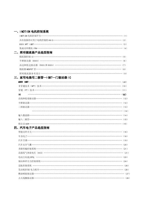
IR产品选型指南
互感器选型手册

1.1 概述............................................................................................................................................5 1.2 技术指标....................................................................................................................................5 1.3 选型说明....................................................................................................................................6 1.4 产品规格....................................................................................................................................7
1.4.9.1 AKH-L 零序电流互感器.....................................................................................47 1.4.9.2 AKH-3.3/P-φ型中压电动机保护专用电流互感器......................................49 1.4.9.3 JDG4-0.5 电压互感器.......................................................................................49 1.4.9.4 AMZK 系列电流互感器.......................................................................................50 1.5 安装方法...................................................................................................................................51 1.6 附录...........................................................................................................................................55 1.6.1 附录 1............................................................................................................................55 1.6.2 附录 2............................................................................................................................56 1.6.3 附录 3............................................................................................................................57 2. 霍尔传感器.......................................................................................................................................58 2.1 开环霍尔电流传感器..............................................................................................................58 2.2 闭环霍尔电流传感器..............................................................................................................62 2.3 直流漏电流传感器...................................................................................................................63 2.4 直流电压传感器......................................................................................................................65 3.BR 系列罗氏线圈变送器....................................................................................................................67 4.BA 系列交流电流传感器....................................................................................................................69 5.BM 系列模拟信号隔离器....................................................................................................................72 6.BD 系列电力变送器............................................................................................................................76 7. 典型案例...........................................................................................................................................82 8. 获得证书...........................................................................................................................................85
IR公司_大功率MOS管选型

I DContinuous Drain Current(A)70°Micro3Surface Mount PackagesV (BR)DSSDrain-to-Source Breakdown Voltage (V)R DS(on)On-State Resistance ()ΩI D Continuous Drain Current 25°C(A)R ΘMax.Thermal Resistance (°C/W)1FaxonDemand Number Case Outline KeyPartNumberPD Max.PowerDissipation (W)N-ChannelLogic LevelIRLML2402*912570.54200.25 1.20.95230H1IRLML2803912580.54300.251.20.93230P-ChannelLogic LevelIRLML6302*912590.54-200.6-0.62-4.8230H1IRLML5103912600.54-300.6-0.61-4.8230* Indicates low VGS(th), which can operate at VGS = 2.7VMeasured at ambient for Micro3, Micro6, Micro8, SO-8, and SOT-223 package styles. All others measured at case.1Micro3SO-8D-PakD -PakSOT-227Micro6SOT-223Micro82 Illustrations not to scaleI DContinuous Drain Current(A)70°Micro6Surface Mount PackagesV (BR)DSSDrain-to-Source Breakdown Voltage (V)R DS(on)On-State Resistance ()ΩI D Continuous Drain Current 25°C(A)R ΘMax.Thermal Resistance (°C/W)1FaxonDemand Number Case Outline KeyPartNumberPD Max.PowerDissipation (W)N-ChannelLogic LevelIRLMS1902915401.7200.10 3.2 2.675H2IRLMS1503915081.7300.103.22.675P-ChannelLogic LevelIRLMS6702*914141.7-200.20-2.3-1.975H2IRLMS5703914131.7-300.20-2.3-1.975* Indicates low VGS(th), which can operate at VGS = 2.7VMeasured at ambient for Micro3, Micro6, Micro8, SO-8, and SOT-223 package styles. All others measured at case.1Micro3SO-8D-PakD -PakSOT-227Micro6SOT-223Micro82 Illustrations not to scaleI DContinuous Drain Current(A)70°Micro8Surface Mount PackagesV (BR)DSSDrain-to-Source Breakdown Voltage (V)R DS(on)On-State Resistance ()ΩI D Continuous Drain Current 25°C(A)R ΘMax.Thermal Resistance (°C/W)1FaxonDemand Number Case Outline KeyPart NumberP D Max.PowerDissipation (W)N-Channel Logic LevelIRF7601* 912611.820 0.035 5.7 4.6 70 H3IRF7603 912621.830 0.035 5.6 4.5 70Dual N-Channel Logic LevelIRF7501* 912651.220 0.135 2.4 1.9 100 H3IRF7503 912661.2530 0.135 2.4 1.9 100P-Channel Logic LevelIRF7604* 912631.8-20 0.09 -3.6 -2.9 70 H3IRF7606 912641.8-30 0.09 -3.6 -2.9 70Dual P-Channel Logic LevelIRF7504* 912671.25-20 0.27 -1.7 -1.4 100 H3IRF7506 912681.25-30 0.27 -1.7 -1.4 100Dual N- and P-Channel Logic LevelIRF7507* 912691.2520 0.1352.4 1.9 100 H3-20 0.27 -1.7 -1.4IRF7509 912701.2530 0.135 2.4 1.9 100-30 0.27 -1.7 -1.4* Indicates low VGS(th), which can operate at VGS = 2.7VMeasured at ambient for Micro3, Micro6, Micro8, SO-8, and SOT-223 package styles. All others measured at case.1Micro3SO-8D-Pak D -PakSOT-227Micro6SOT-223Micro8 2 Illustrations not to scaleI DContinuous Drain Current(A)70°SO-8Surface Mount PackagesV (BR)DSSDrain-to-Source Breakdown Voltage (V)R DS(on)On-State Resistance ()ΩI D Continuous Drain Current 25°C(A)R ΘMax.Thermal Resistance (°C/W)1FaxonDemand Number Case Outline KeyPart Number P D Max.PowerDissipation (W)N-ChannelIRF7413913302.5300.011139.250H4IRF7413A 916132.5300.0135128.450IRF9410915622.5300.0375.850Dual N-ChannelIRF7311914352.0200.029 6.6 5.362.5H4IRF7313914802.0300.029 6.5 5.262.5IRF7333917002.0300.10 3.5 2.862.5917002.0300.050 4.9 3.962.5IRF9956915592.0300.103.52.862.5Dual P-ChannelIRF7314914352.0-200.058-5.3-4.362.5H4IRF7316915052.0-300.058-4.9-3.962.5IRF9953915602.0-300.25-2.3-1.862.5* Indicates low VGS(th), which can operate at VGS = 2.7VMeasured at ambient for Micro3, Micro6, Micro8, SO-8, and SOT-223 package styles. All others measured at case.1Micro3SO-8D-PakD -PakSOT-227Micro6SOT-223Micro82 Illustrations not to scaleI DContinuous Drain Current(A)70°SO-8Surface Mount PackagesV (BR)DSSDrain-to-Source Breakdown Voltage (V)R DS(on)On-State Resistance ()ΩI D Continuous Drain Current 25°C(A)RΘMax.ThermalResistance(°C/W)1FaxonDemand Number Case Outline KeyPart NumberP D Max.PowerDissipation (W)Dual N- and P-ChannelIRF7317 915682.020 0.029 6.6 5.3 62.5 H42.0-20 0.058 -5.3 -4.3 62.5IRF9952 915622.030 0.103.5 2.8 62.5915622.0-30 0.25 -2.3 -1.8 62.5IRF7319 916062.030 0.029 6.5 5.2 62.52.0-30 0.058 -4.9 -3.9 62.5* Indicates low VGS(th), which can operate at VGS = 2.7VMeasured at ambient for Micro3, Micro6, Micro8, SO-8, and SOT-223 package styles. All others measured at case.1Micro3SO-8D-Pak D -PakSOT-227Micro6SOT-223Micro8 2 Illustrations not to scaleI DContinuous Drain Current(A)70°SO-8Surface Mount PackagesV (BR)DSSDrain-to-Source Breakdown Voltage (V)R DS(on)On-State Resistance ()ΩI D Continuous Drain Current 25°C(A)R ΘMax.Thermal Resistance (°C/W)1FaxonDemand Number Case Outline KeyPart Number P D Max.PowerDissipation (W)N-ChannelLogic LevelIRF7401912442.5200.0228.77.050H4IRF7201911002.5300.0307.0 5.650IRF7403912452.5300.0228.55.450Dual N-ChannelLogic LevelIRF7101908712.0200.10 3.5 2.362.5H4IRF7301912382.0200.050 5.2 4.162.5IRF7303912392.0300.050 4.9 3.962.5IRF7103910952.0500.1303.02.362.5P-ChannelLogic LevelIRF7204911032.5-200.060-5.3-4.250H4IRF7404912462.5-200.040-6.7-5.450IRF7205911042.5-300.070-4.6-3.750IRF7406912472.5-300.045-5.8-3.750IRF7416913562.5-300.02-10-7.150* Indicates low VGS(th), which can operate at VGS = 2.7VMeasured at ambient for Micro3, Micro6, Micro8, SO-8, and SOT-223 package styles. All others measured at case.1Micro3SO-8D-PakD -PakSOT-227Micro6SOT-223Micro82 Illustrations not to scaleI DContinuous Drain Current(A)70°SO-8Surface Mount PackagesV (BR)DSSDrain-to-Source Breakdown Voltage (V)R DS(on)On-State Resistance ()ΩI D Continuous Drain Current 25°C(A)R ΘMax.Thermal Resistance (°C/W)1FaxonDemand Number Case Outline KeyPart Number P D Max.PowerDissipation (W)Dual P-ChannelLogic LevelIRF7104910962.0-200.250-2.3-1.862.5H4IRF7304912402.0-200.090-4.3-3.462.5IRF7306912412.0-300.10-3.6-2.962.5Dual N- and P-Channe Logic LevelIRF7307912421.4200.050 4.3 3.490H4-200.090-3.6-2.9IRF7105910972.0250.1093.5 2.862.52-250.25-2.3-1.862IRF7309912432.0300.050 4.9 3.962.5-300.10-3.6-2.9* Indicates low VGS(th), which can operate at VGS = 2.7VMeasured at ambient for Micro3, Micro6, Micro8, SO-8, and SOT-223 package styles. All others measured at case.1Micro3SO-8D-PakD -PakSOT-227Micro6SOT-223Micro82 Illustrations not to scaleI DContinuous Drain Current(A)70°SOT-223Surface Mount PackagesV (BR)DSSDrain-to-Source Breakdown Voltage (V)R DS(on)On-State Resistance ()ΩI D Continuous Drain Current 25°C(A)R ΘMax.Thermal Resistance (°C/W)1FaxonDemand Number Case Outline KeyPart Number P D Max.PowerDissipation (W)N-ChannelIRFL4105913812.1550.045 3.7 3.060H6IRFL110908612.01000.54 1.50.9660IRFL4310913682.11000.20 1.6 1.360IRFL21090868 2.02001.50.960.660IRFL214908622.02502.00.790.560P-ChannelIRFL9110908642.0-1001.2-1.1-0.6960H6N-ChannelLogic LevelIRLL3303913792.1300.031 4.6 3.760H6IRLL014N 914992.1550.14 2.0 1.660IRLL2705913802.1550.043.83.060* Indicates low VGS(th), which can operate at VGS = 2.7VMeasured at ambient for Micro3, Micro6, Micro8, SO-8, and SOT-223 package styles. All others measured at case.1Micro3SO-8D-PakD -PakSOT-227Micro6SOT-223Micro82 Illustrations not to scaleI DContinuous Drain Current(A)100°D-PakSurface Mount PackagesV (BR)DSSDrain-to-Source Breakdown Voltage (V)R DS(on)On-State Resistance ()ΩI D Continuous Drain Current 25°C(A)R ΘMax.Thermal Resistance (°C/W)1FaxonDemand Number Case Outline KeyPart Number P D Max.PowerDissipation (W)N-ChannelIRFR33039164257300.0313321 2.2H7IRFR024N9133638550.0751610 3.3IRFR41059130248550.0452516 2.7IRFR12059131869550.0273723 1.8IRFR11090524251000.54 4.3 2.75IRFR120N 91365391000.219.1 5.8 3.2IRFR391091364521000.11159.5 2.4IRFR2109052625200 1.5 2.6 1.75IRFR22090525422000.8 4.833IRFR21490703252502 2.2 1.45IRFR2249060042250 1.1 3.8 2.43IRFR3109059725400 3.6 1.7 1.15IRFR3209059842400 1.8 3.123IRFR42090599425003 2.4 1.53IRFRC2090637426004.421.33* Indicates low VGS(th), which can operate at VGS = 2.7VMeasured at ambient for Micro3, Micro6, Micro8, SO-8, and SOT-223 package styles. All others measured at case.1Micro3SO-8D-PakD -PakSOT-227Micro6SOT-223Micro82 Illustrations not to scaleI DContinuous Drain Current(A)100°D-PakSurface Mount PackagesV (BR)DSSDrain-to-Source Breakdown Voltage (V)R DS(on)On-State Resistance ()ΩI D Continuous Drain Current 25°C(A)R ΘMax.Thermal Resistance (°C/W)1FaxonDemand Number Case Outline KeyPart Number P D Max.PowerDissipation (W)P-ChannelIRFR55059161057-550.11-18-11 2.2H7IRFR53059140289-550.065-28-18 1.4IRFR90149065425-600.5-5.1-3.25IRFR90249065542-600.28-8.8-5.63IRFR91109051925-100 1.2-3.1-25IRFR91209052042-1000.6-5.6-3.63IRFR9120N 9150739-1000.48-6.5-4.1 3.2IRFR92109052125-2003-1.9-1.25IRFR92209052242-200 1.5-3.6-2.33IRFR92149165850-250 3.0-2.7-1.7 2.5IRFR93109166350-4007.0-1.8-1.12.5* Indicates low VGS(th), which can operate at VGS = 2.7VMeasured at ambient for Micro3, Micro6, Micro8, SO-8, and SOT-223 package styles. All others measured at case.1Micro3SO-8D-PakD -PakSOT-227Micro6SOT-223Micro82 Illustrations not to scaleI DContinuous Drain Current(A)100°D-PakSurface Mount PackagesV (BR)DSSDrain-to-Source Breakdown Voltage (V)R DS(on)On-State Resistance ()ΩI D Continuous Drain Current 25°C(A)R ΘMax.Thermal Resistance (°C/W)1FaxonDemand Number Case Outline KeyPart Number P D Max.PowerDissipation (W)N-ChannelLogic LevelIRLR27039133538300.0452214 3.3H7IRLR33039131657300.0313321 2.2IRLR31039133369300.0194629 1.8IRLR024N 9136338550.0651711 3.3IRLR27059131746550.042415 2.7IRLR29059133469550.0273623 1.8IRLR120N 91541391000.18511 6.9 3.2IRLR341091607521000.10159.52.4* Indicates low VGS(th), which can operate at VGS = 2.7VMeasured at ambient for Micro3, Micro6, Micro8, SO-8, and SOT-223 package styles. All others measured at case.1Micro3SO-8D-PakD -PakSOT-227Micro6SOT-223Micro82 Illustrations not to scaleI DContinuous Drain Current(A)100°D 2PakSurface Mount PackagesV (BR)DSSDrain-to-Source Breakdown Voltage (V)R DS(on)On-State Resistance ()ΩI D Continuous Drain Current 25°C(A)R ΘMax.Thermal Resistance (°C/W)1FaxonDemand Number Case Outline KeyPart NumberP D Max.PowerDissipation (W)N-ChannelIRFZ24NS 913554555 0.07 17 12 3.3 H10IRFZ34NS 913116855 0.04 29 20 2.2IRFZ44NS 9131511055 0.022 49 35 1.4IRFZ46NS 9130512055 0.020 53 37 1.3IRFZ48NS 9140814055 0.016 64 45 1.1IRF1010NS 913723.855 0.011 84 60 40IRF3205S 9130420055 0.008 110 80 0.75IRFZ44ES 9171411060 0.023 48 34 1.4IRF1010ES 9172017060 0.012 83 59 0.90IRF2807S 9151815075 0.013 71 50 1.0IRF520NS 9134047100 0.2 9.5 6.7 3.2IRF530NS 9135263100 0.11 15 11 2.4IRF540NS 91342110100 0.052 27 19 1.6IRF1310NS 91514120100 0.036 36 25 1.3IRF3710S 91310150100 0.028 46 33 1.0IRF3315S 9161794150 0.082 21 15 1.6IRF3415S 91509150150 0.042 37 26 1.0IRFBC20S 9.101450600 4.4 2.2 1.4 2.5IRFBC30S 9101574600 2.2 3.6 2.3 1.7IRFBC40S 91016130600 1.2 6.2 3.9 1.0* Indicates low VGS(th), which can operate at VGS = 2.7VMeasured at ambient for Micro3, Micro6, Micro8, SO-8, and SOT-223 package styles. All others measured at case.1Micro3SO-8D-Pak D -PakSOT-227Micro6SOT-223Micro8 2 Illustrations not to scaleI DContinuous Drain Current(A)100°D 2PakSurface Mount PackagesV (BR)DSSDrain-to-Source Breakdown Voltage (V)R DS(on)On-State Resistance ()ΩI D Continuous Drain Current 25°C(A)R ΘMax.Thermal Resistance (°C/W)1FaxonDemandNumberCase Outline KeyPart NumberP D Max.PowerDissipation (W)IRFBF20S 9166554900 8.0 1.7 1.1 2.3 H10P-ChannelIRF5305S 91386110-55 0.06 -31 -22 1.4 H10IRF4905S 914783.8-55 0.02 -74 -52 40IRF9520NS 9152247-100 0.48 -6.7 -4.8 3.2IRF9530NS 9152375-100 0.20 -14 -9.9 2.0IRF9540NS 9148394-100 0.117 -19 -13 1.6IRF5210S 91405150-100 0.06 -35 -25 1.0* Indicates low VGS(th), which can operate at VGS = 2.7VMeasured at ambient for Micro3, Micro6, Micro8, SO-8, and SOT-223 package styles. All others measured at case.1Micro3SO-8D-Pak D -PakSOT-227Micro6SOT-223Micro8 2 Illustrations not to scaleI DContinuous Drain Current(A)100°D 2PakSurface Mount PackagesV (BR)DSSDrain-to-Source Breakdown Voltage (V)R DS(on)On-State Resistance ()ΩI D Continuous Drain Current 25°C(A)R ΘMax.Thermal Resistance (°C/W)1FaxonDemand Number Case Outline KeyPart NumberP D Max.PowerDissipation (W)N-Channel Logic LevelIRL3302S 916925720 0.020 39 25 2.2 H10IRL3202S916756920 0.016 48 30 1.8IRL3102S 916918920 0.013 61 39 1.4IRL3402S 9169311020 0.01 85 54 1.1IRL3502S 9167614020 0.007 110 67 0.89IRL2703S 913604530 0.04 24 17 3.3IRL3303S 913236830 0.026 38 27 2.2IRL3103S 9133811030 0.014 64 45 1.4IRL2203NS 9136717030 0.007 116 82 0.90IRL3803S 9131920030 0.006 140 98 0.75IRLZ24NS 913584555 0.06 18 13 3.3IRLZ34NS 913086855 0.035 30 21 2.2IRLZ44NS 9134711055 0.022 47 33 1.4IRL3705NS 9150217055 0.01 89 63 0.90IRL2505S 9132620055 0.008 104 74 0.75IRLZ44S 9090615060 0.028 50 36 1.0IRL530NS 9134963100 0.1 15 11 2.4IRL2910S 91376150100 0.026 48 34 1.0* Indicates low VGS(th), which can operate at VGS = 2.7VMeasured at ambient for Micro3, Micro6, Micro8, SO-8, and SOT-223 package styles. All others measured at case.1Micro3SO-8D-Pak D -PakSOT-227Micro6SOT-223Micro8 2 Illustrations not to scaleI DContinuous Drain Current(A)100°SOT-227Surface Mount PackagesV (BR)DSSDrain-to-Source Breakdown Voltage (V)R DS(on)On-State Resistance ()ΩI D Continuous DrainCurrent 25°C(A)RΘMax.Thermal Resistance (°C/W)1FaxonDemand Number Case Outline KeyPart Number P D Max.PowerDissipation (W)N-ChannelFully Isolated Low ChargeFA38SA50LC 916155005000.1338240.25H21FA57SA50LC916506255000.0857360.20* Indicates low VGS(th), which can operate at VGS = 2.7VMeasured at ambient for Micro3, Micro6, Micro8, SO-8, and SOT-223 package styles. All others measured at case.1Micro3SO-8D-PakD -PakSOT-227Micro6SOT-223Micro82 Illustrations not to scaleI DContinuous Drain Current(A)100°I-PakThrough-Hole PackagesV (BR)DSSDrain-to-Source Breakdown Voltage (V)R DS(on)On-State Resistance ()ΩI D Continuous Drain Current 25°C(A)R ΘMax.Thermal Resistance (°C/W)1FaxonDemand Number Case Outline KeyPart Number P D Max.PowerDissipation (W)N-ChannelIRFU33039164257300.0313321 2.2H8IRFU024N 9133638550.0751610 3.3IRFU41059130248550.0452519 2.7IRFU12059131869550.0273723 1.8IRFU11090524251000.54 4.3 2.7 5.0IRFU120N 91365391000.219.1 5.8 3.2IRFU391091364521000.11159.5 2.4IRFU2109052625200 1.5 2.6 1.7 5.0IRFU22090525422000.80 4.8 3.0 3.0IRFU2149070325250 2.0 2.2 1.4 5.0IRFU2249060042250 1.1 3.8 2.4 3.0IRFU3109059725400 3.6 1.7 1.1 5.0IRFU3209059842400 1.8 3.1 2.0 3.0IRFU4209059942500 3.0 2.4 1.5 3.0IRFUC2090637426004.42.01.33.0I-PakTO-220 FullPakTO-262TO-247HEXDIPTO-220AB Illustrations not to scale** Not ratedI DContinuous Drain Current(A)100°I-PakThrough-Hole PackagesV (BR)DSSDrain-to-Source Breakdown Voltage (V)R DS(on)On-State Resistance ()ΩI D Continuous Drain Current 25°C(A)R ΘMax.Thermal Resistance (°C/W)1FaxonDemand Number Case Outline KeyPart Number P D Max.PowerDissipation (W)P-ChannelIRFU55059161057-550.11-18-11 2.2H8IRFU53059140289-550.065-28-18 1.4IRFU90149065425-600.50-5.1-3.2 5.0IRFU90249065542-600.28-8.8-5.6 3.0IRFU91109051925-100 1.2-3.1-2.0 5.0IRFU91209052042-1000.60-5.6-3.6 3.0IRFU9120N 9150739-1000.48-6.5-4.1 3.2IRFU92109052125-200 3.0-1.9-1.2 5.0IRFU92209052242-200 1.5-3.6-2.3 3.0IRFU92149165850-2503.0-2.7-1.7 2.5IRFU93109166350-4007.0-1.8-1.12.5N-ChannelLogic LevelIRLU27039133538300.0452214 3.3H8IRLU33039131657300.0313321 2.2IRLU31039133369300.0194629 1.8IRLU024N 9136338550.0651711 3.3IRLU27059131746550.04241715IRLU29059133469550.0273623 1.8IRLU120N 91541391000.18511 6.9 3.2IRLU341091607521000.10159.52.4I-PakTO-220 FullPakTO-262TO-247HEXDIPTO-220AB Illustrations not to scale** Not ratedI DContinuous Drain Current(A)100°HEXDIPThrough-Hole PackagesV (BR)DSSDrain-to-Source Breakdown Voltage (V)R DS(on)On-State Resistance ()ΩI D Continuous Drain Current 25°C(A)R ΘMax.Thermal Resistance (°C/W)1FaxonDemand Number Case Outline KeyPart Number P D Max.PowerDissipation (W)N-ChannelIRFD014907001.3600.2 1.7 1.2120H9IRFD024906991.3600.1 2.5 1.8120IRFD110903281.31000.54 1.00.71120IRFD120903851.31000.27 1.30.94120IRFD210903861.3200 1.50.60.38120IRFD220904171.32000.80.80.50120IRFD214912711.3250 2.00.570.32120IRFD224912721.3250 1.10.760.43120IRFD310912251.3400 3.60.420.23120IRFD320912261.3400 1.80.600.33120IRFD420912271.3500 3.00.460.26120IRFDC20912281.36004.40.320.21120I-PakTO-220 FullPakTO-262TO-247HEXDIPTO-220AB Illustrations not to scale** Not ratedI D Continuous Drain Current (A)100°TO-220Qg TotalGate Charge(nC)Through-Hole PackagesV (BR)DSSDrain-to-Source Breakdown Voltage (V)R DS(on)On-State Resistance ()ΩI D Continuous Drain Current 25°C (A)R ΘMax.Thermal Resistance(°C/W)1Faxon Demand Number Case OutlineKeyPart Number P D Max.Power Dissipation (W)N-ChannelLow ChargeIRF737LC91314743000.75 6.1** 1.7 3.9H11IRF740LC 910681254000.5510** 1.039IRF840LC 910691255000.858.0** 1.039IRFBC40LC910701256001.26.2**1.039I-PakTO-220 FullPakTO-262TO-247HEXDIPTO-220AB Illustrations not to scale** Not ratedI DContinuous Drain Current(A)100°TO-220ABThrough-Hole PackagesV (BR)DSSDrain-to-Source Breakdown Voltage (V)R DS(on)On-State Resistance ()ΩI D Continuous Drain Current 25°C(A)R ΘMax.Thermal Resistance (°C/W)1FaxonDemand Number Case Outline KeyPart Number P D Max.PowerDissipation (W)N-ChannelIRFZ24N 9135445550.071712 3.3H12IRFZ34N9127656550.042618 2.7IRFZ44N 9130383550.0244129 1.8IRFZ46N 9127788550.024633 1.7IRFZ48N 9140694550.0165337 1.6IRF1010N 91278130550.0127251 1.2IRF320591279150550.0089869 1.0IRFZ34E 9167268600.0422820 2.2IRFZ44E 91671110600.0234834 1.4IRF1010E 91670170600.01281570.90IRF280791517150750.0137150 1.0IRF520N 91339471000.209.5 6.79.5IRF530N 91351601000.111511 2.4IRF540N 91341941000.0522719 1.6IRF1310N 916111201000.0363625 1.3IRF3710913091501000.0284633 1.0IRF331591623941500.0822115 1.6IRF3415914771501500.0423726 1.0IRFBC209062350600 4.4 2.2 1.4 2.5IRFBC309048274600 2.2 3.6 2.3 1.7IRFBC4090506125600 1.2 6.2 3.9 1.0IRFBE2090610548006.51.81.22.3I-PakTO-220 FullPakTO-262TO-247HEXDIPTO-220AB Illustrations not to scale** Not ratedI DContinuous Drain Current(A)100°TO-220ABThrough-Hole PackagesV (BR)DSSDrain-to-Source Breakdown Voltage (V)R DS(on)On-State Resistance ()ΩI D Continuous Drain Current 25°C(A)R ΘMax.Thermal Resistance (°C/W)1FaxonDemand Number Case Outline KeyPart Number P D Max.PowerDissipation (W)IRFBE3090613125800 3.0 4.1 2.6 2.0H12IRFBF3090616125900 3.7 3.6 2.3 1.0IRFBG209060454100011 1.40.86 2.3IRFBG309062012510005.03.12.01.0P-ChannelIRF9Z24N 9148445-550.175-12-8.53.3H12IRF9Z34N 9148556-550.10-17-12 2.7IRF530591385110-550.06-31-22 1.4IRF490591280150-550.02-64-45 1.0IRF9530N 9148275-1000.20-13-9.2 2.0IRF9540N 9143794-1000.117-19-13 1.6IRF521091434150-1000.06-35-25 1.0IRF62159147983-1500.29-11-7.81.8I-PakTO-220 FullPakTO-262TO-247HEXDIPTO-220AB Illustrations not to scale** Not ratedI DContinuous Drain Current(A)100°TO-220ABThrough-Hole PackagesV (BR)DSSDrain-to-Source Breakdown Voltage (V)R DS(on)On-State Resistance ()ΩI D Continuous Drain Current 25°C(A)R ΘMax.Thermal Resistance (°C/W)1FaxonDemand Number Case Outline KeyPart NumberP D Max.PowerDissipation (W)N-Channel Logic LevelIRL3302 916965720 0.020 39 25 2.2 H12IRL3202 916956920 0.016 48 30 1.8IRL3102 916948920 0.013 61 39 1.4IRL3402 9169711020 0.01 85 54 1.1IRL3502 9169814020 0.007 110 67 0.89IRL2703 913594530 0.04 24 17 3.3IRL3303 913225630 0.026 34 24 2.7IRL3103 913378330 0.014 56 40 1.8IRL2203N 9136613030 0.007 100 71 1.230 0.007 61 43 3.2IRL3803 9130115030 0.006 120 83 1.0IRLZ24N 913574555 0.06 18 13 3.3IRLZ34N 913075655 0.035 27 19 2.7IRLZ44N 913468355 0.022 41 29 1.8IRL3705N 9137013055 0.01 77 54 1.2IRL2505 9132520055 0.008 104 74 0.75IRL520N 9149447100 0.18 10 7.1 3.2IRL530N 9134863100 0.10 15 11 2.4IRL540N 9149594100 0.044 30 21 1.6IRL2910 91375150100 0.026 48 34 1.0I-PakTO-220 FullPakTO-262TO-247HEXDIPTO-220AB Illustrations not to scale** Not ratedI D Continuous Drain Current (A)100°TO-220 FullPak (Fully Isolated)Qg TotalGate Charge(nC)Through-Hole PackagesV (BR)DSSDrain-to-Source Breakdown Voltage (V)R DS(on)On-State Resistance ()ΩI D Continuous DrainCurrent 25°C(A)R ΘMax.Thermal Resistance (°C/W)1Fax on Demand Number Case OutlineKeyPart Number P D Max.Power Dissipation (W)N-ChannelLow ChargeIRFI740GLC91209404000.55 6.0** 3.139H13IRFI840GLC 91208405000.85 4.8** 3.139IRFIBC40GLC91211406001.24.0**3.139I-PakTO-220 FullPakTO-262TO-247HEXDIPTO-220AB Illustrations not to scale** Not ratedI DContinuous Drain Current(A)100°TO-220 FullPak (Fully Isolated)Through-Hole PackagesV (BR)DSSDrain-to-Source Breakdown Voltage (V)R DS(on)On-State Resistance ()ΩI D Continuous Drain Current 25°C(A)R ΘMax.Thermal Resistance (°C/W)1FaxonDemand Number Case Outline KeyPart Number P D Max.PowerDissipation (W)N-ChannelIRFIZ24N 9150126550.07139.2 5.8H14IRFIZ34N9148931550.041913 4.8IRFIZ44N 9140338550.02428200.024IRFIZ46N 9130640550.023122 3.8IRFIZ48N 9140742550.0163625 3.6IRFI1010N 9137347550.0124431 3.2IRFI32059137448550.0085640 3.1IRFIZ24E 9167329600.071149.6 5.2IRFIZ34E 9167437600.0422115 4.1IRFI510G 90829271000.54 4.5 3.2 5.5IRFI520N 91362271000.207.2 5.1 5.5IRFI530N 91353331000.11117.8 4.5IRFI540N 91361421000.0521813 3.6IRFI1310N 91611451000.0362216 3.3IRFI371091387481000.0252820 3.1IRFI620G 90832302000.8 4.1 2.6 4.1IRFI630G 90652322000.4 5.9 3.7 3.6IRFI640G 90649402000.189.8 6.2 3.1IRFI614G 9083123250 2.0 2.1 1.3 5.5IRFI624G 9083330250 1.1 3.4 2.2 4.1IRFI634G 90738322500.45 5.6 3.5 3.6IRFI644G 90739402500.287.953.1I-PakTO-220 FullPakTO-262TO-247HEXDIPTO-220AB Illustrations not to scale** Not ratedI DContinuous Drain Current(A)100°TO-220 FullPak (Fully Isolated)Through-Hole PackagesV (BR)DSSDrain-to-Source Breakdown Voltage (V)R DS(on)On-State Resistance ()ΩI D Continuous Drain Current 25°C(A)R ΘMax.Thermal Resistance (°C/W)1FaxonDemand Number Case Outline KeyPart Number P D Max.PowerDissipation (W)IRFI720G 9083430400 1.8 2.6 1.7 4.1H14IRFI730G 9065032400 1.0 3.7 2.3 3.6IRFI740G 90651404000.55 5.4 3.4 3.1IRFI734G 9100135450 1.2 3.4 2.1 3.6IRFI744G 91002404500.63 4.9 3.1 3.1IRFI820G 9064130500 3.0 2.1 1.3 4.1IRFI830G 9064632500 1.5 3.12 3.6IRFI840G 90642405000.85 4.6 2.9 3.1IRFIBC20G 90850306004.41.71.1 4.1IRFIBC30G 90851356002.2 2.5 1.63.6IRFIBC40G 9085240600 1.2 3.5 2.2 3.1IRFIBE20G 9085330800 6.5 1.4.86 4.1IRFIBE30G 9085435800 3.0 2.1 1.4 3.6IRFIBF20G 90855309008.0 1.2.79 4.1IRFIBF30G90856359003.71.91.23.6P-ChannelIRFI9Z24N 9152929-550.175-9.5-6.7 5.2H14IRFI9Z34N 9153037-550.10-14-10 4.1IRFI49059152663-550.02-41-29 2.4IRFI9540G 9083742-1000.117-13-9.2 3.6IRFI9540N 9148742-1000.117-13-9.2 3.6IRFI52109140448-1000.06-20-14 3.1IRFI9634G 9148835-2501.0-4.1-2.63.6I-PakTO-220 FullPakTO-262TO-247HEXDIPTO-220AB Illustrations not to scale** Not ratedI DContinuous Drain Current(A)100°TO-220 FullPak (Fully Isolated)Through-Hole PackagesV (BR)DSSDrain-to-Source Breakdown Voltage (V)R DS(on)On-State Resistance ()ΩI D Continuous Drain Current 25°C(A)R ΘMax.Thermal Resistance (°C/W)1FaxonDemand Number Case Outline KeyPart Number P D Max.PowerDissipation (W)N-ChannelLogic LevelIRLI2203N 9137847300.0076143 3.2H14IRLI38039132048300.0066747 3.1IRLIZ24N 9134426550.06149.9 5.8IRLIZ34N 9132931550.0352014 4.8IRLIZ44N 9149838550.0222820 4.0IRLI3705N 9136947550.014733 3.2IRLI25059132763550.00858412.4IRLI520N 91496271000.187.7 5.4 5.5IRLI530N 91350331000.10117.8 4.5IRLI540N 91497421000.04420143.6IRLI291091384481000.02627193.1P-ChannelLogic LevelIRFI9520G 9083537-1000.6-5.2-3.6 4.1H14IRFI9530G 9083638-1000.03-7.7-5.4 3.6IRFI9620G 9087430-200 1.5-3.0-1.9 4.1IRFI9630G 9083840-2000.8-4.3-2.7 3.6IRFI9640G9083940-2000.5-6.1-3.93.1I-PakTO-220 FullPakTO-262TO-247HEXDIPTO-220AB Illustrations not to scale** Not ratedI D Continuous Drain Current (A)100°TO-247Qg TotalGate Charge(nC)Through-Hole PackagesV (BR)DSSDrain-to-Source Breakdown Voltage (V)R DS(on)On-State Resistance ()ΩI D Continuous Drain Current 25°C (A)R ΘMax.Thermal Resistance (°C/W)1Fax on Demand Number Case OutlineKeyPart Number P D Max.Power Dissipation (W)1N-ChannelLow ChargeIRFP350LC912291904000.3018**0.6570H16IRFP360LC 912302804000.2023**0.4598IRFP450LC 912311905000.4016**0.6570IRFP460LC 912322805000.2720**0.4598IRFPC50LC 912331906000.6013**0.6570IRFPC60LC912342806000.4016**0.4598I-PakTO-220 FullPakTO-262TO-247HEXDIPTO-220AB Illustrations not to scale** Not rated。
IR器件选型

IR产品选型指南
28L PDIP 44L PLCC 28L SOIC
28L PDIP 44L PLCC 28L SOIC
28L PDIP 44L PLCC 28L SOIC
2005 福建贝能科技有限公司
Vs
输出源/吸收电流
Vcc 范围
+200/-420m A
600V
8L PDIP 8L SOIC 8L PDIP 8L SOIC
600V
+130/-270m A
10-25V(低压关断)
IR2106 IR2106S IR21064 IR21064S
8L PDIP 8L SOIC 14L PDIP 14L SOIC
600V
+120/-250m A
10-25V(低压关断)
10-25V(低压关断) 10-25V(低压关断) 10-25V(低压关断) 10-25V(低压关断) 10-25V(低压关断) 10-25V(低压关断)
13
贝能科技 IR 产品选型指南
传输匹配 最大 15ns 最大 50ns 最大 50ns 最大 30ns 最大 50ns 最大 10ns
特
性
操作频率可达 1MHz
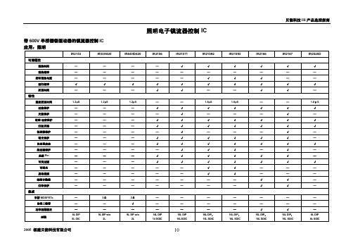
带 600V 半桥栅极驱动器的镇流器控制 IC 应用:照明
可编程性 预热时间 预热频率
闭环预热电流 运行频率 死区时间
特性 固定死区时间 过流保护 欠流保护 故障-击穿保护 灯丝开路 低谐振保护 暗光保护 自动重启动 热过载保护 关断 Pin 可调过流 可调光 启动检测 故障计数器 灯寿保护
集成 半桥 MOSFETs 自举二极管 功率因数校正
IR2112 IR2112-1 IR2112-2 IR2112S
IR选型指南
600V 应用系统,输出推/拉电流为 200/420mA
型号
电路
VCC 范围
IR2130 3-Phase Bridge Driver IR2131 3HI/3LO MOS Driver IR2132 3-Phase Bridge Driver 10-25V with UVLO IR2133 3-Phase Bridge Driver IR2135 3-Phase Bridge Driver
Ton/Toff
VIH/VIL
Vitrip+ UVCC/BS+/CCBS-
IR2136
IR21362
12-25V with UVLO
IR21363
IR21365
IR21366 IR21367
12-20V with UVLO
IR21368
10V/20V
___ __ 400ns/380ns 2.7V/1.7V 0.46V
电路
IC@25°C IC@100°C VCE(on)@25°C
Co-Pack 12A
6.8A
2.1V
Co-Pack 12A
6.8A
2.1V
Co-Pack 13A
7A
1.8V
Co-Pack 17A
9A
1.8V
Co-Pack 22A
12A
1.8V
Co-Pack 31A
15A
1.8V
Isolated TO-220 Full-Pak
Co-Pack 9A
6A
1.8V
Isolated TO-220 Full-Pak
Co-Pack 12A
Hale Waihona Puke 8A1.8VIsolated TO-220 Full-Pak
艾索莱特产品选择指南说明书

THE GOOD, BETTER, BEST LIST Isolite’s Product Selection Guide*Click the Product You Wish to View on EXITS & COMBOSRLReliance Series ThermoplasticLED Exit SignCMBThermoplastic LED Exit Sign &Emergency ComboRLC-LEDThermoplastic Exit & EmergencyComboNo Remote Capacity Remote Capacity, Lamps Removable Remote Capacity, Lamps Removable Thermoplastic Thermoplastic ThermoplasticFrom 32°F to 122°F From 32°F to 104°F From 50°F to 104°F• UL 924• CEC Title 20 Compliant• UL 924• UL Listed for Damp Location• UL 924• UL Listed for Damp LocationEDCEconomical Die-Cast LED Exit SignLPDCDie-Cast Aluminum LED Exit SignTL2.0Thin Line Die-Cast LED Exit Sign CEC Die-Cast Aluminum Die-Cast Aluminum Die-Cast AluminumFrom 32°F to 122°F From 32°F to 102°F From 50°F to 104°F• UL 924• UL Listed for Damp Location• UL 924• UL Listed for Damp Location• UL 924• CEC Title 20 CompliantEUGUniversal Surface MountEdge-Lit LED Exit SignUELUniversal Recessed Edge-Lit LEDExit SignELT2Edge-Lit LED Exit SignExtruded Aluminum & Acrylic Lens Extruded Aluminum with Steel RecessedBackbox & Acrylic LensPrecision die-cast aluminum housing witha flawless, laser-formed acrylic legendFrom 50°F to 104°F From 50°F to 104°F From 32°F to 102°F• UL924• UL Listed for Damp Location• UL924• UL Listed for Damp Location• UL 924• CEC Title 20 CompliantRWLWet Location ThermoplasticLED Exit SignMAXWet Location Die-Cast LED Exit SignHLXNEMA 4X LED Exit SignUV Stabilized Polycarbonate Housing withStainless Steel Captive Screws to SecureLens Cover to HousingHeavy-Duty 0.420” Cast Aluminum withImpact Resistant Polycarbonate ShieldCorrosion Resistant ABS ThermoplasticHousing & Fully Gasketed with Hot BondedSiliconeFrom -4°F to 122°F• EM: 32ºF – 113ºF• EM (With H1/H2): -4ºF – 113ºF• AC: -20ºF – 113ºF• Without Internal Heater: From 50°F to 104°F• With Internal Heater: From -4°F to 104°FTHE GOOD, BETTER, BEST LIST Isolite’s Product Selection Guide*Click the Product You Wish to View on EXITS & COMBOSCONTINUEDRWL-CWet Location Thermoplastic LEDExit SignMAX-CWet Location Die-Cast Exit &Emergency ComboHLX-CNEMA 4X Exit & Emergency ComboUV Resistant Polycarbonate Faceplate withHigh Impact Corrosion ResistantThermoplasticHeavy-Duty 0.420” Cast Aluminum LampHousing Constructed of VandalResistant PolycarbonateCorrosion Resistant, ABS Thermoplastic,Fully Gasketed with Hot Bonded SiliconeFrom 32°F to 122°F From 50°F to 104°F• Without Internal Heater: From 50°F to 104°F• With Internal Heater: From -4°F to 104°F• UL 924PHLThermoplastic PhotoluminescentExit SignPHAluminum Frame PhotoluminescentExit SignPH100Photoluminescent Exit SignThermoplastic Frame with Strontium OxideAluminate Photoluminescent PigmentMolded Into a Rigid Fire/Flame-ResistantPVC SheetExtruded Aluminum Frame With StrontiumOxide Aluminate Photoluminescent PigmentMolded Into a Rigid Flame/Fire-Resistant PVCSheetDurable ABS Background Panel Available inRed, Green, or Black, with PhotoluminescentLettersNon-Electrical Non-Electrical Non-ElectricalSLX-60ABS Plastic Frame Self-LuminousExit Sign2040-01Aluminum Frame Self-LuminousExit Sign880Thinline Aluminum Self-LuminousExit SignFlame Retardant, UV Stabilized, InjectionMolded ABS FrameExtruded Aluminum Frame with PaintedExtruded Aluminum StencilExtruded Aluminum Frame with PaintedExtruded Aluminum StencilFrom -67°F to 176°F From -67°F to 176°F From -67°F to 176°F• UL Listed to standard UL924 & CAN/• ULC-S572• UL Listed to standard UL924 & CAN/• ULC-S572• UL Listed to standard UL924 & CAN/• ULC-S572SLX-60 (VR)ABS Plastic Frame Self-LuminousExit Sign2040-95Vandal Resistant Self-LuminousExit Sign2040-70Vandal Proof Institutional Self-Luminous Exit SignFlame Retardant, UV Stabilized, InjectionMolded ABS Frame with VR ShieldExtruded Aluminum Frame Mounted inMolded ABS Protective Enclosure withPainted Aluminum StencilCast Aluminum Frame, 0.187” Thick,Extends from Faceplate At 45° Angle fromthe WallFrom -67°F to 176°F From -67°F to 176°F From -67°F to 176°F• UL Listed to standard UL924 & CAN/• UL Listed to standard UL924 & CAN/• UL Listed to standard UL924 & CAN/THE GOOD, BETTER, BEST LIST Isolite’s Product Selection Guide*Click the Product You Wish to View on EXITS & COMBOSCONTINUEDCLPChicago Approved LED Exit SignPGChicago Approved LED Edge-LitExit SignDurable 20-Gauge Steel Precision, Die-Cast Aluminum Housing withLaser Formed Acrylic LegendFrom 32°F to 122°F From 50°F to 104°F• City of Chicago Approved• CEC Title 20 Compliant• City of Chicago Approved• UL 924EDC-NYCNYC Approved EconomicalDie-Cast LED Exit SignELT2 with R8Edge-Lit LED Exit SignPremium-Grade, Aluminum Housing Precision Die-Cast Aluminum Housing with aFlawless, Laser-Formed Acrylic LegendFrom 32°F to 122°F From 32°F to 102°F• New York City Approved• UL Listed for Damp Location• UL 924• CEC Title 20 CompliantLP-CTMASteel Connecticut & MassachusettsCompliant LED Mobility Exit SignLPX-CTMAConnecticut & MassachusettsAluminum LED Mobility Exit SignECTMAConnecticut & MassachusettsCompliant Recessed Mobility Exit Sign Durable 20-Gauge Steel Durable, Extruded Aluminum Durable 20-Gauge Steel with White-BakedPowder Coat Finish & High Clarity AcrylicFrom 50°F to 113°F From 50°F to 113°F From 50°F to 113°F• CSA-US listed• Meets or exceeds UL 924 standards• CSA-US listed• UL 924• CSA-US listed• Meets or Exceeds UL 924 StandardsEU-CTMAConnecticut & MassachusettsCompliant Indoor Mobility Exit SignDurable 20-Gauge Steel with White-BakedPowder Coat Finish & High Clarity AcrylicFrom 50°F to 113°F• CSA-US listed• Meets or Exceeds UL 924 StandardsTHE GOOD, BETTER, BEST LIST Isolite’s Product Selection Guide*Click the Product You Wish to View on EXITS & COMBOSCONTINUEDHZEClass 1 Div 2 LED Exit SignHZCClass 1 Div 2 Exit & EmergencyComboEXPExplosion Proof Edge-Lit LEDExit SignDurable, Corrosion Resistant, GrayFiberglass & Fully Gasketed for Harsh &Hazardous Locations. High Clarity, ScratchResistant, Clear Polycarbonate FaceFully Gasketed, Die-Cast AluminumHousing with Impact ResistantPolycarbonate Lens Stainless Steel MountingFeet & Hardware Industrial Gray ColorStandardPrecision Die-Cast Aluminum Housing WithA Flawless, Laser-Formed Acrylic LegendFrom 50°F to 104°F From 50°F to 104°F From 50°F to 104°FLPDCCGDie-Cast Aluminum CustomGraphics SignTLCG2Thin Line Die-Cast Custom GraphicsLED Exit SignHeavy-Duty, Two Piece, Die-Cast AluminumAlloy Walls & Removable, Front Stencil Facewith Overlapping Light SealHeavy Duty, Two Piece Walls Constructed fromDie Cast Aluminum Alloy & Removable FrontStencil Face with Overlapping Light SealFrom 32°F to 102°F From 50°F to 104°F• UL 924• UL 924RL2LEDReliance Series Compact LEDEmergency LightEL16MR16 Emergency LightBUGHigh Performance LED EmergencyLightUV Stabilized, UL94V-O Flame Retardant,ABS Injection-Molded Thermoplastic5VA Flame Resistant, High-Impact Resistant,Thermoplastic in White or Black Finish5VA Flame Rated, Injection Molded AbsThermoplastic HousingFrom 50°F to 104°F From 68°F to 104°F From 50°F to 104°F125 Lumens per Lamp Lamp Option Dependent300-650 Lumens per LampTHE GOOD, BETTER, BEST LIST Isolite’s Product Selection Guide*Click the Product You Wish to View on EMERGENCY LIGHTINGCONTINUEDGNSDGenie MR16 Fully RecessedEmergency LightLMIGN2LED Compact Fully RecessedEmergency LightMIGN22nd Mini-Genie Fully RecessedCompact LED Emergency LightTextured White Powder, Coated Die-CastZinc Frame & DoorTextured, White Powder Coated, Die-CastZinc Frame & DoorTextured, White Powder Coated, Die-CastZinc Frame & DoorLamp Option Dependent561 Lumens407 Lumens per Lamp• LC: From 45°F to 85°F• NC: From 32°F to 102°FFrom 32°F to 102°F From 10°C to 40°CELS27-140 Watt Emergency LightELH120-360 Watt Emergency LightInjection Molded ABS Housing20-Gauge Steel Cabinet with Durable WhitePowder-Coat Finish20-Gauge Steel Cabinet with Durable WhitePowder-Coat Finish20-20-2With Internal Heater: 16°F to 104°F From 50°F to 113°F From 50°F to 113°FELL12-60 Watt Emergency Light20-Gauge Steel Cabinet with Durable WhitePowder-Coat Finish0-2From 50°F to 113°FTHE GOOD, BETTER, BEST LIST Isolite’s Product Selection Guide*Click the Product You Wish to View on EMERGENCY LIGHTINGCONTINUEDELEDArchitectural Outdoor LED LightOWLOutdoor Wet Location EmergencyLightDie-Cast Housing with Polycarbonate Lens &Mirror ReflectorQuality Pressure Die-Cast Aluminum HousingFinished in Durable Polyester Powder Coat1050 Lumens / 4000K CCT• AC Mode: 1530 Lumens• EM Mode: 600 Lumens• 3000K CCTHZLHazardous Location EmergencyLightFully Gasketed NEMA 4X Rated Fiberglass withHousing Durable Gray Powder-Coat FinishFully Gasketed, Die-Cast Aluminum HousingWith Impact Resistant Polycarbonate Lens0-20-2• Without Internal Heater: From 50°F to 104°F• With Internal Heater: From -4°F to 104°FFrom 50°F to 104°FRL2LED with LWReliance Series Compact LEDEmergency LightHZNNEMA 4X/IP66 Emergency LightHZZHazardous Location EmergencyLightUv Stabilized, UL94V-O Flame Retardant,ABS Injection-Molded ThermoplasticFully Gasketed, Die-Cast Aluminum Housingwith Impact Resistant Polycarbonate LensFully Gasketed, Die-Cast Aluminum Housingwith Impact Resistant Polycarbonate Lens125 Lumens per Lamp Lamp Option Dependent Lamp Option DependentFrom 50°F to 104°F• Without Internal Heater: From 50°F to 104°F• With Internal Heater: From -4°F to 104°FFrom 50°F to 104°F。
光耦选型经典指南

光耦选型经典指南1.0.目的:针对光偶选型,替代,采购,检测及实际使用过程中出现的光偶特性变化引起的产品失效问题,提供指导。
2.0.适用范围:本指导书适用于瑞谷光偶的设计,选型,替代等。
3.0.说明:目前发现,因光偶的选型,光偶替代,光偶工作电流,工作温度设计不当等原因导致产品出现问题,如何减少选型,设计,替代导致的产品问题,这里将制订出相关指导性规范。
4.0.内部结构图及CTR 的计算方法:●规格定义CTR:Ice/I F*100% (检测条件:I F =5 ma Vce=5V, 2701,2801系列)5.0.光偶主要特性分析,设计选型替代要求:5.1外观尺寸:设计,选型,替代注意:●封装正确,本体MARK字迹要清晰,品牌正确,与技术规格书一致;●替代时,如都为标准件封装,基本上装配没有问题,但需注意厚度是否与原料相同,是否满足整机的工艺要求。
5.2不同输入控制电流I F,CTR 值不同;●由图表显示,IF在5-15ma时CTR值最大;在小于5mA时(目前我们产品设计大多如此),CTR值一般小于正常额定规格值;●附加Cosmo KPS2801-B 实测数据:J16(2009年第16周生产)的光耦在室温下的CTRI F(VCE=5V)#1 #2 #3 #4 #5 #6 #71mA 88.3% 90.48% 90.57% 86.56% 87.1% 85.12% 87..39%2mA 133% 130% 130% 125% 135% 122% 126%3mA 150% 154% 154% 147% 151% 139% 150%5mA 177% 187% 183% 177% 178% 170% 177%J25(2009年第25周生产)的光耦在室温下的CTRI F(VCE=5V)#1 #2 #3 #4 #5 #6 #71mA 69.24% 78.61% 66.68% 66.41% 65.7% 75.5% 79.0%2mA 97% 105% 110% 104% 101% 122% 126%3mA 121% 121% 131% 132% 129% 151% 151%5mA 166% 147% 174% 174% 173% 210% 196%●评注:IF不同,CTR不同,且差异非常大;不同DATECODE的也有差异,但在IF=5ma时,CTR值都在规格(130-260)范围内;●设计,选型,替代注意:设计时工作电流应接近来料的检测电流值(目前大多IF=5ma),否则应用的CTR值无法保证,产品动态性能将很差;5.3不同环境温度,CTR 值不同;●由图表显示,CTR 值与光偶的工作环境有关,温度太高或太低都小于常温附近的检测值;●附加Cosmo KPS2801-B 实测数据(单体):光耦随温度变化的CTR(%)#1 #2 #3 #4-40℃149 147 137 13025℃170 172 176 16785℃140 143 149 141注:测试条件:V CE=5V,I F为5mA●评注:温度不同,CTR不同,温度太高或太低都低于常温,且差异很大;●设计,选型,替代注意:产品在高低温CTR的值是否满足产品反馈环路的增益?产品动态稳定吗?开关机,输出是否产生震荡掉沟等不良,5.4光偶有RL阻值大小及工作频带带宽要求;●由图表可看出:光偶有频带要求,如上图为KPS-2801光偶,工作频率基本在500KHZ以内,且对于高频工作时,RL(输出分压电阻)要小;●设计,选型,替代注意:产品工作频率,RL选取阻值务必在带宽内,且考虑IF电流大小,VCE工作压降;5.5不同环境温度,输入控制电流可能产生变化:●由图表可看出:环境温度超过55-60度后,输入控制电流I F 的最大值将随着温度上升而显著减小;●设计,选型,替代注意:选取合适的IF电流,使输入控制电流的变动都能及时反馈到输出端,保证产品反馈环的稳定;5.6 环境温度及功耗特性曲线●由图表可看出:光偶的输出部分(或集电极)功耗在低温时,在温度高时数值变小;●设计,选型,替代注意:1,器件常温时可提供功耗值;2,高温过程变化曲线;3,有必要计算产品在高温工作时光偶功耗值;4,替代时考虑常温功耗,高温状态替代料是否优于原料;5.7 Ic,If,Vce关系曲线:●由图表可看出:Vce必须大于一定电压,Ic才能达到最大,CTR值才会大;●设计,选型,替代注意:Vce在电路应用中,保证设计有一定的电压值,否则Ic将较小,CTR将较小,一般设计Vc应大于3V。
光耦选型最全指南及各种参数说明

光耦选型手册光耦简介:光耦合器(opticalcoupler,英文缩写为OC)亦称光电隔离器或光电耦合器,简称光耦。
它是以光为媒介来传输电信号的器件,通常把发光器(红外线发光二极管LED)与受光器(光敏半导体管)封装在同一管壳内。
当输入端加电信号时发光器发出光线,受光器接受光线之后就产生光电流,从输出端流出,从而实现了“电—光—电”转换。
光耦合器一般由三部分组成:光的发射、光的接收及信号放大。
输入的电信号驱动发光二极管(LED),使之发出一定波长的光,被光探测器接收而产生光电流,再经过进一步放大后输出。
这就完成了电—光—电的转换,从而起到输入、输出、隔离的作用。
光耦的分类:(1)光电耦合器分为两种:一种为非线性光耦,另一种为线性光耦。
非线性光耦的电流传输特性曲线是非线性的,这类光耦适合于开关信号的传输,不适合于传输模拟量。
常用的4N系列光耦属于非线性光耦。
线性光耦的电流传输特性曲线接近直线,并且小信号时性能较好,能以线性特性进行隔离控制。
常用的线性光耦是PC817A—C系列。
(2)常用的分类还有:按速度分,可分为低速光电耦合器(光敏三极管、光电池等输出型)和高速光电耦合器(光敏二极管带信号处理电路或者光敏集成电路输出型)。
按通道分,可分为单通道,双通道和多通道光电耦合器。
按隔离特性分,可分为普通隔离光电耦合器(一般光学胶灌封低于5000V,空封低于2000V)和高压隔离光电耦合器(可分为10kV,20kV,30kV等)。
按输出形式分,可分为:a、光敏器件输出型,其中包括光敏二极管输出型,光敏三极管输出型,光电池输出型,光可控硅输出型等。
b、NPN三极管输出型,其中包括交流输入型,直流输入型,互补输出型等。
c、达林顿三极管输出型,其中包括交流输入型,直流输入型。
d、逻辑门电路输出型,其中包括门电路输出型,施密特触发输出型,三态门电路输出型等。
e、低导通输出型(输出低电平毫伏数量级)。
f、光开关输出型(导通电阻小于10Ω)。
瑞能半导体科技股份有限公司产品选择指南说明书

PRODUCT SELECTION GUIDEWeEn SemiconductorsEV CHARGERTELECOM POWERSOLAR INVERTERHOME APPLIANCEMOTOR CONTROL瑞能半导体科技股份有限公司,源自恩智浦半导体标准产品事业部,注册于2015年8月5号,运营中心落户上海,全资子公司和分支机构包括吉林芯片生产基地、上海和英国产品及研发中心、香港物流中心以及遍布全球其他国家的销售和客户服务点。
作为全球功率半导体行业的佼佼者,瑞能始终专注于研发行业领先、广泛且深入的双极功率半导体产品组合,包括:碳化硅二极管,可控硅整流器和三端双向可控硅、功率二极管、高压晶体管等。
产品广泛应用于电信、计算机、消费类电子产品、智能家电、照明、汽车和电源管理应用等市场领域。
自诞生以来,瑞能已走过逾 50 年辉煌历程,作为全球功率半导体行业的佼佼者, 我们的目标是帮助客户提高成本效益和生产效率,促进中国及全球智能制造行业的发展。
19691980s2000s20062020201520132009High Voltage Transistors (HVT)Fast, Ultrafast & Hyperfast Power DiodesBipolar 4-Quadrant TriacsBipolar 3-Quadrant Hi-Com TriacsHyperfast diodes Triac & SCR Planar Technology PlatformACT & ACTT Platform (AC Switch), Casco DiodesTemperature & Overload Protected Triac (TOPTriac)Automotive SiC Standard Power Diodes Automotive SCRs 1600V Planar SCRsSilicon Carbide DiodesEnhanced E ciency Pt Planar diodes (EEPP)Generation 2: Schottky Barrier Diodes High Voltage SCRsSuper Advanced Best E ciency Rectifier Diodes (SABER)Generation 1: Schottky Barrier DiodesWeEn Semiconductors:Span o from NXP, Over 50-Y ears Leading Experience in PowerWeEn Semiconductors Co., Ltd, span o from NXP, registered on Aug 5, 2015 .The operational headquarters locates in Shanghai and the company’s wholly-owned subsidiaries and branches include: the front-end fabrication in Jilin, north east China, the warehouse and distribution center in Hong Kong and research & development centers in Shanghai and Manchester, UK. WeEn also has sales o ces set up and customer service access throughout the world. As a key player in the semiconductor industry, WeEn has focused on developing a large portfolio of industry-leading bipolar power products including thyristors (i.e. silicon controlled rectifiers and triacs), silicon power diodes and high voltage transistors. Addition-ally, WeEn has developed a state-of-the-art portfolio of silicon carbide diodes and power Schottky diodes as well as making available a number of AECQ products. All these products are widely used in the markets for telecommunications, computers, consumer electronics, intelligent home appliances, lighting, automotive and power management applications.With over 50 years of design and manufacture experience, WeEn helps to drive up e ciency in your designs and to contribute to the development of China and global intelligent manufacturing.aim is to help our customers achieve higher cost e ciency and production e ciency and to contribute to the development of China and global intelligent manufacturing.AC Thyristor Triacs / AC ThyristorsAC Thyristor TriacsAC ThyristorsTemperature and Overload Protected Triacs (Toptriac)3Q Hi-com Triacs (0.8A - 45A)4Q Triacs (0.6A - 45A)Silicon Controlled Rectifiers (0.8A - 126A)Power DiodesHyperfast Power Diodes1200V Planar Hyperfast Power DiodesPower DiodesUltrafast Power DiodesSiC Schottky DiodePower Schottky Diodes600V - 1600V Standard Power DiodesPower Diode BridgePower Diode ModuleWeEn High Voltage 1600V SCRs1600V/50A & 1600V/80A, Planar PassivatedWeEn 30A Hi-Com TM TriacsDFN 8x8 PackageWeEn Silicon Carbide Junction Barrier Schottky (JBS) 650V and 1200V SeriesWeEn Products for EV On Board ChargerWeEn Products in Smart HomeCertificationsWeEn Nanchang Reliability & Failure Analysis Laboratory 040506070809101112131415161718193CONTENTS(3Q Hi-Com power switches, overvoltage protection)AC Thyristor Triacs / AC ThyristorsAC Thyristor TriacsTemperature and Overload Protected Triacs (Toptriac)2Q Hi-Com power switches, exclusive negative gate triggering, over-temperature protectionAC Thyristor Triacs part numbering AC Thyristors part numbering(2Q Hi-Com power switches, exclusive negative gate triggering, ’Common’ mounting base, overvoltage protection)AC ThyristorsI GT key: C = 35 mA; C0 = 5 - 30 mA; E = 10 mAT : high T j (max) 150 °C N: Enhanced Dynamic PerformanceI GT key: D = 5 mA; E = 10 mAI GT key:C0 = 5 - 35mATypes in bold red italic represent products in development4Types in bold red represent new productsHi-Com Triacs (0.8A - 45A)3Q5I key:* High I TSM **: Enhanced immunity to false triggering T: high T j (max) 150CD = 5mA (10mA in 3+);E = 10mA (25mA in 3+);F = 25mA (70mA in 3+); - = 35mA (70mA in 3+);G = 50mA (100mA in 3+); G0 = 50mA (100mA in 3+), 10mA min4Q Triacs(0.6A - 45A)4Q Triacs part numbering6Silicon Controlled Rectifiers(0.8A - 126A)Silicon Controlled Rectifiers part numberinghigh I TSM ** Hi-Com / fast turn-off T: high T j (max) 150 A: Automotive quali ed AEC-Q101°CTypes in bold red represent new productsTypes in bold red italic represent products in development7Hyperfast Power Diodes1200V Planar Hyperfast Power DiodesTypes in bold red represent new productsTypes in bold red italic represent products in development8Types in bold red italic represent products in development9SOD113(2-pin SOT186A)SOT429(3-pin TO247)NXPSC04650X NXPSC06650X SiC Schottky Diode650V SiC Schottky Diode• Highly stable switching performance • High forward surge capability IFSM • Extremely fast reverse recovery time• Superior in ef ciency to Silicon Diode alternatives • Reduced losses in associated MOSFET • Reduced EMI• Reduced cooling requirements • RoHS compliantI n t h e S p o t l i g h t Types in bold red italic represent products in development1200V SiC Schottky Diode• Highly stable switching performance • High forward surge capability IFSM • Extremely fast reverse recovery time• Superior in ef ciency to Silicon Diode alternatives • Reduced losses in associated MOSFET • Reduced EMI• Reduced cooling requirements • RoHS compliant• High junction operating temperature capability (T j(max) = 175 °C)I n t h e S p o t l i g h t10Power Schottky Diodes600V - 1600V Standard Power DiodesPower Diode Moduleemploying series die technology for the lowest possible trrWDMF75M16• Three phase recti ers• Heat transfer through aluminium oxide DBC, ceramic isolated metal baseplate • High voltage capability• High inrush current capability • Planar process• High operating temperature capability (T j (max) = 150°C)I n t h e S p o t l i g h tPower Diode BridgeTypes in bold red represent new productsWDMF75M1611WeEn High Voltage 1600V SCRs1600V/50A & 1600V/80A, Planar PassivatedProductTYN50W-1600T TYN80W-1600T TO-247TO-247Key ParametersPackageParametersPackageIT(AV)IT(RMS)VDRMIGTITSMTj(max)dIT/dtdVD/dtTO-24750A79A1600V80mA max650A @ 10ms150°C150A/us1500V/µs @150o CTYN50W-1600TTO-24780A126A1600V80mA max850A @ 10ms150°C150A/us1000V/µs @150o CTYN80W-1600TProduct 12WeEn 30A Hi-Com TM TriacsProductApplications PackageParametersI T(RMS)V DRM I GT I TSM T j(max)dI T /dt30A 800V 50mA max 270A @ 20ms 150°C 100A/µsBTA330 BT series30A 800V 35mA max 270A @ 20ms 150°C 100A/µsBTA330 CT seriesBTA330-800BT BTA330X-800BT BTA330Y-800BT BTA330Y-800CT BTA330B-800BT BTA330B-800CTTO220TO220FP IITO220IITO220D 2PAK D PAKKey ParametersProduct13DFN 8x8 PackagePackage OutlinePart NoV DC(V)I F (A)V F (V)*1I FSM (A)*2Cd(pF)*3I R (mA)L x W x H (mm 3)WNSC04650T WNSC06650T WNSC08650T WNSC10650T650650650650468101.561.501.551.5836547276468101.561.501.551.5810 x 11 x 4.41104848 x 8 x 0.856454.4-42%-88%Footprint (mm 2)Volume (mm 3)D 2PAK Telecom / Server power Photovoltaic inverterDFN 8X8DFN 8X8 vs D 2PAK1415WeEn SiC JBS for Photovoltaic InverterWeEn Silicon Carbide Junction Barrier Schottky (JBS) 650V and 1200V SeriesKey features of WeEn SiC JBS· No reverse recovery charge · Qr temperature independent · High thermal conductivityNXPSC10650NXPSC20650WeEn SiC JBS for Server Power / Telecom Power D2,D3: SiCNXPSC20650W NXPSC10650XVoltage650V 1200VCurrent4-30A 2-40APackageTO220 / TO247 / DPAK / D 2PAK TO220 / TO247NXPSC20650W-A BT155W-1200T-A BT153B-1200T-A BYC30W-600PT2-AWeEn Products for EV On Board Charger16Automotive Grade, AEC-Q101 qualified· Fast Switching Silicon Diodes T j(max) 175°C · High E ciency Silicon Carbide Diodes T j(max) 175°C · High Current SCRs T j(max) 150°CWeEn Products in Smart HomeDish Washer· Planar passivated ACT/ACTT series with over-voltage clamp function· ACT108W-800E used for water inlet valve control · ACTT4S-800E used for water extraction pump controlWash Machine· Planar Passivated technology with the best false trigger capability· BTA201W-800E used for Valve control · BTA416Y-800C used for drum motor controlAir-con· Platinum-doping SABER TM Series Fast Recovery Diodes· BYV415W-600P, BYV415J-600P used for PFC · BYV30JT-600P, BYC30W-600PT2, BYC20X-600P, BYC30X-600P used for traditional PFCCoffee Machine:· Planar passivated technology, high T j(max) 150o C capability for better heating control· BTA316Y-800CT used for heating element control · TOPT16-800C0 used for heating element control with over temp. protection function embedded17Certifications18Items of Reliability test & FAWeEn Nanchang Reliability & Failure Analysis Laboratory瑞能南昌可靠性测试实验室及失效分析实验室F I B &S E M&E D XX -R A Y T e s e c C -S A MT e m p e r atu r e C y c l eU H A S T &PP O TR e v e r s e bia s t r o p i ca lE S D (H B M&M M )Website: Mailbox:********************2020 WeEn SemiconductorsAll rights reserved. Reproduction in whole or in part is prohibited without the prior written consent of the copyright owner. Theinformation presented in this document does not form part of any quotation or contract, is believed to be accurate and reliable and may be changed without notice. No liability will be accepted by the publisher for any consequence of its use. Publication thereof does not convey nor imply any license under patent- or other industrial or intellectual property rights.Date of release: July 2020Document order number: 20200701。
IR芯片系列选型说明2
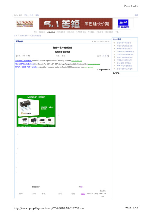
600
250/500
Yes
IRF6607
600
250/500
Yes
IRF7309 TRPBF
SOP-8
30V,N+P 400V,1000
600
2500/2500
Yes
IRF730PBF
TO-220AB mO,5.5A 74W
600
2500/2500
Yes
/html/s234/2010-10/512238.htm
IRF1404PBF
TO-221AB
IRF1404Z
TO-222AB
IRF1405PBF
TO-223AB
IRF1407
TO-224AB
IRF2804
TO-225AB
IRF2807PBF
TO-226AB
IRF3205PBF
TO-227AB
IRF3205SPBF IRF3415 IRF3808
TO-228AB TO-229AB TO-230AB
2011-5-10
Page 2 of 6
High Side IR2010PBF and Low Side High Side IR2010SPBF and Low Side High Side IR2011PBF and Low Side High Side IR2011SPBF and Low Side IR20153SPBF Single Channel 150 High Side IR2101PBF and Low Side High Side IR2101S and Low Side High Side IR2101SPBF and Low Side IR2103SPBF IR2104SPBF IR2104STR Half Bridge Half Bridge Half Bridge High Side IR2106SPBF and Low Side IR21084 Half Bridge 600 600 600 200/350 200/350 200/350 Yes Yes 600 200/350 600 600 600 210/360 210/360 210/360 Yes Yes 600 210/600 600 210/600 600 210/600 400/1500 Yes 200 1000/1000 200 1000/1000 200 3000/3000 Yes 200 3000/3000 Yes
FLIR热成像仪选型指南说明书

FLIR THERMAL IMAGING CAMERA SELECTION GUIDEFLIR THERMAL CAMERA MATRIXCORPORATE HEADQUARTERS FLIR Systems, Inc.27700 SW Parkway Ave.Wilsonville, OR 97070USAPH: +1 866.477.3687NASHUAFLIR Systems, Inc.9 Townsend West Nashua, NH 06063USAPH: +1 603.324.7611LATIN AMERICA FLIR Systems BrasilAv. Antonio Bardella, 320Sorocaba, SP 18085-852BrasilPH: +55 15 3238 7080CANADAFLIR Systems, Ltd.920 Sheldon CourtBurlington, ON L7L 5K6CanadaPH: +1 800.613.0507EUROPEFLIR SystemsLuxemburgstraat 22321 Meer BelgiumPH : +32 (0) 3665 5100UNITED KINGDOM FLIR Systems UK2 Kings Hill Av. - Kings Hill West Malling KentME19 4AQUnited KingdomTel. : +44 (0)1732 220 011CHINAFLIR Systems Co., Ltd Rm 1613-16, Tower II Grand Central Plaza 138 Shatin Rural Committee Rd.Shatin, New Territories Hong KongPH: +852 2792 8955Specifications are subject to change without notice©Copyright 2018, FLIR Systems, Inc. All other brand and product names are trademarks of their respective owners. The images displayed may not be representative of the actual resolution of the camera shown. Images for illustrative purposes only. (Created 02/18)18-1805-INS/instruments NASDAQ: FLIRElectrical cabinet inspections can be dangerous, requiring layers of heavy, protective clothing just to conduct a few minutes of scans. IR Windows can reduce the need for Personal Protective Equipment (PPE) or eliminate it by providing a safe way to inspect electrified equipment from the outside.FLIR Tools™, FLIR Tools+, and the FLIR Tools mobile app are designed to provide an easy way to upload content, share it, and create inspection reports. This software allows you to change image settings, add new temperature points, analyze data, and create standardized reports. FLIR also offers a new workflow management tool for your smart device called FLIR InSite™. This inspection management application can help you plan and prepare for inspections, collect inspection data, and deliver those results to your team or clients through a secure portal.FLIR offers a complete line of test and measurement equipment, from clamp and digital multimeters to borescopes and moisture meters. Built upon FLIR’s commitment to innovation, these tools help you diagnose problems and get right to repairs. Look formeters featuring IGM™ (Infrared Guided Measurement) to help you quickly identify the location of potential problems.The Infrared Training Center (ITC) offers a wide variety of thermography classes to prepare you to take a leadership role in an infrared inspection program. Register for online courses, watch free seminars, or sign up for classes at locations around the country. You can also schedule o n-site training for your facility. For a complete list of courses and current schedule, visit or call 1.866.872.4647.FLIR IR WINDOWSREPORTING SOFTWAREFLIR TEST & MEASUREMENTINFRARED TRAINING CENTER。
保险丝选型指南
(一)保险丝选择因素1.额定电流保险丝的额定电流是:指它的公称额定电流, 通常就是电路能够长期工作的最大电流值,而不是动作电流。
UL 规格保险丝过载能力弱,保险丝额定电流需按折减率0.75后使用。
IEC 规格保险丝过载能力强,额定电流不需折减。
选择原则:在25℃条件运行时,熔丝的电流额定值通常要减少25%以避免干扰熔断。
对于工作温度高于25℃的,需例 如:电路工作电流Ir=1.5A,UL保险丝额定电流应大于(或等于):Ir/Of=1.5A/0.75=2A (PS:Of为电流折减2.额定电压保险丝的额定电压是:指它的公称额定电压, 通常就是保险丝断开后能够承受的最大电压值。
保险丝通电时两端所承受的电压远小于其额定电压,因此额定电压基本上无关紧要。
关于保险丝选择原则:保险丝额定电压应该大于或等于电路工作电压。
例 如:250V的保险丝可以用于 125V的电路。
3.工作温度不管UL还是IEC规格,保险丝各项指标都是在25℃环境的数据。
如果小环境工作温度较高,则要考虑温度折减率(见选择原则:电路工作电流需小于(或等于):保险丝额定电流*0.75*K例 如:选用快熔断保险丝在90℃小环境下和1.5A电流下工作,参阅图1,其温度折损率(Tf)是95%。
①若选用IEC规格保险丝:In/Tf=1.5/0.95=1.58A,推荐1.6A或2A的保险丝。
②若选用UL规格保险丝:In/(Of*Tf)=1.5/(0.75*0.95)=2.1A,推荐2.5A的保险丝。
曲线 A: 传统的慢熔断保险丝曲线 A: 传统的慢熔断保险丝曲线 B: 特快熔断, 快熔断和螺旋式绕制的保曲线 B: 特快熔断, 快熔断和螺旋式绕制的保险丝图1 温度折减率与温度关系曲线 C: 可恢复 PTC曲线 C: 可恢复 PTC4.电压降/冷电阻--Ud/R①一般情况,保险丝的电阻值与它的额定电流值成反比。
②在保护电路中要求保险丝阻值越小越好,这样它的损耗功率就小,因此在保险丝技术参数中规定了最大电压降值或冷电阻值,但不作为产品验收依据。
ir型号命名规则

ir型号命名规则在产品设计和开发过程中,型号命名规则是非常重要的。
适当的命名规则可以帮助企业和消费者更好地区分产品,提高产品的辨识度和市场竞争力。
下面是一些常见的IR型号命名规则的参考内容。
1. 前缀标识法:在型号命名中添加一个独特的前缀来区分不同的产品系列。
例如,可以使用字母A表示某一系列产品,B表示另一系列产品,依此类推。
这样的命名规则可以使不同产品系列在名称上有明显区分,易于消费者识别。
2. 功能标识法:根据产品的主要功能来命名。
例如,如果产品主要用于红外线传输,可以在型号中添加字母"IR";如果产品具有特殊的功能或技术创新,可以在型号中加入相应的标识,如"HD"表示高清,"4K"表示超高清等。
3. 数字序列法:使用数字来表示不同产品之间的差异和级别。
例如,可以使用1、2、3等数字来表示低、中、高级产品。
这种命名规则直观且易于理解,消费者可以根据数字来判断产品在价格和性能上的差异。
4. 单词组合法:将几个关键词或描述性词汇组合在一起,以便更好地描述产品的特点和用途。
例如,可以将产品的功能、尺寸、用途等关键信息组合在一起,如"IRHD5K"表示具有高清并支持4K分辨率的红外线设备。
5. 区域标识法:根据产品销售的地区进行命名。
例如,使用地区的缩写或代号作为型号的一部分,以便更好地区分不同地区销售的产品。
这样可以方便企业在市场推广和销售方面进行针对性的策略。
6. 时间序列法:根据产品发布或上市的时间顺序进行命名。
这种命名规则可以帮助消费者了解产品的新旧程度和更新换代情况。
例如,可以在型号中添加年份或季度,如"IR2022"表示2022年发布的红外线产品。
型号命名规则的选择应根据公司的实际情况和市场需求来确定。
无论选择哪种命名规则,都应保证命名的简洁明了,易于理解和识别。
此外,命名规则应与产品的特点和品牌形象相符合,以便加强产品的市场认知度和竞争力。
电力载波产品选型指南
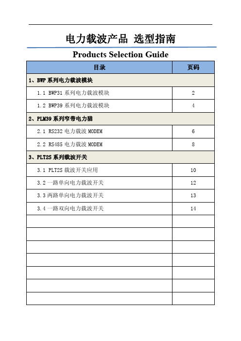
电力载波产品选型指南BWP31系列电力载波模块一、主要性能特点●工作电源:+12VDC+5VDC。
●接口类型:TTL电平串行接口(UART),半双工。
●传输类型:完全的透明数据传输,全集成。
●串口(UART)速率:9600bps,可接受客户定制。
●载波(PLC)速率:180bps、360bps、2400bps、5400bps可由用户配置。
●传输模式:固定帧长度传输(定帧模式)与固定字节长度传输(定长模式)。
●工作环境:交流220VAC/110VAC,50/60Hz,直流300VDC以下,无电导体。
●通讯距离:大于500m,(轻负载条件或者直流线路情况下,通讯距离大于1000m)。
●电力线载波频率:132KHz、264KHz、312KHz、416KHz四种频率可选。
●调制解调方式:BPSK+DSSS(直序扩频)。
●工作温度:-40℃~+80℃二、外形尺寸三、端口定义数据接口功能定义BWP31电力载波模块的数据接口采用单排8PIN接口,分别对应电源接口、通讯接口与信号接口,具体定义如下。
接口符号定义方向1+V+12VDC电源(>6W)输入2G电源地输入3+5+5VDC电源(>0.5W)输入4P1TX发送指示(选用功能)输出5P2RX接收指示(选用功能)输出6R RXD,串口数据输入模块输入7T TXD,串口数据输出模块输出8P3RESET复位输入,低电平有效输入五、选型指南序号型号载波频率载波速率串口速率1BWP31A132KHz180bps360bps2400bps5.4Kbps用户可配置9600bps1位起始位,8位数据位,1位停止位,无校验2BWP31B264KHz3BWP31C312KHz4BWP31D416KHz备注:载波模块有多余IO口引出,可进行功能定制,详情请与相应销售人员联系。
BWP39系列电力载波模块一、主要性能特点●工作电源:+12VDC+5VDC。
●接口类型:TTL电平串行接口(UART),半双工。
海格产品选型手册

海格电气选型手册2010/20112HWH 406P F LSI分断能力:H: 55 KA (框架 I, 630A~1600A)极数:3: 三极 4: 四极额定电流:06: 630 A 08: 800 A 10: 1000 A12: 1250 A 16: 1600 AF: 固定式D: 抽出式P: 中国市场编号保护控制器类型:LS LSILSIGLCD HWH 系列标准配置空气断路器型号含义标准配置的55kA 3极1250A 三段保护的抽出式空气断路器:编号:HWH312PDLSI选型实例:• 断路器本体已包含4NO+4NC 辅助触点;• 标准配置抽出式空气断路器具备以下配置:断路器本体、抽架、安全档板、摇柄、密封门框、失配保护、控制器、合闸继电器、分励继电器、储能电机,端子适配器;• 标准配置固定式空气断路器具备以下配置:断路器本体、支架、密封门框、控制器、合闸继电器、分励继电器、储能电机,密封门框。
* 产品系列范围请查看参数表3 HW N406P F+LSI附件分断能力:N: 65 kA (框架 I, 630A~1600A)80 kA (框架 III, 3200A~4000A)S: 80 kA (框架 II, 2000A~2500A)P: 100 kA (框架 III, 3200A~4000A)极数:3: 三极 4: 四极额定电流:06: 630 A 20: 2000A08: 800 A 25: 2500A10: 1000 A 32: 3200A12: 1250 A 40: 4000A16: 1600 AF: 固定式D: 抽出式P: 中国市场编号保护控制器类型:LSLSLCDLSILSILCDLSIGLSIGLCD可选附件:UVR:欠压继电器CFI:故障指示触点OL:OFF按钮锁附件及其它需求可使用中文标注HWN/S/P系列标准配置空气断路器设计型号含义65kA 3极1250A三段保护带液晶显示屏的抽出式空气断路器 + 欠压继电器:标注:HWN312PDLSILCD + 欠压继电器(或UVR)设计选型实例:•断路器本体已包含4NO+4NC辅助触点;•本设计型号的抽出式空气断路器已具备以下配置:断路器本体、抽架、安全档板、摇柄、密封门框、失配保护、控制器、合闸继电器、分励继电器、储能电机,端子适配器;•本设计型号的固定式空气断路器已具备以下配置:断路器本体、支架、密封门框、控制器、合闸继电器、分励继电器、储能电机,密封门框。
自举电容的选择ir2110
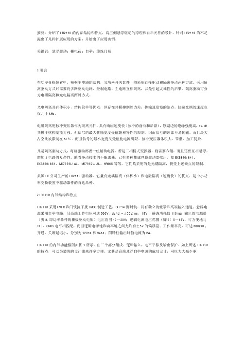
摘要:介绍了IR2110的内部结构和特点,高压侧悬浮驱动的原理和自举元件的设计。
针对IR2110的不足提出了几种扩展应用的方案,并给出了应用实例。
关键词:悬浮驱动;栅电荷;自举;绝缘门极1引言在功率变换装置中,根据主电路的结构,其功率开关器件一般采用直接驱动和隔离驱动两种方式。
采用隔离驱动方式时需要将多路驱动电路、控制电路、主电路互相隔离,以免引起灾难性的后果。
隔离驱动可分为电磁隔离和光电隔离两种方式。
光电隔离具有体积小,结构简单等优点,但存在共模抑制能力差,传输速度慢的缺点。
快速光耦的速度也仅几十kHz。
电磁隔离用脉冲变压器作为隔离元件,具有响应速度快(脉冲的前沿和后沿),原副边的绝缘强度高,dv/dt 共模干扰抑制能力强。
但信号的最大传输宽度受磁饱和特性的限制,因而信号的顶部不易传输。
而且最大占空比被限制在50%。
而且信号的最小宽度又受磁化电流所限。
脉冲变压器体积大,笨重,加工复杂。
凡是隔离驱动方式,每路驱动都要一组辅助电源,若是三相桥式变换器,则需要六组,而且还要互相悬浮,增加了电路的复杂性。
随着驱动技术的不断成熟,已有多种集成厚膜驱动器推出。
如EXB840/841、EXB850/851、M57959L/AL、M57962L/AL、HR065等等,它们均采用的是光耦隔离,仍受上述缺点的限制。
美国IR公司生产的IR2110驱动器。
它兼有光耦隔离(体积小)和电磁隔离(速度快)的优点,是中小功率变换装置中驱动器件的首选品种。
2IR2110内部结构和特点IR2110采用HVIC和闩锁抗干扰CMOS制造工艺,DIP14脚封装。
具有独立的低端和高端输入通道;悬浮电源采用自举电路,其高端工作电压可达500V,dv/dt=±50V/ns,15V下静态功耗仅116mW;输出的电源端(脚3,即功率器件的栅极驱动电压)电压范围10~20V;逻辑电源电压范围(脚9)5~15V,可方便地与TTL,CMOS电平相匹配,而且逻辑电源地和功率地之间允许有±5V的偏移量;工作频率高,可达500kHz;开通、关断延迟小,分别为120ns和94ns;图腾柱输出峰值电流为2A。
- 1、下载文档前请自行甄别文档内容的完整性,平台不提供额外的编辑、内容补充、找答案等附加服务。
- 2、"仅部分预览"的文档,不可在线预览部分如存在完整性等问题,可反馈申请退款(可完整预览的文档不适用该条件!)。
- 3、如文档侵犯您的权益,请联系客服反馈,我们会尽快为您处理(人工客服工作时间:9:00-18:30)。
— √ √ √ √ √ √ √ √ √ √ — — — —
— — — 16L DIP 16LSOIC
10
IR21592
√ — √ √ —
1.8μS √ — √ √ — √ √ √ √ √ √ √ — —
— — — 16L DIP, 16L SOIC
IR21593
√ — √ √ —
1.0μS √ — √ √ — √ √ √ √ √ √ √ — —
特
性
非反相输入,内置上拉/下拉,兼容 15V 逻辑 反相输入,内置上拉/下拉,兼容 15V 逻辑 电流感应,过流检测,关断故障输出 电流感应,过流故障信号 限流,关断错误脚可编程 过流检测关断,非反相输入,反相故障输出,兼容 3.3V,5V,15V 逻辑 同 IR2127,更低的低压门限 同 IR2127,反相输入
带 600V 半桥栅极驱动器的镇流器控制 IC 应用:照明
可编程性 预热时间 预热频率
闭环预热电流 运行频率 死区时间
特性 固定死区时间 过流保护 欠流保护 故障-击穿保护 灯丝开路 低谐振保护 暗光保护 自动重启动 热过载保护 关断 Pin 可调过流 可调光 启动检测 故障计数器 灯寿保护
集成 半桥 MOSFETs 自举二极管 功率因数校正
IR2520D
√ — — √ —
1.8μS √ — √ √ — — √ — — √ — — — —
— — — 8L DIP 8L SOIC
参考设计套件 全部安装、测试和文件(包括原理图、应用笔记、BOM、和 Gerber 文件) 应用:照明
参考设计套件料号 IRPLCFL2
镇流器 IC IR2156
10-25V(低压关断) 10-25V(低压关断) 10-25V(低压关断) 10-25V(低压关断) 10-25V(低压关断) 10-25V(低压关断)
13
贝能科技 IR 产品选型指南
传输匹配 最大 15ns 最大 50ns 最大 50ns 最大 30ns 最大 50ns 最大 10ns
特
性
操作频率可达 1MHz
2005 福建贝能科技有限公司
12
高端和低端驱动器 应用:照明,电源,电机驱动,D 类音频放大器和等离子平板显示器
型号
封装
Vs
输出源/吸收电流
Vcc 范围
IR2010 IR2010S
14L PDIP 16L SOIC
200V
+3.0/-3.0A
10-25V(低压关断)
IR2101 IR2101S IR2102 IR2102S
最小 200ns
同 IR2136,高端不反相,更高的低压关断门限值
同 IR2136,同相输入,独立的高]低端输入
最小 200ns
全部反相输入,独立的高、低端输入,低压关断所有驱动器,内置过流比较器,锁存故 障逻辑,故障清除输入,同步关断输入
特
性
三相驱动,反相输入
三相驱动,反相输入,独立的高端和低端
三相驱动,反相输入
最小 200ns
全部反相输入,独立的高、低端输入,低压关断所有驱动器,内置过流比较器,锁存故 障逻辑,故障清除输入,同步关断输入
IR2133 的低电流输出版本,3.3V 或 5V 反相输入逻辑,可编程故障清除延迟,软启动驱 动器
10-25V(低压关断) 10-25V(低压关断)
IR2127/S
600V
+200/-420m A
10-25V(低压关断)
IR21271/S
600V
+200/-420m A
10-25V(低压关断)
IR2128/S
600V
+200/-420m A
10-25V(低压关断)
VBS 范围 10-25V(低压关断) 10-25V(低压关断) 10-20V(低压关断) 10-20V(低压关断) 12-18V(低压关断) 12-25V(低压关断) 9-25V(低压关断) 12-25V(低压关断)
高、低端驱动器,非反相输入
高、低端驱动器,非反相输入
软启动,非反相输入,兼容 3.3V,5V 和 15V 逻辑
同 IR2106,另外,所有高压脚在一边,逻辑地和功率地隔离
非反相输入,5-20V 单独的逻辑电源,关断输入
软启动,非反相输入,兼容 3.3V,5V 和 15V 逻辑 同 IR2181,另外,所有高压脚在一边,逻辑地和功率地隔离
SOIC
MOSFET 和 IGBT 的栅极驱动 IC
输出源/吸收电流 +1.0/-2.0A
输出源/吸收电流 +1.5/-1.5A
Vcc 范围 10-25V(低压关断)
VBS 范围 12-18V
传输延迟 150ns ton
Vcc 范围 6-20V
VBS 范围
传输延迟
6-20V
85ns ton 65ns toff
+200/-420m A
10-25V(低压关断)
IR2118/S
600V
+200/-420m A
10-25V(低压关断)
IR2122
600V
+110/-110mA
10-25V(低压关断)
IR2122S IR2125/S
8L PDIP 8L SOIC
600V 500V
+110/-110mA +1.0/-2.0A
贝能科技 IR 产品选型指南
特性 过流限制,关断时间可编程,故障条件信号
特性 双低端驱动器,反相输入
双低端驱动器 双低端驱动器,一半反相输入
高压栅极驱动 IC 高端驱动器 应用:照明,电源,电机驱动,D 类音频放大器和等离子平板显示器
型号
封装
Vs
输出源/ 吸收电流
Vcc 范围
IR2117/S
600V
— — — 16L DIP, 16L SOIC
IR2166
√ — √ √ √
— √ — √ √ — √ √ — √ √ — — √ √
— — √ 16L DIP, 16L SOIC
贝能科技 IR 产品选型指南
IR2167
√ — — √ √
— √ √ √ √ √ √ √ √ √ √ — — √ √
— — √ 16L DIP, 16L SOIC
IR2112 IR2112-1 IR2112-2 IR2112S
14L PDIP 14L SOIC 16L PDIP 16L SOIC
600V
+200/-420m A
10-25V(低压关断)
IR2181 IR2181S IR21814
8L PDIP 8L SOIC 14L PDIP
600V
+1.4/-1.8A
传输延迟
ton125ns/toff105ns ton125ns/toff105ns ton250ns/toff200ns ton250ns/toff200ns ton150ns/toff150ns ton200ns/toff150ns ton200ns/toff150ns ton200ns/toff150ns
封装
IR2153
— — — √ —
1.2μS — — — — — — — — — — — — — —
— — — 8L DIP 8L OIC
IR53H420
— — — √ —
1.2μS — — — — — — — — — — — — — —
3Ω — — 9L SIP w/o 2L
2005 福建贝能科技有限公司
+160/-360m A
10-20V (低压关断)
600V 600V 1200V
+200/-420m A +120/-250m A +200/-420m A
10-25V (低压关断)
12-25V (低压关断)
10-25V (低压关断)
12-25V (低压关断)
12-20V (低压关断)
10-25V (低压关断)
照明电子镇流器控制 IC
IR64HD420
— — — √ —
1.2μS — — — — — — — — — — — — — —
3Ω √ — 9L SIP w/o 2L
IR2156
— — — √ √
— √ — √ √ — √ √ — √ √ — — — —
— — — 14L DIP 14 SOIC
IR21571
42W,单管,紧凑型荧光灯镇流器,110/220VAC
描ቤተ መጻሕፍቲ ባይዱ
述
IRPLCFL3 IRPLLNR2E IRPLLNR2U IRPLDIM1E
IR2156 IR21571 IR21571 IR21592
双向可控硅调光电路,27W,单管,小型荧光灯镇流器,120VAC 36W 全集成线型灯光镇流器,欧洲版,230VAC,36W/T8 灯管 32W 全集成线型灯光镇流器,美国版,120VAC,32W/T8 灯管 调光照明镇流器,欧洲版,230VAC,36W/T8 灯管
IRPLMB1E
IR2520D
25W 荧光灯紧凑型电子镇流器,欧洲版 25W
贝能科技 IR 产品选型指南
2005 福建贝能科技有限公司
11
应用:照明,电源,电机驱动 低端驱动器
型号
封装
Vs
IR2121
8L PDIP
5V
双低端驱动器
型号
封装
Vs
IR4426/S IR4427/S IR4428/S
8L PDIP, 20V
14L PDIP 14L SOIC 16L PDIP 16L SOIC
600V
+2.0/-2.0A
