XS1110-SPEC单组份
服务器Spec值

服务器Spec值服务器Spec值===============1、介绍-----------本文档旨在提供服务器技术规范的详细信息和指导,以便于正确配置和管理服务器。
以下是服务器Spec值的详细信息。
2、硬件规格--------------2.1 服务器型号--------------服务器型号:[请输入服务器型号]2.2 处理器-----------2.2.1 型号--------------处理器型号:[请输入处理器型号]2.2.2 核心数--------------处理器核心数:[请输入处理器核心数量] 2.2.3 频率--------------处理器频率:[请输入处理器频率]2.2.4 缓存大小--------------处理器缓存大小:[请输入处理器缓存大小] 2.3 内存-----------2.3.1 容量--------------内存容量:[请输入内存容量]2.3.2 类型--------------内存类型:[请输入内存类型]2.4 硬盘-----------2.4.1 容量--------------硬盘容量:[请输入硬盘容量]2.4.2 接口类型--------------硬盘接口类型:[请输入硬盘接口类型] 2.4.3 转速--------------硬盘转速:[请输入硬盘转速]3、软件规格-------------3.1 操作系统-------------操作系统版本:[请输入操作系统版本] 3.2 数据库管理系统------------------数据库管理系统:[请输入数据库管理系统名称] 3.3 网络协议------------网络协议:[请输入网络协议]4、网络规格-------------4.1 IP地质--------------IP地质:[请输入服务器的IP地质]4.2 带宽--------------带宽:[请输入服务器的带宽]5、安全规范-------------5.1 防火墙--------------防火墙设置: [请输入防火墙设置] 5.2 安全认证--------------安全认证: [请输入安全认证设置] 6、性能规范-------------6.1 响应时间--------------响应时间:[请输入服务器的响应时间] 6.2 吞吐量--------------吞吐量:[请输入服务器的吞吐量]7、附件---------本文档涉及附件:- [附件1:服务器型号详细规格]- [附件2:处理器型号说明书]- [附件3:内存规格说明书]8、法律名词及注释-----------------在本文档中,以下法律名词和注释适用:- 法律名词1:注释- 法律名词2:注释。
SiLabs CP2101单芯片USB到UART桥数据手册说明书
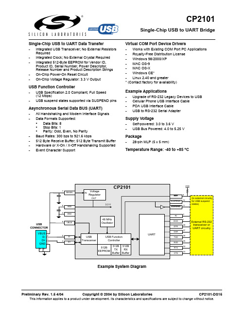
Single-Chip USB to UART BridgeCP2101Single-Chip USB to UART Data Transfer-Integrated USB Transceiver; No External Resistors Required-Integrated Clock; No External Crystal Required -Integrated 512-Byte EEPROM for Vendor ID, Product ID, Serial Number, Power Descriptor, Release Number and Product Description Strings -On-Chip Power-On Reset Circuit-On-Chip Voltage Regulator: 3.3 V OutputUSB Function Controller-USB Specification 2.0 Compliant; Full Speed (12 Mbps)-USB suspend states supported via SUSPEND pinsAsynchronous Serial Data BUS (UART)-All Handshaking and Modem Interface Signals -Data Formats Supported:•Data Bits: 8•Stop Bits: 1•Parity: Odd, Even, No Parity -Baud Rates: 300 bps to 921.6 kbps-512 Byte Receive Buffer; 512 Byte Transmit Buffer -Hardware or X-On / X-Off Handshaking Supported -Event Character SupportVirtual COM Port Device Drivers-Works with Existing COM Port PC Applications -Royalty-Free Distribution License -Windows 98/2000/XP -MAC OS-9-MAC OS-X -Windows CE*-Linux 2.40 and greater* (Contact factory for availability)Example Applications-Upgrade of RS-232 Legacy Devices to USB -Cellular Phone USB Interface Cable -PDA USB Interface Cable -USB to RS-232 Serial Adapter Supply Voltage-Self-powered: 3.0 to 3.6 V-USB Bus Powered: 4.0 to 5.25 V Package-28-pin MLP (5 x 5 mm)Temperature Range: -40 to +85 °CCP2101Table of Contents1.System Overview (4)2.Absolute Maximum Ratings (4)Table 2.1. Absolute Maximum Ratings (4)3.Global DC Electrical Characteristics (5)Table 3.1. Global DC Electrical Characteristics (5)Table 3.2. UART and Suspend I/O DC Electrical Characteristics (5)4.Pinout and Package Definitions (6)Table 4.1. Pin Definitions for the CP2101 (6)Figure 4.1. MLP-28 Pinout Diagram (Top View) (7)Figure 4.2. MLP-28 Package Drawing (8)Table 4.2. MLP-28 Package Dimensions (8)Figure 4.3. Typical MLP-28 Landing Diagram (9)Figure 4.4. Typical MLP-28 Solder Mask (10)B Function Controller and Transceiver (11)Figure 5.1. Typical Connection Diagram (11)6.Asynchronous Serial Data Bus (UART) Interface (12)Table 6.1. Data Formats and Baud Rates (12)7.Internal EEPROM (12)Table 7.1. Default USB Configuration Data (12)8.Virtual Com Port Device Drivers (13)9.Voltage Regulator (14)Table 9.1. Voltage Regulator Electrical Specifications (14)Figure 9.1. Configuration 1: USB Bus-Powered (14)Figure 9.2. Configuration 2: USB Self-Powered (15)Figure 9.3. Configuration 3: USB Self-Powered, Regulator Bypassed (15)1.System OverviewThe CP2101 is a highly-integrated USB-to-UART Bridge Controller providing a simple solution for updating RS-232 designs to USB using a minimum of components and PCB space. The CP2101 includes a USB 2.0 full-speed function controller, USB transceiver, oscillator, EEPROM and asynchronous serial data bus (UART) with full modem control signals in a compact 5 x 5 mm MLP-28 package. No other external USB components are required.The on-chip EEPROM may be used to customize the USB Vendor ID, Product ID, Product Description String, Power Descriptor, Device Release Number and Device Serial Number as desired for OEM applications. The EEPROM is programmed on-board via the USB allowing the programming step to be easily integrated into the product manufacturing and testing process.Royalty-free Virtual COM Port (VCP) device drivers provided by Silicon Laboratories allow a CP2101-based product to appear as a COM port to PC applications. The CP2101 UART interface implements all RS-232 signals, including control and handshaking signals, so existing system firmware does not need to be modified. In many existing RS-232 designs, all that is required to update the design from RS-232 to USB is to replace the RS-232 level-translator with the CP2101.An evaluation kit for the CP2101 (Part Number: CP2101EK) is available. It includes a CP2101-based USB-to-UART/RS-232 evaluation board, a complete set of VCP device drivers, USB and RS-232 cables, and full documentation. Contact a Silicon Labs’ sales representatives or go to to order the CP2101 Evaluation Kit.2.Absolute Maximum RatingsTable 2.1. Absolute Maximum RatingsParameter Conditions Min Typ Max Units Ambient temperature under bias–55—125°C Storage Temperature–65—150°C Voltage on any I/O Pin or RST with respect to–0.3— 5.8V GNDVoltage on V DD with respect to GND–0.3— 4.2V Maximum Total current through V DD and GND——500mA——100mA Maximum output current sunk by RST or anyI/O pinNote: stresses above those listed under “Absolute Maximum Ratings” may cause permanent damage to the device. This is a stress rating only and functional operation of the devices at those or any other condi-tions above those indicated in the operation listings of this specification is not implied. Exposure to maxi-mum rating conditions for extended periods may affect device reliability.CP21013.Global DC Electrical CharacteristicsTable 3.1. Global DC Electrical CharacteristicsV DD = 2.7 to 3.6 V, –40 to +85 °C unless otherwise specifiedParameter Conditions Min Typ Max Units Supply Voltage 3.0 3.3 3.6V Supply Current V DD = 3.3 V—25—mA Supply Current in Suspend V DD = 3.3 V—325—µA Specified Operating Temperature Range–40—+85°CTable 3.2. UART and Suspend I/O DC Electrical CharacteristicsV DD = 2.7 to 3.6 V, -40 to +85 °C unless otherwise specifiedParameters Conditions Min Typ Max UNITSOutput High Voltage I OH = -3mAI OH = -10µAI OH = -10mAVDD-0.7VDD-0.1VDD-0.8VOutput Low Voltage I OL = 8.5mAI OL = 10µAI OL = 25mA 1.00.60.1VInput High Voltage 2.0V Input Low Voltage0.8V Input Leakage Current2550µACP21014.Pinout and Package DefinitionsTable 4.1. Pin Definitions for the CP2101Name Pin #Type DescriptionV DD6Power InPowerOut3.0–3.6 V Power Supply Voltage Input.3.3 V Voltage Regulator Output. See Section 9.GND3GroundRST9 D I/O Device Reset. Open-drain output of internal POR or V DD monitor. An external source can initiate a system reset by driving this pin low for at least 15 µs.REGIN7Power In 5 V Regulator Input. This pin is the input to the on-chip voltage regu-lator.VBUS8 D In VBUS Sense Input. This pin should be connected to the VBUS signal of a USB network. A 5 V signal on this pin indicates a USB network connection.D+4 D I/O USB D+D–5 D I/O USB D–TXD26 D Out Asynchronous data output (UART Transmit) RXD25 D In Asynchronous data input (UART Receive) CTS23* D In Clear To Send control input (active low)RTS24* D Out Ready to Send control output (active low)DSR27* D in Data Set Ready control input (active low)DTR28* D Out Data Terminal Ready control output (active low) DCD1* D In Data Carrier Detect control input (active low)RI2* D In Ring Indicator control input (active low)SUSPEND12* D Out This pin is driven high when the CP2101 enters the USB suspend state.SUSPEND11* D Out This pin is driven low when the CP2101 enters the USB suspend state.NC10, 13–22These pins should be left unconnected or tied to V DD. *Note: Pins can be left unconnected when not used.CP2101Figure 4.1. MLP-28 Pinout Diagram (Top View)CP2101Figure 4.2. MLP-28 Package DrawingTable 0.1. MLP-28 Package DimensionsMM MIN TYP MAX A 0.800.90 1.00A100.020.05A200.65 1.00A3—0.25—b 0.180.230.30D — 5.00—D2 2.90 3.15 3.35E — 5.00—E2 2.90 3.15 3.35e —0.5—L 0.450.550.65N —28—ND —7—NE —7—R 0.09——AA —0.435—BB —0.435—CC —0.18—DD—0.18—CP2101Figure 4.3. Typical MLP-28 Landing DiagramCP2101Figure 4.4. Typical MLP-28 Solder Mask11Rev. 1.5B Function Controller and TransceiverThe Universal Serial Bus function controller in the CP2101 is a USB 2.0 compliant full-speed device with integrated transceiver and on-chip matching and pull-up resistors. The USB function controller manages all data transfers between the USB and the UART as well as command requests generated by the USB host controller and commands for controlling the function of the UART.The USB Suspend and Resume signals are supported for power management of both the CP2101 device as well as external circuitry. The CP2101 will enter Suspend mode when Suspend signaling is detected on the bus. On entering Suspend mode, the CP2101 asserts the SUSPEND and SUSPEND signals. SUSPEND and SUSPEND are also asserted after a CP2101 reset until device configuration during USB Enumeration is completeThe CP2101 exits the Suspend mode when any of the following occur: (1) Resume signaling is detected or generated, (2) a USB Reset signal is detected, or (3) a device reset occurs. On exit of Suspend mode, the SUSPEND and SUSPEND signals are de-asserted.Both SUSPEND and SUSPEND temporarily float high during a CP2101 reset. If this behavior is undesirable, a strong pulldown (10 kΩ) can be used to ensure SUSPEND remains low during reset. See Figure 5.1 for other recommended options.Figure 5.1. Typical Connection DiagramRev. 1.5126.Asynchronous Serial Data Bus (UART) InterfaceThe CP2101 UART interface consists of the TX (transmit) and RX (receive) data signals as well as the RTS, CTS, DSR, DTR, DCD and RI control signals. The UART supports RTS/CTS, DSR/DTR and X-On/X-Off handshaking.The UART is programmable to support a variety of data formats and baud rates. The data format and baud rate programmed into the UART is set during COM port configuration on the PC. The data formats and baud rates available are listed in Table 6.1.7.Internal EEPROMThe CP2101 includes an internal EEPROM that may be used to customize the USB Vendor ID, Product ID, Product Description String, Power Descriptor, Device Release Number and Device Serial Number as desired for OEM applications. Customization of the USB configuration data is optional. If the EEPROM is not programmed with OEM data, the default configuration data shown in Table 7.1 is used. However, a unique serial number is required for OEM applications in which it is possible for multiple CP2101-based devices to be connected to the same PC.The internal EEPROM is programmed via the USB. This allows the OEM's USB configuration data and serial number to be written to the CP2101 on-board during the manufacturing and testing process. A stand-alone utility for programming the internal EEPROM is available from Silicon Laboratories. A library of routines provided in the form of a Windows ® DLL is also available. This library can be used to integrate the EEPROM programming step into custom software used by the OEM to streamline testing and serial number management during manufacturing. The EEPROM has a typical endurance of 100,000 write cycles with a data retention of 100 years.Table 6.1. Data Formats and Baud RatesData Bits 8Stop Bits 1Parity Type None, Even, OddBaud Rates300, 600, 1200, 1800, 2400, 4800, 7200, 9600, 14400, 19200, 28800, 38400, 56000, 57600, 115200, 128000, 230400, 460800, 921600Table 7.1. Default USB Configuration DataName Value Vendor ID 10C4h Product IDEA60h Power Descriptor (Attributes)80hPower Descriptor (Max. Power)32h Release Number 0100hSerial Number0001 (63 characters maximum)Product Description String“CP2101 USB to UART Bridge Controller” (126 characters maximum)13Rev. 1.58.Virtual Com Port Device DriversThe CP2101 Virtual COM Port (VCP) device drivers allow a CP2101-based device to appear to the PC's application software as an additional COM port (in addition to any existing hardware COM ports). Application software running on the PC accesses the CP2101-based device as it would access a standard hardware COM port. However, actual data transfer between the PC and the CP2101 device is performed over the USB. Therefore, existing COM port applications may be used to transfer data via the USB to the CP2101-based device without modifying the application. Contact Silicon Laboratories for the latest list of supported operating systems.Note:The Silicon Laboratories VCP device drivers are required for device operation and are only distributed as part of the CP2101 Evaluation Kit (Part Number: CP2101EK). Contact any of Silicon Lab’s sales representatives or go to to order the CP2101 Evaluation Kit. The CP2101 drivers and programming utilities are subject to change without notice. Subscription to the website "Auto Email Alert" system for automatic notification of updates and the use of the "Product Update Registration" service is recommended.Rev. 1.5149.Voltage RegulatorThe CP2101 includes an on-chip 5-to-3 V voltage regulator. This allows the CP2101 to be configured as either a USB bus-powered device or a USB self-powered device. These configurations are shown in Figure 9.1 and Figure 9.2. When enabled, the 3 V voltage regulator output appears on the V DD pin and can be used to power external 3V devices. See Table 9.1 for the voltage regulator electrical characteristics.Alternatively, if 3 V power is supplied to the V DD pin, the CP2101 can function as a USB self-powered device with the voltage regulator disabled. For this configuration, it is recommended that the REGIN input be tied to the 3 V net to disable the voltage regulator. This configuration is shown in Figure 9.3.The USB max power and power attributes descriptor must match the device power usage and configuration. See application note “AN144: CP2101 Customization Guide” for information on how to customize USB descriptors for the CP2101.Note:It is recommended that additional decoupling capacitance (e.g., 0.1 µF in parallel with 1.0 µF) be provided on the REGIN input.Figure 9.1. Configuration 1: USB Bus-PoweredTable 9.1. Voltage Regulator Electrical Specifications–40 to +85 °C unless otherwise specifiedParameterConditionsMin Typ Max Units Input Voltage Range 4.0— 5.25V Output VoltageOutput Current = 1 to 100 mA*3.0 3.3 3.6V VBUS Detection Input Threshold 1.0 1.84.0V Bias Current—90TBDµA* The maximum regulator supply current is 100 mA.15Rev. 1.5Figure 9.2. Configuration 2: USB Self-PoweredFigure 9.3. Configuration 3: USB Self-Powered, Regulator BypassedRev. 1.516Document Change ListRevision 1.4 to Revision 1.5Updated Example System Diagram on page 1.Updated Table 3.1, “Global DC Electrical Characteristics,” on page 5.Added Table 3.2, “UART and Suspend I/O DC Electrical Characteristics,” on page 5 Added Table note to Table 4.1, “Pin Definitions for the CP2101,” on page 6 Added Figure 5.1. , "Typical Connection Diagram" on page 11Removed asterisk from the “Linux 2.40 and greater” bullet on page 117Rev. 1.5NotesRev. 1.518Contact InformationSilicon Laboratories Inc.4635 Boston Lane Austin, TX 78735Tel: 1+(512) 416-8500 Fax: 1+(512) 416-9669 Toll Free: 1+(877) 444-3032Email:********************** Internet: Silicon Laboratories and Silicon Labs are trademarks of Silicon Laboratories Inc.Other products or brandnames mentioned herein are trademarks or registered trademarks of their respective holdersThe information in this document is believed to be accurate in all respects at the time of publication but is subject to change without notice. Silicon Laboratories assumes no responsibility for errors and omissions, and disclaims responsibility for any consequences resulting from the use of information included herein. Additionally, Silicon Laboratories assumes no responsibility for the function-ing of undescribed features or parameters. Silicon Laboratories reserves the right to make changes without further notice. Silicon Laboratories makes no warranty, representation or guarantee regarding the suitability of its products for any particular purpose, nor does Silicon Laboratories assume any liability arising out of the application or use of any product or circuit, and specifically disclaims any and all liability, including without limitation consequential or incidental damages. Silicon Laboratories products are not designed, intended, or authorized for use in applications intended to support or sustain life, or for any other application in which the failure of the Silicon Laboratories product could create a situation where personal injury or death may occur. Should Buyer purchase or use Silicon Laboratories products for any such unintended or unauthorized application, Buyer shall indemnify and hold Silicon Laboratories harmless against all claims and damages.。
iWSN -1110X系列快速入门指南说明书

iWSN-1110X Series Quick Startv1.30, Apr 2019W hat’s in boxW ithout “Quick St art”, The package includes the following items:iWSN-1110X Series Module Split-core CTScrew Driver(1C016)Module Name Split-core CT Module Name Split-core CTiWSN-1110X Without CTiWSN-1110X-240 8m, Φ24mm (200A), 1 pcs iWSN-1110X-1608m, Φ16mm (100A), 1 pcsiWSN-1110X-3608m, Φ36mm (400A), 1 pcs1 AppearanceNumberInstructions1 Build in PCB antenna2DIP switch of power3 CT connection terminal4 Extension port5 Boot and wake button6 DIP switch of parameter setting 7LED indicators○1 ○3 ○4 ○6 ○7○5 ○22 Pin and buttonSwitch InstructionsPWRON Power onOFF Power offPin Name Instructions4 N/AReserved, empty orshorted3 N/A2 CT Split-core CT pin,nodirectionality,supportmeasuring andcharging function1 CTExtension bus InstructionsExt_Bus Empty or connect extension moduleButton Instructions Wake Manual wake upBoot After pressing for 1~3 seconds, the LED light will be on for 1 second and then off. This meanboot complete.3 Communication parameterName InstructionsF2Reserved F1TX Duty ( RF transmitduty )■:ON □:OFF PeriodPin5 6 1 sec □□10 sec ■□30 sec □■60 sec ■■RF Ch ( RF Channel) ■:ON□:OFF ChPinChPin1 2 3 4 1 2 3 40 □□□□8 □□□■1 ■□□□9 ■□□■2 □■□□ A □■□■3 ■■□□ B ■■□■4 □□■□ C □□■■5 ■□■□ D ■□■■6 □■■□ E □■■■7 ■■■□ F ■■■■Name Instructions PA Factory OnlyGID (Group ID) ■:ON □:OFF GroupPin6 70 □□1 ■□2 □■3 ■■Node ID■:ON □:OFF NodePinNodePin1 2 3 4 5 1 2 3 4 50 □□□□□16 □□□□■1 ■□□□□17 ■□□□■2 □■□□□18 □■□□■3 ■■□□□19 ■■□□■4 □□■□□20 □□■□■5 ■□■□□21 ■□■□■6 □■■□□22 □■■□■7 ■■■□□23 ■■■□■8 □□□■□24 □□□■■9 ■□□■□25 ■□□■■10 □■□■□26 □■□■■11 ■■□■□27 ■■□■■12 □□■■□28 □□■■■13 ■□■■□29 ■□■■■14 □■■■□30 □■■■■15 ■■■■□31 ■■■■■4 LED indicatorsThe module provides one LED indicator. The table below will show the LED status.5Boot stepsA. Please confirm the CT is locked into the module, and “Ext_Bus ” isconnected an extension module by audio line. (If there is no extensionmodule, the “Ext_Bus ” don ’t be connected.)B. Adjusting DIP switch and set the parameter of communication, and switch“PWR ” to OFF. And then switch “PWR ” to ON after press “Wake ” and “Boot ” buttons for 5 seconds.C. When power on, if “STA ” will light on for 1 second and off, this mean bootcomplete. If “STA ” do not be lighted, please press “Boot ” for 1~3 seconds, and confirm “STA ” will light on for 1 second and off. Finally, press “Wake ” once, confirm “STA ” blink once to complete the boot.D. Connect the CT to the cable to be measured. The buckle has nodirectionality, but after the buckle, you must confirm that the opening is completely closed.Before the CT be buckledAfter the CT be buckledConfirm the opening is completely closed○A ○B ○D ○CNote:1. if you need to remove the terminal lines, always detach the CT before removing the CT terminal lines. Otherwise the CT may develop open-circuit secondary voltages which may be hazardous to personnel or damaging to the CT or equipment connected in the secondary circuit.2.The external CT’s are fragile, please handle with care.3. The current input of the iWSN-1120X series only supports the factory-attached CT.4.To install CT’s correctly, please ensure the CT lines sequences is r ight before clip the CT’s onto the power cable of the monitoring equipment.5.Please select the appropriate size CT for different size monitoring equipment cables: power line diame ter <Φ24 using 200A CT, Φ36 using 400A CT.6.The maximum current value cannot exceed the CT rating.6 Application exampleThe module will measure the current data and transmit automatically to iWSN-2200 by wireless. The user can use computer to read the data in iWSN-2200 by Modbus RTU protocol.WarningICP DAS assumes no liability for any damage resulting from the use of this product. ICP DAS reserves the right to change this manual at any time without notice. The information furnished by ICP DAS is believed to be accurate and reliable. However, no responsibility is assumed by ICP DAS for its use, not for any infringements of patents or other rights of third parties resulting from its use.Limitation of WarrantyThis warranty does not apply to defects resulting from unauthorized modification, misuse, or use for reason other than electrical power monitoring. The supplied meter is not a user-serviceable product. Product Warranty & Customer SupportICP DAS warrants all products free from defects in material and workmanship for a period of one year from the date of shipping. During the warranty period, we will, at our position, either repair or replace any product that proves to be defective. To report any defect, please contact us. Please have the model, serial number and a detailed problem description available when you call. If the problem concerns a particular reading, please have all meter readings available. When returning any merchandise to ICP DAS, a return SN. Is required.。
嵌入式系统第四讲eeliod开发系统介绍

RW
ZI
EXEC_ROM 0x0 0x4000 { * (+RO) }
0x10000
0x4000
0x0000
0x18000
RO
RW
ZI
RO
CODE
RO -DATA
RO -CODE
A
B
链接器放置规则
在每个可执行区,链接器通过一些基本规则来放置CODE 和DATA,基本的排序方法是通过属性来安排的: RO 领先于RW ,RW 领先于ZI 有相同的属性时,CODE 在DATA之前放置。 更多的排序方法决定于: 输入的组名按字母排序, 在ARMLINK命令行中指定的顺序。 如: armlink file1.o file2.o …
Module板
另外还含有以下接口电路 音频控制接口电路——Philips UCB1400芯片,内含10bits的ADC LCD控制电路 触摸屏控制电路 通过两个120pin的连接器连接到EDR板
Module板
EDR板
PCMCIA/CF卡接口 MMC/SD卡接口 RTC——实时时钟 数码管和LED 按键 Sw1-sw4 直入键盘 Sw5-sw16矩阵扫描 Quick Capture摄像头模块——支持400万像素数码镜头,并能提供最大416Mbps的数据传输速率
PXA270
XSBase270开发平台
平台硬件分层
分EDR板(底板)和Module板(模块板或核心板) Module板 ——最小系统 EDR板 ——功能接口板
Module板
包含以下部分 MPU ——Intel Xscale PXA270 520MHz SDRAM ——双片,64M,缺省地址空间是0xa0000000 – 0xa3ffffff FLASH ——双片,32M,其缺省地址空间是0x00000000 – 0x01ffffff CPLD ——采用Xilinx公司的XC2C128可编程器件,丰富片选及加密 串口 ——全功能调试串口 网络接口 JTAG 电源控制——LP3971芯片,Intel SpeedStep动态电源管理技术
FS-1110操作手册(中文)

i
ii
法律和安全信息
请在使用本机之前阅读此信息。本章节介绍有关以下主题的信息:
法律和安全信息
4 保养 .......................................................................................................... 4-1 一般信息 .................................................................................................. 4-2 更换墨粉盒 .............................................................................................. 4-2 更换保养组件 .......................................................................................... 4-5 清洁打印机 .............................................................................................. 4-6 长期不使用和打印机的搬动 .................................................................. 4-9
FUJITSU Image Scanners SP系列产品说明书

FUJITSU Image ScannersSP-1120, SP-1125, SP-1130, SP-1425Future-proof. Simplified scanning opens doors for professional document capture Resourceful. Purpose built with impressive software suite for efficiency gains Reliable. Intuitively and dependably converts physical documents to digital formatConvenient. Simple and easy to use design, ideal for desktop placementRaise your productivityEasily evolve from your physical to electronic documents with the SP Series. Create one single reference source for all your data by merging paper documents with your digitally born documents. Gain the business advantages of working with more convenient, flexible and secure digital images using simple push button routines, the SP Series feature a simple operation panel with two buttons (Scan / Stop and Power).Store, retrieve and manage your documents more productively, efficiently and cost effectively than paper records allow. At the same time activelyembrace compliance risk avoidance concerns and increase your customer’s satisfaction.Cost effective high performance Achieve more in less time. Remove your backlog of documents and transform mixed batches of different thicknesses and sizes including plastic cards into high quality images. The SP Series has been especially designed to provide a simple but efficient paper to digital document scanning platform for all types of businesses looking to adopt a more systematic approach to regular document capture.Automatic size recognition and blank page removal simplifies scanning operations and pre scan sorting thereby helping to save theinconvenience of fine tuning the document for the OCR process. Fujitsu scanners are renowned for their highly reliable paper handling capabilities and these help remove image capture disruptions to reduce document management overheads.Desktop convenienceWith the ADF models measuring less than an A4 size sheet of paper the compact designtakes up minimal space on a busy desktop. The small footprint means these devices are always available and within reach for uninterrupted performance. Trade a small desktop space to reclaim a much larger space taken up by paper records. Whether it’ll be sets of loose sheets of documents scanned through all SP Series models’ automatic document feeders (ADFs) or bound materials that need to be scannedwith the SP-1425 flatbed module, the SP Seriesconveniently supports the user in regularly digitizing all office documents.PaperStream Capture Lite PaperStream Capture Lite is a powerful application used to scan documents with the SP Seriesscanner models. It is extremely easy-to-use and provides an interface similar to a mobile application. This allows users with little scanning experience to use the scanner almost instantly. PaperStream Capture Lite is based on the “One Click Capture” concept, which promotes reducing the number of times to touch the screen. It is effective in the prevention of operational errors as well as streamlining repeated operations. PaperStream Capture Lite presents itself as an essential capture tool for feeding TIF, BMP or JPEG files into defined capture routines by simply selecting a pictogram presented on screen.Bundled with business enhancing functionalityTurn lifeless business records into searchable, secure yet dynamic documents that can be fed into digital archives. The bundled version of ABBYY FineReader Sprint creates searchable and editable files from your paper documents allowing you to retrieve information more efficiently at a future date (the OCR processing can handle 190 languages). Call this application directly from within your PaperStream Capture Lite profile and searchable PDF and PDF/A files are just one click away.Presto PageManager offers further manifold possibilities for the enhancement, conversion and organisation of your personally used files.Faster throughput when it is neededThe SP Series models through their 50-sheet automatic document feeder (ADF) can process single or double sided pages at the same time. The SP-1120 can scan 20 A4 single sided pages per minute (ppm) or 40 images per minute (ipm), the SP-1125 and SP-1425 scan speeds are 25 ppm / 50 ipm and the SP-1130 scan speeds are 30 ppm / 60 ipm./scannersPFU (EMEA) Limited Hayes Park CentralHayes End Road, Hayes Middlesex UB4 8FE United KingdomPFU (EMEA) Limited Frankfurter Ring 21180807 Munich GermanyPFU (EMEA) Limited Viale Monza, 25920126 Milano (MI)ItalyPFU (EMEA) LimitedCamino Cerro de los Gamos, 128224 Pozuelo de Alarcón Madrid SpainTel: +44 (0)20 8573 4444Tel: +49 (0)89 32378 0Tel: +39 02 26294 1All indications are non-binding. Technical data is subject to change without prior notification.Bundled softwarePaperStream IP – high quality image enhancementPaperStream IP is the scanner driver for the SP Series. In addition to being fully compliant with the industry standard TWAIN and ISIS interface, PaperStream IP incorporates as standard, highly sophisticated image processing that automatically applies features such as noise removal, background pattern removal and character augmentation to produce exceptionally clear, high quality images that are suitable for direct import into the users’ workflow.PaperStream IP has an intuitive, easy to use interface that can be switched between Administrator or User mode to simplify the scanning process and reduce user error.Additionally PaperStream IP also introduces a new Assisted Scanning mode, which allows the user to visually select the best quality image from a range of images of the page, rather than needing to manually fine tune the scanning parameters one by one.Developed to be the best in class scanner driver。
西门子 NXGPro+ 控制系统手册_操作手册说明书
3.4
单元通讯的协议 ............................................................................................................ 36
3.5
NXGpro+ 高级安全 .......................................................................................................37
3.2
功率拓扑 ......................................................................................................................34
3.3
控制系统概述 ...............................................................................................................35
NXGPro+ 控制系统手册
NXGPro+ 控制系统手册
操作手册
AC
A5E50491925J
安全性信息
1
安全注意事项
2
控制系统简介
3
NXGPro+ 控制系统简介
4
硬件用户界面说明
5
参数配置/地址
6
运行控制系统
7
高级的操作功能
8
软件用户界面
9
运行软件
10
故障和报警检修
11
sSpec编号与CPU型号

sSpec编号与CPU型号以及步进编码对应表数码电子2008-12-29 19:12:53 阅读348 评论0 字号:大中小订阅Intel® Core2 Quad Mobile ProcessorsSpec#CPU Speed Processor#Code Name Core s Bus Speed Mfg Tech Stepping Cache Size SLB5G 2.26 GHz Q9100Penryn41066 MHz45 nm E012 MB SLGEJ 2.00 GHz Q9000Penryn41066 MHz45 nm E0 6 MBIntel® Core2 Duo Mobile ProcessorsSpec#CPU Speed Processor#Code Name Core s Bus Speed Mfg Tech Stepping Cache Size SL3BX 2.53 GHz T9400Penryn21066 MHz45 nm C0 6 MB SLB3R 2.26 GHz P8400Penryn21066 MHz45 nm M0 3 MB SLB3S 2.40 GHz P8600Penryn21066 MHz45 nm M0 3 MB SLB43 2.80 GHz T9600Penryn21066 MHz45 nm C0 6 MB SLB46 2.53 GHz T9400Penryn21066 MHz45 nm C0 6 MB SLB47 2.80 GHz T9600Penryn21066 MHz45 nm C0 6 MB SLB4E 2.53 GHz P9500Penryn21066 MHz45 nm C0 6 MB SLB4M 2.26 GHz P8400Penryn21066 MHz45 nm M0 3 MB SLB4N 2.40 GHz P8600Penryn21066 MHz45 nm M0 3 MB SLB53 2.00 GHz P7350Penryn21066 MHz45 nm M0 3 MB SLB63 2.26 GHz SP9300Penryn21066 MHz45 nm C0 6 MB SLB64 2.40 GHz SP9400Penryn21066 MHz45 nm C0 6 MB SLB65 1.60 GHz SL9300Penryn21066 MHz45 nm C0 6 MB SLB66 1.86 GHz SL9400Penryn21066 MHz45 nm C0 6 MB SLG8X 2.00 GHz P7370Penryn21066 MHz45 nm M0 3 MB SLGE4 2.66 GHz T9550Penryn21066 MHz45 nm E0 6 MB SLGE6 2.66 GHz P9600Penryn21066 MHz45 nm E0 6 MB SLGES 2.93 GHz T9800Penryn21066 MHz45 nm E0 6 MB SLGFE 2.53 GHz P8700Penryn21066 MHz45 nm M0 3 MB SLA3M 2.40 GHz T7700Merom2800 MHz65 nm E1 4 MB SLA3N 2.20 GHz T7500Merom2800 MHz65 nm E1 4 MB SLA3P 2.00 GHz T7300Merom2800 MHz65 nm E1 4 MB SLA3R 1.60 GHz L7500Merom2800 MHz65 nm L2 4 MB SLA3S 1.40 GHz L7300Merom2800 MHz65 nm E1 4 MB SLA3T 2.00 GHz T7250Merom2800 MHz65 nm M0 2 MB SLA3U 1.80 GHz T7100Merom2800 MHz65 nm M0 2 MB SLA43 2.40 GHz T7700Merom2800 MHz65 nm E1 4 MB SLA44 2.20 GHz T7500Merom2800 MHz65 nm E1 4 MB SLA45 2.00 GHz T7300Merom2800 MHz65 nm E1 4 MBSLA4A 1.80 GHz T7100Merom2800 MHz65 nm M0 2 MB SLA75 2.60 GHz T7800Merom2800 MHz65 nm G0 4 MB SLADL 2.40 GHz T7700Merom2800 MHz65 nm G0 4 MB SLADM 2.20 GHz T7500Merom2800 MHz65 nm G0 4 MB SLAEB 1.60 GHz T5470Merom2800 MHz65 nm M0 2 MB SLAF6 2.60 GHz T7800Merom2800 MHz65 nm G0 4 MB SLAF7 2.40 GHz T7700Merom2800 MHz65 nm G0 4 MB SLAF8 2.20 GHz T7500Merom2800 MHz65 nm G0 4 MB SLAP9 2.10 GHz T8100Penryn2800 MHz45 nm M0 3 MB SLAPA 2.40 GHz T8300Penryn2800 MHz45 nm M0 3 MB SLAPR 2.40 GHz T8300Penryn2800 MHz45 nm M0 3 MB SLAPS 2.10 GHz T8100Penryn2800 MHz45 nm M0 3 MB SLAPT 2.10 GHz T8100Penryn2800 MHz45 nm M0 3 MB SLAPU 2.40 GHz T8300Penryn2800 MHz45 nm C0 3 MB SLAPV 2.50 GHz T9300Penryn2800 MHz45 nm C0 6 MB SLAPW 2.60 GHz T9500Penryn2800 MHz45 nm C0 6 MB SLAQG 2.50 GHz T9300Penryn2800 MHz45 nm C0 6 MB SLAQH 2.60 GHz T9500Penryn2800 MHz45 nm C0 6 MB SLAUU 2.10 GHz T8100Penryn2800 MHz45 nm C0 3 MB SLAVJ 2.10 GHz T8100Penryn2800 MHz45 nm M0 3 MB SLAX G 2.10 GHz T8100Penryn2800 MHz45 nm M0 3 MB SLAYP 2.10 GHz T8100Penryn2800 MHz45 nm M0 3 MB SLAYQ 2.40 GHz T8300Penryn2800 MHz45 nm M0 3 MB SLAYX 2.60 GHz T9500Penryn2800 MHz45 nm C0 6 MB SLAYY 2.50 GHz T9300Penryn2800 MHz45 nm C0 6 MB SLAYZ 2.10 GHz T8100Penryn2800 MHz45 nm M0 3 MB SLAZA 2.60 GHz T9500Penryn2800 MHz45 nm C0 6 MB SLAZB 2.50 GHz T9300Penryn2800 MHz45 nm C0 6 MB SLAZC 2.40 GHz T8300Penryn2800 MHz45 nm M0 3 MB SLAZD 2.10 GHz T8100Penryn2800 MHz45 nm M0 3 MB SLB5Q 1.20 GHz SU9300Penryn2800 MHz45 nm M0 3 MB SLB6E 2.00 GHz T5800Merom2800 MHz65 nm M0 2 MB SLGHN 1.40 GHz SU9400Penryn2800 MHz45 nm M0 3 MB SL9SD 2.33 GHz T7600Merom2667 MHz65 nm B2 4 MB SL9SE 2.16 GHz T7400Merom2667 MHz65 nm B2 4 MB SL9SF 2.00 GHz T7200Merom2667 MHz65 nm B2 4 MB SL9SG 1.83 GHz T5600Merom2667 MHz65 nm B2 2 MB SL9SH 1.66 GHz T5500Merom2667 MHz65 nm B2 2 MB SL9SJ 2.33 GHz T7600Merom2667 MHz65 nm B2 4 MBSL9SL 2.00 GHz T7200Merom2667 MHz65 nm B2 4 MBSL9SM 1.50 GHz L7400Merom2667 MHz65 nm B2 4 MBSL9SN 1.33 GHz L7200Merom2667 MHz65 nm B2 4 MBSL9SP 1.83 GHz T5600Merom2667 MHz65 nm B2 2 MBSL9SQ 1.66 GHz T5500Merom2667 MHz65 nm B2 2 MB SL9U3 1.83 GHz T5600Merom2667 MHz65 nm L2 2 MB SL9U4 1.66 GHz T5500Merom2667 MHz65 nm L2 2 MB SL9U7 1.83 GHz T5600Merom2667 MHz65 nm L2 2 MB SL9U8 1.66 GHz T5500Merom2667 MHz65 nm L2 2 MB SLA4D 2.00 GHz T5750Merom2667 MHz65 nm M0 2 MB SLA4E 1.83 GHz T5550Merom2667 MHz65 nm M0 2 MB SLA4F 1.66 GHz T5450Merom2667 MHz65 nm M0 2 MB SLA9S 1.50 GHz T5250Merom2667 MHz65 nm M0 2 MBSL9VP 1.60 GHz T5200Merom2533 MHz65 nm B2 2 MBSL9WE 1.73 GHz T5300Merom2533 MHz65 nm L2 2 MB SLA2U 1.20 GHz U7600Merom2533 MHz65 nm L2 2 MB SLA2V 1.06 GHz U7500Merom2533 MHz65 nm L2 2 MB SLV3W 1.33 GHz U7600Merom2533 MHz65 nm M0 2 MB SLV3X 1.20 GHz U7500Merom2533 MHz65 nm M0 2 MBIntel® Pentium® Dual-Core Mobile ProcessorsSpec# CPU Speed Processor#Code Name Core s Bus Speed Mfg Tech Stepping Cache Size SLAVG 2.00 GHz T3200Merom2667 MHz65 nm M0 1 MB SLA4H 1.86 GHz T2390Merom2533 MHz65 nm M0 1 MB SLA4J 1.73 GHz T2370Merom2533 MHz65 nm M0 1 MB SLA4K 1.60 GHz T2330Merom2533 MHz65 nm M0 1 MB SLAEC 1.46 GHz T2310Merom2533 MHz65 nm M0 1 MB SL9VZ 1.86 GHz T2130Merom2533 MHz65 nm D0 1 MBSL9VY 1.73 GHz T2080Merom2533 MHz65 nm D0 1 MBSL9VX 1.60 GHz T2060Merom2533 MHz65 nm D0 1 MBIntel® Celeron® Mobile ProcessorsSpec# CPU Speed Processor#Code Name Core s Bus Speed Mfg Tech Stepping Cache Size SLGAS 1.20 GHz723N/A2800 MHz45 nm M0 1 MB SLB6J 1.66 GHz T1600Merom2667 MHz65 nm M0 1 MB SLB6H 1.83 GHz T1700Merom2667 MHz65 nm M0 1 MB SLB6M 2.00 GHz575Conroe L1667 MHz65 nm M0 1 MB SLB6L 2.16 GHz585Conroe L1667 MHz65 nm M0 1 MBSL8X W 1.06 GHz423Conroe L1533 MHz65 nm C0 1 MBSL9L8 1.20 GHz443Conroe L1533 MHz65 nm D0 1 MBSL8W2 1.46 GHz410Conroe L1533 MHz65 nm C0 1 MBSL9WN 1.60 GHz520Conroe L1533 MHz65 nm A1 1 MB SL8VZ 1.60 GHz420Conroe L1533 MHz N/A C0 1 MBSL9WT 1.60 GHz520Conroe L1533 MHz65 nm B2 1 MB SL92F 1.73 GHz430Conroe L1533 MHz65 nm C0 1 MB SLA2G 1.73 GHz530Conroe L1533 MHz65 nm A1 1 MBSL9KV 1.73 GHz430Conroe L1533 MHz65 nm D0 1 MBSL9VA 1.73 GHz530Conroe L1533 MHz65 nm A1 1 MB SLA2F 1.86 GHz540Conroe L1533 MHz65 nm A1 1 MBSL9KW 1.86 GHz440Conroe L1533 MHz65 nm D0 1 MB SLA2E 2.00 GHz550Conroe L1533 MHz65 nm A1 1 MBSL9KX 2.00 GHz450Conroe L1533 MHz65 nm D0 1 MB SLA2D 2.13 GHz560Conroe L1533 MHz65 nm A1 1 MBIntel® Atom ProcessorsSpec# CPU Speed Processor#Code Name Core s Bus Speed Mfg Tech Stepping Cache Size SLB2H 1.33 GHz Z520Silverthorne1533 MHz45 nm C0512 KB SLG9Y 1.60 GHz330N/A2533 MHz45 nm C0 1 MB SLB73 1.60 GHz N270Silverthorne1533 MHz45 nm C0512 KB SLB6Z 1.60 GHz230Silverthorne1533 MHz45 nm C0512 KB SLB6P 1.60 GHz Z530Silverthorne1533 MHz45 nm C0512 KB SLB2M 1.86 GHz Z540Silverthorne1533 MHz45 nm C0512 KB SLB6Q800 MHz Z500Silverthorne1400 MHz45 nm C0512 KB SLB2C 1.10 GHz Z510Silverthorne1400 MHz45 nm C0512 KB。
- 1、下载文档前请自行甄别文档内容的完整性,平台不提供额外的编辑、内容补充、找答案等附加服务。
- 2、"仅部分预览"的文档,不可在线预览部分如存在完整性等问题,可反馈申请退款(可完整预览的文档不适用该条件!)。
- 3、如文档侵犯您的权益,请联系客服反馈,我们会尽快为您处理(人工客服工作时间:9:00-18:30)。
深圳市希顺有机硅科技有限公司
ShenZhen SiSun Silicone Technology CO.,LTD.
希 顺
®
深圳市宝安区福永街道新和福园一路华发工业园 A7 栋 TEL:0755-29596265 FAX:0755-29596296
产品说明书
XS1110 光伏组件粘接密封胶
们保证我们的产品按照我们提供且客户确认的样品是一致的。
产品说明书
XS1110 光伏组件粘接密封胶
(一)概述:
本产品是一种铝壳或塑料管单包装的膏状胶料,它能在室温下与空气中的水分结合引起交联,硫化成为高性能弹性体,它是一种优良的 金属及非金属材料的粘结剂和密封胶。对使用场合的周围环境不会产生污染。固化后的胶体,充分的发挥有机硅材料的优异电气特性,在宽 广的温度范围内(-60~200℃) ,具有抗拉伸、振动和冲击的能力;并且具有优异的耐侯性、耐热性、耐寒性、疏水性。
16
XS1110 白色 7-15 24 1.38±0.02 脱肟型
3
-60~200
(四)用途
光伏组件接线盒与底材的粘接密封。 光伏组件铝制边框和玻璃/EVA 板的粘接密封。
(五)使用方法
1.基材准备: 所有粘接表面都必须清洁干燥、除油并且洗掉所有可能影响粘结能力的污染物,适用的清洗溶剂包括:异丙醇、丙酮和甲乙酮。在许多基材, 例如玻璃、金属和绝大多数的工程塑料上不用底涂都可以粘结,但是对通常粘结效果不好的材料,如 PTFE、聚乙稀、聚丙稀和其它一些类似 的材料上要做底涂处理。如果要达到最佳的粘结效果,推荐使用粘结促进剂,经过溶剂清洗之后,用浸涂、刷涂或喷涂的方法涂敷一薄层的 粘结促进剂,让促进剂在室温下,相对湿度等于或大于 50%时干燥 15 到 90 分钟。
(二)特性
●无腐蚀,不会对粘接面产生损害; ●深层固化能力好,适合流水线生产; ●优越的密封性能, ●优越的电性能:在各种苛刻条件下保持优良的抗击穿性能; ●宽广的温度范围,在-60~200℃范围内保持良好的机械性能及电性能; ●优异的耐侯性,户外使用可抵抗紫外光、臭氧、水分、酸、碱的不良影响,耐老化性能好; ●胶体耐黄变性能优良,通过 85℃老化及 UV 老化测试,颜色无变黄; ●使用简单,从包装物中挤出直接使用,室温下快速固化成耐用的弹性un Silicone Technology CO.,LTD.
希 顺
®
深圳市宝安区福永街道新和福园一路华发工业园 A7 栋 TEL:0755-29596265 FAX:0755-29596296
产品说明书
XS1110 光伏组件粘接密封胶
为了粘结效果更好,可配合使用希顺公司的相关底涂剂产品,得到最佳粘结效果的方法: (1)用类似异丙醇的溶剂清洗表面或用砂纸或粗麻布等打磨材料表面至表面粗糙。 (2)用喷涂、刷涂或浸涂的方式让基材表面附着一薄层底涂剂。 (3)让底涂剂在 50%相对湿度下至少干燥 1 小时。 (4)硅橡胶基材表面可不需要底涂,但仍然需要用砂纸及丙酮清洁并粗糙基材表面。 2.操作方法 在一个处理好了的表面上涂好了胶料之后,马上将另一块要粘结的基材粘上去。刚涂上的材料如果暴露在潮湿空气中会有结皮现象发生,任 何加工都应该在这层结皮形成之前完成。用刮刀可以很容易将胶刮平。粘结/密封剂可以在7-15分钟内达到指干状态。当用于两物体的表面粘 结时,只需要将交替均匀的涂在其中一个表面上,再将另一表面贴合即可。贴合时应该用适当压力以消除胶体表面夹带的空气。胶膜厚度在 0.5mm左右可获得最佳粘结效果。胶体完全固化前不能移动被粘结器件。某些包装产品可直接从包装管中挤出使用。根据用量大小,将所附 配的塑料尖嘴封头削去至需要的尺寸,装上包装管口即可使用。使用完毕后须立即盖好密封盖以防止管内剩余胶体固化以利下次使用。关于 特殊产品和特殊工艺的施胶设备及施胶方案请联系希顺公司的专业人员。 3.固化工艺和时间 (1)胶体接触空气中的湿气固化,一定时间内胶体表面结皮。所有操作应该在胶体表面结皮前完成。 (2)胶体是由表面向里面逐渐固化的。25℃及 50%相对湿度下 24 小时胶体的固化深度是 2-5mm。很深的部分,尤其是不容易接触到湿气的地 方需要更长的时间才能固化完全,在湿度较低时,固化时间会相对应延长。 在使用或包装粘结好的部件时,用户最好能等足够长的时间以确保粘结部分固化完全,这与很多影响因素有关,用户应视具体情况而定。 (3)如果被粘结的两种材料都是不渗水的(例如两种材料都是金属) ,胶体固化时间取决于胶的厚度和两被粘材料间的结合面积大小。为了 得到最理想的粘结效果,结合面积不要超过 25mm。 相容性 密封剂在固化过程中会释放微量的小分子,某些种类可能会腐蚀一些金属部件或者基材,尤其是在与材料直接接触或者在一个不能让固化产 生的副产物释放出去的封闭环境中进行固化时。 预防处理 本资料不包含安全使用所需要的产品安全资料信息。使用产品前,请仔细阅读《产品说明书》 ,产品《物质安全资料表》及包装物标签上的关 于身体和健康的危害信息。 《物质安全资料表》可向希顺公司当地销售代表索取。 储存与有效期 在25℃以下未开封保存时,产品自生产之日起保质期为6个月。因为密封剂是由于与空气中的水气发生反应而固化,所以在不使用时一定要牢 固地密封储存在阴凉(25℃以下)、通风干燥处,不能混入酸、碱物质。在储存时容器的顶端可能会形成由废料组成的塞状物,这个塞状物很 容易去掉,且不影响剩余材料的质量。本产品为无毒非危险品。储存和运输时应防止雨淋和暴晒。 包装规格: 1.软铝管 45 克/支,200 支/箱; 2.软铝管 100 克/支,100 支/箱; 3.硬塑料管 300 毫升/支,24 支/箱; 4.软包装 400 毫升/支; 4.其它特殊包装,请与希顺公司联系。 注意事项: 希顺公司的产品在指定安全措施下使用时,通常是无害的。由于某些皮肤过敏人士可能会受影响,未固化的材料不可与食品或食品用具接触, 即便是某些符合 FDA 认证的产品。同时也应采取措施以防止未固化的材料接触皮肤。一般应穿戴防渗橡胶或塑料手套,同时戴好保护眼镜。 每次工作结束时,用肥皂和温水彻底清洗皮肤,避免使用溶剂。可用一次性纸巾擦干皮肤,不要用毛巾。工作场地要保持足够的通风。这些 安全预防措施的详细介绍请参阅希顺公司的产品说明书。这些说明书都可供索阅。 所有对我们产品使用的建议,无论是由我们以书面、口头提供或从我们所做试验的结果中得到的,都是基于我们目前的知识水平。尽管有这 些建议,买方仍需对使我们提供的产品适合其预期的工艺或目的从而满足其要求负有责任。由于我们不能控制产品的应用和使用工艺,因此 我们不能承担责任。买方应保证产品的预期应用不侵犯第三方的知识产权。本资料提供的参数由于条件的变化和实际货品可能会有出入。我
深圳市希顺有机硅科技有限公司
ShenZhen SiSun Silicone Technology CO.,LTD.
希 顺
®
深圳市宝安区福永街道新和福园一路华发工业园 A7 栋 TEL:0755-29596265 FAX:0755-29596296
(三)技术性能
固 化 前: 性能指标 外观 表干时间(nim,25℃) 固化时间(H) 比重(g/cm ) 固化类型 固 化 后: 硬度(shor A) 抗拉强度(Mpa) 介电常数(1.2MHz) 介电强度(KV/mm) 导热率(W/m·k) 剥离强度(Mpa) 断裂伸长率(%) 体积电阻率(Ω·cm) 使用温度范围(℃) 55±5 2.0±0.2 2.8 ≥20 0.30 >5 400±50 3×10