TRADIO系列监听头使用说明
3K ColorVu 光标摄像头与塔式摄像头产品说明书
3K ColorVu Bullet & Turret CameraUser ManualUser ManualThank you for purchasing our product. If there are any questions, or requests, do not hesitate to contact the dealer.This manual applies to the models below:Type ModelType I Camera DS-2CE12KF0T-FSType II Camera DS-2CE10KF0T-FS DS-2CE10KF0T-PFSType III Camera DS-2CE72KF0T-FSType IV Camera DS-2CE70KF0T-MFSType V Camera DS-2CE70KF0T-PFS This manual may contain several technical mistakes or printing errors, and the content is subject to change without notice. The updates will be added to the new version of this manual. We will readily improve or update the products or procedures described in the manual.01000020210119©2021 Hangzhou Hikvision Digital Technology Co., Ltd. All rights reserved.About this ManualThe Manual includes instructions for using and managing the Product. Pictures, charts, images and all other information hereinafter are for description and explanation only. The information contained in the Manual is subject to change, without notice, due to firmware updates or other reasons. Please find the latest version of this Manual at the Hikvision website (https:///).Please use this Manual with the guidance and assistance of professionals trained in supporting the Product.Trademarksand other Hikvision’s trademarks and logos are the properties of Hikvision in various jurisdictions.Other trademarks and logos mentioned are the properties of their respective owners.DisclaimerTO THE MAXIMUM EXTENT PERMITTED BY APPLICABLE LAW, THIS MANUAL AND THE PRODUCT DESCRIBED, WITH ITS HARDWARE, SOFTWARE AND FIRMWARE, ARE PROVIDED “AS IS” AND “WITH ALL FAULTS AND ERRORS”. HIKVISION MAKES NO WARRANTIES, EXPRESS OR IMPLIED, INCLUDING WITHOUT LIMITATION, MERCHANTABILITY, SATISFACTORY QUALITY, OR FITNESS FOR A PARTICULAR PURPOSE. THE USE OF THE PRODUCT BY YOU IS AT YOUR OWN RISK. IN NO EVENT WILL HIKVISION BE LIABLE TO YOU FOR ANY SPECIAL, CONSEQUENTIAL, INCIDENTAL, OR INDIRECT DAMAGES, INCLUDING, AMONG OTHERS, DAMAGES FOR LOSS OF BUSINESS PROFITS, BUSINESS INTERRUPTION, OR LOSS OF DATA, CORRUPTION OF SYSTEMS, OR LOSS OF DOCUMENTATION, WHETHER BASED ON BREACH OF CONTRACT, TORT (INCLUDING NEGLIGENCE), PRODUCT LIABILITY, OR OTHERWISE, IN CONNECTION WITH THE USE OF THE PRODUCT, EVEN IF HIKVISION HAS BEEN ADVISED OF THE POSSIBILITY OF SUCH DAMAGES OR LOSS.YOU ACKNOWLEDGE THAT THE NATURE OF THE INTERNET PROVIDES FOR INHERENT SECURITY RISKS, AND HIKVISION SHALL NOT TAKE ANY RESPONSIBILITIES FOR ABNORMAL OPERATION, PRIVACY LEAKAGE OR OTHER DAMAGES RESULTING FROM CYBER-ATTACK, HACKER ATTACK, VIRUS INFECTION, OR OTHER INTERNET SECURITY RISKS; HOWEVER, HIKVISION WILL PROVIDE TIMELY TECHNICAL SUPPORT IF REQUIRED. YOU AGREE TO USE THIS PRODUCT IN COMPLIANCE WITH ALL APPLICABLE LAWS, AND YOU ARE SOLELY RESPONSIBLE FOR ENSURING THAT YOUR USE CONFORMS TO THE APPLICABLE LAW. ESPECIALLY, YOU ARE RESPONSIBLE, FOR USING THIS PRODUCT IN A MANNER THAT DOES NOT INFRINGE ON THE RIGHTS OF THIRD PARTIES, INCLUDING WITHOUT LIMITATION, RIGHTS OF PUBLICITY, INTELLECTUAL PROPERTY RIGHTS, OR DATA PROTECTION AND OTHER PRIVACY RIGHTS. YOU SHALL NOT USE THIS PRODUCT FOR ANY PROHIBITED END-USES, INCLUDING THE DEVELOPMENT OR PRODUCTION OF WEAPONS OF MASS DESTRUCTION, THE DEVELOPMENT OR PRODUCTION OF CHEMICAL OR BIOLOGICAL WEAPONS, ANY ACTIVITIES IN THE CONTEXT RELATED TO ANY NUCLEAR EXPLOSIVE ORUNSAFE NUCLEAR FUEL-CYCLE, OR IN SUPPORT OF HUMAN RIGHTS ABUSES.IN THE EVENT OF ANY CONFLICTS BETWEEN THIS MANUAL AND THE APPLICABLE LAW, THE LATER PREVAILS.Regulatory InformationFCC InformationPlease take attention that changes or modification not expressly approved by the party responsible for compliance could void the user’s authority to operate the equipment.FCC compliance: This equipment has been tested and found to comply with the limits for a Class A digital device, pursuant to part 15 of the FCC Rules. These limits are designed to provide reasonable protection against harmful interference when the equipment is operated in a commercial environment. This equipment generates, uses, and can radiate radio frequency energy and, if not installed and used in accordance with the instruction manual, may cause harmful interference to radio communications. Operation of this equipment in a residential area is likely to cause harmful interference in which case the user will be required to correct the interference at his own expense.FCC ConditionsThis device complies with part 15 of the FCC Rules. Operation is subject to the following two conditions:1. This device may not cause harmful interference.2. This device must accept any interference received, including interference that may cause undesired operation.EU Conformity StatementThis product and - if applicable - thesupplied accessories too are marked with"CE" and comply therefore with theapplicable harmonized European standards listed under the Low Voltage Directive2014/35/EU, the EMC Directive 2014/30/EU, the RoHS Directive 2011/65/EU.2012/19/EU (WEEE directive): Productsmarked with this symbol cannot bedisposed of as unsorted municipal waste inthe European Union. For proper recycling,return this product to your local supplierupon the purchase of equivalent new equipment, or dispose of it at designated collection points. For more information see: . 2006/66/EC (battery directive): This product contains abattery that cannot be disposed of asunsorted municipal waste in the EuropeanUnion. See the product documentation forspecific battery information. The battery ismarked with this symbol, which may include lettering to indicate cadmium (Cd), lead (Pb), or mercury (Hg). For proper recycling, return the batteryto your supplier or to a designated collection point. For more information, see: .Industry Canada ICES-003 ComplianceThis device meets the CAN ICES-3 (A)/NMB-3(A) standards requirements.WarningThis is a class A product. In a domestic environment this product may cause radio interference in which case the user may be required to take adequate measures.Safety InstructionThese instructions are intended to ensure that user can use the product correctly to avoid danger or property loss.The precaution measure is divided into “Warnings” and “Cautions”.Warnings: Serious injury or death may occur if any of the warnings are neglected.Cautions: Injury or equipment damage may occur if any of the cautions are neglected.Warnings●In the use of the product, you must be in strict compliance with the electrical safety regulations of the nation and region.●Input voltage should meet both the SELV (Safety Extra Low Voltage) and the Limited Power Source with 12 VDC according to the IEC60950-1 and IEC62368-1 standard. Refer to technical specifications for detailed information.●The socket-outlet shall be installed near the equipment and shall be easily accessible.●An all-pole mains switch shall be incorporated in the electrical installation of the building.●Do not connect multiple devices to one power adapter to avoid over-heating or a fire hazard caused by overload.●Make sure that the plug is firmly connected to the power socket.●If smoke, odor or noise rise from the device, turn off the power at once and unplug the power cord, and then contact the service center.●Never attempt to disassemble the camera by unprofessional personal.Cautions●No naked flame sources, such as lighted candles, should be placed on the equipment.●Install the equipment according to the instructions in this manual.●To prevent injury, this equipment must be securely attached to the floor/wall in accordance with the installation instructions.●Do not drop the camera or subject it to physical shock.●Do not touch senor modules with fingers.●Do not place the camera in extremely hot, cold (the operating temperature shall be -40°C to 60°C), dusty or damp locations, and do not expose it to high electromagnetic radiation.●If cleaning is necessary, use clean cloth with a bit ofethanol and wipe it gently.●Do not aim the camera at the sun or extra bright places.●The sensor may be burned out by a laser beam, so when any laser equipment is in using, make sure that the surface of sensor will not be exposed to the laser beam.●Do not expose the device to high electromagnetic radiation or extremely hot, cold, dusty or damp environment.●To avoid heat accumulation, good ventilation is required for the operating environment.●Keep the camera away from liquid while in use for non-water-proof device.●While in delivery, the camera shall be packed in its original packing, or packing of the same texture.1Introduction1.1Product FeaturesThe main features are as follows:●High quality imaging with 3K resolution●High performance CMOS sensor●OSD menu with configurable parameters●24-hour color image●Smart light●3-axis adjustment●High quality audio with audio over coaxial cable, built-in microphone1.2Overview1.2.1Overview of Type I CameraFigure 1-1Overview of Type I Camera Note:Press and hold the switch button for 5 seconds to switch the video output. Four kinds of video outputs are available: TVI, AHD, CVI, and CVBS.1.2.2Overview of Type II CameraFigure 1-2Overview of Type II Camera Note:Press and hold the switch button for 5 seconds to switch the video output. Four kinds of video outputs are available: TVI, AHD, CVI, and CVBS1.2.3Overview of Type III CameraEnclosureMain BodyBaseInstallation PlateFigure 1-3Overview of Type III Camera Note:Press and hold the switch button for 5 seconds to switch the video output. Four kinds of video outputs are available: TVI, AHD, CVI, and CVBS1.2.4Overview of Type IV CameraBaseSet ScrewEnclosureSwitch Button Main Body MicrophonePower CordVideo Cable Figure 1-4Overview of Type IV Camera Note:Press and hold the switch button for 5 seconds to switch the video output. Four kinds of video outputs are available: TVI, AHD, CVI, and CVBSOverview of Type V Camera1.2.5Figure 1-5Overview of Type V Camera Note:Press and hold the switch button for 5 seconds to switch the video output. Four kinds of video outputs are available: TVI, AHD, CVI, and CVBS2InstallationBefore you start●Make sure that the device in the package is in good condition and all the assembly parts are included.●Make sure that all the related equipment is power-off during the installation.●Check the specification of the products for the installation environment.●Check whether the power supply is matched with your power output to avoid damage.●Make sure the wall is strong enough to withstand three times the weight of the camera and the mount.●If the product does not function properly, contact your dealer or the nearest service center. DO NOT disassemble the camera for repair or maintenance by yourself.2.1Installation of Type I and Type II CameraBefore you start:The installation of type I and type II camera are similar. Following guide takes type I as example.2.1.1Ceiling/Wall Mounting without Junction Box Steps:1.Paste the drill template (supplied) to the installationlocation.2.(Optional) For cement ceiling, drill the screw holeswith a 5.5 mm drill and insert the supplied wallplugs.3.(Optional) Drill the cable hole, when the cables arerouted through the ceiling.4.Secure the camera to ceiling with three PA4 × 25screws (supplied).Figure 2-1Secure the Camera to the Ceiling5.Connect the power cord and video cable.6.Power on the camera to adjust the view angleaccording to the figure below.to 90°][0° to 360°]Figure 2-23-Axis Adjustment2.1.2Ceiling/Wall Mounting with Junction Box Before you start:●You need to purchase a junction box in advance.●Ceiling mounting and wall mounting are similar. Following steps take wall mounting as an example. Steps:1.Paste the drill template for junction box to theinstallation location.2.(Optional) For cement wall, drill the screw holeswith a 5.5 mm drill and insert the supplied wallplugs.3.(Optional) Drill the cable hole, when the cables arerouted through the wall.4.Take apart the junction box.5.Fix the camera to the junction box cover with threescrews.PM4 × 10Figure 2-3Fix the Camera to the Junction Box Cover 6.Secure the junction box body on the wall with threePA4 × 25 screws (supplied).Figure 2-4Secure the Junction Box on the Wall 7.Route the cables through the bottom cable hole orside cable hole of the junction box and connect the cables.8.Fix the junction box cover on its body with threePM3 × 16 L6 screws.Figure 2-5Fix the Cover to Its Body9.Refer Step 6 of Section 2.1.1 to finish installation. 2.2Installation of Type III, Type IV and Type V Camera Before you start:The installation of type III, type IV and type V camera are similar. Following pictures are only for reference. Take the actual object as standard.2.2.1Ceiling Mounting without Junction Box Steps:1.Paste the drill template (supplied) to the installationlocation.2.(Optional) For cement ceiling, drill the screw holeswith a 5.5 mm drill and insert the supplied wallplugs.3.Install the camera to ceiling.●For Type III and Type V camera:i.Secure the installation plate to the ceiling withthree PA4 × 25 screws (supplied).ii.Fit the camera onto the installation plate.iii.Turn the camera as the figure below until it snaps into the installation plate.Figure 2-6Install the Camera to Ceiling●For Type IV camera:i.Loosen the set screw.ii.Rotate the camera to align the triangle mark with the screw hole, and dissemble the camera.TriangleMarkFigure 2-7Dissemble the Cameraiii.Secure the base to the ceiling with three PA4 ×25 screws (supplied).iv.Align the screw hole with the triangle mark to install the camera back to the base and secure it.TriangleMarkFigure 2-8Install the Camera to Ceiling4.Connect the power cord and video cable.5.Power on the camera to adjust the view angleaccording to the figure below.Figure 2-93-Axis Adjustment1).Rotate the enclosure to adjust the pan position[0° to 360°].2).Move the main body up and down to adjust thetilt position [0° to 75°].3).Rotate the main body to adjust the rotationposition [0° to 360°].2.2.2Ceiling Mounting with Junction BoxBefore you start:●You need to purchase a junction box in advance.●Ceiling mounting with junction box and inclined ceiling mount are similar. Following steps take junction box as an example.Steps:1.Loosen screws to take apart the junction box.2.Paste the drill template for junction box to theinstallation location.3.(Optional) For cement ceiling, drill the screw holeswith a 5.5 mm drill and insert the supplied wallplugs.4.(Optional) Drill the cable hole, when the cables arerouted through the ceiling.5.Secure the junction box body on the ceiling withthree or four PA4 × 25 screws according to theactual object.6.Fix the camera to the junction box.●For Type III camera:Junction Box CoverInstallation PlatePM4 × 10●For Type IV and Type V camera:Figure 2-11Fix the Camera to the Junction Box7.Route the cables through the bottom cable hole orthe side cable hole of the junction box.8.Refer to Step 5 of Section 2.2.1to adjust the angleand finish the installation.2.2.3Wall MountingBefore you start:You need to purchase a wall mount in advance. Steps:1.Drill Φ 10 mm screw holes in the wall where youwant to install the wall mount.e four M6 expansion bolts to fix the wall mountonto the wall.Figure 2-12Fix the Wall Mount3.Fix the base/installation plate to the wall mount.●For Type III and Type V camera:e three PM4 screws to fix the installation plateonto the wall mount.Figure 2-13Fix the Installation PlateFor Type IV camera:i.Refer to Step 3 of Section 2.2.1 to dissemble thecamerae M4 × 10 screws to fix the base onto the wall mount.Figure 2-14Fix the Base4.Refer to Steps 3 to 5 of Section 2.2.1 to finishinstallation.Figure 2-15Finish Installation3Menu DescriptionPlease follow the steps below to call the menu. Note:The actual display may vary with your camera model. Steps:1.Connect the camera with the TVI DVR and themonitor, as shown in figure 3-1.Figure 3-1Connection2.Power on the camera, TVI DVR, and monitor to viewthe image on the monitor.3.Click PTZ Control to enter the PTZ Control interface.4.Call the camera menu by clicking button orcalling preset No. 95.Figure 3-2Main Menu Overview5.Click the direction buttons to control the camera.1).Click up/down direction buttons to select menuoptions.2).Click Iris + to confirm the selection.3).Click left/right direction buttons to adjust thevalue of the selected option.3.1VIDEO FORMATYou can set the video format to 3K@20fps (16:9 aspect ratio), 4MP@25fps, 4MP@30fps, 2MP@25fps,2MP@30fps in TVI mode.You can set the video format to 5MP@20fps (4:3 aspect ratio), 4MP@25fps, and 4MP@30fps in AHD mode. You can set the video format to 4MP@25fps, and4MP@30fps in CVI mode.You can also select PAL, or NTSC in CVBS mode.3.2EXPOSUREEXPOSURE MODEYou can set the EXPOSURE MODE to GLOBAL, BLC, HLC,WDR, or HLS.●GLOBALGLOBAL refers to the normal exposure mode which adjusts lighting distribution, variations, andnon-standard processing.●BLC (Backlight Compensation)BLC (Backlight Compensation) compensates light to the object in the front to make it clear, but this may cause over-exposure of the background where the light is strong.●HLC (Highlight Compensation)HLC stands for highlight compensation. The camera detects strong spots (over-exposure portion of image) and reduces the brightness of strong spots to improve the overall images.●DWDR (Digital Wide Dynamic Range)Digital wide dynamic range gives the camera the ability to view dark areas of given image as well as extremely lighted portions of the image or areas of high contrast.●HLS (Highlight Suppression)It is the same visual effect as the solar eclipse. If the brightness of a part in the image exceeds the threshold, this part will become black. Then whole image can be clear.AGC (Auto Gain Control)It optimizes the clarity of the image in poor light conditions. The AGC level can be set to HIGH, MEDIUM, or LOW.Note:The noise will be amplified when setting the AGC level. ANTI-BANDINGANTI-BANDING is to prevent the phenomenon of horizontal lines (banding) when photographing images in low frequency light or high brightness environments.3.3VIDEO SETTINGSMove the cursor to VIDEO SETTINGS and click Iris+ to enter the submenu. IMAGE MODE, WHITE BALANCE, BRIGHTNESS, CONTRAST, SHARPNESS, SATURATION, DNR, and MIRROR are adjustable.Figure 3-3VIDEO SETTINGSIMAGE MODEIMAGE MODE is used to adjust the image saturation, and you can set it to STD (Standard), HIGH-SAT (High Saturation), or HIGHLIGHT (better indoor facial details). WHITE BALANCEWhite balance, the white rendition function of the camera, is to adjust the color temperature according to the environment. It can remove unrealistic color casts in the image. You can set WHITE BALANCE mode to AUTO, OUTDOOR, GLOBAL or MANUAL.●MANUALYou can set the R-GAIN/B-GAIN value to adjust the shades of red/blue color of the image.Figure 3-4WHITE BALANCE BRIGHTNESSBrightness refers to the brightness of the image. You can set the brightness value from 1 to 9 to darken or brighten the image. The greater the value is, the brighter the image is.CONTRASTThis feature enhances the difference in color and light between parts of an image.SHARPNESSSharpness determines the amount of detail an imaging system can reproduce.SATURATIONSaturation is the proportion of pure chromatic color in the total color sensation. Adjust this feature to change the saturation of the color.DNRDNR reduces noise in video stream.MIRRORNote:The function is only supported in TVI mode.OFF, H, V, and HV are selectable for mirror.OFF: The mirror function is disabled.H: The image flips 180° horizontally.V: The image flips 180° vertically.HV: The image flips 180° both horizontally and vertically.3.4AUDIO SETTINGSNote:The function is only supported in TVI mode.AUDIOYou can turn on or off the function under thissub-menu.VOLUMEYou can adjust the volume level under this sub-menu.3.5SMART LIGHTUnder the SMART LIGHT sub-menu, you can set the mode to OFF or AUTO.●OFFSet it to OFF to give up this function.●AUTOYou can set THRESHOLD and LEVEL in this section. THRESHOLDThe higher the threshold is, the more sensitive the device is to dark environment.LEVELYou can adjust the maximum brightness of supplement light.3.6FACTORY DEFAULTReset all the settings except video format to factory defaults.3.7EXITMove the cursor to EXIT and click Iris+ to exit the menu.3.8SAVE & EXITMove the cursor to SAVE & EXIT and click Iris+ to save the settings and exit the menu.UD22217B-A。
JBL 3路udio监控器300mm(12英寸)说明书
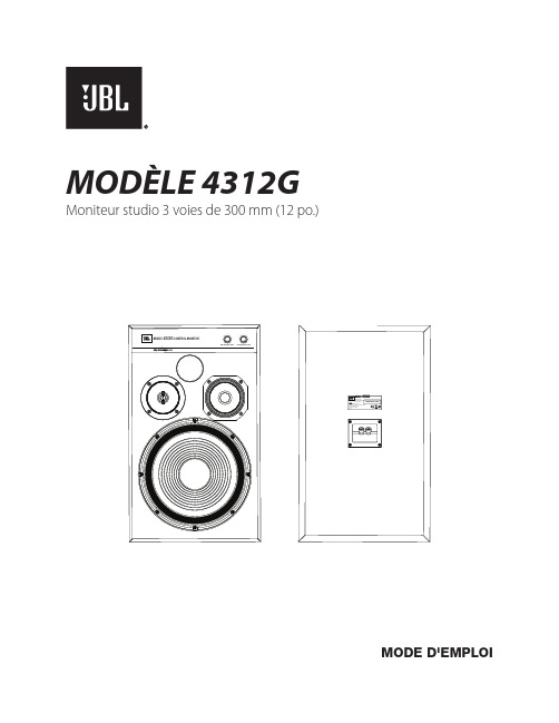
MODÈLE 4312G Moniteur studio 3 voies de 300 mm (12 po.)MODE D'EMPLOIINTRODUCTIONMerci d'avoir acheté le moniteur studio 3 voies JBL® 4312G.Depuis plus de 70 ans, JBL fournit des équipements audio aux salles de concert, aux studios d'enregistrement et auxcinémas du monde entier, la marque est devenue le choix de confiance des artistes de studio et des ingénieurs du sonles plus renommés. Le 4312G honore cet héritage avec la configuration 3 voies de 300 mm (12 po.) emblématique quidate de 1968 avec le moniteur de contrôle original modèle 4310. Offrant l'encombrement d'un moniteur compact, le4312G utilise des transducteurs JBL avancés tels que le haut-parleur grave JW300SW-8 à cône en pâte pure, le haut-parleur médium JM125PC-8 à cône en pâte pure enduite de polymère et le haut-parleur aigu 054ALMg-1 en alliagealuminium / magnésium.CONTENU DE LA BOÎTELes enceintes JBL 4312G sont vendues par paires appariées symétriques. Le carton extérieur permet de protéger deuxcartons internes contenant chacun une seule enceinte à grille amovible.EMPLACEMENT ET POSITIONNEMENTATTENTION : chaque 4312G pèse 25,2 kg (55,5 livres). Avant de placer l'enceinte sur une étagère ou une plate-forme, vérifiez que celle-ci est assez robuste pour supporter la masse du moniteur.Pour choisir l'emplacement de vos enceintes, étudiez votre pièce Array et pensez au positionnement en vous servant de l'illustration ci-dessous comme guide.Évitez de placer les enceintes près des amplificateurs de•puissance, des bouches de chauffage ou d'autres objets quiproduisent une chaleur importante.N e placez pas les enceintes dans des endroits très humides•ou poussiéreux.N e placez pas les enceintes sous la lumière directe du soleil•ou dans des endroits où elles seront exposées à une fortesource lumineuse.P our obtenir les meilleurs résultats, espacez les enceintes•de 1,8 - 2,4 m (6 - 8 pieds). Si vous écartez les enceintesdavantage, orientez-les vers la position d'écoute.L es enceintes produisent la scène stéréo la plus précise•quand l'angle formé par l'auditeur et les enceintes est de 40 à 60 degrés.P ositionnez chaque enceinte de telle façon que le haut-parleur aigu soit à peu près au niveau de l'oreille.•E n général, les graves sont amplifiés si l'enceinte est rapprochée d'un mur ou d'un coin. Pour obtenir les meilleures•performances, nous recommandons de placer les enceintes à au moins 50 cm (20 pouces) d'une paroi.L e 4312G peut être monté sur pied avec les pieds métalliques JBL optionnels (modèle JBL JS-120, vendu•séparément) qui orientent l'enceinte vers le haut.POSITIONS GAUCHES ET DROITESLe JBL 4312G est vendu sous la forme d'une paire d'enceintes symétriques dont l'une a le haut-parleur aigu à gaucheet l'autre a le haut-parleur aigu à droite, bien qu'aucune ne soit marquée ou définie comme une enceinte de canal« GAUCHE » ou « DROIT ». L'utilisation de l'une ou l'autre pour le canal gauche ou le canal droit dépendra d'unecombinaison de facteurs incluant la distance d'écoute des moniteurs, la largeur de la pièce, la réflectivité acoustique dela pièce et le placement horizontal ou vertical de l'enceinte.En général, il vaut mieux placer les enceintes en définissant un triangle équilatéral, représenté par la distance entre leshaut-parleurs aigus de chaque enceinte et par les distances entre l'auditeur et chaque haut-parleur aigu. Dans les piècesplus petites ou si la position d'écoute est relativement proche des enceintes, cela conduira habituellement à placer leshaut-parleurs aigus à l'intérieur du triangle d'écoute. Ce positionnement peut également être souhaitable dans unepièce aux réflexions acoustiques plus prononcées ou lorsque les enceintes sont placées sur une étagère ou près d'uneparoi.23Mode d’emploi du 4312G ORIENTATION HORIZONTALE :Canal gaucheCanal droitORIENTATION VERTICALE :Canal gauche Canal droitDans les pièces plus petites ou si la position d'écoute est relativement proche des enceintes, cela conduirahabituellement à placer les haut-parleurs aigus à l'intérieur du triangle d'écoute. Ce positionnement créera une scène sonore plus large, mais peut requérir un « resserrement » légèrement plus prononcé des enceintes des canaux gauches et droits afin de conserver une image centrale convenable. Ce positionnement peut également être souhaitabledans une pièce à l'absorption acoustique plus forte ou lorsque les enceintes sont placées sur la longueur d'une pièce rectangulaire.ORIENTATION HORIZONTALE :Canal gaucheCanal droitORIENTATION VERTICALE :Canal gauche Canal droit4BRANCHEMENTSATTENTION : veillez à ce que tous les appareils électriques du système soient éteints (et de préférence débranchés de leurs prises secteurs) avant de faire des branchements.Les enceintes et les amplificateurs ont des bornes de liaison positives et négatives (+ et –)correspondantes. Le 4312G a des bornes de raccordement codées en couleur. La borne« + » est rouge, et la borne « – » est noire. Reportez-vous à l'illustration à droite.Le 4312G est conçu de telle façon qu'une tension positive sur la borne « + » (rouge)produise un mouvement vers l'extérieur (vers la pièce) de ses haut-parleurs.Nous recommandons d'utiliser un câble d'enceinte de haute qualité avec codage dela polarité. Le côté du câble avec une bordure ou un autre codage est habituellementconsidéré comme la polarité positive (« + »).Pour que la polarité soit correcte, connectez chaque borne + au dos de l'amplificateur oudu récepteur à la borne + (rouge ) respective de chaque enceinte. Connectez les bornes« – » (noires ) de la même façon. Reportez-vous au mode d'emploi du récepteur ou del'amplificateur pour confirmer ses procédures de connexion.CONNEXION DE BASE À UN SEULCÂBLEBranchez l'amplificateur à chaque enceinte suivant lesindications de l'illustration à droite.IMPORTANT : n'inversez pas les polarités (c.-à-d., + sur – ou – sur +) pendant le branchement. Ceci produirait une image stéréo dégradée et réduirait les performances des graves.Les bornes plaquées or du 4312G peuvent accepterdivers connecteurs de fil : fil dénudé, connecteurs àcosses, connecteurs à fourche et fiches bananes.UTILISATION DE FILS DÉNUDÉS OU DE CONNECTEURS À BROCHE :IMPORTANT : veillez à ce que les fils ou broches (+) et (–)ne se touchent pas et ne touchent pas l'autre borne. Uncontact des fils peut créer un court-circuit et endommagervotre récepteur ou amplificateur.UTILISATION DES CONNECTEURS À COSSES :IMPORTANT : veillez à ce que les lames des connecteurs à fourche (+)et (–) ne se touchent pas et ne touchent pas l'autre borne. Un contactdes lames peut créer un court-circuit et endommager votre récepteurou amplificateur.UTILISATION DES FICHES BANANES :Récepteur ou amplificateur (un canal représenté)Panneau de connexion de l'enceintenégatives (–)positives (+)capuchon.ou le connecteur à broche dans la borne.pour bloquer le fil.A. D évissez le capuchon. B. I nsérez les lames du connecteur à fourche autour de la borne.C. S errez le capuchon.capuchon.trou du capuchon.COMMANDES / RÉGLAGESCommandes Atténuateurs des haut-parleurs MF et HFType de connecteur Bornes cinq voiesFinition Texture bois noire et grille noireDimensions (H x L x P)597 mm x 362 mm x 305 mm (23 1/2" x 14-1/4" x 12")Poids23,8 kg (52,4 lbs) chaque5Mode d’emploi du 4312GPlease visit / for additional language support on the user manual.Veuillez visiter / pour obtenir le mode d’emploi en d’autres langues.Para obter o manual do usuário em outros idiomas, acesse / Ga naar / voor de handleiding in andere talen.Gå til / for bruksanvisning på flere språk.Если вам требуется дополнительные версии руководства пользователя на других языках, посетите сайт / .別の言語に対応したユーザーマニュアルを読むには、JBL にアクセスしてください。
洛雷克安全摄像头说明书
Guide D'installationVersion Francaise1.0Caractéristiques de la Caméra2Caractéristiques de la Caméra• la technologie reflétante rend la caméra invisible à l'oeil humain et Permet pourtant à la caméra de correctement Visualiser• le Facteur en Forme de Miroir de Sécurité est Idéal pour lesApplications Commerciales/ détail • le Câble passant par le crochet de Montage Murale dissimule et protège le câble de Connexion• Montage au Plafond alignée oumontage au mur en utilisation le câble passant par le crochet inclut.Contenus de paquet1 x Caméra de Sécurité en couleur avec Miroir Dissimulée avec support montant1 x Clé d'Ajustage (Poursupport montant)Montage muralealignéeMontage muraleOptions de Montage3Options de MontageCette caméra peut être installé à un mur ou à un plafond, ou peut être monter avec alignement au plafond en utilisant le câble passant par le crochet.Montant au mur:1. Montez la caméra à la surface montante désirée en en fixant fermement le Support de fixation en utilisant 4 vis (aux points énumérés comme les Vis 1~4 sur le diagramme).2. Utilisez la clé d'ajustage pour régler l'angle désiré de la caméra (aux points A, B et à C sur le diagramme au dessous).3. Connectez le câble d'extension à la caméra.Options de Montage4Montant au plafond:1. Enlevez le Support de fixation du revers de la Caméra (4 vis)2. Percez un trou dans le plafond assez grand pour passer le Câble de BNC/Alimentation.NOTE : En utilisant la méthode de montant au plafond, passer le câble d'extension à l'endroit avant de monter la Caméra.3. Raccordez la fin de câble de BNC/alimentation de la caméra aux connexions BNC/alimentation sur le câble d'extension avant le fait d'installer la base de caméra.4. Vissez la base de caméra au plafond.5. Anglez la caméra en desserrant les vis de côté. Réglez l'angle désiré et serrez les vis.6. Il y a deux trous de vis sur la couverture de Dôme–Dès que les trous sont alliés, réglez l'Insertion du Dôme pour que l'ouverture soit alliés avec Lentille.pour s'assurer de mettre en ligne les trous de la Couverture du dôme avec les trous sur la base de la Caméra.7a. Vissez les deux vis de clip de côté sur lacouverture de dôme dans la base pour tenir lacouverture de dôme dans l'endroit.7b. Utilisez l'anneau de dôme de caoutchouc pour cacheter le dôme à la base.7a 7bOptions de Montage5Installation de la Caméra et le Câble d'Extension Optionnel1. Raccordez le câble d'extension optionnel à la Caméra:• Raccordez les fins BNC et l'alimentation du câble à la Caméra • Raccordez le connecteur d'Adaptateur d'alimentation au Câble d'alimentation de courant alternatif attaché à la caméra.Souvenez-vous de vérifier les fins du câble avant l'installation permanente, comme les fins deconnexion d'alimentation sont différentes (un côté a une connexion d'alimentation de barrique femelle et une fin a une prise d'alimentation d'électrique mâle.CAMÉRA : Raccordez les Câbles BNC et d'alimentation à la CaméraENTREE VIDÉO : Raccordez le câblede BNC à l'entrée de vidéo du moniteur et raccordez l'adaptateurDiagramme d'installation de la caméra2. Raccordez la fin de BNC du Câble d'Extension au DVR / le Système d'Observation ou à une TV/MAGNÉTOSCOPE.NOTE: Raccordez le BNC à l'Adaptateur RCA comme nécessaire pour assurer une connexion correcte.3. Raccordez l'Adaptateur d'alimentation A/C au Câble d'Extension (le connecteur Noir). Branchez l'adaptateur d'alimentation à une issue muraleSpécifications de la Caméra6Spécifications de la CaméraType de Détecteur d'Image Détecteur d'Image de CCD en couleur 1/3 pouce Format Vidéo NTSCPixels Efficaces510H x 492V (251K) Résolution Horizontale 420 Lignes de TVSystème de Scrutation 525 Lignes 2:1 Interlac Système Synchronisé IntérieurTau de S/N Plus de 52dB sans AGC IrisAESVitesse d'Obturateur d'AES 1/60 ~ 1/120,000Illumination Minimale 0.2 LUX (Sens-en-haut jusqu'à x32) Sortie Vidéo Composite 1.0Vp-p @ 75ohms Sortie d'audioNon SoutenuLentille / Longueur Focale F2.0 de 3.6 millimètres fixé FOV (Diagonale) 92°TerminaisonBNC, Jack d'Alimentation DC IR LED / Gamme de Vision NocturneN/AExigence d'alimentation12V DC ±10% Consommation d'alimentation 110mA or 1.4W Température d'opération14°F ~ 122°F / -10°C ~ 55°C。
ADAM Audio S6A Mk2 四通道活动主监控说明书
S6A Mk2 Operation manualEnglishIntroductionDear customer,Congratulations on choosing an ADAM Audio S6A Mk2 main monitor!ADAM loudspeakers are built for maximum quality reproduction and audioperfection. With the S6A Mk2 you have selected one of the most ambitiousspeaker systems available. This main monitor meets highest expectations insound quality and craftmansship.This manual is intended to provide you with information about your newADAM. It contains important information regarding safety, setting up,handling, and warranty. We request that you read these sections carefullyto ensure an easy set up and to prevent potential problems.The S6A Mk2 is suitable for main monitoring. It is perfectly suited for largecontrol rooms, post-production suites, etc.—an ideal tool for situations wherea combination of no-compromise sound reproduction and high SPL regionsis required.The S6A Mk2 is a four-way ported active system that uses a single ARTtweeter and two ART midrange drivers, ensuring full compatibility with thelatest expanded high frequency resolution media formats. It also employs two7“ HexaCone©-midwoofers and two 12“ HexaCone©-subwoofers. Driven by 6amplifiers with an overall power of 1000 watts (RMS), the S6A is powerfulenough for rooms of almost any size.If you have any questions about this or any of our products, please don’t hesi-tate to contact us–we will be happy to assist you in any possible way.For detailed information concerning the ADAM technologies and products,complete reviews, and a list of worldwide ADAM users and studios, pleasevisit our website:We hope very much that you really enjoy your new loudspeakers, and wishyou many delightful hours with them.The ADAM Audio Team2Table of contents1.Quick Start (4)1.1Important Information (4)1.2Quick Start S6A Mk2 (4)2.Speaker Placement (5)2.1General Recommendations (5)2.2Stereo Setup (5)2.3Surround Setup (5)3.Controls/Speaker Adjustement .....6-73.1The front (control) panel (6)3.2Input gain (6)3.3X-Curve Filter (6)3.4Driver gains (7)3.5High/low shelving (7)3.6Bass-EQ Section (7)3.7LED Dim (7)4.Troubleshooting (8)5.Maintenance (9)6.Transportation / Package (9)7.Environmental Information (9)8.EU Declaration of Conformity (10)9.Limited Warranty (11)9.1Terms and Conditions (11)9.2How to claim (11)10.Safety Instructions (12)11.Technical Data (13)341. Quick StartImportant information for set upAcclimation : After having unpacked your loudspeaker, please allow the sys-tem to acclimate to the temperature of the room. Please do not connect the speaker for approximately an hour.HQ Cabling : We recommend using high quality cables to guarantee optimal performance.Solid stand : It is important to ensure the speakers stand firmly on a solid ground (if they are not wall-mounted)!Package : We recommend not to damage the package and to retain it. The original packaging is the best guarantee for safe transportation (see 7.).Break-in time : Please note that the loudspeakers will need a few days to achieve optimum sonic performance.Quick start S6A Mk2Before connecting the loudspeakers to your audio components and the power source make sure that both the loudspeakers and your audio system is switched off!Set all level controls fully counterclockwise.Connect the loudspeakers with your audio units: Use a XLR cable. The male plug goes into the loudspeaker, the female plug into your audio component.Check if the specified voltage matches the voltage of the power supply you use. If this is not the case do not connect the loudspeakers to a power source! Please contact your local dealer or national distributor.If the voltages match, connect the loudspeaker via the included power cables to two AC sockets.Switch on your audio system. Switch on the main on/off switches on the front panel of the loudspeakers.Turn on your source of music and adjust the volume carefully.1.21.1d)a)b)c)e)5En gl is h2. Speaker PlacementGeneral recommendations/advisesDirect sound ways : There should be no obstacles in the way from the monitor to your ears. You should be able to see the speakers completely.Alignement : The loudspeakers should be aligned with the listener’s position.Nearby objects : Please note that vibrating parts of nearby objects can mask the sound.Tweeter at the height of ears : The tweeters should be positioned approxima-tely at the height of your ears. In case you need to position the speaker in a si-gnifi cant lower or higher position, the monitor should be angled accordingly.Stereo set upIf the loudspeaker is going to be used forstereo applications, the optimum listeningposition should be located in the middle of astereo triangle. This means that your listen-ing position will be located at the top of animaginary equilateral triangle and the twoloudspeakers should be placed at the othertwo points of this triangle.Surround set upSpeaker positioning for multi-channel stereo purposes is ideally based on a circle with speakers placed at 0° (Center), 30° (Front Right), 110° (Rear Right), 250° (Rear Left), 330° (Front Left), with the listener being the circle’s center (Radius between 0.7-2.0 m). This ITU recommended confi guration may vary depending on the purpose of the control room (music or fi lm). However, it is recommended to create a symmetrical listening position with the front side and surround speaker pointing to the listener’s ear.2.12.22.3Figure 1: Stereo TriangleFigure 2:Surround set up6The front (control) panelOn the front you will find a control panel that allows detailed fine-tuning of your monitors to your particular room acoustics and personal listening pref-erences. The following tips are intended to assist you at using the controls in the best manner.Please note that using the controls may have a great impact on the overall sound characteristics of your loudspeakers. We recommend using the con-trols with utmost care and only after several audio tests with familiar record-ings.Input gaincurve has to be applied. The X-curve engages a 3 dB per octave roll-off above 2 kHz. The S6A Mk2 and S7A Mk2 have a switch located below the input selector that activates this filter, eliminating the need for external processing during the film mix.Figure 3:Control panel3.13.23.37En g l i s halter in this band, from a certain point (6 kHz respectively 150 Hz in this case) the frequencies are gradually being changed (see figure 4 & 5).All LED indicators can be dimmed if necessary by pressing the ‘LED Dim’- button.Figure 4ROOM EQ >6 kHz for the high frequencies above 6 kHz Figure 5ROOM EQ <150 Hz for the lowfrequencies below 150 Hz3.53.484. TroubleshootingAll ADAM products are designed and manufactured to the highest quality standards. However, if any problems with your speaker occur, we recommend to proceed as follows:Problem : The LED shows normal operation (green) but there is either no oronly a distorted audio signal .If both (all) speakers are affected, the reason can probably be found within the signal path. If only one speaker is affected, the problem will probably be within this speaker.Check the wiringIs the cable defective? Are all cables connected correctly?Check the signal pathInterchange the cables of both loudspeakers. Does the problem change with one of the cables?Connect the monitor as directly to the signal source as possible (please mind the volume!). Is another part of the signal path (e.g. mixer, subwoofer) defec-tive?If the answer to all these question is ‘no’, the problem is being caused by the loudspeaker with the utmost probability.If the answer to at least one of these questions is ‘yes’, there will probably be another defective device within the signal path.Problem : You hear parasitic noises (like humming, buzzing, soughing, crack-ing).Please disconnect the signal cables.If the noises disappear, check the signal path.If the noises can still be heard, check for other electrical devices close to the speakers (mobile phones, switching power supplies, etc.). If there is no interfering device the speaker will probably cause the problem.4.14.2a)b)9En g l i s h 5. MaintenancePlease switch the loudspeaker off before cleaning!Please note that the diaphragms build up a magnetic field. Do not play with magnetic items at close range to the diaphragms.Please make sure that no liquids get inside the cabinet. Do not spray any fluids on the speaker. Do not use a wet cloth for cleaning.Do not use flammable or acidly chemicals for cleaning.Do not touch the membranes of the loudspeakers.We recommend using a lint-free, damp cloth for cleaning.The loudspeaker membranes may be dusted using a very soft brush.6. Transport / PackageIn case you have to send your speakers to any other location, it is of vital importance that you use the original packaging materials. Experience has shown that it is very difficult to avoid damage if you have to send them with-out these. ADAM Audio can not be held responsible for damages due to im-proper packaging.If a transport is necessary and the original package is no more available, a new one can be purchased from ADAM Audio.7. Environmental InformationAll ADAM products comply with international directives on the Restriction of Hazardous Substances (RoHS) in electrical / electronical equipment and the disposal of Waste Electrical / Electronic Equipment (WEEE).For disposal, please consult your local authorities for further information.108. EU Declaration of ConformityWe,ADAM Audio GmbHwhose registered office is situated atLobeckstr. 36, 10969 Berlin, Germanydeclare under our sole responsibility that the product:S6A Mk2complies with the EU Electro-Magnetic Compatibility (EMC) Directive 89/336/EEC, in pursuance of which the following standards have been ap-plied:EN 61000-6-1 : 2001EN 61000-6-3 : 2001EN 55020 : 2002EN 55013 : 2001and complies with the EU General Product Safety 2001/95/EC, in pursuance of which the following standard has been applied:EN 60065 : 2002.This declaration attests that the manufacturing process quality control and product documentation accord with the need to assure continued compli-ance.The attention of the user is drawn to any spezial measures regarding the use of this equipment that may be detailed in the owner’s manual.Signed:Roland StenzDirectorADAM Audio119. WarrantyADAM Audio GmbH provides a two year limited warranty for this product. If anything goes wrong with this product due to manufacturing defects, ADAM Audio and its national distributors will provide repair free of charge (exclu-sions may apply) and replacement parts.Terms and ConditionsThis guarantee complements any national/regional law obligations of deal-ers or national distributors and does not affect your statutory rights as a customer.This warranty is limited to the repair of the equipment.Neither transportation, nor any other costs, nor any risk for removal, trans-portation and installation of products is covered by this warranty.Products whose serial number have been altered, deleted, removed or made illegible are excluded from this warranty.The warranty will not be applicable in cases other than defects in materials and/or workmanship at the time of purchase and will not be applicable:for damages caused by incorrect installation, connection or packing,for damages caused by any use other than correct use described in the user manual,for damages caused by faulty or unsuitable ancillary equipment,if repairs or modifications have been executed by an unauthorized person,for damages caused by accidents, lightning, water, fire heat, public distur-bances or any other cause beyond the reasonable control of ADAM Audio.How to claim repairs under warrantyShould service be required, please follow the following procedure:If the equipment is being used in the country of purchase, you should contact your ADAM Audio dealer.If the equipment is being used outside the country of purchase, you should contact your ADAM Audio national distributor in the country of residence. You will be advised where the equipment can be serviced. Please visit our website to get the contact details of your local distributor.To validate your warranty, you will need a copy of your original sales invoice with the date of purchase.9.1d)a)b)c)e)9.21210. Safety InstructionsPlease read the following safety instructions before setting up your system. Keep the instructions for subsequent reference. Please heed the warnings and follow the instructions.Do not open the loudspeaker. There are no user-serviceable parts inside. In case of a problem, please contact either your ADAM dealer or us. We are happy to help. Always refer servicing to qualified personnel and never attempt to repair this product yourself.This product, as well as all attached extension cords, must be terminated with an earth ground three-conductor AC mains power cord like the one supplied with the product. To prevent shock hazard, all three components must always be used.Protect the cord from being walked on or pinched.Never replace any fuse with a value or type other than those specified. Never bypass any fuse.Always switch off your entire system before connecting or disconnecting any cables, or when cleaning any components.Please note that the diaphragms build up a magnetic field. Do not ply with magnetic items at close range to the diaphragms.Do not expose this product to rain or moisture, never wet the inside with any liquid and never pour or spill liquids directly onto this unit. Please do not ut any objects filled with liquids (e.g. vases, etc.) onto the speaker.Always use fully checked cables. Defective cables can harm your speakers. They are a common source for any kind of noise, hum, crackling etc.Always keep electrical equipment out of the reach of children.Always unplug sensitive electronic equipment during lightning storms.The monitor should be installed near the socket outlet and disconnection of the device should be easily accessible.To completely disconnect from AC mains, disonnect the power supply from the AC receptacle. Never use flammable or combustible chemicals for cleaning audio components. Avoid touching the speaker membranes and do not block the woofer’s ventilation ports. Never expose this product to extremely high or low temperatures. Never operate this product in an explosive atmosphere.High SPL’s may damage your hearing! Please do not get close to the loudspeakers when using them at high volumes.Assure free airflow behind the speakers to maintain sufficient cooling.13E n g l i sh 11. Technical DataADAM S6A Mk2 - active 4-ways bass reflex loudspeaker *1 = long term IEC 265-8-Wrms/10 min // *2 = nominal IEC 265-8 = Peak Power 5 µsec *3 = pay attention to the selected voltage on the rearside of the speakerADAM Audio GmbH Ederstr. 16 | 12059 Berlin-Germany phone: +49 30-863 00 97-0 fax: +49 30-863 00 97-7email:*******************ADAM Audio USA 31312 Via Colinas Unit 108 | Westlake Village | CA, 91362phone: +1 818-991 3800fax: +1-818-991 3808email:****************** S6A Mk2 ManualVersion 09.2008 English。
APPRO 高清两百万像素枪型网络摄像机 LC-7513 说明书

此款高画质网络摄影机系列,有着新颖设计的三串流影像压缩编码,提供同步化的H.264,M P E G 4 以为当前最受欢迎的影像压缩格式,高画质却有较小的档案大小,让录像时间有效延长,亦能让频宽相对变大,增加影像传输的速率。
H.264 视频压缩LC-7513高清两百万像素枪型网络摄像机清晰而宽广的监控视野 真实色彩 低热耗不当机产品特色客制化曝光排程–因应不同场景需求APPRO TECHNOLOGY INC. 欧普罗科技股份有限公司*所有规格日后若有变动不另行通知.产品规格表视频图像网络报警管理接口/ / H.264 LC-7513高清两百万像素日夜型枪型网络摄像机音频其它• : H.264 / MPEG4 / MJPEG.• : - :“4:3”: 1440x1080, 1280x960, 1024x768, 800x600, 640x480, 480x360, 320x240,160x120.“16:9”: 1920x1080, 1280x720, 800x450, 640x360, 480x270, 320x180, 176x120.• :- 同时提供 H.264, MPEG4, MJPEG.- 多组传输设定: 分辨率∕压缩格式∕画面更新 率∕品质.• 传输设定(Profiles): 3组.• 传输速率:- Single profile (1920x1080): 27FPS. - Multiple profile (1920x1080) : 20FPS .• :- 图像尺寸, 品质及传输速率/日夜模式/ 翻转及镜像/ 曝光控制/自动白平衡, 明亮度, 饱和度, 对比,锐利度/ 时间及文字标示/隐私遮挡区域.• 曝光模式:室内, 室外, 夜间, 低噪, 移动, 客制化1~3, 排程.• 视频管理软件: SDK, 包含 HTTP- API / ActiveX / ONVIF.视频流压缩分辨率视频比率视频串流视频视频视频视频视频调节功能调节• 安全性: 多级密码保护,IP 地址过滤,HTTPS加密, 使用者纪录.• 通讯协议: IPv4, HTTPS, HTTP, TCP, UDP, RTP/RTCP/ RTSP, DHCP, NTP, FTP, SMTP, UPnP, ICMP, ARP, DDNS, PPPoE, SAMBA.• 使用者: 允许同时10位使用者.• 韧体更新: SD 卡 / HTTP.• 录像: SD 卡, SAMBA, FTP.• 事前报警.• 移动侦测: (512 个独立区域 & .• 功能: 位移侦测、排程、警报输入、网络断线、网络 ∕远程数字警报输入.• 通知功能: SD 卡 录像, SMTP, FTP, HTTP, 报警输出接口.灵敏度触发: 0~100 %)• RJ-45: 10BASE-T/100BASE-TX.• 数字输入/输出: 承插式: 1 x 警报输入 / 1 x 警报输出 / 1 x 电源输出(DC 12V) / 1 x 接地线 / 2 x RS-485. • 耳机插孔 : 2 x 3.5 mm(1 x Audio in [mic. in / line in], 1 x Audio out[line output]).• DIP 功能切换: 1. AES / 2. DC iris / 3. DHCP / 4.Static IP. • 光圈: DC IRIS.• Reset: 回复原厂设定值.• 本机储存: SD / SDHC 卡插槽.• LED 灯号: 电源 / 网络 / SD 卡.• 电源:- DC 12V (DC power jack).- AC 24V (2pin terminal block).- 802.3af compliant Power over Ethernet (IEEE 802.3af ,Class 2).• 消耗功率: ≦6瓦.• 中央处理机: TMS320DM368.• OS: Linux 2.6 kernel.• 工作温度: 0℃ ~ 50℃(32℉ ~ 122℉).• 安规认证: CE, FCC, RoHS,C-Tick.• 尺寸 (HxWxD): 56 x 68 x 125 mm.• 附件:- 快速安装手册.- 光盘 x 1 ( 含使用说明书 ).- 电源适配器: (输入: AC 100-240V, 50/60Hz, 输出: DC 12V, 1A). - USB 连接线 x 1.• 音讯串流: 双向.• 压缩格式: G.711u / G.726.• 声音传输速率: G.711u 64kbps / G.726 32kbps.• 输入 / 输出: 1 x 输入 / 1 x 输出(3.5mm 耳机插孔).• 摄像传感器: 1/2.7” Omni Vision 2M 感应器.• 镜头: CS-mount• 最低照度: 彩色: 0.2 Lux @ F1.2.; 黑白: 0.01Lux@F1.2.• 机械红外截止滤光片.• 日夜模式: 自动∕日∕夜∕排程.上海市长宁区遵义路 107 号安泰大楼 408 室联络人: 钟敏原(Jemmie Chung)QQ: 1524734168 / SKYPE: jemmiechung 手机: 152********/ 136******** 电话: 021-******** 传真: 021-********E-mail:jemmiechung @台湾新北市新庄区中正路66号13F 电话: +886-2-8992-1177 传真: +886-2-8992-0077E-mail:jemmiechung @ Web: 。
卡托尼(Cartoni)Focus 12流动头用户手册说明书

PROFESSIONAL CAMERA SUPPORT USER’S MANUAL & MaintenanceI ndex1.S afety & S et-U p I ntrodUctIon52.o peratIng elementS63.p rocedUreS84.S pecIfIcatIonS95.m aIntenance106.W arranty107.a cceSSorIeS & prodUct lIne11CARTONI®All rights reserved ©Manual Version: 2.3Issue date: March 20204The FOCUS 12 Fluid Head is the ideal support for the latest smaller, lighter high-performance Cameras weighing from 0 to 12 kg (0 to 26.4 lbs). Extremely compact and lightweight, the innovative FOCUS 12 features a continuously variable fluid damping system on both pan and tilt move-ments and an unrivaled patented variable counterbalance which brings its range of use to cover all existing ENG and lighter high-performance Cam-eras.The FOCUS 12 Head comes equipped with a sliding quick release Eu-ropean Camera plate plate, illuminated spirit level and telescopic pan bar. Its tilting range is +/- 90° has a perfect response throughout the entire tilt range. This head interfaces with all 100 mm bowl base Tripods and sup-ports.The extreme ruggedness and versatility together with a superior quality/price ratio makes the FOCUS 12 the best possible support for independentcontent creators, news Operators and Videographers.Before using the product read this user manual.Before installing the Fluid Head on the Tripod check the Tripod sta-bility.Verify that the Camera payload (including lens and all accessories) is lower than the maximum capacity of the Fluid Head.Before setting up the Camera make sure that the Fluid Head is in goodconditions and bares no evident damages.1 Camera plate2 Sliding camera platform3 Pan bar attachment4 Pan bar extension5 Pan drag selector6 Pan brake lever7 Tilt brake lever ❸❺❹❼❻2. o peratIng e lementS8 Camera plate release lever9 Safety button10 Sliding platform lock11 Tilt drag selector12 Illuminated spirit level13 Counterbalance selector14 Tie down knob15 Pan bar⓬⓮⓫⓭Place the FOCUS 12 on your Tripod by loosening the tie-down knob (14) under the Fluid Head and level using the level bubble (12). In low light conditions, press button (12) for light.Connect the Pan bar (15) to the Fluid Head tightening the lever (3) on the Pan bar attachment and select your desired operating angle. The telescopic Pan bar length can be adjusted via lever (4).Lock both Pan and Tilt brakes (6 & 7), turn both Tilt drag selector (11) and counterbalance knob (13) to the minimum.Open the Camera plate lock lever (8) completely to release the Cam-era plate (1).Remove the Camera plate (1) from the sliding Camera platform (2) by squeezing simultaneously Camera plate lever (8) and the safety but-ton (9). Attach the Camera plate (1) to the bottom of the Camera and tighten the clamping screw to secure the Camera. Try to center the Camera plate on the Camera, keeping the center of gravity position in mind.Lock the sliding platform lever (10), click the Camera into the quick release sliding platform (2), the plate will lock into place.Hold the Camera in horizontal position with the Pan bar (15) and re -lease the Tilt brake lever (7). Release the sliding platform lever (10) and find the correct center of gravity position, by sliding the Camera plat -form (2) back and forth until you have achieved the correct balance. Lock the sliding platform lock (10).3. p rocedUreSSet the counterbalance system by turning the balance knob clockwise (13) to appropriate tension. The Camera has to stay at any tilt angle. Eventually fine-tune by adjusting the sliding plate.Unlock the Pan brake lever (6) and set the Fluid drag control by adjust-ing selectors (5 & 11).When spirit bubble light fails it is time to replace the batteries (12). Pull out the battery tray.Minimum payload 0 Kg 0 lbsMaximum payload 12 Kg 26.4 lbsWeight 2,5 Kg 5.5 lbsBowl diameter 100 mmFluid control ContinuousCounterbalance ContinuousPan range 360°Tilt range +/- 90°T emperature range -40 / +60 °C -40 / +140 °F 4. S pecIfIcatIonS5. m aIntenance6. W arrantyWith indoor use - when needed - just clean the FOCUS 12 and Tripod with a soft cloth. Dirt accumulated during storage may be removed using a brush or Air spray.CARTONI products main mechanisms are sealed as they are also built for professional outdoor use.However, use under rough conditions will require special care. Salt water is very corrosive and can cause extreme damages. In atempt to avoid fur-ther damage the Fluid Head should be washed off with fresh water at the earliest opportunity and dried before storage.Sand and dirt are abrasive and should be removed using a semi-stiff brush or Air spray.Disconnect the spirit level battery during long term storage.All CARTONI Fluid Heads & Pedestals have a free of charge three (3) year warranty. Register your product at within 30 days from date of first purchase/invoice to receive further two (2) year warranty for the unsurpassed free five (5) year warranty.Tripods, spreaders, dollies and all accessories are guaranteed one (1) year from the date of first purchase/invoice.CARTONI warrant that the product supplied will - under proper use - be free from defects in workmanship and materials and agrees that it will, at its option, either repair or replace any defective part within duration of warranty from date of first purchase with no labour charge.This warranty does not apply to any CARTONI product that has been damaged in shipping or handling, abused, misused, operated contrary to instructions for use, neglected, normal wear or tear, modified or changed in design or construction or serviced by unauthorized parties.Repairs or misuse by any unauthorized parties will void this warranty. Warranty claims must be submitted – in writing - to the factory for veri- fication or to an authorized distributor/dealer designated by CARTONI . It is the end user’s responsibility when ordering to ensure that the prod-ucts ordered conform to his requirements.All freight of product to CARTONI must be prepaid. All implied war-ranties are limited to the time period set forth herein & subject to change without notice.No liability can be accepted for any variation.For the complete Accessories list & Product line please visit CARTONI ’s official website .Every product has an updated list of compatible items sorted by groups, with descriptions and technical data.7. a cceSSorIeS & prodUct lIneCARTONI S.p.A Via di Portonaccio, 33/B - 00159 Rome (Italy)Phone +39 06 4382002Fax +39 06 43588293Email:*******************PROFESSIONAL CAMERA SUPPORT。
LBV2531 序列 夜视安防摄像头 快速使用指南说明书
Ressources Besoin d’aide?
Visitez notre site Web pour les mises à jour du logiciel et les manuels d’instructions complets
Avertissement/Mise en garde
• Lire attentivement ce guide et le garder pour consultation ultérieure
4
Cliquez sur l’onglet Downloads
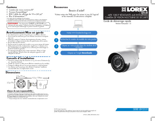
MPX 1080 P RÉSISTANTE AUX INTEMPÉRIES CAMÉRA DE VISION NOCTURNE DE SÉCURITÉ
Guide de démarrage rapide
Version française 1.0
Conseils d’installation
• Pointer les caméras dans des directions où il y a le moins d’obstruction (p. ex. : branches d’arbres).
• Installer les caméras où elles seront difficiles à atteindre par les vandales.
• Ne pas démonter les caméras.
• Ne pas pointer la caméra vers le soleil ou une source intense de lumière.
• Utiliser seulement le bloc d’alimentation régulé fourni. L’utilisation d’un bloc d’alimentation non stabilisé et non conforme peut endommager ce produit et annuler la garantie.
E.TRADIO 高保真监听头 说明书

E.TRADIO 高 保 真 监 听 头用户手册前言..............................................................2 成套监听头及配件..................................................4 安全注意事项......................................................4 一般连接..........................................................5 性能指标..........................................................11 频响及指向曲线图..................................................12 附录:声学常识. (13)前 言感谢阁下的信任购买E.TRADIO监听头。
本手册对此监听头作了详细介绍,为了能长期正确使用,并充分利用它的所有功能,建议您在使用前认真阅读此用户手册。
E.TRADIO监听头产品是我公司OEM生产的以色列TRADIO系列监听之一,外形简洁美观,投放市场以来受到广大客户的好评。
该监听头采用经过严格挑选的镀银震膜电容咪头,具有很好的全指向特性,可根据不同场合需要选择使用。
供电范围宽,可采用8-20V直流稳压电源供电,便于使用。
该监听头性能好、经久耐用、频响效果好、音色圆润、音调柔和。
放大器部分采用了低噪声前置放大器,性能稳定,失真小,噪声低。
其配置齐全,使用方便,而特别适合于银行大厅、看守所、审讯室、监仓、上访接待处、招标会议室等场所的录音。
以色列E.TRADIO专业环境声音(有线)监听探头,国内OEM生产。
高保真、语音清晰、噪音低。
镀银震膜电容咪头,本底噪声小、采音更广泛。
自适应动态降噪处理,内置高速DSP数字信号处理器。
V3监控部分操作手册
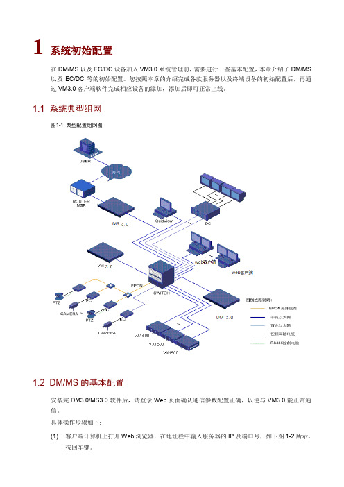
1 系统初始配置在DM/MS以及EC/DC设备加入VM3.0系统管理前,需要进行一些基本配置,本章介绍了DM/MS 以及EC/DC等的初始配置。
您按照本章的介绍完成各款服务器以及终端设备的初始配置后,再通过VM3.0客户端软件完成相应设备的添加,添加后即可正常上线。
1.1 系统典型组网图1-1典型配置组网图1.2 DM/MS的基本配置安装完DM3.0/MS3.0软件后,请登录Web页面确认通信参数配置正确,以便与VM3.0能正常通信。
具体操作步骤如下:(1) 客户端计算机上打开Web浏览器,在地址栏中输入服务器的IP及端口号,如下图1-2所示,(2) 在登录对话框中输入管理员密码admin,点击<登录>按钮,即可进入Web页面。
登录系统后,进入[系统配置/通信参数配置]页面,确认服务器IP地址(VM3.0/ISC3000-E的IP地址)是否正确,其他参数保持默认值即可。
其他相关内容可参见联机帮助。
登录DM和MS需要使用IP+端口方式:●登录DM,需要在浏览器地址栏中输入DM IP:8080●登录MS,需要在浏览器地址栏中输入MS IP:8081图1-2登录服务器1.3 VX500的基本配置通过登录Web页面确认通信参数配置正确,以便与VM3.0能正常通信。
具体操作步骤如下:(1) 客户端计算机上打开Web浏览器,在地址栏中输入服务器的IP,按回车键。
(2) 在登录对话框中输入管理员密码admin,点击<登录>按钮,即可进入Web页面。
登录系统后,进入[系统配置/通信参数配置]页面,检查服务器IP地址是否正确即可,其他参数保持默认值即可。
配置VX500的阵列需要在VM3.0客户端上进行,具体操作请参见“添加VX500”。
图1-3登录VX5001.4 VX1500基本配置登录Web页面,完成VX1500的基本配置后,即可与VM3.0能正常通信。
VX1500出厂管理口(100M网口)默认IP地址为192.168.0.1。
洛雷克安全摄像头系列产品说明书
Information sur le produit
Notices techniques
Guides d'utilisation
Mises à niveau des logiciels
Guides de démarrage rapide
Mises à jour du micrologiciel
Copyright © 2014 Lorex Corporation
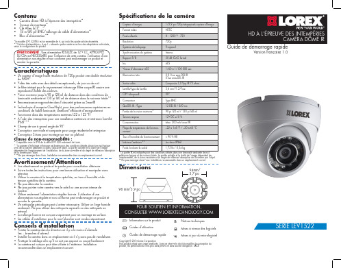
HD À L'ÉPREUVE DES INTEMPÉRIES CAMÉRA DÔME IR
Guide de démarrage rapide
• Technologie d'imagerie ClearNight, pour des performances supérieures en conditions de faible luminosité, améliore l'efficacité d'enregistrement
• Fonctionne dans des températures extrêmes (-22 à 122 °F)
Avertissement/Attention
• Lire attentivement ce guide et le garder pour consultation ultérieure • Suivre toutes les instructions pour une bonne utilisation et manipuler avec
720p Progressif
AVERTISSEMENT - Une alimentation RÉGULÉE de 12 V CC, APPROUVÉE UL/CSA est NÉCESSAIRE pour l'utilisation de cette caméra. L'utilisation d'une alimentation non-régulée et non conforme peut endommager ce produit et annuler la garantie.
TRADIO拾音器用户手册

第2页
拾音器用户手册
第四章 拾音器及拾音器接线
快鱼TRADIO品牌拾音器目前共有24个系列多款拾音器,其中分基本型和定制型。 产品参数及图例请见快鱼官方网站和宣传资料。
TRADIO拾音器接线方式分两种,大多数款型是外接3芯线,少部分为三芯接线端 子。如下图所示:
红线(V) DC12V电源正极; 黑线(G) 电源负极和音频地; 黄线(A) 音频线;
拾音器灵敏度高,同一个房间扩音/放音容易引起声音自激及啸叫
4. 严禁室外使用户内型拾音器
TRADIO户内型拾音器的咪头和电路没有做防水处理,容易损坏。 2012年11月
用户手册
版权声明
本手册为北京快鱼科技有限公司版权所有。在未经书面许可的前提下不得以任何形 式或方法复印、传播、转录、存档或翻译成其他语言及电脑语言。公司品牌和产品名 称TRADIO® 为商标或注册商标。本公司不对本文的内容作转述和承诺,特别不对商 品作暗示性承诺。本公司保留修改本手册的权利,无须提前通知其他方而变更本文。 在未经本公司许可的前提下,不得部分或全部复制本手册。
修改承诺
本手册的修改无需预先通知。厂商不对本文的内容作转述和承诺,特别不对商品 做暗示性承诺。本公司保留修改本指南的权利,且无须提前通知其他方而随时变更本 文。
法律承担责任
TRADIO® 系列拾音器(或称监听头)专为安防系统音视频监控配套设备所。 TRADIO® 电声产品仅供单位安防工程使 用,请个人用户勿扰。本公司不对用户使用本产品而引起的经济及法律纠纷承担任何 责任。
第5页
拾音器用户手册
然后从电源适配器到设备用其他线缆: 1、使用两端带BNC接口的视频电缆连接到DVR、音视频矩阵、音视频采集卡等其他 设备;
纽扣摄像头使用说明书(3篇)

第1篇一、产品简介纽扣摄像头,顾名思义,是一种体积小巧、隐蔽性强的摄像头。
它广泛应用于家庭、办公、户外等多种场合,可用于实时监控、远程监控、安全防范等。
本说明书将详细介绍纽扣摄像头的使用方法、注意事项及常见问题解答。
二、产品规格1. 尺寸:约15mm×15mm×5mm2. 传感器:高清CMOS传感器3. 分辨率:1920×1080(1080P)4. 视场角:约120°5. 夜视距离:约10米6. 存储方式:TF卡(最高支持32GB)7. 工作电压:3.7V8. 工作电流:≤100mA9. 工作温度:-20℃~60℃10. 存储温度:-40℃~70℃三、使用方法1. 开机准备(1)将纽扣摄像头充电至充满(充电时间约2小时)。
(2)插入TF卡(请确保TF卡格式化为FAT32格式)。
(3)连接电源,按下电源键,摄像头进入待机状态。
2. 连接手机(1)在手机上下载并安装纽扣摄像头配套的APP。
(2)打开APP,按照提示完成注册和绑定操作。
(3)在APP中选择“添加设备”,扫描摄像头背面的二维码,完成绑定。
3. 视频监控(1)在APP中选择已绑定的摄像头,进入实时预览界面。
(2)调整摄像头角度,确保监控区域符合需求。
(3)如需录像,点击“录像”按钮,可进行本地录像或云端存储。
4. 其他功能(1)设置:在APP中可设置摄像头参数,如分辨率、录像时长、报警设置等。
(2)移动侦测:开启移动侦测功能,摄像头可自动识别异常移动,并及时发送报警信息。
(3)定时任务:设置定时任务,摄像头可定时录像,方便查看历史录像。
四、注意事项1. 确保摄像头安装位置隐蔽,避免被他人发现。
2. 请勿将摄像头安装在强光、高温、潮湿等恶劣环境下。
3. TF卡存储空间不足时,请及时更换或格式化TF卡。
4. 使用过程中,请勿频繁开关机,以免影响摄像头寿命。
5. 请勿使用非原装充电器为摄像头充电,以免造成安全事故。
FLIR DNR300系列QCG前端网络摄像头系统用户指南说明书

Les informations contenues dans ce document sont indiquées CD(logiciel et guide de l'utilisateur inclus)Guides de démarragerapideAdaptateur d'alimentation (x 2)Câble EthernetSouris USBEnregistreur de vidéosurveillance en réseauSérie DNR300Guide de connexion rapideBrancher les caméras à un Routeur* /proPour obtenir du soutien, visitez l'adresseLes plus récents logiciels et guides de l'utilisateur sont disponibles à l'adresse :/proCliquez deux fois un canal pour le visualiser en Cliquez pour ouvrir une option de menu.Utilisation de la sourisRéglage de la date et de l'heure123Enregistreur de vidéosurveillance en réseauSérie DNR300Guide de connexion rapide3. Cliquez sur Recherche IP .4. Cliquez sur OK .À l'aide des menus déroulants, sélectionnez les canaux que vous souhaitez lire. Cliquez sur les options d'affichage () pour lire plusieurs canaux en même temps. Cliquez à l'intérieur de la Cliquez à l'intérieur de la barre pour choisir l'heure de lecture.4. Sélectionnez la caméra, ou les caméras, que vous souhaitez ajouter et cliquez sur Ajouter .Si l'indicateur d'état est rouge, cliquez sur . Au besoin, mettez à jour les renseignements suivants.Mot de passe : Entrez le mot de passe de la caméra.Utilisateur : Entrez le nom d'utilisateur de la caméra.Fabricant : Choisissez le fabricant de votre caméra IP .Port HTTP : Entrez le port HTTP de la caméra. Port RTSP : Entrez le port HTTP de la caméra.Cliquez sur OK . Cliquez sur OK de nouveau pour sauvegarder les changements.REMARQUE : Consultez le guide de l'utilisateur fournit sur le CD pour obtenir plus d'information concernant laREMARQUE : Consultez le guide de l'utilisateur pour obtenir plus d'information sur le nom d'utilisateur et le mot de passe par défaut ou les ports utilisés.5. Si l'indicateur d'état est vert, la caméra est connectée et aucune configuration supplémentaire n'est requise. Cliquez sur OK pour sauvegarder les changements.。
D0T Series 音频弹头摄像头用户手册说明书

D0T Series Audio Bullet CameraUser ManualUser ManualThank you for purchasing our product. If there are any questions, or requests, do not hesitate to contact the dealer.This manual applies to the models below:This manual may contain several technical mistakes or printing errors, and the content is subject to change without notice. The updates will be added to the new version of this manual. We will readily improve orupdate the products or procedures described in the manual.01000020210421Regulatory InformationFCC InformationPlease take attention that changes or modification not expressly approved by the party responsible for compliance could void the user’s authority to operate the equipment.FCC compliance: This equipment has been tested and found to comply with the limits for a Class A digital device, pursuant to part 15 of the FCC Rules. These limits are designed to provide reasonable protection against harmful interference when the equipment is operated in a commercial environment. This equipment generates, uses, and can radiate radio frequency energy and, if not installed and used in accordance with the instruction manual, may cause harmful interference to radio communications. Operation of this equipment in a residential area is likely to cause harmful interference in which case the user will be required to correct the interference at his own expense.FCC ConditionsThis device complies with part 15 of the FCC Rules. Operation is subject to the following two conditions:1. This device may not cause harmful interference.2. This device must accept any interference received, including interference that may cause undesired operation.EU Conformity StatementThis product and - if applicable - thesupplied accessories too are marked with"CE" and comply therefore with theapplicable harmonized European standards listed under the Low Voltage Directive2014/35/EU, the EMC Directive 2014/30/EU, the RoHS Directive 2011/65/EU.2012/19/EU (WEEE directive): Productsmarked with this symbol cannot bedisposed of as unsorted municipal waste inthe European Union. For proper recycling,return this product to your local supplierupon the purchase of equivalent new equipment, or dispose of it at designated collection points. For more information see: . 2006/66/EC (battery directive): This product contains abattery that cannot be disposed of asunsorted municipal waste in the EuropeanUnion. See the product documentation forspecific battery information. The battery ismarked with this symbol, which may include lettering to indicate cadmium (Cd), lead (Pb), or mercury (Hg). For proper recycling, return the batteryto your supplier or to a designated collection point. For more information, see: .Industry Canada ICES-003 ComplianceThis device meets the CAN ICES-3 (A)/NMB-3(A) standards requirements.WarningThis is a class A product. In a domestic environment this product may cause radio interference in which case the user may be required to take adequate measures.Safety InstructionThese instructions are intended to ensure that user can use the product correctly to avoid danger or property loss.The precaution measure is divided into “Warnings” and “Cautions”.Warnings: Serious injury or death may occur if any of the warnings are neglected.Cautions: Injury or equipment damage may occur if any of the cautions are neglected.Warnings● In the use of the device, you must be in strictcompliance with the electrical safety regulations of the nation and region.● Input voltage should meet both the SELV (Safety Extra Low Voltage) and the Limited Power Source with 12 VDC according to the IEC60950-1 standard. Refer to technical specifications for detailed information. ● Do not connect multiple devices to one poweradapter to avoid over -heating or a fire hazard caused by overload.● Make sure that the plug is firmly connected to the power socket.● Make sure that the device is firmly fixed if wall mounting or ceiling mounting is adopted.● If smoke, odor or noise rise from the device, turn off the power at once and unplug the power cord, and then contact the service center.● Never attempt to disassemble the camera by unprofessional personal.Cautions● Do not drop the camera or subject it to physical shock.● Do not touch senor modules with fingers.● Do not place the camera in extremely hot, cold (theoperating temperature shall be -40°C to 60°C), dusty or damp locations, and do not expose it to high electromagnetic radiation.● If cleaning is necessary, use clean cloth with a bit of ethanol and wipe it gently.● Do not aim the camera at the sun or extra bright places.● The sensor may be burned out by a laser beam, so when any laser equipment is in using, make sure that the surface of sensor will not be exposed to the laser beam.● Do not expose the device to high electromagnetic radiation or extremely hot, cold, dusty or damp environment.● To avoid heat accumulation, good ventilation is required for the operating environment.● Keep the camera away from liquid while in use for non -water -proof device.● While in delivery, the camera shall be packed in itsoriginal packing, or packing of the same texture.Mark Description1 Introduction1.1 Product FeaturesThe main features are as follows: ● High performance CMOS sensor ● Smart IR● Audio over coaxial cable ● Built -in mic● 4 in 1 video output1.2 Overview1.2.1 Overview of Type I CameraFigure 1-1 Overview of Type I Camera1.2.2 Overview of Type II CameraNote:Press and hold the switch button for 5 seconds to switch the video output. Four kinds of video outputs are available: TVI, AHD, CVI, and CVBS.2 InstallationBefore you start● Make sure that the device in the package is in good condition and all the assembly parts are included. ● Make sure that all the related equipment is power -off during the installation.● Check the specification of the products for the installation environment.● Check whether the power supply is matched with your power output to avoid the damage.● Make sure the wall is strong enough to withstand three times the weight of the camera, and the mount.● If the wall is cement, insert expansion bolts before installing the camera. If the wall is wooden, use self -tapping screws to secure the camera.If the product does not function properly, contact your dealer or the nearest service center. DO NOT disassemble the camera for repair or maintenance by yourself.2.1Installation of the CameraBefore you start:The installation of type I and type II camera are similar. Following pictures are only for reference. Take the actual object as standard.2.1.1Ceiling/Wall Mounting without Junction Box Before you start:The installation of ceiling mounting and wall mounting are similar. Following takes ceiling mounting as an example.Steps:1.Drill the screw holes and the cable hole (optional)on the ceiling.2.Route the cables through the cable hole, or the sideopening.3.Attach the bracket to the ceiling, and secure thecamera with supplied screws. For cement ceiling,you need to install the expansion bolts at first.Figure 2-1Attach the Camera to the Ceiling Note:The supplied screw package contains self-tappingscrews, and expansion bolts.4.Connect the corresponding power cord, and videocable.5.Power on the camera to check whether the imageon the monitor is gotten from the optimum angle. If not, loosen the trim ring to adjust the position.[0° to 360°]]to 180°]TRFigure 2-23-Axis Adjustment1).Loosen the T adjusting screw to adjust the tiltposition [0° to 180°].2).Loosen the trim ring to adjust the pan position[0° to 360°].3).Loosen the R adjusting screw to adjust therotation position [0° to 360°].6.Tighten screws and the trim ring to finish theinstallation.2.1.2Ceiling/Wall Mounting with Junction Box Before you start:You need to purchase a junction box in advance. Steps:1.Paste the drill template on the ceiling/wall.2.Drill screw holes and the cable hole on the ceilingaccording to the drill template.3.Take apart the junction box, and align the screwholes of the camera with those on the Junctionbox’s cover.4.Attach the camera on the junction box’s cover withsupplied screws.Figure 2-3Attach the Camera on the Junction B ox’sCover5.Secure the junction box’s body on the ceiling/wallwith supplied screws.Junction BoxBodyFigure 2-4Secure the Junction Box on the Wall/Ceiling 6.Route the cables through the bottom cable hole, orthe side cable hole of the junction box.bine the junction box cover with its body.Figure 2-5Combine the Junction Box Cover back to itsBody8.Repeat the step 4 to 6 of 2.1.1Ceiling/WallMounting without Junction Box to finish theinstallation.3Menu DescriptionPlease follow the steps below to call the menu. Note:The actual display may vary with your camera model. The menu is not available when you switch the video output to CVBS.Steps:1.Connect the camera with the TVI DVR, and themonitor, shown as the figure 3-1.Figure 3-1 Connection2. Power on the camera, TVI DVR, and the monitor to view the image on the monitor.3. Click PTZ Control to enter the PTZ Control interface.4. Call the camera menu by clicking button, or call the preset No. 95.Figure 3-2 Main Menu Overview5. Click the direction arrow to control the camera.1). Click up/down direction button to select the item.2). Click Iris + to confirm the selection.3). Click left/right direction button to adjust the value of the selected item.3.1 VIDEO FORMATYou can set the video format to 2MP@30fps or 2MP@25fps .3.2EXPOSUREEXPOSURE MODEYou can set the EXPOSURE MODE to GLOBAL, BLC, HLC, or DWDR.●GLOBALGLOBAL refers to the normal exposure mode which adjusts lighting distribution, variations, andnon-standard processing.●BLC (Backlight Compensation)BLC (Backlight Compensation) compensates light to the object in the front to make it clear, but this may cause the over-exposure of the background where the light is strong.●HLC (Highlight Compensation)HLC stands for highlight compensation. The camera detects the strong spots (the over-exposure portion of image), then reduce the brightness of the strong spots to improve the overall images.●DWDR (Digital Wide Dynamic Range)Digital wide dynamic range gives the camera the ability to view dark areas of the given image as well as extremely lighted portions of the image, or areas of high contrast.AGC (Auto Gain Control)It optimizes the clarity of the image in poor light conditions. The AGC level can be set to HIGH, MEDIUM, or LOW.Note:The noise will be amplified when setting the AGC level.3.3DAY/NIGHTCOLOR, B&W (Black and White), and AUTO are selectable for DAY/NIGHT switch.COLORThe image is colorful in day mode all the time.B&W (Black and White)The image is black and white all the time, and the IR LIGHT turns on in the poor light conditions.You can turn on/off the IR LIGHT and set the value of SMART IR in this menuFigure 3-3DAY/NIGHT●IR LIGHTYou can turn on/off the IR LIGHT to meet the requirements of different circumstances.●SMART IRThe Smart IR function is used to adjust the light to its most suitable intensity, and prevent the image from over exposure.AUTOAutomatically switch Color, or B&W (Black and White) according to actual scene brightness.You can turn on/off the IR LIGHT, and set the value of SMART IR in this menu.Figure 3-4DAY/NIGHT●IR LIGHTYou can turn on/off the IR LIGHT to meet the requirements of different circumstances.●SMART IRThe Smart IR function is used to adjust the light to its most suitable intensity, and prevent the image from over exposure.●D→ N Threshold (Day to Night Threshold)Day to Night Threshold is used to control the sensitivity of switching the day mode to the night mode. You can set the value from 1 to 9. The larger the value is, the more sensitive the camera is.●N→ D Threshold (Night to Day Threshold)Night to Day Threshold is used to control the sensitivity of switching the night mode to the day mode. You can set the value from 1 to 9. The larger the value is, the more sensitive the camera is.3.4VIDEO SETTINGSMove the cursor to VIDEO SETTINGS and click Iris+ to enter the submenu. IMAGE MODE, WHITE BALANCE, BRIGHTNESS, CONTRAST, SHARPNESS, SATURATION, DNR, and MIRROR are adjustable.Figure 3-5VIDEO SETTINGSIMAGE MODEIMAGE MODE is used to adjust the image saturation, and you can set it to STD (Standard) or HIGH-SAT (High Saturation).WHITE BALANCEWhite balance, the white rendition function of the camera, is to adjust the color temperature according to the environment. It can remove unrealistic color casts in the image. You can set WHITE BALANCE mode to AUTO, or MANUAL.●AUTOUnder AUTO mode, white balance is being adjusted automatically according to the color temperature of the scene illumination.MANUALYou can set the R-GAIN/B-GAIN value to adjust the shades of red/blue color of the image.Figure 3-6MWB MODE BRIGHTNESSBrightness refers to the brightness of the image. You can set the brightness value from 1 to 9 to darken or brighten the image. The greater the value is, the brighter the image is.CONTRASTThis feature enhances the difference in color and light between parts of an image.SHARPNESSSharpness determines the amount of detail an imaging system can reproduce.SATURATIONSaturation is the proportion of pure chromatic color in the total color sensation. Adjust this feature to change the saturation of the color.DNRDNR refers to digital noise reduction.This function reduces noise in video stream.MIRROROFF, H, V, and HV are selectable for mirror.OFF: The mirror function is disabled.H: The image flips 180° horizontally.V: The image flips 180° vertically.HV: The image flips 180° both horizontally and vertically.3.5AUDIO SETTINGSUnder the AUTO SETTINGS sub-menu, you can set the mode to ON or OFF. Adjust the LEVEL to a higher value to raise the volume.Figure 3-7AUTO SETTINGS3.6FACTORY DEFAULTReset all the settings to the factory default.3.7EXITMove the cursor to EXIT and click Iris+ to exit the menu.3.8SAVE & EXITMove the cursor to SAVE & EXIT and click Iris+ to save the settings, and exit the menu.UD14606B-B。
Anchor Audio AN-30 声音监控器说明书

1. Attach mounting bracket securely to wall/ ceiling with pre-drilled holes.
Feel free to call our friendly customer support staff at 1-800-ANCHOR1 with any questions. We love to hear from our customers.
Janet Jacobs, President on behalf of all Anchor employees
SIX YEAR WARRANTY
sb-30 speaker bracket
Mounting the AN-30 speaker (included hardware: allen wrench & two allen head cap screws with lock washers) to a wall, ceiling or other flat surface using the SB-30 speaker bracket.
2. Remove allen head cap screws from bracket mounts on AN-30.
Waste electrical and electronic products must not be disposed of with household waste. Please recycle where facilities exist. Check with your Local Authority or Retailer for recycling advice.
ProHD DT-X71FI DT-X71HI DT-X71CI 7寸便携式摄像机监视器使用说明书

7" Portable On-camera LCD MonitorUser ManualModel: DT-X71FI HDSDI&HDMI, Waveform, Audio meter, Focus assistDT-X71HI 3GSDI&HDMIDT-X71CI HDMIPrefaceCongratulations on your purchase of this product. Please read this user manual carefully.1. All internal technologies of this product are protected, including device, software and trademark.Reproduction in whole or in part without written permission is prohibited.2. All brands and trademarks are protected and other relative trademarks in this user manual are the properties of their respective owners.3. Due to constant effort of product development, SWIT Electronics reserves the right to make changes and improvements to the product described in this manual without prior notice.4. The warranty period of this product is 2 years, and does not cover the following:(1) Physical damage to the surface of the products, including scratches, cracks or other damage to theLCD screen or other externally exposed parts;(2) Misuse, abuse or negligent operation to the product;(3) The product is disassembled by anyone other than an authorized service center.It is considered normal that the LCD bright dot defects are not to exceed three.5. For any suggestions and requirements on this product, please contact us through phone, fax, Email, etc.SWIT Electronics Co., Ltd. / SWIT Electronics USA, LLC.Address: 4300 Stevens Creek Blvd. Suite 230San Jose, CA 95129Toll free: 1 866 986-SWIT(7948)Tel: 408 260-8258Fax: 408 228-8438Email:************Website: MaintenanceMonitor1. Please keep the signal terminals and the cooling vent away from knife-edge, metal or liquid in order toavoid short-circuit and damage.2. Please don't try to disassemble any parts of the monitor by yourself, which would probably damage themonitor and do harm to human body, and it will cause the invalidation of product warranty.3. Please don't touch the screen with your fingers, which would probably deface the screen.4. Please don't press the screen; the LCD is extremely exquisite and flimsy.The powerPlease use the provided power adapter or the battery recommended by the manufacturer in order to avoid damage. For a third party power adapter, please make sure the voltage range, supplied power, and polarity of power lead are fit.Please disconnect the power cable or take off the battery under the following situations:1. If you do not operate this monitor for a period of time;2. If the power cable or power adaptor is damaged;3. If the monitor housing is broken.Working Environment1. Please don't lay this product on the unstable place.2. Please don't lay this product in hot, cold or wet location.Cleaning1. Please clean the screen with dry and downy cloth or special LCD cleanser.2. Please do not press hard when cleaning the screen.3. Please do not use water or other chemical cleanser to clean the screen. The chemical may damagethe LCD.4. For first time use, please tear off the factory LCD film. To protect the LCD screen, please post the LCDprotection film offered in the package.1. FeaturesDT-X71FI ◆High resolution 7” LCD Panel16:9, 1024×600, 16.77 million colors, 900:1 contrast, and H160°/ V160°viewing angle.◆Multiple inputs2 HD/SD-SDI, 1 HDMI and 1 Composite input.◆Loop through outputs2 HD/SD-SDI and 1 HDMI loop through output.◆HDMI converted to SDI outputSupported HDMI formats: 480i / 576i / 720p (50, 59.94, 60) / 1080i (50, 59.94, 60) / 1080P (23.98 24, 25, 29.97, 30), and the output SDI will embed the audio (48KHz) from HDMI.◆Waveform (Y, Cb, Cr, R, G, B) and full scale There are totally 6 kinds of waveform display, available under both SDI and HDMI, to check the Luminance (Y), Blue-difference (Cb),Red-difference (Cr), Red (R), Green (G), Blue (B), and the Y, Cb, Cr can be simultaneously displayed, R, G, B can be simultaneously displayed, and each of the waveforms can be set to full scale display.◆Vector scopeThe displayed vector scope pattern is available under both SDI and HDMI, represents saturation as distance from the center of the circle, and hue as the angle, in standard position, around it.◆Histogram (R, G, B)The histogram is a bar graph that shows the distribution of luminance values in the picture. There’re R, G, B histograms that individually displayed simultaneously, available under both SDI and HDMI.◆16-ch audio meterUnder HDSDI, it displays 16 channels audio bars, with mark, and under SDSDI or HDMI, it displays 2 channels audio bars with mark. The audio bar is green, and will turn yellow when audio exceeds-20dB, and turn red when exceeds -10dB.◆SDI timecodeUnder SDI input, it can display the SMPTE timecode, which is used extensively for synchronization, and for logging and identifying material in recorded media. ◆Peaking focus assist (red/blue switch)The Peaking focus assist function is to mark the sharpest edges of the image with red or blue color, for users to check if the subjects are focused.◆Zebra stripesZebra Stripes are used to check if the image is over exposed or not by showing black and white lines on the monitor. It is considered over exposed when luminance value exceeds 90%.◆False colorThe false color is used to aid in the setting of camera exposure. Under false color mode, there’s a false color key on the bottom of screen for reference. The over exposed subjects (above 101 IRE) on the monitor will display as RED, and the underexposed subjects will display as BLUE. For correct exposed subjects, it will display as green and pink.◆Blue OnlyUnder the Blue Only Mode, only the blue pixels are used to generate the image, because hue and saturation can be adjusted quicker and more accurately.◆DSLR scale zoom inThe Canon DSLR outputs the CMOS sensor ratio HDMI and this zoom in mode can make the effective image scale full screen on the monitor. ◆User definable function keysThere are 3 function keys on the monitor front panel, that permit users to define shortcuts for the various functions.◆User editable video titleUser can edit a video title for the current camera, and the title will display on the top of screen.◆Front and Rear 3-color TALLY light2 TALLY lights design, to give “live” signals to people in front of the camera, as well as the camera operator behind.◆Image FlipSet image to rotate by 180°.DT-X71HI◆High resolution 7” LCD Panel16:9, 1024×600, 16.77 million colors, 900:1 contrast, and H160°/ V160°viewing angle.◆3Gbps SDI supportAccepts 3G/HD/SD-SDI input.◆Multiple inputs1 3G/HD/SD-SDI, 1 HDMI, 1 Composite input and L/R stereo audio.◆Loop through outputs1 3G/HD/SD-SDI, 1 HDMI and 1 Composite video loop through output.◆SDI embedded audio outputThe SDI embedded audio can be output through3.5mm earphone on the front panel.◆Image Flip.Set image to rotate by 180°◆DSLR scale zoom inThe Canon DSLR outputs the CMOS sensor ratio HDMI and this zoom in mode can make the effective image scale full screen on the monitor.◆User definable function keysThere are 2 function keys on the monitor front panel, that permit users to define shortcuts for the various functions.◆User editable video titleUser can edit a video title for the current camera, and the title will display on the top of screen.◆Front and Rear 3-color TALLY light2 TALLY lights design, to give “live” signals to people in front of the camera, as well as the camera operator behind.DT-X71CI◆High resolution 7” LCD Panel16:9, 1024×600, 16.77 million colors, 900:1 contrast, and H160°/ V160°viewing angle.◆Multiple inputs1 HDMI, 1 Composite inputand L/R stereo audio input.◆Loop through outputs1 HDMI and 1 Composite loop through output.◆DSLR scale zoom inThe Canon DSLR outputs the CMOS sensor ratio HDMI and this zoom in mode can make the effective image scale full screen on the monitor.◆Image FlipSet image to rotate by 180°. ◆User definable function keysThere are 2 function keys on the monitor front panel, that permit users to define shortcuts for the various functions.◆User editable video titleUser can edit a video title for the current camera, and the title will display on the top of screen.◆Front and Rear 3-color TALLY light2 TALLY lights design, to give “live” signals to people in front of the camera, as well as the camera operator behind.2. Panel InstructionDT-X71FIFront view⑴ PHONE: Earphone jack⑵ POWER: Power on/offConnect with power cable or mount battery, press the “POWER” and the power indicator is turned on and after 10 seconds, the monitor will be switched on and get into normal working status. Press the “POWER” again, the indicator is turned off and monitor is switched off.Disconnect with power cable or take off the battery if the monitor will not be used for a period of time.⑶ SOURCE: Input signal selectionPress “SOURCE” and revolve the “OK” to select the input video signal.⑷ F1: User definable function key 1⑸ FOCUS: Peaking Focus AssistPress “FOCUS” once, it will display the current peaking on/off status. Press “FOCUS” again to switch on RED line focus assist, switch on BLUE line focus assist, and switch off in turn.⑹ F.COLOR: False colorPress “F.COLOR” once, it will display the current false color on/off status. Press “F.COLOR” again to switch on/off the false color mode.⑺ DISPLAY: Display current settingsPress “Display” to display safety mark, title and the current input signal information⑻ F2: User definable function key 2⑼ F3: User definable function key 3⑽ WAVEFORM: Display waveformPress “WAVEFORM” once, it will display the waveform menu as:Revolve “OK” to select a waveform display mode and turn it on.The selected waveform will display on the screen.⑾ VECTOR: Display vector scopePress “VECTOR” to switched on/off the Vector scope⑿ MENU: Press to enter Menu⒀ OK: Select and ApplyUnder menu system, revolve “OK” to adjust settings and press to apply; and out of menu system, directly revolve “OK” to adjust volume.⒁ TALLY Light:Red, Green and Yellow 3-color TALLY indicatorRear view⑴ DC 12V IN: Connect with DC12V 4-pin XLR power adapter. ⑵ TALLY Light: Red, Green and Yellow 3-color TALLY indicator ⑶ Battery mount:Connect with SSL-JVC50 battery (optional) to power the monitor. ⑷ SDI-OUT : HDMI converted to SDI output (BNC connector)⑸ ⑹ SDI LOOP1/2: HD/SD-SDI loop through output (BNC connector) ⑺ HDMI-IN: HDMI input⑻ TALLY controlling port (RS-232): terminal description is as follows:The RED light is on when connecting the terminal “R” with “GND”, and goes out when disconnecting. The GREEN light is on when connecting the terminal “G” with “GND”, and goes out when disconnecting. The YELLOW light is on when connecting the terminal “Y” with “GND”, and goes out when disconnecting ⑼ HDMI-LOOP: HDMI loop through output⑽ ⑾ SDI IN1/2: HD/SD-SDI input (BNC connector) ⑿ CVBS-IN: Composite video input (BNC connector)Input formatsTerminal 1 2 3 4 5 6 7 8 9 Description Y G R GND GNDGND Input Supported formats CVBSPAL / NTSC480I / 576I / 480P / 576P1080i (60 / 59.94 / 50) 720p (60 / 59.94 / 50)HDMI1080p (60 / 59.94 / 50 / 30 / 29.97 / 25 / 24 / 23.98)1080i (60 / 59.94 / 50)SMPTE-274M1080p (30 / 29.97 / 25 / 24 / 23.98) SMPTE-296M 720p (60 / 59.94 / 50) SMPTE-125M 480i (59.94) SDIITU-R BT.656576i (50)DT-X71HIFront view⑴ PHONE: Earphone jack, for SDI embedded audio, HDMI audio and analog audio⑵ POWER: Power on/offConnect with power cable or mount battery, press the “POWER” and the power indicator is turned on and after 10 seconds, the monitor will be switched on and get into normal working status. Press the “POWER”again, the indicator is turned off and monitor is switched off.Remark: Disconnect with power cable or take off the battery if the monitor will not be used for a period of time.⑶ CVBS: Press to switch the input signal to Composite video⑷ HDMI: Press to switch the input signal to HDMI⑸ SDI: Press to switch the input signal to SDI⑹ OVERSCAN: Overscan / Underscan switch⑺ MENU: Press to enter Menu⑻ F1: User definable function key 1⑼ F2: User definable function key 2⑽ RATIO: 16:9 and 4:3 switch⑾ ZOOM:Picture Zoom-inPress “ZOOM” to switch ZOOM1: Canon DSLR scale zoom-in, and ZOOM2: pixel to pixel zoom-in.⑿ DISPLAY: Display current settingsPress “Display” to display safety mark, title and the current input signal information⒀ OK: Select and ApplyUnder menu system, revolve “OK” to adjust settings and press to apply; and out of menu system, directly revolve “OK” to adjust volume.⒁TALLY Light: Red, Green and Yellow 3-color TALLY indicatorRear view⑴ DC 12V IN: Connect with DC12V 4-pin XLR power adapter. ⑵ TALLY Light: Red, Green and Yellow 3-color TALLY indicator.⑶ Battery mount: Connect with SSL-JVC50 battery (optional) to power the monitor. ⑷ CVBS IN: Composite video input (BNC connector)⑸ SDI-LOOP: 3G/HD/SD-SDI loop through output (BNC connector) ⑹ SDI-IN: 3G/HD/SD-SDI input (BNC connector) ⑺ HDMI-LOOP: HDMI loop through output ⑻ HDMI-IN: HDMI input⑼ TALLY controlling port (RS-232): terminal description is as follows:The RED light is on when connecting the terminal “R” with “GND”, and goes out when disconnecting. The GREEN light is on when connecting the terminal “G” with “GND”, and goes out when disconnecting. The YELLOW light is on when connecting the terminal “Y” with “GND”, and goes out when disconnecting. ⑽ AUDIO L: Stereo audio left channel input (RCA connector) ⑾ AUDIO R: Stereo audio right channel input (RCA connector)⑿ CVBS-LOOP: Composite video loop through output (BNC connector)Input formatsTerminal 1 2 3 4 5 6 7 8 9 Description Y G R GND GNDGND Input Supported formats CVBSPAL / NTSC480I / 576I / 480P / 576P1080i (60 / 59.94 / 50) 720p (60 / 59.94 / 50)HDMI1080p (60 / 59.94 / 50 / 30 / 29.97 / 25 / 24 / 23.98)SMPTE-425M 1080p (60 / 59.94 / 50) 1080i (60 / 59.94 / 50)SMPTE-274M1080p (30 / 29.97 / 25 / 24 / 23.98) SMPTE-296M 720p (60 / 59.94 / 50) SMPTE-125M 480i (59.94) SDIITU-R BT.656576i (50)DT-X71CIFront view⑴ PHONE: Earphone jack⑵ POWER: Power on/offConnect with power cable or mount battery, press the “POWER” and the power indicator is turned on and after 10 seconds, the monitor will be switched on and get into normal working status. Press the “POWER” again, the indicator is turned off and monitor is switched off.Remark: Disconnect with power cable or take off the battery if the monitor will not be used for a period of time.⑶ CVBS: Press to switch the input signal to Composite video⑷ HDMI: Press to switch the input signal to HDMI⑸ B/W: Black and White mode⑹ OVERSCAN: Overscan / Underscan switch⑺ MENU: Press to enter Menu⑻ F1: User definable function key 1⑼ F2: User definable function key 2⑽ RATIO: 16:9 and 4:3 switch⑾ ZOOM:Picture Zoom-inPress “ZOOM” to switch ZOOM1: Canon DSLR scale zoom-in, and ZOOM2: pixel to pixel zoom-in.⑿ DISPLAY: Display current settingsPress “Display” to display safety mark, title and the current input signal information⒀ OK: Select and ApplyUnder menu system, revolve “OK” to adjust settings and press to apply; and out of menu system, directly revolve “OK” to adjust volume.⒁TALLY Light: Red, Green and Yellow 3-color TALLY indicatorRear view⑴ DC 12V IN: Connect with DC12V 4-pin XLR power adapter. ⑵ TALLY Light: Red, Green and Yellow 3-color TALLY indicator ⑶ Battery mount:Connect with SSL-JVC50 battery (optional) to power the monitor. ⑷ CVBS IN: Composite video input (BNC connector) ⑸ HDMI-LOOP: HDMI loop through output ⑹ HDMI: HDMI input⑺ TALLY controlling port (RS-232): terminal description is as follows:The RED light is on when connecting the terminal “R” with “GND”, and goes out when disconnecting. The GREEN light is on when connecting the terminal “G” with “GND”, and goes out when disconnecting. The YELLOW light is on when connecting the terminal “Y” with “GND”, and goes out when disconnecting ⑻ AUDIO L: Stereo audio L input (RCA connector) ⑼ AUDIO R: Stereo audio R input (RCA connector)⑽ CVBS-LOOP: Composite video loop through output (BNC connector)Input formatsTerminal 1 2 3 4 56 7 89 Description Y G R GND GND GNDInput Supported formats CVBSPAL / NTSC480I / 576I / 480P / 576P1080i (60 / 59.94 / 50) 720p (60 / 59.94 / 50)HDMI1080p (60 / 59.94 / 50 / 30 / 29.97 / 25 / 24 / 23.98)3. Menu OperationPress “MENU” and it will display menu systemRevolve “OK” to select an item. The selected item will be highlighted display. Press “OK” to enter the selected item.Under menu system, press “MENU” to back to previous menu.The menu will automatically save and quit if it remains idle.4. Picture Settings SubmenuThe Picture Settings Submenu includes:⑴CONTRAST: 0-100 value adjustment⑵ BRIGHTNESS: 0-100 value adjustment⑶HUE: 0-100 value adjustment(Only available under Composite input)⑷SATURATION: 0-100 value adjustment⑸SHARPNESS: 0-100 value adjustment5. System Configuration SubmenuThe System Configuration Submenu includes:⑴RATIO: Select “16:9” or “4:3” to adjust the aspect ratio.⑵SCAN: “UNDERSCAN” / “OVERSCAN” selection⑶ZOOM: “OFF”, “ZOOM1” and “ZOOM2” selectionZOOM1: Canon DSLR scale zoom-inZOOM2: Pixel to Pixel zoom-in⑷MARKER:Select and set the safety markscale from 80%, 85%, 90% and 95%.⑸FLIP: Select “YES” to flip the image by 180°.⑹RESET: Revolve “OK” to RESET and press torecover all to factory setting.6. OSD Settings SubmenuThe OSD Settings Submenu includes:⑴ LANGUAGE: Menu language English / Chinese selection⑵ H-POSITION: Menu horizontal position (0-100) adjustment, real-time preview, default value: 50, center.⑶ V-POSITION: Menu vertical position (0-100) adjustment, real-time preview, default value: 50, center.⑷DURATION: Menu timeout settingSet a time (in seconds) in which the menuwill automatically quit if remains idle.Default: 10 seconds; Range: 5 seconds to60 seconds.7. Title Settings SubmenuRevolve "OK" button to select the letters, and press "OK" to input. Select SPACE to input space and DEL to delete the left letter. Max 10 letters are supported.After setting, press "MENU", the system willsave data to current user and quit menu. Themenu will automatically save and quit if itremains idle.8. Display Settings SubmenuThe DISPLAY settings submenu is to select theitems to be displayed on screen when‘DISPLAY” button is pressed. Revolve "OK" toturn on/off the items:(1) INFO: Including Input format, aspect ratio,underscan/overscan, zoom status(2) MARKER: Safety mark(3) TITLE: User edited title(4) MARKER4:3: The 4:3 scale mark on 16:9image. (Only available under HD input)9. FUNCTION KEY Settings SubmenuThe F KEY Settings Submenu is to define Function Keys on the front keyboard.The DT-X71FI has 3 function keys:F1, F2 and F3;The DT-X71HI and DT-X71CI has 2 function keys:F1 and F2.The available function items of each model are:-------------------DT-X71FI------------------- -------------------DT-X71HI------------------- 01-RATIO: Aspect ratio switch01-RATIO: Aspect ratio switch02-SCAN: Underscan / Overscan switch02-SCAN: Underscan / Overscan switch03-ZOOM: Picture Zoom-in03-ZOOM: Picture Zoom-in04-B/W: Color / Black & white switch04-B/W: Color / Black & white switch05-BLUE ONLY: Blue only mode switch on/off05-FLIP: Image flip06-ZEBRA: Zebra over exposure switch on/off07-VECTOR: Vector scope switch on/off08-PATTERN: Internal colorbar switch on/off09-RGB HIST: R, G, B Histogram switch on/off-------------------DT-X71CI------------------- 10-TIMECODE: SDI timecode display switch on/off01-RATIO: Aspect ratio switch11-F.COLOR: False color mode switch on/off02-SCAN: Underscan / Overscan switch12-AUDIO BAR: Audio meter display switch on/off03-ZOOM: Picture Zoom-in13-FOCUS: Peaking focus assist switch on/off, and 04-B/W: Color / Black & white switch red/blue selection05-FLIP: Image flip14-FLIP: Image flip10. SpecificationsLCD PerformanceSize 7.0 inchesResolution 1024×RGB×600Aspect ratio 16:9/4:3Color system NTSC/PALBrightness 400cd/m2Contrast 900:1Color 16.77 million colorsViewing angle H/V:160/160Video FormatSMPTE-425M ** 1080p (60 / 59.94 / 50)1080i (60 / 59.94 / 50)SMPTE-274M1080p (30 / 29.97 / 25 / 24 / 23.98)SDI *SMPTE-296M 720p (60 / 59.94 / 50)SMPTE-125M 480i (59.94)ITU-R BT.656 576i (50)480I / 576I / 480P / 576P1080i (60 / 59.94 / 50)HDMI720p (60 / 59.94 / 50)1080p (60 / 59.94 / 50 / 30 / 29.97 / 25 / 24 / 23.98) GeneralWorking voltage DC12V, or Battery 6.5V-17VDT-X71FI ≤15WPower consumptionDT-X71HI ≤8WDT-X71CI ≤7WWorking temperature 0℃~+40℃Working humidity 10%~90%Storage temperature -15℃~+60℃Storage humidity 10%~90%Dimensions192×139×47mmNet weight 550g* DT-X71CI doesn’t support SDI input;** Only DT-X71HI support SMPTE-425M format.11. Packing List1. Monitor ×12. User Manual ×13. Power adaptor ×14. Power cable ×15. Sun hood ×16. Screw ball head ×17. LCD protection film ×1This model is manufactured, warranted and supported by SWIT Electronics Co., Ltd. / SWIT Electronics USA, LLC, and distributed in North America by JVC Professional Video Products.To obtain service or for further information, please contact:SWIT Electronics USA, LLC.Address: 4300 Stevens Creek Blvd., Suite 230, San Jose, CA 95129Toll free: 1 866 986-SWIT (7948) • Tel: 408 260-8258·Fax: 408 228-8438Email:************•Website:Version: 130129。
ZEISS Batis、Loxia和Touit镜头系列说明书
ZEISS Batis | Loxia | TouitZEISS Lenses forMirrorless System Cameras OverviewMastering every situation. ZEISS Batis Lenses// INSPIRATION A new era of mirrorless photographyNo matter if manually or auto focused – the ZEISS Batis lenses for mirrorless full-frame system cameras from Sony take professional photography to the next level. The lens family assures outstandingZEISS BatisThe new era ofprofessional photographyTo move forward with my photography, I need to abandon old paths and embark in new directions.Christian DandykTake your professional photography to the next level!The fast, quiet autofocus ensures a high-precision focus in every situation. You also benefit from excellent image performance in a compact system.Now you are perfectly equipped for the future and next-generation photography!Enhanced Operation• Fast autofocus and handy focusing ring for ultra-precise manual focusing• Distance and depth-of-field indicators with OLED display• Fully compatible with mirrorless full-frame system cameras from SonyQuality Workmanship• Weather and dust protection for use in extreme conditions• Highly robust yet lightweight housing for many years of use • Innovative product designDavid Clifford, ZEISS Batis 2.8/18ZEISS Batis 2/25The wide-angle lensDefine new standards inyour professional landscape, architecture, street, and documentary photography. Capture impressive subjects thanks to uniform image quality throughout your pictures.This unusual wide-angle lens with excellent close-range focus opens up fully new perspectives.Focal length25 mmAperture range f/2 – f/22Elements / groups10 / 8Focusing range m / inch0.20 – ∞ / 7.9 – ∞Field angle* (diag. / hor. / vert.)82° / 72° / 51°Coverage** mm / inch124 × 187 / 4.88 × 7.36 Compatible with Sony E-mount cameras***Design• D istagon with 10 lenselements in 8 groups• “Floating elements” design• Lens with aspheric opticalsurface• Lens made of special glass• Aspheric elements and* Based on 24 × 36 mm format. **At close range.***Sony is a registered trademark of Sony Corporation.* Based on 24 × 36 mm format. **At close range. ***Sony is a registered trademark of Sony Corporation.ZEISS Batis 2/40 CF The versatile lensAdding this all purpose lens to your full-format camera will ensure you never miss another unique moment again. Compared to a zoom lens, the ZEISS Batis 2/40 CF (Close Focus) fixed focal length offers high speed and uncompromising image quality. The close focusing distance allows photographers to see details in a whole new way.Focal length 40 mm Aperture range f/2 – f/22Elements / groups9 / 8Focusing range m / inch0.24 – ∞ / 9.45 – ∞Field angle* (diag. / hor. / vert.)56° / 47° / 33°Coverage** mm / inch 79 × 117 / 3.1× 4.6Compatible withSony E-mount cameras***Design • D istagon with 9 lens in 8 groups• …Floating elements“ design • Lens with aspheric optical surface• Lens made of special glass •Aspheric elements andZEISS Batis 1.8/85The telephoto lensThanks to the excellent high aperture, you can achieve a very small depth of field. Optical image stabilization also means you can produce impressive images under difficult and dynamic lighting conditions. Perfect your portrait, event, and wedding photo- graphy.Focal length85 mmAperture range f/1.8 – f/22Elements/groups11 / 8Focusing range m/inch0.80 – ∞ / 31.5 – ∞Field angle* (diag./hor. / vert.)29° / 24° / 16°Coverage** mm/inch189 × 283 / 7.44 × 11.14 Compatible with Sony E-mount cameras***Design• S onnar® with 11 lenselements in 8 groups• “Floating elements” design• Lens made of special glass * Based on 24 × 36 mm format. **At close range.***Sony is a registered trademark of Sony Corporation.Technical specifications.available with which mounts? All the technical information you need is here. For more information, visit /photoEnjoying full creative freedom. ZEISS Loxia Lenses// INSPIRATION MADE BY ZEISS The perfect bridge between classic photography and modern technology.Our lightweight ZEISS Loxia lenses give you the bestof both worlds: the fantastic creative possibilities only offered by manual focus, and the benefits of compact, modern, mirrorless, full-frame sensor cameras from the Sony α Series. Let your creativity run free. And look forward to breathtaking images and videos.ZEISS LoxiaClassic photography and filmingCapturing pure emotion complemented by light is the greatest gift I could give to a client.Topher DeLancyLoxia lenses from ZEISS are perfectly suited to the many strengths of Sony α series cameras. Add to that their compact size and low weight, and you have a series of lenses you can use just about anywhere for high quality photographs and films.Perfect for photography and video• High quality images thanks to proven optical design • Automatic activation of the magnification function when turning the focus ring• Optional switchable aperture lock, allowing for smooth adjustment in video mode• Large focus rotation angle for the entire lens familiy High quality construction• Robust, all-metal construction for many years of use • Easy-grip focus ring for fine manual adjustment • A special gasket on the mount protects the connection between camera and lens• Comes standard with a matching lens shadeHigh precision• Precise and durable construction, low weight• The functionality of the ZEISS Loxia lenses is perfectly matched to the camera functions of the Sony α seriesChristophe Casenave, ZEISS Loxia 2.8/21 ZEISS Loxia 2.8/21Compact and wide-anglein oneWhether architecture, landscape or also three-dimensional subjects in close-up against a spacious background – the ZEISS Loxia 2.8/21 is an absolute must for wide-angle fans who want to capture even the tiniest details ofa special moment in a photo or on film.Design• Distagon with 11 elementsin 9 groups• Lens with aspheric surface• Lens made of special glasswith anomalous partialdispersionFocal length21 mmAperture range f/2.8–f/22Elements/groups11/9Focusing range m/ft 0.25–∞/9.84–∞Field angle* (diag./horiz./vert.)91°/81°/59°Coverage** mm/inch281 x 187/11.06 x 7.36 Compatible with Sony E-mount cameras**** Based on 35 mm format. **At close range.***Sony is a registered trademark of Sony Corporation.ZEISS Loxia 2.4/25Magical settingsWhether you’re shooting land-scapes, architecture or groups of people, the exceptional image performance of the wide-angle ZEISS Loxia 2.4/25 lens makesit perfect for a whole host of applications. From photos to video: This lens strikes just theright balance between compact design and high speed.Design• Distagon with 10 elementsin 8 groups• Lens with aspheric surface• Lens made of special glasswith anomalous partialdispersionFocal length25 mmAperture range f/2.4–f/22Elements/groups10/8Focusing range m/ft 0.25–∞/9.84–∞Field angle* (diag./horiz./vert.)81°/71°/50°Coverage** mm/inch231 x 154 / 9.10 x 6.07 Compatible withSony E-mount cameras***Special glassAspheric surface* Based on 35 mm format. **At close range.***Sony is a registered trademark of Sony Corporation.Design• Biogon ® with 9 lens elements in 6 groups• Lens made of special glass with anomalous partial dispersionFocal length 35 mm Aperture range f/2–f/22 Elements/groups 9/6Focusing range m/ft0.30–∞/11.81–∞Field angle* (diag./horiz./vert.)63°/54°/38°Coverage** mm/inch 210 x 139/8.28 x 5.49Compatible withSony E-mount cameras***ZEISS Loxia 2/35The subtle reporterAn extended field of view makes this versatile lens ideal for showing a subject in their environment. It’s also just as good for reportage and street photography or even for portraits, detail shots andlandscapes.* Based on 35 mm format. **At close range.***Sony is a registered trademark of Sony Corporation.ZEISS Loxia 2/50The flexible all-rounder Compact and light, this lens shines in many applications. Regardless of whether it’s for street photography, landscapes, portraits or spontaneous discoveries, the ZEISS Loxia 2/50 isthe ideal companion forphotographic and filmic exploration.Design• Planar® with 6 lens elementsin 4 groupsFocal length50 mmAperture range f/2–f/22Elements/groups6/4Focusing range m/ft 0.45–∞/17.72–∞Field angle* (diag./horiz./vert.)47°/39°/27°Coverage** mm/inch255 x 168/10.04 x 6.61 Compatible withSony E-mount cameras**** Based on 35 mm format. **At close range.***Sony is a registered trademark of Sony Corporation.ZEISS Loxia 2.4/85The inconspicuous observer Be it a portrait or a street or landscape shot, the ZEISS Loxia 2.4/85 strikes the right balance between size and performance. You are able to perfectly isolate individual image elements – even handheld. A compact, high-performance telephotolens that fits in with the entire camera system.Design• Sonnar with 7 elements in7 groups• Lens made of special glasswith anomalous partialdispersionFocal length85 mmAperture range f/2.4 – f/22Elements/groups7 / 7Focusing range m/ft 0.80–∞/31.49–∞Field angle* (diag./horiz./vert.)29°/24°/16°Coverage** mm/inch257.9 x 172.6/10.15 x 6.80 Compatible withSony E-mount cameras**** Based on 35 mm format. **At close range.***Sony is a registered trademark of Sony Corporation.Technical specifications.available with which mounts? All the technical information you need is here. For more information, visit /photo// INSPIRATION MADE BY ZEISS Bringing together what belongs together. Discover the Touit lenses from ZEISS and find out how unique ZEISS quality will enable you to take full advantage of the performance offered by the mirrorless APS-C system cameras of the Sony Alpha series and the Fujifilm X series.Making beautiful details come to life. ZEISS Touit LensesZEISS TouitFlawless image quality for compact APS-C systemsAll too often, it’s the small and intricate details that go unnoticed.Dr. Michael PollmannTouit lenses from ZEISS are substantially smaller and lighter than comparable SLR lenses. This makes for a lightweight, more compact kit when combined with mirrorless system cameras, and allows you to take exceptionally high-quality photos in just about any situation and at any time.Outstanding image quality• Excellent reflection reduction thanks to T*® anti-reflective coating from ZEISS • Advanced stray light reduction• Virtually circular aperture with 9 blades for especially harmonious rendition of highlights outside the focal planeHigh precision• Precise, durable and low-weight mechanical parts • Fully compatible with all functions of the APS-C cameras from the Sony Alpha series and Fujifilm X series (including reliable autofocus)High-quality workmanship• Robust metal design for many years of use • Grippy focus ring for precise manual focussing • Innovative product design for ease of use and maximum aesthetic demandsZEISS Touit 2.8/12 As far as the eye can seeThe combination of one of the most extreme angles with an APS-C sensor, superior imaging performance and light weight makes taking wide-angle shots with this lens even more enjoyable.Design• Distagon with 11 lens elements in 8 groups • Floating elements design • Lens with aspheric optical surface• Lens made of special glass with anomalous partial dispersionFocal length 12 mm Aperture range f/2.8–f/22 Elements / groups11/8Focusing range m / inch0.18–∞/7.08–∞Field angle* (diag. / hor. / vert.)99°/89°/66°Coverage** mm / inch 220 x 144/8.66 x 5.67Compatible withSony E-mount/ Fujifilm cameras****Based on APS-C format. **At close range. ***Sony is a registered trademark ofSony Corporation. Fujifilm is a registered trademark of Fujifilm Corporation.ZEISS Touit 1.8/32 Magician of the momentCompact standard focal length with autofocus that was specially developed for compact mirrorless APS-C system cameras of the Alpha series and Fujifilm X series. Spontaneously capturing special moments in perfect quality just got a whole lot easier.Design• Planar with 8 lens elements in 5 groupsFocal length 32 mm Aperture range f/1.8–f/22 Elements / groups8/5Focusing range m / inch0.30 – ∞/11.81 – ∞Field angle* (diag. / hor. / vert.)48°/40°/29°Coverage** mm / inch 170 x 111/6.69 x 4.37Compatible withSony E-mount/ Fujifilm cameras****Based on APS-C format. **At close range. ***Sony is a registered trademark ofSony Corporation. Fujifilm is a registered trademark of Fujifilm Corporation.ZEISS Touit 2.8/50M A perfectionist with an eye for the detailsWith its exceptional image performance up to a scale of 1:1, this macro lens is the ideal choice for extreme close-ups. But it also comes into its own when shooting portraits or panoramas as a light tele-lens.Design• Makro-Planar with 14 lens elements in 11 groups • Floating elements design • Lens with aspheric optical surface• Lens made of special glass with anomalous partial dispersionFocal length 50 mm Aperture range f/2.8–f/22 Elements / groups14/11Focusing range m / inch0.15 – ∞/6.02 – ∞Field angle* (diag. / hor. / vert.)31°/26°/18°Coverage** mm / inch 23.5 x 15.6/0.93 x 0.61Compatible withSony E-mount/ Fujifilm cameras****Based on APS-C format. **At close range. ***Sony is a registered trademark ofSony Corporation. Fujifilm is a registered trademark of Fujifilm Corporation.Length * mm/inchDiameter *mm/inch with lens shade (max.)Weight *g/oz.Filter thread E XSuper wide angle ZEISS Touit 2.8/1281–86/3.19–3.3988/3.46260–270/9.17–9.52M67 x 0.75Standard ZEISS Touit 1.8/3272–76/2.83–2.9975/2.95200–210/7.05–7.41M52 x 0.75MacroZEISS Touit 2.8/50M104–108/4.09–4.2575/2.95290/10.23M52 x 0.75*Dimensions and weight may vary according to the camera mount. Length with caps.Technical specifications. How large, how heavy, available with which mounts? All the technicalinformation you need is here. For more information, visit/photoOriginal accessories and care products from ZEISSZEISS Lens Cleaning KitThe ZEISS Lens Cleaning Kit is packed in a fabric belt bag and contains:• Lens cleaning solution • Dust brush• Microfibre cloth• Ten moist cleaning wipes• User manual for professional lens care • Air blowerApplication notes at:/photo/cleaningThis puts the perfect finishing touch to the unique product experience offered by the ZEISS lenses.ZEISS Air Cell comfort camera strap With patented Air Cell padding, this camera strap minimizes shoulder and neck strain, even with heavy equipment.• High degree of wearing comfort with Air Cell padding• Strap length adjustable at both endsZEISS T* UV filters and POL filters (circular)These filters with T* antireflective coating optimal -ly protect your front lens. The UV filters give your pictures more brilliance, and the POL filters reduce reflections on non-metallic surfaces and increase color saturation.• High fit accuracy for fast filter change • Can be used with a lens shade •Available in all standard sizesShare your fascination:Visit ZEISS on the Internet to keep in contact with other photographers, exchange tips and tricks and get regular news updates. On our blog and on Facebook, Twitter, Flickr and Vimeo, you can find a large community of photographers and video makers from all over the world. We look forward to welcom-ing you.Experience the ZEISS lenses at your camera dealer: /photo/dealerDownload the ZEISS Lens Catalog in the app store and discover the quality and technical excellence of ZEISS camera lenses.Become a part of the ZEISS Community:/photo/socialE N _10_025_0019V P r i n t e d i n G e r m a n y Z I G -C Z -I X /2018S u b j e c t t o d e s i g n c h a n g e s a n d c h a n g e s t o c o n t e n t s i n c l u d e d i n d e l i v e r y , a s w e l l a s t e c h n o l o g i c a l a d v a n c e m e n t s .Carl Zeiss AG Consumer Products Carl-Zeiss-Strasse 2273446 Oberkochen GermanyPhone: +49-7364-206-175 Fax: +49-7364-204-045 E-mail: **************/photo。
Matrox Solios eCL XCL摄像头接口应用指南说明书
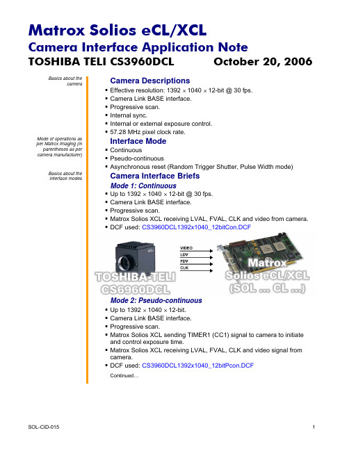
camera. DCF used: CS3960DCL1392x1040_12bitPcon.DCF
Continued…
parentheses as per camera manufacturer)
Basics about the interface modes
Camera Descriptions
Effective resolution: 1392 × 1040 × 12-bit @ 30 fps. Camera Link BASE interface. Progressive scan. Internal sync. Internal or external exposure control. 57.28 MHz pixel clock rate.
Camera Interface Application Note
TOSHIBA TELI CS3960DCL
October 20, 2006
Specifics about the interface modes
Camera Interface Details (cont.)
Mode 1: Continuous
Exposure time: The width (rising edge to falling edge) of the EXPOSURE1 (CC1) signal is the exposure time. To modify the exposure time, change the active duration of Timer1 in Matrox Intellicam or with the MIL MdigControl() function. It is recommended that the total period (active and inactive) of Timer1 be set to greater than the frame readout and exposure duration. Furthermore, any increase or decrease to the exposure time will respectively decrease or increase the frame rate.
快速启动指南 HR155 监听设备说明书
FRONT PANEL
STEREO IN: 1/8" TRS jack (3.5mm) stereo for connection to a line level signal.
VOLUME: Adjusts the output volume level of the HR155.
DESCRIPTION
REAR PANEL
XLR Input: XLR balanced input for connection to any standard line level XLR output.
INPUT: RCA stereo for connection to any line level RCA output.
HR155
Speaker Monitor Nhomakorabea6 75889 01550 8
Rolls Corporation Salt Lake City, UT
5/22
SPECIFICATIONS Input Impedance: THD + Noise: Voltage Gain: Connectors: Supply Voltage: Size: Weight:
10K Ohms .05% Typical 20 dB line 1 Female XLR, 1/8" TRS, 1 - RCA DC Power Jack 15 VDC 6.75" x 3.125" x 1.75" 1.25 lbs.
Quick Start Guide
INTRODUCTION
Thank you for your purchase of the HR155. This unit is designed and manufactured to monitor sound from any stereo RCA line level output or a single balanced XLR at line level. The front panel stereo 3.5mm (1/8" jack) input provides a convenient way to monitor a signal without accessing the rear of the unit. The is a HR155 a valuable tool for any sound reinforcement, recording, or install application that needs to monitor sound from a rack mounted unit.
- 1、下载文档前请自行甄别文档内容的完整性,平台不提供额外的编辑、内容补充、找答案等附加服务。
- 2、"仅部分预览"的文档,不可在线预览部分如存在完整性等问题,可反馈申请退款(可完整预览的文档不适用该条件!)。
- 3、如文档侵犯您的权益,请联系客服反馈,我们会尽快为您处理(人工客服工作时间:9:00-18:30)。
第4页
产品用户手册
高保真监听头
以色列E.TRADIO专业的环境声音(有线)监听探头,国内OEM生产。 高保真、语音清晰、噪音低。 镀银震膜电容咪头,本底噪声小、采音更广泛。 自适应动态降噪处理,内置高速DSP数字信号处理器。 独特设计的“电子噪声动态闭环抑制电路”,彻底消除“嘶嘶”电子噪音。 表面喷涂德国FLAYER漫射涂层,完美收音。 AGC自动增益、声音自动均衡,监听面积可达50平方米。 自动抑制高强度声音,可靠保护后端设备。 回声消除凹腔有效减少空旷房间的严重回音影响。 采用0.8mm针孔式设计,其内部共振声腔经过精确计算,收音更清晰。 超长线路传输专利技术,采用3芯0.5mm2 RVVP屏蔽电缆传输3公里不失真。 传输线的技术指标要求低,电话线、5类网络双绞线、屏蔽电缆等均可使用。 集成专业前置放大器,直接驱动有源音箱、硬盘录像机、耳机、录音机等。 噪音小、音质好、价格中等,适用于要求较高的工程应用。 抗回声、抗啸叫,适用于审讯室、会议室等空旷房间安装。 符合欧盟CE标准以及最高检同步录音录像系统建设规范。
一份 一台 (需要另外订购) 一台 (需要另外订购)
第三章 安全注意事项
不要在靠近水源的地方使用, 只能用湿布进行表面清洁。 不要向监听头喷洒液体,否则会毁坏监听头电路。 按手册指示安装监听头。 不要将监听头安装在有热源的地方,如:微波炉、电暖器、火炉、功率放大器等。 不要拆除电源的安全保护地线,确认电源不会被挤压或踩踏,尤其是电源线的两端。 尽量使用我公司提供的配件或附件。 与标准的专业音响设备配接使用,充分发挥其效能。 在安装时,确认移动连接线时不会对设备或人身造成危害。 雷电天气或长期不使用,请将此有保存好。 为专业维修人员提供详细的维修信息。当监听头出现问题,包括:电源线损坏、液体 或其他物品进入监听头内部、监听头受雨淋或受潮时、工作不正常、或从高处摔落 时,请勿自行修理。 通常,在工作时监听头会有一些发热,在通风干燥处使用,保持与其他设备距离10厘 米以上。 此监听头与功率放大器及耳机或音箱配合使用时,可能会产生损坏听力的高声压,不 要长时间在高声压或感觉刺耳的条件下使用如果您感觉到,听觉下降或耳鸣,您需要 去做听觉校正。 长期不使用时,将监听头包装好,保持干燥,注意防潮。
参数
性能指标
参 数 性能指标
监听面积
10平方米~100平方米
音频传输距离 3000米
频率响应
20Hz ~ 20kHz
灵敏度
-30dB
信噪比
70dB (1米40dB音源)
40dB (10米40dB音源)
指向特性
全方向性(全指向)
动态范围
104dB(1KHz at Max dB SPL)
最大承受音压 120dB SPL (1KHz,THD 1%)
输出阻抗
600欧姆非平衡
输出信号幅度 2.5Vpp/-25db
麦克风
高灵敏度全指向电容咪头
信号处理
DSP数字降噪, AGC增益
参 数 性能指标
保护电路 雷击保护、电源极性反转保护
适配器 全内置,可直连DVR、有源音箱
连接方式 3条引线 (电源,音频,公共地) 传输线缆 3芯0.5mm2 RVVP电缆、电话线等
目录
第一章 前言 ..............................................1 第二章 成套监听头及配件 ...............................2 第三章 安全注意事项 .....................................2 第四章 简介 ................................................3 第五章 安装监听头 .......................................10
TRADIOTM 监听头(拾音器)产品是我公司生产的音频拾音套件,专门针对安防行业的同 步录音录像监控设备所配套设计。TRADIO监听头外形简洁美观、性能卓越,投放市 场以来受到广大客户的好评。该监听头采用经过严格挑选的进口电容咪头,具有很好 的拾音特性,可根据不同场合需要选择使用。 TRADIO监听头根据其监听面积、声音品质、噪声大小以及定向特性分为近十款产 品。 该系列监听头性能好、经久耐用、频响效果好、音色圆润、音调柔和。放大器部分采 用了低噪声前置放大器,性能稳定,失真小,噪声低。其配置齐全,使用方便,而特 别适合于审讯室、看守所、监仓、机场安检通道、电化教室、银行大厅、上访接待 处、招标会议室等场所的录音。
电源电压 直流稳压电源 DC 12V (8V-18V)
电源电流 30 mA
环境温度 -25℃ ~ 70℃
颜色
银灰色
外壳材质 防尘不锈钢网 优质铝质基座
外形尺寸 120mm×30mm
重量
160 克
产地
以色列套件 中国组装
符合标准 欧盟CE标准,检察院录音录像规范
第3页
产品用户手册
烟感式监听头
以色列S.TRADIO专业的环境声音(有线)监听探头,国内OEM生产。 高保真、语音清晰、噪音低。 低噪声大型震膜全向咪头,采音更为广泛。 多级动态降噪处理,内置高性能语音DSP数字信号处理器。 独特设计的“电子噪声动态闭环抑制电路”,彻底消除“嘶嘶”电子噪音。 AGC自动增益、声音自动均衡,监听面积可达80平方米。 自动抑制高强度声音,可靠保护后端设备。 按照国际标准烟感器设计,便于室内天花板吊顶安装。 采用灵巧的旋转卡口,拆卸灵活。 集成专业前置放大器,直接驱动有源音箱、硬盘录像机、耳机、录音机等。 超长线路传输专利技术,采用3芯0.5mm2 RVVP屏蔽电缆传输3公里不失真。 传输线的技术指标要求低,普通电话线、网络双绞线、屏蔽电缆等均可使用。 内置雷击保护、电源极性反转保护。-25℃ ~ 75℃的超强工作温度范围。 噪音小、音质好、价格适中,适用于要求较高的工程应用。 抗回声、抗啸叫,适用于审讯室、会议室等同步录音录像工程。 符合欧盟CE标准以及最高检同步录音录像系统建设规范。
第1页
产品用户手册
第二章 成套监听头及配件
您购买的监听头在出厂前经过严格的测试,包装箱是为了防止在运输过程中对监听头 造成损坏。建议您将包装箱保存好,一旦将来需要维修服务或搬运时,可以对此监听 头进行防护。
纸包装箱内应包含如下附件:
监听头 用户手册 一本 保修卡 监听头电源 监听头适配器
一个
TRADIO监听头的特色是什么?
TRADIO监听头还集成了先进的的噪声处理、回声处理以及长距传输驱动电路以适应 更高标准和特殊需求的安防工程,以其高保真的音质忠实地记录和还原现场。 TRADIO监听头解决的最大技术难点是:麦克风灵敏度提高的同时,引入的噪声也会 大大增加,从而造成拾音混沌不清、无法听清。TRADIOTM 电声专家一举解决了困扰 音频监控行业的噪声控制问题。 此外,TRADIO监听头还巧妙地妥善解决了声音长距离传输引起的语音信号衰减及噪 声增加的问题。
TRADIO中国推广
2005年,以色列TRADIOTM 品牌的监听头首次引入中国,以其清晰自然的高保真音质 改变了以往质次价廉的音频监控工程形象。 2006年,TRADIO监听头大量应用于全国检察院和公安局的审讯同步录音录像。 2007年,中国生产并改良的TRADIO监听头返销国外市场。 2008年,首都机场T3航站楼安装数百只TRADIO监听头,为奥运安保提供服务。
输出阻抗
600欧姆非平衡
输出信号幅度 2.5Vpp/-25db
麦克风
大型震膜电容咪头
信号处理
DSP数字降噪,AGC增益
保护电路 适配器 连接方式 传输线缆 电源电压 电源电流 环境温度 颜色 外壳材质 外形尺寸 重量 产地 符合标准
雷击保护、电源极性反转保护 全内置,可直连DVR、有源音箱 四个端子:电源、音频、两个公共地 3芯0.5mm2 RVVP电缆、电话线等 直流稳压电源 DC 12V (8V-18V) 30 mA -25℃ ~ 70℃ 白色 PVC 103mm×50mm 80 克 原产地:以色列 中国OEM生产 欧盟CE标准,检察院录音录像规范
监听头是什么?
监听头也称拾音器,是用于同步录音录像监控的拾音配件。形象地说:摄像头是眼 睛,监听头就是耳朵。硬盘录像机负责存储声音和图像,监视器和音箱则用于回放。
监听头是麦克风?
不全对。监听头不但包含高灵敏度麦克风,还集成前置放大电路。因此,监听头可以 直连DVR、有源音箱、耳机、声卡等,而麦克风还需连接功放。另外,普通麦克风通 常是定向的和低灵敏的,在很近的距离对准了说话才行。监听头为了拾音更远,大多 被设计成高灵敏度、无方向或全指向性的。
附录 声学常识............................................20
产品用户手册
第一章 前 言
感谢阁下的信任购买TRADIOTM 系列监听头(或称拾音器)。本手册对此监听头(拾音器) 作了详细介绍,为了能长期正确使用,并充分利用它的所有功能,建议您在使用前认 真阅读此用户手册。
用户手册
版权声明
本手册为本公司版权所有。在未经书面许可的前提下不得以任何形式或方法复印、 传播、转录、存档或翻译成其他语言及电脑语言。公司品牌和产品名称TRADIOTM 为 商标或注册商标。本公司不对本文的内容作转述和承诺,特别不对商品作暗示性承 诺。本公司保留修改本手册的权利,无须提前通知其他方而变更本文。在未经本公司 许可的前提下,不得部分或全部复制本手册。
参数
性能指标
监听面积
10平方米~150平方米
音频传输距离 3000米
频率响应
20Hz ~ 20kHz
灵敏度
-30dB
信噪比
80dB ( 1米40dB音源)
(10米40dB音源)
指向特性
全指向性
动态范围