Synventive 热流道使用手册(部分).pdf
热流道技术介绍

分流板控温:
•热流道的组成及相关部件
热咀控温:
•热流道的组成及相关部件
工业重载连接器
•热流道的组成及相关部件
•温控器 作用:
精确控制热流道系统各个位置的温度。
特点:
针阀式结构较为复杂,通过油缸或气缸联接阀针来控制浇口的开与关,可 以根据实际需要设置热咀的开关顺序,从而控制每个热咀的注射顺序和出 胶量,以满足产品的特殊要求,如浇口痕迹小质量高、控制熔接线的位置、 多腔模具的注射质量平衡、防止浇口拉丝等,但生产成本较高;
开放式
•热流道系统的分类
开放式热流道结构较简单,在整个产品的生产过程中浇口都是常开的, 浇口容易出现拉丝或流涎现象,浇口处的温度控制要求比较精确,对注 塑机调机员技能要求较高,但是生产成本低,价格便宜。
1、插卡式结构(易于更换) 2、数字显示; 3、可设定J和K型; 4、测量范围0~450℃ 5、使用环境220VAC 6、可承受最大电流15A
•时序控制器
•热流道的组成及相关部件
作用:控制热流道阀针的打开顺序及保持状态的时间
特点:可以控制每个阀针的延迟、打开、关闭及维持 时间
注意:阀针的动作必须是在注塑信号结束前完成
分体式
•热流道系统的分类
分体式热流道是目前国内市场上最为常见一种形式,它的设计和加工都相对 较为简单,广泛应用在家电和电子类产品的模具上,适用于小型模具,目前 Mold-master、DME、HASCO、HUSKY、YUDO、以及国内的热流道公司 所生产的热流道系统,大都以此类形式出货,但是此类热流道的安装和维护 较为麻烦,结合面容易出现渗胶或漏胶现象,需要专业人士进行安装;
内联化学热器操作与维护指南说明书
INLINE DIHEATEROperation / MaintenanceManualSERIAL NUMBER:PATENTS: U.S. 5971402, U.S. 6433319, U.S. 6479094B2, U.S. 6544583B2, 8/16/2018 – MID U.S. 6580061B2, U.S. 6663914, U.S 6674053B2;CONTENTS1INTRODUCTION (3)1.1INTENDED USE AND AUDIENCE (4)1.2HEATER SIZING (4)2SAFETY (6)2.1SAFETY PRECAUTIONS (6)2.1.a General Safety (6)2.2SAFETY MESSAGE CONVENTIONS (7)2.2.a Caution (7)2.2.b Warning (7)2.2.c Danger (7)2.3HEATER INTERLOCKS (7)2.3.a Leak Sensor (7)2.3.b Element Over-Temperature Protection (8)2.3.c Liquid Over-Temperature Protection (8)2.3.d Internal Over-Temperature Protection (9)2.3.e Liquid Level Sensor Interlock (9)3INSTALLATION (10)3.1UTILITY REQUIREMENTS (12)3.2UNPACKING (12)3.3ORIENTATION (12)3.4FLUID CONNECTIONS (12)3.4.a Inlet & Outlet (12)3.4.b Liquid Drain (13)3.5ELECTRICAL CONNECTIONS (13)4OPERATION (14)4.1GENERAL (14)4.2LIQUID START-UP (14)4.3TEMPERATURE CONTROL (15)4.4SHUT DOWN (15)5MAINTENANCE (17)5.1SPARE PARTS (17)5.2PREVENTIVE MAINTENANCE SCHEDULE (17)5.3REMOVAL AND REPLACEMENT INSTRUCTIONS (17)5.3.a Heater Replacement (17)5.3.b Heater Decommissioning (17)5.3.c Heater Disposal (17)6TROUBLESHOOTING (18)6.1IRREGULAR TEMPERATURE CONTROL (18)6.2HEATER ELEMENT CHECK (18)6.3INTERLOCK SENSORS (19)7WIRING SCHEMATIC (20)8OPTIONS (22)8.1FLUID CONNECTIONS (IDA04V208SB08AA): (22)8.2LEAK SENSOR (IDA04V208SB08AA): (22)8.3INTERLOCK TEMPERATURE SENSORS (IDA04V208SB08AA): (22)9WARRANTY AND EXCLUSIONS (23)10CONTACT INFORMATION (24)10.1GENERAL CONTACT INFORMATION (24)10.2TECHNICAL SUPPORT (24)10.3REGIONAL REPRESENTATIVES (24)1 INTRODUCTIONInline DI Heater - The Smart Choice!Trebor’s ID quartz inline DI water heater provides the ultra-high purity you demand, with the reliability you expect.The ID heater’s flow path is smooth, free of particle traps and constructed entirely of GE 214 quartz, PTFE and PFA. Most importantly, unlike immersion style resistive heaters your application is free from metal ion contamination risk if the external thin-film heating element should fail.Trebor’s patented sealing technology not only protects against liquid leaks, but eliminates the breakage commonly associated with fragile quartz fluid connections. Plus, there are no O-rings to service or replace.Simplicity and flexibility are key elements of the ID heater. The modular design allowsheaters to be connected in parallel or series. Heaters are available in multiple voltages and with multiple fluid fitting options to accommodate your heating needs.Features∙Quartz/PFA liquid path∙Multiple fluid fitting options∙No metal contamination risk∙No particle traps∙Efficient heat transfer and small thermalmass for fast response∙SEMI S2, S3, and CE compliantPerformance Summary1.1 INTENDED USE AND AUDIENCEThe ID heater is designed to safely heat DI water up to 100°C. The ID heater is not intended for use with combustible or flammable chemistries, such assolvents, or chemistries such as HF or KOH with accelerated quartz etch rates.This manual only covers the Trebor ID heater and heater accessories provided by Trebor. The user is responsible for the external control system and allnecessary connections required to safely operate the heater (see Sections 4.3and 7)The Trebor ID heater is not to be used for proposes other than that which isdesigned for. The heater and optional components are to be used only withliquids and parameters stated within this manual. This manual assumespersonnel are familiar with the installation, operation and maintenancerequirements of DI water heaters.The ID heater is intended for use by properly trained personnel. Read andunderstand this manual prior to installation and/or operation of the heater. Donot use this equipment until familiar with its operation and safety features.1.2 HEATER SIZINGIn order to maximize efficiency and the lifeof the heater, it is best to maximize flowthrough the heater. When using multipleheaters in low flow applications (usuallysingle pass) plumbing the heaters inseries is generally the best. If using highflows and pressure drop is a concern,plumbing the heaters in parallel is best.Parallel Series Use Figure 1-1 or the formula below to determine the required heater(s) size for the application.NOTE: Figure 1-1 shows approximate temperature change in water.Figure 1-1Sizing Formula: 1.25×(.264×GPM× ∆°C) =kW Required Conversions:GPM =LPM3.8×(∆°F−32)∆°C =592 SAFETY2.1 SAFETY PRECAUTIONSThis section provides important information for safe operation of the ID heater.The equipment described in this manual uses hazardous voltage that can bedangerous. Local policies and procedures for safely operating any Treborchemical heater(s) supersede the safety considerations listed below. It is theresponsibility of all personnel to follow such policies and procedures. All safetyguard devices must be in place when equipment is in operation. Operators, set-up operators, helpers or installation personnel should not alter, remove or disable safety devices or equipment.If the inline heater is used in a manner other than stated in this operation manual, the protection provided by the heater may be impaired.2.1.a General Safety∙There are no serviceable parts inside the heater assembly; never open or disassemble. Attempting to do so will void the product warranty.∙Do not attempt to work on or with hazardous chemicals or electrical equipment without proper safety training and certification, understand first aidfor electrical shock and hazardous chemicals spills.∙Lockout and tag the electrical and chemical systems prior to installation or replacement. Refer to company safety policies and procedures prior toinstallation or replacement.∙Always disengage the heater and optional equipment from electrical sources prior to installation or replacement.∙Always refer to company safety policies and procedures for flushing and decontamination prior to removal.2.2 SAFETY MESSAGE CONVENTIONS2.2.a CautionA Caution message indicates a potentiallyhazardous situation, which, if not avoided, could result in minor or moderate injury. It may also be used to alert against unsafe practices. A typical Caution message:CautionCorrosive Chemical2.2.b WarningA Warning message indicates a potentiallyhazardous situation that, if not avoided,could result in serious injury. A typicalexample of a Warning message:WarningHazardous Voltage2.2.c DangerA Danger message indicates an imminently hazardous situation that, ifnot avoided, will result in death or serious injury. Messages identified bythe word Danger are used sparingly and only for those situationspresenting the most serious hazards2.3 HEATER INTERLOCKS2.3.a Leak SensorThe Trebor ID heater is supplied with a 24Vdc conductive liquid leaksensor. Note, two modes of operation are available – NPN (normallyopen) and PNP (normally closed).An integrated magnetic reed switch allows a non-intrusive method forverification of sensor operation. Pass a strong magnet around the bottom of the heater just out from the drain plug to engage the reed switch andtrigger the leak sensor see Figure 2-1. If magnet is not strong enough,remove the drain plug and move magnet into drain hole for testing.See Section 7 for wiring instructions.Figure 2-1Note: The heater has no provision for monitoring or controlling flow ratesor provisions to turn off flow to the heater during a leak alarm. It isrecommended that the user incorporate a separate interlock to isolateflow and power from the heater in the event of an alarm.2.3.b Element Over-Temperature ProtectionThe Trebor ID heater is supplied with a temperature sensor(s) located on the heater element. The element temperature sensor(s) must be usedwith an interlock to ensure the element temperature does not exceed250°C.Note: Two types of sensors are available – thermocouple and RTD. SeeSection 7 for wiring instructions.2.3.c Liquid Over-Temperature ProtectionThe maximum liquid temperature (T max°C) can be estimated from theelement temperature (T e°C), heater power rating (P - i.e. 3-kW, 4-kW, 6-kW, etc.) and duty cycle (duty %). T e = T max + P * duty * 16.1Example 1: Given a maximum allowable liquid temperature of 140°C, aheater rated at 6 kW and a 100% duty cycle, the maximumelement temperature limit is:T e = 140°C + (6)*(1.00)*(16.1)T e = 236.6°C (Maximum allowable element temperature) Example 2: Given a maximum allowable liquid temperature of 140°C, aheater rated at 6 kW and a 75% duty cycle, the maximumelement temperature limit is:T e = 140°C + (6)*(0.75)*(16.1)T e = 212.5°C (Maximum allowable element temperature) 2.3.d Internal Over-Temperature ProtectionThe Trebor ID heater is supplied with a temperature sensor(s) locatednear the top of the quartz substrate. The control system must limit thequartz substrate temperature interlock sensor to a maximum temperatureof 200°C. Note, two types of sensors are available – thermocouple andRTD. See Section 7 for wiring instructions.2.3.e Liquid Level Sensor InterlockThe Trebor ID heater requires a liquid level interlock with a sensor located at the heater outlet to prevent dry operation, see Figure 2-2 for example.See Section 7 for wiring instructions for Trebor’s optional liquid levelsensor.Figure 2-23 INSTALLATIONEnsure that all heater interlock and safety devices are functional prior tooperation (refer to Section 2, Safety Requirements). Before starting the system, it is important to read and understand Section 4, Operation. Only trained,qualified, authorized personnel should operate this heater.Use 3/8” –7/16” bolts or equivelant to mount bracker to ½” or thicker UHMW or equivelant structural wall.Figure 3-1Figure 3-23.1 UTILITY REQUIREMENTSUtility CHEMICAL HeaterSystem Power: ∙3kW 208 Vac 50/60 Hz, 1Ø, 20 Amp Service∙4kW 208 Vac 50/60 Hz, 1Ø, 25 Amp Service∙4kW 240 Vac 50/60 Hz, 1Ø, 25 Amp Service∙4kW 400 Vac 50/60 Hz, 1Ø, 15 Amp Service∙6kW 400 Vac 50/60 Hz, 1Ø, 20 Amp Service∙3kW 400 Vac 50/60 Hz, 3Ø, 20 Amp Service∙4kW 400 Vac 50/60 Hz, 3Ø, 25 Amp Service∙6kW 400 Vac 50/60 Hz, 3Ø, 30 Amp Service Maximum Pressure 5.5 Bar (80 pisg)Heater Weight: (Approximate)∙ 3 & 4 kW – 4.3 Kg (9.4 lbs.) dry ∙ 6 kW – 5.6 Kg (12.4 lbs.) dry3.2 UNPACKINGThe system should be checked for any damage that may have occurred duringshipment. Damage should be reported to the carrier immediately.The following items should be contained within the shipping container:QTY. DESCRIPTION1 ID Heater / Optional Accessories1 Operation / Maintenance Manual3.3 ORIENTATIONThe heater must be positioned within 15° of vertical. Horizontal mounting willreduce heater life and void warranty. The heater should be installed so that theweight of the heater is either supported by the heater mounting bracket or othersystem that prevents the support of the heater on the plumbing.3.4 FLUID CONNECTIONS3.4.a Inlet & Outlet∙Attach the inlet and outlet fluid connections following the fittingmanufacturer’s procedures. Fluid connections are located at the bottom(inlet) and top (outlet) of the heater, see Figure 3-1.∙Verify flow direction.∙TREBOR recommends operating the heater with DI water for two or more thermal cycles to visually inspect for leaks prior to operation.3.4.b Liquid DrainA housing drain plug is located at the bottom of the heater to drain off anyliquid that may be present inside the housing, see Figure 3-1.3.5 ELECTRICAL CONNECTIONSConnection of required electrical hook-ups is required between the heater andcontrol system. See Section 7 for wiring instructions.4 OPERATION4.1 GENERALEnsure that all heater interlock and safety devices are functional prior to operation (refer to Section 2, Safety Requirements).The ID heater is designed to heat DI water in either single pass (trim) or recirculation applications up to 100°C (minimum flow of 2lpm for IDAconfiguration). Figure 4-1 shows approximate flow capacity versus temperature rise per fluid pass of water.Water should maintain at least 2 lpm (.53 gpm) of flow and .10 MPa (15 psig) of pressure to prevent boiling of the fluid near the element.Figure 4-14.2 LIQUID START-UP∙ Ensure that plumbing is secure. ∙ Turn “On” the liquid supply.∙ Check for leaks in the system plumbing.Change in Temperature per Fluid Pass (H20)0°10°20°30°40°50°60°70°80°90°246810121416182022242628303234363840Flow (lpm)ΔT (°C )3kW 4kW 6kW 12kW∙Allow the liquid to run through the system approximately 2 minutes prior to energizing the heater.4.3 TEMPERATURE CONTROLAn external control system is required for operating the ID heater; see Figure 4-2 for a typical control set up. The system should consist of: temperature controlsystem, interlock controls (see Section 2.3), and outlet liquid temperaturesensor(s). Operating settings and parameters are to be determined by the user.The control scheme should be set up to not only control the liquid outlettemperature but also limit the heater element surface temperature to a maximum of 250° C (see Section 2.3.b).The control system should supply a pulse width with a period less than 1 second.The main Circuit breaker must be in close proximity to the equipment and withineasy reach of the operator. It also must be marked as the disconnecting devicefor the heater. The circuit breaker should be sized according to the breakermanufacturer’s specificatio n (generally this is max current draw +25%) and theheater size shown in Sec. 3.1.Figure 4-24.4 SHUT DOWNThe following procedure should be used to safely shut down the heater:∙Cut-off power to the heater.∙Allow liquid to pass through the heater for at least 5 minutes or until the outlet temperature drops below 50°C.Note: The user is responsible for providing an EMO circuit to interlock their entire system. This device can also be used to disengage heater power.5 MAINTENANCE5.1 SPARE PARTSThere are no spare parts for the IC heater.5.2 PREVENTIVE MAINTENANCE SCHEDULEThe IC heater requires no preventive maintenance.5.3 REMOVAL AND REPLACEMENT INSTRUCTIONS5.3.a Heater ReplacementThe IC heater has been designed for quick replacement to minimizedowntime and field service requirements. To replace a heater, use thefollowing procedures:∙Shut down per Section 4.4.∙Turn power off to system (electrical and liquid).∙Drain liquid from heater housing (if present).∙Flush and/or decontaminate per company policy.∙Disconnect the electrical connection and interlocks to the heater.∙Drain liquid from the heater (if present).∙Disconnect the fluid inlet/outlet connections.∙Remove heater assembly.∙Install replacement heater per Section 3.∙Start-up per Section 4.2.∙Contact Trebor or a factory authorized representative for returnprocedures, if required.5.3.b Heater DecommissioningHeater assemblies removed from service, decommissioned, ordismantled should follow the steps outlines in Section 5.3.a for removingthe heater assembly.5.3.c Heater DisposalHeater assemblies being disposed are to be disposed of per companypolicy.Residual housing chemistry can be drained per the heater housing drainport located on the inlet side of the heater. All drained chemistry is to bedisposed of per company policy.6 TROUBLESHOOTINGThe following is an outline of routine troubleshooting techniques. For conditions not covered in this section consult Trebor or a factory authorized representative.6.1 IRREGULAR TEMPERATURE CONTROL6.2 HEATER ELEMENT CHECKLockout and Tagout power to the heater. Disconnect the heater power electrical connections and measure the resistance between power wires or to the neutral wire. Resistance should be less than the values listed in Table 6-1.6.3 INTERLOCK SENSORS7 WIRING SCHEMATIC∙Heater Power Wiring (IDA04V208S B08AA):∙Heater OTC Signal Wiring (IDA04V208SB08A A):∙Heater Internal Leak Wiring (IDA04V208SB08A A):Heater Wiring Schematic:Figure 7-18 OPTIONS8.1 FLUID CONNECTIONS (IDA04V208S B08AA):∙¼” Flare (Option F04)∙½” Flare (Option F08)∙¾” Flare (Option F12)∙¼” Super 300 Pillar® (Option X04)∙½” Super 300 Pillar® (Option X08)∙¾” Super 300 Pillar® (Option X12)Super 300 Type Pillar® is a registered trademark of Nippon Pillar Packing Co. LTD 8.2 LEAK SENSOR (IDA04V208SB08A A):∙24Vdc NPN style normally open (Option A)∙24Vdc PNP style normally closed (Option B)8.3 INTERLOCK TEMPERATURE SENSORS (IDA04V208SB08A A):∙Type “J” thermocouple (Option A – Standard 1Ø)∙PT1000 RTD (Option B – Standard 3Ø)∙PT100 RTD (Option C)∙Type “K” thermocou ple (Option D – Standard 1Ø)9 WARRANTY AND EXCLUSIONSSee the Trebor Standard Limited Warranty at/support/trebor/downloads/TreborStandardLimitedWarranty_02-07.pdf10 CONTACT INFORMATION10.1 GENERAL CONTACT INFORMATIONWeb: Phone Number: (801) 561-0303Toll Free Number: (800) 669-1303Fax Number: (801) 255-2312Email: *********************************************** Address: Trebor International8100 South 1300 WestWest Jordan, Utah 84088 U.S.A.10.2 TECHNICAL SUPPORTEmail: **************************Phone Number: (801) 244-615610.3 REGIONAL REPRESENTATIVESWeb: 。
热流道控制器用户使用说明书

热流道控制器用户使用说明书产品使用前,请仔细阅读说明书,以便正确使用,并妥善保存,以便随时参考。
断电后方可清洗仪表。
清除显示器上污渍请用软布或棉纸。
显示器易被划伤,禁止用硬物擦拭或触及。
禁止用螺丝刀或书写笔等硬物体操作面板按键,否则会损坏或划伤按键。
1.在使用前先检查控制器⑴检查控制器的配件是否齐全⑵检查电源是否安全受控⑶检查此说明书是否与控制器匹配⑷检查连接器是否安全可靠⑸检查加热器是否安全可靠⑹检查主电源是关闭的⑺检查电源是否适合控制器的工作⑻确定地线连接控制器⑼打开主电源开关⑽打开各个控制器工作开关⑾设定控制温度⑿检查控制器是否达到设定温度,且稳定2. 控制器输出⑴PID控制通过测量实际温度和设定温度进行比较,精确计算比例、微分、积分值,控制输出电压⑵自整定通过分析加热器和加热模式排除环境变化调整控制参数⑶输出模式根据电源环境确定●50赫兹●60赫兹3. 技术参数输入电压:AC 85V-250V,50/60HZ,15A负载能力:15A,150W-1650W(110V),100W-3300W(220V)输出类型:PWM传感器:热电偶(K \ J)温度范围:100℃~400℃温度稳定性:±0.5%温度控制类型:PID 控制环境温度:-10℃~50℃4.面板布局1.指示灯:状态指示灯(STATE):软启动常亮,预整定1秒闪烁,自整定0.5秒闪烁,其他状态不亮。
输出指示灯(OUT):指示输出的的状态。
自动指示灯(AUTO):指示自动模式被选择。
等待指示灯(STANDBY):指示等待模式被选择。
手动指示灯(MANUAL):指示手动模式被选择。
2.数码管:PV数码管,红色,显示测量温度和参数代码。
SV数码管,红色,显示设定值和参数代码值。
3.按键::输入键:模式键:AUTO、STANDBY、MANUAL模式转换键:增加键:减小键5.操作模式通过按SEL键1秒钟以上可以进入以下模式。
⑴自动模式:正常的PID控制,在正常的设定值上。
Synventive 热流道系统 说明书

圣万提注塑工业(苏州)有限公司 用户手册 修订本 0.3热流道系统用户手册引言亲爱的客户感谢您使用圣万提的热流道系统,基于多年的设计和生产经验,我们有信心为您提供高质量的产品,使用中如有任何疑问,请随时和我们联系。
此手册所包含的基本信息适用于圣万提所有的热流道系统,是正确安装、操作、维护的参考书,也是如何健康安全使用热流道系统的指导书。
为保证产品的使用寿命、确保操作者的人身安全,要求用户必须严格遵循手册内容。
热流道系统必须由专业人士安装操作,用户应为自身的安全和设备的完好性负责,圣万提不对因不当使用、安装及操作导致的损伤或损坏负责。
用户应采取必要的安全防护措施如佩戴安全手套、安全耳套、安全眼罩等等。
此文件中可能不包含所有的应用注意事项,因此用户操作时必须遵循基本的及其公司内部要求的操作安全规定。
我们对产品的建议出于我们对产品的了解,用户可遵循但不应局限于此。
用户可处于自身的考量和计算调整,从而使产品和注塑机及其他设备更好地配合,从而更好地满足注塑过程的需求。
手册旨在为使用热流道模具的加工、生产和注塑人员设计,如果您是工具制造商,请将此手册转交给注塑模具的最终用户。
您忠实的圣万提注塑工业有限公司销售中心USA – Peabody, MA Synventive Molding Solutions 10 Centennial Drive Peabody, MA 01960Tel.: +1 800 367 5662 Tel.: +1 978 750 8065Fax: +1 978 646 3600 Email:*******************Deutschland – BensheimSynventive Molding SolutionsGmbHHeimrodstraße 10P. O. Box 312364625 BensheimTel. :+49 (0)6251 9332-0Fax :+49 (0)6251 9332-90Email:***********************中国 – 苏州圣万提注塑工业(苏州)有限公司苏州工业园区港田工业坊12B215021电话: +86 512 6283 8870传真: +86 512 6283 8890Email:***********************此文件包含重要机密信息,版权归圣万提注塑工业,任何个人或机构在未取得圣万提书面授权的情况下不得全部或部分复制、出售给任何第三方机构及个人。
Sporlan Type NX 热扩散阀门说明书
Page 2 – Bulletin 10-10-10Type NX ValvesThermostatic Expansion ValvesThe small and compact design of Sporlan’s Type NX ThermostaticExpansion Valves makes this product ideal for foodservice and foodretail applications such as display cases, ice machines, frozen drinkdispensers and commercial kitchen refrigerators and freezers.The Type NX valves feature a laser-welded stainless steel element,capillary tube, and sensing bulb assembly optimized for reliability andlong life. The single pushrod balanced port design ensures precise pinand port alignment, enabling the valve to maintain superior superheatcontrol at all load conditions.Features and Benefits• Long-lasting and durable stainless steel diaphragm and weld design• Single pushrod balanced port construction• Unique design minimizes solid debris build-up• Suitable for all common refrigerants including R-290• Internal or external equalizer• Easily adjustable superheat setting• High strength silver soldered joints with solid copper connectionsSporlan built the Type NX valve with a stainless steel capillary tube laser weldedto the sensing bulb and element housing to withstand the repeated bendingduring installation and improve endurance to vibrations while in service.The forged brass NX valve body is available with a straight-through flow config-uration and ODF (sweat) copper connections. The valve can be supplied witheither an internal or external equalizer and features a field adjustable superheat stem. Valves with fittings in metric sizes are available upon special request.Type NXEType SNXEBulletin 10-10-10 –Page 3Sporlan constructed the NX valve with a single, balance-ported pushrod which is specifically designed to helpflush out any solid debris build-up. The bleed port featureallows the system refrigerant to bypass the pin and port.System designers can utilize this feature to alter systemperformance for a variety of reasons. Bleed port optionsare available upon special request.New refrigerants continue to enter the refrigeration andair conditioning market to satisfy environmental andregulatory requirements. In the past, Sporlan assigned a letter code to each refrigerant. Now, they consolidated the Type NX valve models by refrigerant groups to simplify product application. Additionally, the Type NX valve is available with a 3-digit alphanumeric code indicating the valve’s pin and port combination, rather than a numerical “nominal” capacity.The NX element features a 30” standard length stainless steel capillary tube. Extended 60” capillary tube lengths are available upon special request.Standard static superheat settings vary based on thesystem refrigerant selected, but the valves are set toapproximately 4°F static superheat based on the newerrefrigerants such as R448A, etc. Special settings are avail-able upon special request.The seal cap utilizes a mechanical knife-edge seal. Thetorque required for proper sealing is 8 to 11 ft-lbs.Sporlan offers 2 optional inlet strainers for use with NXvalves; an insert strainer and an integral strainer.The insert type strainer is placed into the inlet fitting prior to brazing and can only be serviced by disconnecting the liquid line.The integral strainer, which is a feature of the SNX(E), is serviceable and allows for the strainer to be removed without disconnecting the valve from the liquid line. The integral strainer utilizes a mechanical knife edge seal. You can achieve the proper amount of torque by rotating ¼ turn past hand tight.SpecificationsThe Type NX valves offer a wide range of type W thermo-static charges with or without the MOP feature. You canuse the thermostatic charges with the MOP (maximumoperating pressure) feature to help protect the compressor from overloading at startup or under high load conditions. See the MOP temperature in the table below.Page 4 – Bulletin 10-10-10 Valve ModelsNXInternallyEqualizedNXEExternallyEqualizedSNXEBulletin 10-10-10 – Page 5Unlike other Sporlan Thermostatic Expansion Valves, itsitem number completely defines the type NX valve. Thestandard NX item number has 7 positions; however, itemnumbers can be up to 14 positions in length. Positions 8- 14 are reserved for special OEM configurations. Refer tothe following example of a standard NX item number andthe position descriptions when ordering.Nomenclature and Item Numbering SystemLike other Sporlan Thermostatic Expansion Valves, the Type NX valves follow the nomenclature example and ordering instructions below.Item NumberPosition DescriptionsItem Number and PositionsPage 6– Bulletin 10-10-10PackagingAll valves are packaged in clear plastic bags for protection.Standard NX valves are individually boxed with a bulbstrap kit and are packed 24 pieces per case.Egg crate style production packaging is available uponspecial request and valves come packed 36 pieces percase.AccessoriesIdentification and MarkingsSeveral valve identifications are laser marked on the ele-ment, as shown.The 5 digit date code indicates the day and year. The first 3digits represent the day of the year. The last 2 digits are theyear.The PTS Number is a Parker Sporlan serial number.Additional markings are on the forged brass body, includ-ing a flow direction arrow and the Sporlan trademark.Description Refrigerant Compatibility Parker Sporlan Item Number Date Code PTS Number 2D Data Matrix ElementBulletin 10-10-10 – Page 7Thermostatic expansion valve capacity ratings are basedon vapor free 100°F (38°C) liquid refrigerant entering theexpansion valve; a maximum opening superheat of 7°F(4K); and a standard factory air test superheat setting. Adiscussion of the relationship between valve capacity andsuperheat setting (along with other important applicationinformation) can be found in Bulletin 10-9.The valves are tested in accordance with ANSI/ASHRAE17. The ratings in the capacity tables are in accordancewith ANSI/AHRI Standard 750. It is possible to correct for both liquid temperature and pressure drop using the factors in the tables following the capacity tables. The liquid temperature correction fac-tors are refrigerant dependent, and tables are provided for each refrigerant. The pressure drop correction factor is affected by the valve and is independent of the refrigerant. The correction calculation is shown below, followed by an example calculation.TEV Capacity = TEV Rating x CF Liquid T emperature x CF Pressure DropExample Calculation: The actual capacity of a Type NX valve with a C38 capacity code on R448A at 20°Fevaporator temperature, 100 psi pressure drop across the TEV , and 90°F liquid temperature entering the TEV is:Actual Capacity = 2.07 (from rating chart) x 1.08 (CF liquid temperature) x 0.89 (CF pressure drop) = 1.99 tonsCapacity Ratings and SelectionkW ■ bar ■ °CPage 8– Bulletin 10-10-10kW ■ bar ■ °C Capacity Ratings and SelectionBulletin 10-10-10 –Page 9kW ■ bar ■ °C Capacity Ratings and SelectionPage 10– Bulletin 100-40-3■ bar ■ °C Correction FactorsCapacity Ratings and SelectionBulletin 10-10-10 – Page 11Dimensions - Inches (mm)Type NX(E)Front ViewT op ViewExternal 1/4” ODF Equalizer FittingType SNX(E)T op ViewExternal 1/4” ODF Equalizer FittingFront ViewBulletin 10-10-10 / 42021© 2021 Parker Hannifin CorporationParker Hannifin Corporation Sporlan Division206 Lange Drive • Washington, MO 63090 USA phone 636 239 1111 • fax 636 239 ⚠WARNING – USER RESPONSIBILITYFailure or improper selection or improper use of the products described herein or related items can cause death, personal injury and property damage.This document and other information from Parker Hannifin Corporation, its subsidiaries and authorized distributors provide product or system options for further investigation by users having technical expertise.The user, through its own analysis and testing, is solely responsible for making the final selection of the system and components and assuring that all performance, endurance, maintenance, safety and warning requirements of the application are met. The user must analyze all aspects of the application, follow applicable industry standards, and follow the information concerning the product in the current product catalog and in any other materials provided from Parker or its subsidiaries or authorized distributors.To the extent that Parker or its subsidiaries or authorized distributors provide component or system options based upon data or specifications provided by the user, the user is responsible for determining that such data and specifications are suitable and sufficient for all applications and reasonably foreseeable uses of the components or systems.OFFER OF SALEThe items described in this document are hereby offered for sale by Parker Hannifin Corporation, its subsidiaries or its authorized distributors. This offer and its acceptance are governed by the provisions stated in the detailed “Offer of Sale” available at .For safety information see the Safety Guide at /safety or call 1-800-CParker.。
维克ト顿能量VEFlash和VictronConnect用户指南说明书

Updating VE.Bus firmware, using VEFlash VEFlash is deprecated in favour of VictronConnectBeing both faster and easier to use, we now recommend to use VictronConnect for firmware updates. Instructions in the VictronConnect VE.Bus manual.Use VEFlash only for (older) models not supported by VictronConnect.Instructions for the old (deprecated) methodWarning: This operation must only be carried out by Victron-trained Engineers, Installers and Dealers, and must not be attempted by system Owners and Users.Updating firmware on a VE.Bus product (Inverters, Multis and Quattros) has system-critical implications:All settings will be lost - Save your settings first!Assistants and parallel or three-phase configuration will be lost.Setting up a VE.Bus system requires both training and experience. We offer no direct support for un-trained individuals carrying-out reconfiguration.These instructions are for the VEFlash firmware update method, it is also possible to update VE.Bus firmware with VictronConnect, which is available for Windows, macOS, and Android.NotesUpdating a VE.bus product can be done using VEFlash.exe which you will find in VE Configure Tools, available for download on our software page.New firmware files are available from Victron Professional (a free account is required).To select the right file, check the firmware version which is in the product now. Look for a seven digit number (eg. 2654153) which you'll find printed on a sticker on the control board. The first four digits indicate the model, and must match the first four digits of the file you intend toupload.There are different firmware types available. Read our PDF VE.Bus firmware versions explained carefully to select the best firmware for your system. For recent products, use the latest 400 version.Always use the latest version of VEFlash. It will automatically check online for updates onstartupWhen updating parallel or three-phase installation, update each unit separatelyAfter updating firmware, all settings will be reset to their factory defaults. The unit will be in stand-alone mode, and any Assistant settings will be removed.It is not required to keep your Victron equipment updated to the latest firmware version. Stable systems should be left with their current firmware. Firmware updates should only be done when it is recommended to fix an issue you are experiencing, or add a new feature that is required byupdate:updating_firmware:updating_ve.bus_products https:///live/updating_firmware:updating_ve.bus_products 2023-06-2910:48the installation.Step by step instructionsFollow the on screen steps.Save the Firmware file in an easy to find folder.update:updating_firmware:updating_ve.bus_products https:///live/updating_firmware:updating_ve.bus_products 2023-06-2910:48Follow these steps carefully.update:updating_firmware:updating_ve.bus_products https:///live/updating_firmware:updating_ve.bus_products 2023-06-2910:48Once finished and OK is selected the Inverter/Charger will reset itself.Note that all settings will be reset to defaults. Also that the unit will be reset to stand alone mode and any Assistant settings will be removed.DISQUSView the discussion thread.。
热流道技术资料一
热流道技术资料一熱流道的技術熱流道的技術與關注事項熱流道的主要功能之一是使熱流道內的塑膠熔體在模塑周期的注射、保壓和冷卻階段保持正確的加工溫度;其次是比較和緩的輸送塑膠熔體,使壓力和施加於其上的剪切應力降到最低。
所以,熱流道的使用及質素將會影響塑膠成品的最終表現,用戶必須徹底理解熱流道的各個組合及其設備。
封合概念在熱流道系統當中,樹脂流動時所經過的所有配對表面都要進行封合。
經常發生泄露的地方,就是注嘴與分流器之間的封合點。
對於未有預壓的注嘴(在未加溫下沒有得到實際封合),這樣的情況最容易發生。
這一類系統在設計上留有冷間隙--冷間隙是指在室溫下、在分流器板與墊模板範圍之內,各元件與總口徑深度之間的間隙。
在該系統升溫至操作溫度期間,這個間隙容許元件進行一定程度的膨脹。
爲了實現封合,這一操作溫度必須達到,才能形成足夠的表面壓力,去承受著將兩個元件撞開來的注射力。
帶有冷間隙的熱流道系統如果未完全達到操作溫度,就不會有足夠的表面壓力來防止泄露。
其中一個解決辦法是將一套片簧(disc spring)裝在注嘴的底部。
在該系統達到操作溫度之前,這些片簧將分流器牢靠地封合在注嘴上;如果發生過熱,片簧就會將過量的熱力膨脹吸收掉,從而避免過量膨脹造成元件奕形和泄露。
鑒於注嘴是經過"預先加壓"的,冷啓動(在該系統達到操作溫度之前注射樹脂)就不會造成泄露。
換言之,就是彈簧設計使操作範圍更寬,人爲錯誤儘量減少。
注嘴設計檢討市場上有好幾款注嘴設計,有些設計可容許更多錯誤,所以不太容易發生泄露。
下面我們來檢討一下這一類設計。
圖2A:設有主動型泄露保護特徵的實心套筒式設計圖2B:注嘴是從分流器的背面栓接過來的。
高溫螺杆將注嘴栓接到分流器上,並在冷狀條件下進行正向封合。
不過,該系統還是需要有冷間隙,因爲在操作溫度下,注嘴的實心套筒需要有一定的膨脹空間。
這種方法能對注嘴和集料管進行正向封合,但它並不能保護元件免受過熱引起的熱膨脹影響。
泰莱尔热量流量计模拟版112精密流动系2热量流量计说明书

2For more information call +1 603 595 1500 or email ppfinfo @Visit Typical Applications• Burner Ratio Control forCeramics and MetalsTraditional Analog Flow MeterModel 112Thermal Mass Flow MetersProduct SpecificationsParker Model 112 Thermal Mass Flow Meters provide reliable analog flow measurements configured for your process conditions. Each meter offers a linear flow signal output proportional to a calibrated flow rate and is available with a D-connector.Features• Cleaned for Analytical Service Use •RoHS and REACH compliantPhysical PropertiesPerformance RatingsElectrical3T h e r m a l M a s s F l For more information call +1 603 595 1500 or email ppfinfo @Visit Principle of OperationModel 112Thermal Mass Flow MetersParker Model 112 Mass Flow Meters (MFM) incorporate an operating principle based on the thermodynamic properties of the process gas being measured.Mass flow measurement relates to the amount of heat absorbed by the process gas. The amount of heat the gas absorbs is determined by the gas molecular structure. Specific heat, the amount of heat required to raise the temperature of one gram of a given gas onedegree centigrade quantitatively describes this “thermal absorbency”.Mass flow measurement consists of a bypass sensing tube with a heater wound around the center of the sensing tube and precision resistance type temperature sensors located equidistant upstream and downstream of the heater. A laminar flow element package, located in the main flow stream, acts as an appropriate restriction creating a pressure drop forcing a fixed percentage of the total flow, approximately 10 sccm, through the bypass sensing tube for temperature differential detection. As gas flows through the sensing tube, heat is displaced to the downstream temperature sensor creating a temperature differential between the upstream anddownstream temperature sensors. The upstream and downstream temperature sensors form two legs of a bridge network at the sensor assembly inputs to the PCB. The resulting temperature differential is amplified on the PCB assembly to a 0-5 VDC output signal directly proportional to the gas mass flow rate. To ensure an accurate flow measurement, flow disturbances must be eliminated or greatly reduced. Accordingly, both the sensor tube and the laminar flow element package are designed for laminar flow. Actual gas or gas factors are used in calibration to account for the specific heat of the measured gas.4For more information call +1 603 595 1500 or email ppfinfo @Visit Model 112Thermal Mass Flow Meters Mechanical IntegrationDimensionsBasic Dimensions Models 112UnitsIn (mm)5T h e r m a l M a s s For more information call +1 603 595 1500 or email ppfinfo @Visit Model 112Thermal Mass Flow MetersElectrical Integration and RecommendationNote: Cable color codes are for reference only and aresubject to change without notice6For more information call +1 603 595 1500 or email ppfinfo @Visit Model 112Thermal Mass Flow MetersElectrical Integration and RecommendationNote: Cable color codes are for reference only and aresubject to change without noticeMFCPLCTo DriverPower SupplyNotes:1.Setpoint:4-20 mA2.For input/output designations (i.e., iondividual pin functions)fo pin numbers not shown,refer to electrical integration drawing on previous page.7T h e r m a l M a s s F l For more information call +1 603 595 1500 or email ppfinfo @Visit Typical Flow DiagramModel 112Thermal Mass Flow Meters8For more information call +1 603 595 1500 or email ppfinfo @Visit Installation Guide• Clean dry area with adequate space • Indoor use only• Follow process connection manufacturer guidelines and leak check all connections • Purge all gas lines with nitrogen before installation • Remove all loose particulate or debris from systemModel 112Thermal Mass Flow Meters Key Things to Remember:• Standard Flow Sizing Specifications 1. Gas Type 5. Operating Temperature 2. Flow Rate 6. Standard Calibration Condition* 3. Inlet Pressure 7. Connection Fitting Size and Type4. Outlet Pressure8. Set point / Output signal• CM-400 4-channel Power Supply / Control • Power Cables• PN: C-700-002, Interface cable with flying leads on one end • PN: C-1666-010, CABLE ASSY, MFC, CM-400* Default standard calibration conditions = 21.1C and 14.7 PSIA. Consult Applications for support to specify other common calibration standards such as: 0C, 20C, 25C.9T h e r m a l M a s s F l For more information call +1 603 595 1500 or email ppfinfo @Visit Model 112Thermal Mass Flow Meters Ordering InformationM odel Number Example:1)NX CE Approved Design Assembly / Calibration feature must beselected in tandem with W 9-Pin CE approved design PC-board.2)Consult factory for information pertaining to the Silconert processand estimated additional lead times.NOTE: In order to provide the best possible solution for your application, please provide the following requirements when contacting Applications Engineering: • Media, Inlet & Outlet Pressures • Minimum Required Flow Rate.For more detailed information, visit us on the web or call Applications Engineering.Parker Hannifin Precision Fluidics Division reserves the right to make changes. Drawings are for reference only.10Portfolio ReviewCustomizationContact Division Applications at (603) 595 1500 or ppfinfo @parker .com.Series 100Thermal Mass Flow MetersModel 111Model 112Model 113Model 114Model 2211PPF TMFMC-A - 002 Model 112 March 2018Thermal Mass Flow Meters and Controllers (Analog)© 2018 Parker Hannifin CorporationParker Hannifin Corporation Precision Fluidics Division 26 Clinton Dr., Unit 103Hollis, NH 03049phone 603 595 1500fax 603 595 80801 The maximum full scale flow rate available.2The maximum operating inlet pressure available.3The minimum required pressure differential for maximum full scale。
热流道换色工艺以及换色效果经验 .pdf
Synventive Molding SolutionsChina Application Team© 2011 All rights reserved. Errors and omissions excepted.- 1 -For a specific application, please consult Synventive.热流道换色工艺热流道换色工艺以及换色效果经验1.换色项目开始前换色项目开始前,,为避免争议为避免争议,,建议先将注塑机螺杆和射嘴清洗干净干净。
若Synventive 派人参加换色试模,客户必须使用PMMA 和白色的ABS 清洗螺杆,并由Synventive 服务人员确认螺杆已经干净,方可以进行热流道换色试模另外建议换色件产品重量占注塑机炮筒料量30-60%,若注塑机炮筒太大建议使用小号螺杆。
2. 换色过程中换色过程中,,调整以下参数已达到更好的换色效果1)降低炮筒温度和提高热流道温度 2)提高射压,降低射速3)若为顺序针阀系统,打开所有的喷嘴空射 4)针对某只换色效果差的喷嘴,单独清空喷嘴由于每个产品由于每个产品,,每套系统每套系统,,每种原材料每种原材料,,每套系统的成型工艺都不相同相同,,因此不可能给出一个通用的换色模次但根据我们在汽车门板上的经验 ( 顺序针阀系统) 若材料为PP/PE Synventive 经验值: 小于100 模 若材料为PA, PBT, Synventive 经验值: 小于120 模若材料为PC, PC/ABS, ABS, Synventive 经验值: 小于200 模每个项目都是不同的每个项目都是不同的,,Synventive 不承诺任何少于同类产品上述换色效果的换色模次若客户换色次数的要求少于以上模次,需要提前和Synventive 销售进行沟通以确认是否可以达成,另外可能需要支付额外的费用。
API Heat Transfer AO AOVH Series流体冷却系统用户手册说明书
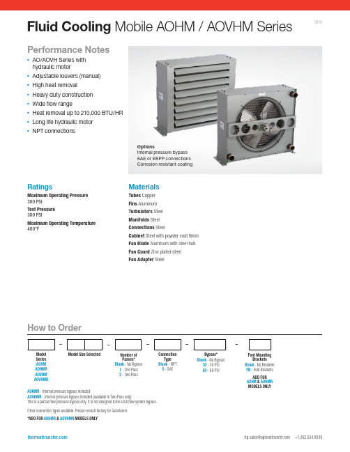
Fluid Cooling Mobile AOHM / AOVHM SeriesPerformance Notes▪AO/AOVH Series with hydraulic motor▪Adjustable louvers (manual) ▪High heat removal ▪Heavy duty construction ▪Wide flow range ▪ H eat removal up to 210,000 BTU/HR▪ L ong life hydraulic motor ▪NPT connections–ModelSeries AOHM AOHMR AOVHM AOVHMRModel Size Selected––Connection Type Blank - NPT S - SAEFoot Mounting Brackets Blank - No Brackets FB - Foot Brackets ADD FOR AOHM & AOHMR MODELS ONLY–Number of Passes*Blank - No Bypass 1 - One Pass 2 - Two PassBypass*Blank - No Bypass 30 - 30 PSI 60 - 60 PSIOther connection types available. Please consult factory for assistance.*ADD FOR AOHMR & AOVHMR MODELS ONLYAOHMR - Internal pressure bypass includedAOVHMR - Internal pressure bypass included (available in Two Pass only)This is a partial flow pressure bypass only. It is not designed to be a full flow system bypass.–OptionsInternal pressure bypass SAE or BSPP connections Corrosion resistant coatingMaterialsTubes Copper Fins Aluminum Turbulators Steel Manifolds S teel Connections S teelCabinet S teel with powder coat finish Fan Blade A luminum with steel hub Fan Guard Z inc plated steel Fan Adapter S teelRatingsMaximum Operating Pressure 300 PSI Test Pressure 300 PSIMaximum Operating Temperature 400°FHow to Order0916NOTE: We reserve the right to make reasonable design changes without notice. All dimensions are in inches.Fan Rotating Clockwise/Facing Motor ShaftAIR FLOW1.7510.361.62.56C A DEFKLB J1.13H G .756.312.314.629.2510.38M INLETM OUTLET.56 DIA.6 HOLES1/2-13 UNC-2B2 HOLES TOP , 2 HOLES BOTTOM (4 HOLES TOP , 4 HOLES BOTTOMAOHM 35 & 40)See dimensional chart for external NPT or optional internal SAE connection size.Foot Brackets: Optional for AOHM Standard with AOVHMDimensionsPerformance CurvesAOHM SeriesAOVHM SeriesOil Flow - GPMH e a t D i s s i p a t i o n B T U /H R a t 50°F E T D250,000200,000150,000100,000 90,000 80,000 70,000 60,000 50,000 40,000 30,000 25,000 20,000 15,00010,000 9,000 8,000 7,000Oil Flow - GPMH e a t D i s s i p a t i o n B T U /H R a t 50°F E T D100,00090,00080,00070,00060,00050,00040,00030,00025,00020,00015,00010,0009,0008,0007,0006,0005,0004,0003,000DimensionsPerformance Curves are based on 50 SSU oil entering the cooler 50°F higher than the ambient air temperature used for cooling. This is referred to as a 50°F ETDSTEP 1 D etermine the Heat Load. Heat load may be expressed as eitherhorsepower or BTU/HR To convert horsepower to BTU/HR: BTU/HR = Horsepower x 2545STEP 2 D etermine Entering Temperature Difference. The entering oiltemperature is generally the maximum desired oil temperature.Entering oil temperature – Ambient air temperature = ETDSTEP 3 D etermine the Corrected Heat Dissipation to use the curves.Corrected Heat Dissipation =BTU/HR heat load x 50°F ETDx viscosity correction A.STEP 4 E nter curves at oil flow through cooler and curve heat dissipation.Any curve above the intersecting point will work.N OTE: Performance curves shown are for 1 and 2 pass configuration.EXAMPLE: 35 - 2 is AOHM or AOVHM - 35 in 2 passSTEP 5 D etermine Oil Pressure Drop from Curves:l = 5 PSI n = 10 PSI s = 20 PSI Multiply pressure drop fromcurve by correction factor B found in oil viscosity correction curve.Desired Reservoir TemperatureOil Temperature: Oil coolers can be selected using entering or leaving oiltemperatures.Off-Line Recirculation Cooling Loop: Desired reservoir temperature is the oil temperature entering the cooler.Return Line Cooling: Desired reservoir temperature is the oil temperature leaving the cooler. In this case, the oil temperature change must be determined so that the actual oil entering temperature can be found. Calculate the oil temperature change (oil #T) with this formula: Oil #T = (BTU’s/HR) / (GPM Oil Flow x 210).To calculate the oil entering temperature to the cooler, use this formula: Oil Entering Temp. = Oil Leaving Temp + Oil #T.Oil Pressure Drop: Most systems can tolerate a pressure drop through the heat exchanger of 20 to 30 PSI. Excessive pressure drop should be avoided. Care should be taken to limit pressure drop to 5 PSI or less for case drain applications where high back pressure may damage the pump shaft seals.Oil TemperatureTypical operating temperature ranges are:Hydraulic Motor Oil 120°F - 180°F Hydrostatic Drive Oil 160°F - 180°F Engine Lube Oil 180°F - 200°F Automatic Transmission Fluid 200°F - 300°FHydraulic MotorOil Viscosity Correction MultipliersABV i s c o s i t y C o r r e c t i o nOil Viscosity SSU6 5 4 32.5 21.5150 60 65 70 75 80 90 100 200 300 400 500 600 700 800Notes: Maximum pressure is 2000 PSI. Stated minimum operating pressure is at inlet port of motor. 1000 PSI allowable back pressure.*Catalog db(A) sound levels are at seven (7) feet. dB(A) sound levels increase by six (6) dB(A) for halving this distance and decrease by (6) dB(A) for doubling this distance.Oil Viscosity Correction MultipliersAOHMR SeriesAOVHMR SeriesBypass valve is available for 2 pass AOVHMR models only.Two Pass (Low to Medium Oil Flows)Model Number Flow Range GPM (USA)AOVHMR - 5-2 4 - 50AOVHMR - 10-2 4 - 60AOVHMR - 15-2 4 - 60AOVHMR - 20-2 4 - 80AOVHMR - 25-2 4 - 80AOVHMR - 30-2 4 - 80AOVHMR - 35-2 6 - 80AOVHMR - 40-28 - 80One Pass (Medium to High Oil Flows)Model Number Flow Range GPM (USA)AOHMR - 5-1 2 - 80AOHMR - 10-1 3 - 80AOHMR - 15-1 4 - 80AOHMR - 20-1 5 - 80AOHMR - 25-1 6 - 100AOHMR - 30-17 - 100AOHMR - 35-18 - 112AOHMR - 40-19 - 118Two Pass (Low to Medium Oil Flows)Model Number Flow Range GPM (USA)AOHMR - 5-2 2 - 25AOHMR - 10-2 2 - 30AOHMR - 15-2 2 - 40AOHMR - 20-2 2 - 30AOHMR - 25-2 2 - 40AOHMR - 30-2 2 - 40AOHMR - 35-2 3 - 40AOHMR - 40-24 - 40Piping Diagram Without BypassOne PassTwo PassInternal Pressure Bypass。
Synflex 液体管道快速参考指南说明书
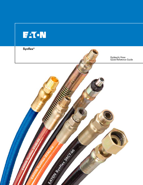
Zero scrap• F ormed assemblies arrive ready for installation.• N o custom bending or fitting is needed.Fewer leak points• F lexible hydraulic hosecan be formed in multipledimensions over the entirelength of a chassis.• W ith O-ring face seal fit-tings, assemblies are virtu-ally leak free.• T raditional failures atfatigue points with rigidtubing are eliminatedwith vibration-absorbingthermoplastic hose.Reduced assembly time• D rop-in assemblies savemore time than cus-tom formed tubing andmultiple adaptor setups.• F ormed assemblies makeJIT and line-sequencingefforts attainable, where-asbulk hose and tubing don’t.Reduced cost of pieceparts• O ften, when expensiveunions and adaptors arereplaced with continuoushose, the overall costis reduced.• MRO-friendly design.• W hen damaged,aftermarket assembliescan be easily replaced.• F lexible hose is easier toroute than formed tubing.Synflex®Formed HoseHydraulic EquipmentFork LiftConstructionApplications• Forklifts• Construction machinery• Material handlingequipment• Farm machinery• Mobile equipment BenefitsSynflex® formed hose is one of the most innovativeideas to come along in the past decade for hydraulichose applications. Utilizing the forming technologypioneered by Synflex, formed high pressurehydraulic hose is now available.Whatever your needs, our staff of professionals canaccommodate the products and services to guaranteeyour success.• 100R7• 3,000psi• -40 to 212˚F (-54 to 100˚C)• -03 to -08• Complies with ANSI A 92.2• G eneral hydraulics• A erial lift equipment• R ated “Non-Conductive”per ANSI Spec• U V stabilizers enhance thepolyurethane cover• G ood cold weather flexibility• F lexible, solid polyestercore tube• C ompatible with re-usablefittings3130• 100R1, 100R7• 2,250 - 3,500psi• -40 to 225˚F (-40 to 100˚C)• -04 to -12• E xceeds 100R7 specsand most competitivehose specs• M obile hydraulics• Lubrication systems• Agriculture equipment• P olyester core tube• G ood cold weather flexibility• H igh tensile, wire reinforcedand rugged design• C ut resistant• C rush resistant• B lack urethane jacket• H ighly UV resistant3580375037AL3740We carry a full lineof fittings....visit our website• 100R7• 1,000 - 3,000psi• -40 to 212˚F (-40 to 100˚C)• -02 to -16• G eneral hydraulics• Pneumatics• Agriculture equipment• Material handling• N ylon lined core tube• G ood chemical resistanceand low elongation• B lack urethane jacket• H ighly UV resistant• 100R7• 1,250 - 3,000psi• -40 to 212˚F (-40 to 100˚C)• -03 to -12• H ydraulic tools• Lubrication systems• Mobile hydraulics• Agriculture equipment• S tandard hose versionof 37AL• F lexible, solid polyestercore tube• C ompatible withre-usable fittings• U V resistant blackpolyurethane cover• G ood cold weather flexibility• 100R7• 1,000 - 3,000psi• -40 to 212˚F (-40 to 100˚C)• -03 to -16• G eneral hydraulics• A erial lift equipment• R ated “Non-Conductive”per SAE J517 Spec• N ylon lined core tube• U V resistant stabilizersenhance thepolyurethane cover• G ood cold weather flexibility• A vailable in sizes up to1” I.D.EATON Synflex Hose Quick Reference Guide E-HOOV-MR001-E August 20062• 100R8• 2,000 - 5,000psi• -40 to 212˚F (-40 to 100˚C)• -03 to -16• General hydraulics • A griculture • M aterial handling • F orestry • C onstruction • L ong life in impulse cycling and flexing applications• S olid nylon core tube • E xcellent chemical resistance • C ompatible with re-usable fittings • B lack urethane jacket • H ighly UV resistant • R ugged hose for demanding applications 3R80• 100R8• 3,500 - 6,000psi• -40 to 212˚F (-40 to 100˚C)• -02 to -08• P ilot lines • G eneral hydraulics • M achine tools • M obile equipment • A griculture equipment• N ylon lined core tube and aramid fiber reinforcement • H igh pressure hose with small O.D. to fit 100R7 fittings • L ow volumetric expansion3800• 100R8• 3,500 - 5,000psi• -40 to 212˚F (-40 to 100˚C)• -03 to -08• G eneral hydraulic system that may contact high voltage sources • M obile machinery • R escue tools • A erial equipment• N on-Conductive hose version of 3800• N ylon lined core tube • A ramid fiber reinforcement • L ow volumetric expansion • O range urethane jacket with UV stabilizers to enhance performance in outdoor applications • H igh pressure hose with small O.D. to fit 100R7 fittings• 100R8• 2,000 - 5,000psi• -40 to 212˚F (-40 to 100˚C)• -03 to -16• G eneral hydraulic system that may contact high voltage sources • M obile machinery • R escue tools • A erial equipment • R ugged hose for demanding applications• U V resistant stabilizers enhance the polyurethane cover • H igh pressure sizes available up to 1” I.D.• N on-Conductive hose version of 3R80 • S olid nylon core tube • E xcellent chemical resistance•I deal for use with re-usable fittings • O range urethane jacket 3E80• 100R18 • 3,000psi• -40 to 212˚F (-40 to 100˚C)• -03 to -16• F orklift • G eneral hydraulics • M aterial handling • F reezer application • P erfect for constant flexing applications• A nother 3000psi constant pressure hose available in larger I.D., sized up to 1” • N ylon lined core tube for chemical resistance and hytrel jacket for longer life in cold temperatures100R18• 100R18 • 3,000psi• -65 to 200˚F (-54 to 94˚C)• -03 to -10• F orklift • G eneral hydraulics • M aterial handling • F reezer application • P erfect for constant flexing applications•F lexible design with hytrel lined core tube and jacket to ensure flexibility and long life in temperature extremes • E ngineered for smaller O.D., yet keep 3000psi constant pressure rating• 8,000 - 10,000psi• -40 to 150˚F (-40 to 66˚C)• -03 to -06• R epair tools for highvoltage sources• R escue equipment andtools• M obile machinery• V ery high pressures• N on-Conductive hoseversion of 3V10• N ylon lined core tube• A ramid fiber reinforcement• O range urethane jacketwith UV stabilizers toenhance performance inoutdoor applications• 8,000 - 10,000psi• -40 to 150˚F (-40 to 66˚C)• -03 to -06• V ery high pressures• H ydraulic jacks• N ylon lined core tube forchemical resistance• A ramid fiber for lowvolumetric expansion andpressures up to 10,000psi• A full 4:1 safety factor atthese high pressure ratings• B lack urethane jacket forUV resistance and abrasionresistanceVery High Pressure HoseApplication Specific Hose• 1,500psi• -40 to 212˚F (-40 to 100˚C)• -04 to -08• L ow volumetric expansion• P ilot lines• I deally suited for controllines where responsive-ness is an issue• N ylon core tube provideschemical compatibility• U V resistant blackurethane jacket aids longlife in outdoor applications• C onstant pressure hoseline designed for lowervolumetric expansion31N0• 2,500psi• -65 to 200˚F (-54 to 93˚C)• -04 to -08• F orklift• G eneral hydraulics• M aterial handling• F reezer application• P erfect for constant flexingapplications• F lexible design with hytrellined core tube and jacketto ensure flexibility andlong life in temperatureextremes• E ngineered for smallerO.D pressure rating25CT• 100R3 performance• 1,000 - 1,750psi• -40 to 212˚F (-40 to 100˚C)• -03 to -08• W hen R7 pressures areoverkill and cost is an issue• Low pressure hydraulicequipment• Misting applications• General hydraulic andpneumatic• I dentical to 3130 family butwith lower pressure rating• H ighly UV resistant blackurethane cover• Nylon lined core tube3R30• 10,000psi• -40 to 212˚F (-40 to 100˚C)• -04 to -08• H igh pressureapplication• C ontrol valves• N ot for use with handheld applications• K evlar reinforcement forhigh pressures• 10,000psi hose with4:1 safety factor• S olid nylon core tube forexcellent chemicalresistance and tough UVresistant urethane sheathSpecification Applications FeaturesEATON Synflex Hose Quick Reference Guide E-HOOV-MR001-E August 20064Eaton14615 Lone Oak Road Eden Prairie, MN 55344 USATel: 952 937-9800 Fax: 952 974-7722 Eaton115 Lena Dr.Aurora, OH 44202USATel: 330 274-3171Toll Free: 800 837-1467Fax: 330 274-0473EatonGembloux S.A./N.V.Chaussee de Tirlemont, 100B-5030 GemblouxBelgiumTel: (32) 81-626-211Fax: (32) 81-615-789© 2006 Eaton CorporationAll Rights ReservedPrinted USADocument No. E-HOOV-MR001-EAugust 2006。
热流道使用及维护

处理:提高热喷嘴和分流板的温度,提高注塑压力,扩大浇口,提 高模温,安装大规格喷嘴,加大熔胶口出料口,清除堵塞物。
2008-3-28 / 12
© LKMHeatlock Co Ltd
7. 热喷嘴流延
使用方法: 1.生产完成时热流道需要清理; 2.停机或停机维修时流道要清理; 3.换色换料时也可清理流道;
2008-3-28 / 10
© LKMHeatlock Co Ltd
常见问题解答
1. 热分流板达不到设定的温度 原因:热电偶接触不良或失效,加热丝短路,加热丝接线太松或太短。 处理:检查热电偶接触是否正常,接线是否正确,检查发热丝回路。 2. 热分流板升温太慢
原因: 某一根加热丝断路或接线太松,热分流板空气空隙不足,隔热 垫片上过度冷却,热电偶接触不良。 处理:对所有加热丝进行检查,增加空气间隙,在定模固定板上增加 隔热板,或降低对定模板固定板的冷却,检查热电偶接触是否良好。 3. 热分流板温度不稳定 原因:热电偶接触不良。 处理:检查热电偶。
2008-3-28 / 11
9. 制品上有较多飞边
原因:注塑压力过高,温度过高,分模面平整质量差,锁模力不足,模具 底板或注塑机动模/定模板不平整。
2008-3-28 / 13
© LKMHeatlock Co Ltd
处理:降低注塑压力,降低热喷嘴/分流板/模具温度,增加锁模力,修 整模具,修整注塑机动模/定模板。 10. 制品上或浇口区域产生焦印,焦痕 原因:模具上排气不足,注射速度过快,浇口窝嘴尺寸不对,材料烘干 不够。 处理:增加排气,降低注射速度,增加浇口窝嘴的尺寸,烘干材料。 11. 注塑玻纤材料时嘴尖磨损太快 原因:嘴芯材料太软。 处理:换成LKMHEATLOCK生产的TZM合金嘴芯。 12. 浇口痕迹过大 原因:浇口过大,选用的热喷嘴类型不正确,浇口轮廓加工不正确。 处理:减小浇口,选择合适的热喷嘴类型,检查浇口加工轮廓。
君特热流道操作说明书DPK15-engl

GÜNTHER User Manual Hot Runner Systems DPK Hot Runner Systems Table of Contents:Page1GENERAL______________________________________________________________________1-4 2DISPLAY AND OPERATING CONTROLS__________________________________________2-6 2.1C ONTROL P ANEL________________________________________________________2-6 2.2P ARALLEL D ISPLAY______________________________________________________2-7 3OPERATING INSTRUCTIONS____________________________________________________3-8 3.1T URNING O N____________________________________________________________3-8 3.2M ULTI-C HANNEL M ODE__________________________________________________3-8 3.3S INGLE C HANNEL M ODE__________________________________________________3-9 3.4O PERATING M ODE______________________________________________________3-103.4.1 Changing Set Values_________________________________________________________________3-103.4.2 Switching Hot Runners On and Off_____________________________________________________3-113.4.3 Changing the Operating Mode …Thermocouple/Percentage“________________________________3-123.4.4 Temperature Lowering / Rising________________________________________________________3-13 3.5M ENU M ODE__________________________________________________________3-143.5.1 Set All Channels____________________________________________________________________3-163.5.2 Temperature Program_______________________________________________________________3-163.5.3 Temperature Lowering/Rising_________________________________________________________3-173.5.4 Serial Interface_____________________________________________________________________3-173.5.5 Power Monitor______________________________________________________________________3-173.5.6 Turn On Time______________________________________________________________________3-183.5.7 Configuration_______________________________________________________________________3-183.5.8 Heater 5V/24V______________________________________________________________________3-183.5.9 Language__________________________________________________________________________3-183.5.10 Service___________________________________________________________________________3-18 3.6C ONFIGURATION M ENU__________________________________________________3-193.6.1 Softstart___________________________________________________________________________3-193.6.2 Load Defaults_______________________________________________________________________3-203.6.3 Calibration_________________________________________________________________________3-213.6.4 PID - Parameter____________________________________________________________________3-213.6.5 Switching °C / F_____________________________________________________________________3-223.6.6 Temperature Window________________________________________________________________3-22 4OTHER FUNCTIONS___________________________________________________________4-234.1R EADY TO S TART M OLDING______________________________________________4-23 4.2E RROR M ESSAGES______________________________________________________4-23 4.3S TARTING R AMP_______________________________________________________4-27 5SERIAL INTERFACE___________________________________________________________5-285.1G ENERAL I NFORMATION_________________________________________________5-28 5.2T ROUBLE S HOOTING____________________________________________________5-29Table of Contents:Page6INSTALLATION AND START-UP________________________________________________6-30 6.1I NSTALLATION_________________________________________________________6-306.1.1 Location___________________________________________________________________________6-306.1.2 Electrical Connections_______________________________________________________________6-306.1.3 Additional Interfaces_________________________________________________________________6-32 6.2I NITIAL S TART-U P______________________________________________________6-356.2.1 Testing Thermocouple Connections_____________________________________________________6-356.2.2 Testing Heater Disconnections_________________________________________________________6-356.2.3 Testing Thermocouple and Load Crosswiring____________________________________________6-356.2.4 Aditional Information:_______________________________________________________________6-36 6.3I NSTALLING NEW S OFTWARE-EPROM´S____________________________________6-36 7APPENDIX____________________________________________________________________7-377.1A PPENDIX A – C ONNECTIONS TO THE DPK__________________________________7-37 7.2A PPENDIX B - F USES____________________________________________________7-39 7.3A PPENDIX C – S TAR-/D ELTA O PPERATION__________________________________7-41 7.4A PPENDIX D – T ECHNICAL D ATA__________________________________________7-42 7.5A PPENDIX E - S ERVICE F ORM_____________________________________________7-45 7.6A PPENDIX F – S CHEMATIC_______________________________________________7-46 7.7A PPENDIX G – P OSITION S CHEMATIC_______________________________________7-47 7.8A PPENDIX H - A DDRESSES________________________________________________7-48 7.9A PPENDIX I – EG D ECLARATION OF C ONFORMITY____________________________7-51GÜNTHER User Manual Hot Runner Systems DPK Hot Runner Systems Warranty Condtions:1.Installation and implementation must be carried out by an electrician!2.Please refer to chapter 6 - Installation and Inplementation of the DPK usermanual prior to the installion of the device!3.Before connecting the device to the main power supply, check the mainvoltage and the type of net (star or delta)!1GeneralThe hot runner system DPK has been built and tested according to DIN 57411 part 1 and VDE 0411 part 1 (Germany). It has left the factory in perfect condition. In order to keep your product fully operational and to guarantee safe operation, please read this instruction manual carefully and follow all hints. Before switching on, it is important to check that the local voltage is identical to that allowed by the unit. The plug may only be plugged into to an earthed socket. Any disconnection of the earth cable (e.g. an extension of the cable without earth connected) can cause hazardous conditions to the unit.Hint:Disconnect mains before opening unit. Refer to a qualified technician for servicing.The DPK unit is an optimized hot runner control unit, it is more efficient and reduces costs.Advantages for the user:•Available in 5, 10, or 15 hot runner versions according to the user’s requirements.•The DPK automatically recognizes low voltage nozzles and 230V hot runner elements and sets its control parameters accordingly.•Only one unit is required for mixed operation .•PID controller with variable parameters, fast heating of 5V and 24V low voltage nozzles, careful heating of 230V hot runner elements.•Control operation is possible at all times even in the event of thermocouple failure.•Existing power units from the 160 series can continue to be used as the DPK control unit is compatible with all existing GÜNTHER power units.•Because of the module construction, system upgrades are possible.The DPK is reliable and safe, due to continuous checking and monitoring functions.Advantages for the user:•Continuous self-monitoring function.•Protects low voltage nozzles from current overload.•Identifies thermocouple failures, heat circuit disconnections and short circuits.•Turns off the power supply in case of a malfunction and signals the alarm via a potential free contact.•Parameters and programs are saved in an EPROM and are therefore not lost in the case of a power supply failure.The DPK is designed for easy use, this makes installation and tool change simple.Advantages for the user:•The DPK is especially designed for simple and easy operation.•The multi-function keypad has an easy to use layout and because of its dust and water proof key pad, it withstands tough environments.•The simple operator entry levels prevents wrong operation.•All hot runners are simultaneously displayed and for each hot runner the set and actual values.•The control parameters are adjustable according to the application.•The implemented diagnostic tests the complete system, including tools, nozzles, distributors and the hot runner system for malfunction.•Incorrectly connected circuits are located before start of operation.•Low installation cost due to combined thermal and power connections.The DPK has numerous special functions for optimal system utilizationAdvantages for the user:•Power output surveillance is possible during operation.•Decrease and increase temperature for all control points by simply pressing a key.•Reading of the effective current at low voltage.•Several set value programs simplify material or tool change.•If desired, a serial interface is available as connection to the injection molding machines.GÜNTHER User Manual Hot Runner Systems DPK Hot Runner Systems 2Display and Operating ControlsThe display and operating controls of the DPK are located on the operation control panel and the parallel display. Great emphasis has been placed upon ease of use and a good layout.2.1Control Panel ArrayFunction KeysA Key …°C/F↓“>lowering temperature all zonesB Key …°C/F↑“>raising temperature all zonesC Key …MENU“>show menuE – H Keys …!“, …"“, …#“, …$“>changing & adjusting set values and parameters,cancel functionD Key …ENTER“>´ENTER KEY´ to confirm inputs,to quit program levelsHint:For further details concerning keys and their functions see chapter 3.3 Operation.2.2Parallel DisplayThe parallel display is a 15-fold 3-digit seven segment display for set temperature, actual temperature, temperature difference or actual adjustable variables in ´%´. Three additional LEDs are located beside each indicator to display the status of the zone.If a channel is turned off, " --- " appears in the accompanying display. The percent control variable is displayed to channels which work in the setting mode.Between the operating controls and parallel display the “#“ key and 4 LED´s are placed. The key is used to display the set value, actual value, temperature difference or the display of current in …%“. The LEDs above the key shows the selected display type.The temperature state in addition is one by one displayed for every channel. If the green indicator shines behind the corresponding value, this channel has reached the programed temperature window (ready for molding). There is an over and under indicator also which is a red indicator for both conditions.GÜNTHER User Manual Hot Runner Systems DPK Hot Runner Systems 3 Operating Instructions3.1 Turning OnAfter the unit has been switched on the Günther logo, the program revision number and the serial Number will be shown on the display. Then the unit automatically performs a system check which includes the heating circuits, whether a low voltage or a 230 volt load is connected. After the system check the DPK detects the load if it is a low voltage or 230 V .The Display will show a table of all loads. If faults are detected on the system or the loads (nozzles, distributor or cables) the fault is displayed and the loads are switched off. At the same time the parallel display shows TST (Test)and then the detected voltage of the load. If a load turned of in reasen of a fault, or if it is not connected, the parallel Display will be shown …---“.3.2 Multi-Channel ModeAfter the adjusting of the loads has been performed, the controller is in the multi-channel mode. In this mode every five channels are display for a short time interval.The set value and the current value in degrees celsius or degrees fahrenheit is displayed in this mode. The control value is also displayed in per cent (%) for 230V nozzles or in ampere (A) for 24V or 5V nozzles.230V loads pass through a so-called softstart if the set temperature is higher than 105°C (221°F). If the softstart is active, all 230V loads are clamped to 105°C. This clamping ends if all loads have reached this temperature (see chapter 3.6.1 Softstart ).Hint:At the apperance of any failure the multi-channel mode will be interupted and the failure will be visualized on the display. If several errors occur, then the channel whose error was recognized first is displayed. This is also valid if the display is switched from the menu mode to the multi-channel mode after the apperance of any failure.Fig. 3-1 Multi-Channel Mode3.3 Single Channel ModeTo change from the multi-channel mode to the single-channel, mark a channel with the keys marked …#“ or …$“. By pressing the keys …"“ or …Enter“ the channel is entered in single-channel mode.The single-channel mode is now shown on the display. In this mode all data (rated value, actual value, load caracter, current, power consumption) of each channel will be shown.At first, in the single-channel mode, the channel number is marked. By pressing the key …!“the display mode returns to the multi-channel mode.Towards a cycle of 2 seconds the mark switched off, now it is possible by pressing the key …!“ to turn the display mode to the scan mode.The following sign indicates the scan mode.In this mode the zones with set and actual values will be displayed in the display, one by one.Runners wich are switched of will be skipped.The unit (%,A,°C,°F) for each zone number, will be displayed at the same time.The scan mode ca be cancelled by pressing any key and restarted by pressing the …!“ key after 2seconds when the mark of the channel nummber swiched off again.Hint:If a fault occurs, the scan mode will be terminated and channel number causing a fault will be shown on the display. If several faults occur at the same time, the zone where the first fault occured is displayed.Fig. 3-1 Single channel ModeGÜNTHER User Manual Hot Runner Systems DPK Hot Runner Systems 3.4Operating Mode3.4.1Changing Set ValuesDuring the single-channel mode move the mark to the set value, by pressing the …"“ key. The desired set value is entered by pressing the key …#“ and …$“. The key function is dynamic i.e. the longer the key is pressed, the quicker the set point value changes.The controller operation works independently from the entering of a value. It is therefore not necessary to return to the scan mode. Scan mode makes exact surveillance of critical regulation positions possible.Value limits:The temperatures are adjustable within a range from 0 to 500 °C(0 to 932 °F).The percentage control mode is adjustable from 0% to 100%.3.4.2Switching Hot Runners On and OffIf a hot runner is unused, it is posible to switch it off.Fig. 3-1 Switching Hot Runners On and OffDuring the single-channel mode move the mark to the ON/OFF button by pressing the …"“ key. Now the setting may be changed by pressing the …#“ or …$“ key.Runners which are switched off will be displayed only in the multi-channel mode and are not checked for faults anymore.GÜNTHERUser Manual Hot Runner Systems DPK Hot Runner Systems3.4.3 Changing the Operating Mode …Thermocouple/Percentage“In the event that a thermocouple fails to function, or for any other reason, the percentage control mode can be carried out to continue the control operation manually. The current will then be displayed in percent (%).Mark the menu item power or temp. in single-channel mode by pressing the …"“ key, choose between thermocouple or percentage by pressing the …#“ or …$“ key.For low voltage-nozzles it will be:100% approximately 125A (for 5V nozzles)100% approximately 25A (for 24V nozzles)Fig. 3-1 Changing the Operating Mode3.4.4Temperature Lowering / RisingIf production stops for a longer period of time, it is advisable to lower the set temperatures without turning the unit off.By pressing the key …°C/F↓“ lowering temperature is activated. The display shows in the multi-channel mode at the left corner …t-lowering“, in the single-channel mode the following sign.An external activation of the temperature lowering is possible by connecting a closing contact at the rear side of the DPK. It is possible to connect a potential free contact to the unit with a cable which is available from GÜNTHER HOT RUNNER SYSTEMS (specially for relay output of injection molding machines).Additionally it is possible to increase the temperature for all runners at the same time. By pressing the key …°C/F↑“ the temperature rise is activated. The display shows in the multi-channel mode at the left corner …t-boost“, in the single-channel mode the following sign.The temperature lowering mode is cancelled by pressing the key …°C/F↓“ once more. Now the old set values are valid. The lowering value may be adjusted by the menu temp. lowering (in °C/°F, 0 -255). The rise temperature mode is cancelled by pressing the key …°C/F↑“. The rising value may be adjusted by the menu temp. boost. If the lowering or rising is cancelled, the old set values are restored.GÜNTHERUser Manual Hot Runner Systems DPK Hot Runner Systems3.5 Menu ModeBy pressing the …menu“ key the menu mode is activated. The main menu will be shown on the display.Use the …#“ und …$“ keys to select and the A or …ENTER“ key to confirm a menu item. If the operater does not makes modifications in the main or in a other menu the display mode will be changed after a time of 10 seconds and the display will show the single- or multi-channel mode.If a menu item is confirmed, the value may be changed by pressing the …#“ and …$“ keys. By pressing the …!“ oder …ENTER“ key you will return to the menu. If the …ENTER“ key is used the displayed value will be stored as a new set value. By using the …!“ key the value will not be stored (cancel function).The menu structure is on the next page.Fig. 3-1 Main MenuMenustructure of the DPKFig. 3-2 Menu structure of the DPKGÜNTHER User Manual Hot Runner Systems DPK Hot Runner Systems 3.5.1Set All ChannelsThe menu …set all channels“ enables the operator to change the temperature, the controller output or to turn on or off all channelFig. 3-1 Changing Temperature Program3.5.3 Temperature Lowering/RisingBy the two menus …temp. lowering“ and …temp. boost“ the operator could set the increase or decrease temperature. By using the …°C/F↓“ key the temperature drops about the value which adjusted in the menu …temp. lowering“. By using the …°C/F↑“ key the temperature rises about the value which adjusted in the menu …temp. boost“.3.5.4 Serial InterfaceThe DPK is generally delivered with one serial interface …COM1“. This interface is a standard RS 232 interface. The serial interface …COM1“ is only to connect a DPK to a personal computer or to comunicate with other DPK.An optional serial interface …COM2“ for injection molding machines is available. An add on Kit for delivered units is also available. With the interface …COM2“ it is possible to remote control and display the information of the DPK unit via the injection moulding machine. The interface enables easy quality control because of the possible production data acquisition.Because each injection moulding machine producer has ist own communication protocol, use the menu item …molding machine“ to select the protocol of the molding machineYou can see which interface is needed by reading the user manual of the molding machine or contact Günther Hot Runner Systems for further information.In the menu are the items Arburg, Engel und Kraus Maffei (see Chapter 5 Interface).3.5.5 Power MonitorThe menu power monitor will show the total power consumption and the current separated for each line at the moment.Fig. 3-1 Power MonitorGÜNTHER User Manual Hot Runner Systems DPK Hot Runner Systems 3.5.6Turn On TimeThe hours of operation are displayed in the menu turn on time. Every time when the DPK is switched on this time is incremented.3.5.7 ConfigurationBy choosing the menu item configuration the configuration menu will be entered. You need a password to enter this menu. In the configuration menu the operater can change the language, the PID parameter or calibrate the DPK etc.For further information refer to Chapter 3.6 Configurationmenu.3.5.8 Heater 5V/24VIn this menu item the type of the low voltage load (5V/24V) for all channels can be set. This means the DPK is able to work in a mixed mode with 230V and 5V nozzles or in a mixed mode with 230V and 24V nozzles. A mixed mode for 5V and 24V nozzles is not supported!3.5.9 LanguageIn this menu item you are able to change the language for the display and the menu. The DPK supports three languages: german, english and french.3.5.10ServiceThis menu item is used by the manufacturer of the DPK for several setting. This menu has ist own password. The user must not and need not make any changes to this menu.3.6Configuration MenuBy scrolling through the main menu, the configuration menu can be entered. A password is needed to enter this menu. In the configuration menu the operater can change the PID parameter or calibrate the DPK etc.The password for the configuratin menu is: 0099The entered password is only valid for 15 minutes or up to the moment where the DPK is turned off. For further changes to the configuration you need to enter it again.Fig. 3-1 Configuration3.6.1SoftstartWhen 230V nozzles are used it is necessary to employ the softstart start-up procedure to dry out the moisture that has collected in the heating elements. In order to do this, in the first phase of the softstart (the set time) value of the menu softstart is increased from 0 to 50% . The ramp time should be selected in such a manner, that the DPK reaches the temperature of 105°C at the end of the ramp. If the temperature is less than 105°C at the end of the ramp, the DPK will increase the temperature to 105°C. After the DPK has reached the 105°C the second time controlled phase of the softstart (the holdtime) begins. The ramp and the hold time is adjustable by the menu softstart and could be changed in 2 seconds steps. The holdtime is used to adequately dry out the nozzle with a low thermic load. This start-up operation will begin automatically if it´s been activated in the softstart menu after the control unit or runner is switched on and also after a program change. The softstart start-up procedure is activated individually and automatically for each zone when the actual temperature of a 230V nozzle remains below 100°C, because the set value is programmed over 100°C. The softstart is indicated in the single channel mode by the following sign.ramp time hold timeIn the multi channel mode by the text …softstart“ and the countdown in the left corner.After the end of the holdtime the unit will switch from softstart to normal operating mode. To prevent overheating of the molding material in the 5V nozzles during combined operations employing both 5V and 230V nozzles, the 5V nozzles are limited to temperatures not exceeding 105°C during softstart. The temperature lowering is taken into consideration during softstarts, so that the DPK unit can begin to operate immediately with an instant temperature lowering.GÜNTHER User Manual Hot Runner Systems DPK Hot Runner Systems3.6.2 Load DefaultsBy selecting the menu item load defaults and affirming the questions with yes twice, the DPK loads up the parameters and values to the factory settings.Attention!All individual entered settings of the DPK (values and parameters) will be deleted!The following table shows the default settings:Set All Channels:100°C(all set temperatures)Temperature Programs: 1. power ON50%2. power OFF75%3. temp.ON100°C4. temp.OFF200°CSoftstart:ONover all time:10minhold time:5minramp time:5minPID-Parameter:P-Value:60(for all channels)I- Value:60D- Value:30Temperature Unit:°CTemperature Window:+/- 5°CLowering Value:50°CRising Value:50°CLanguage:GermanInterface:ArburgHeater 5V/24V:24V3.6.3CalibrationThe sophisticated and microcontroller seconded temperature module of the DPK could calibrate its self by using a calibrationjack.Fig. 3-1 CalibrationThe calibriation jack is available from GÜNTHER HOT RUNNER SYSTEMS, without the jack the error message of Fig. C will be shown on the display.3.6.4 PID - ParameterThe operater can change the PID parameter using the menu item …pid-parameter“. So the operator is able to match the parameter to the controlled system. It is possible to match the paramters independently.GÜNTHERUser Manual Hot Runner Systems DPK Hot Runner Systems3.6.5 Switching °C / FBy choosing the menu item …switch °C/F“ it is possible to choose between degrees celsius or fahrenheit.3.6.6 Temperature WindowThe width of the windows for the value of the existing temperature can be changed in the menu item temperature window. Is the value of the temperature at the nozzle within this window, this will cause the lightning of the O.K. indicator in the parallel display. If all temperatures are in within the window, the ready to mold output will be set.Fig. 3-1 Switching °C/°F4Other Functions4.1Ready to Start MoldingAs soon as the adjusted runners have reached the preset temperatures the OK LED is switched on and in the bottom line of the display appears the text …ready for molding“. Additionally a potential free relay contact is switch on. This relay contact is located on the rear side of the system and is marked with OK.The OK LED and the relay output will be switched off in case of:• a fault•lowering4.2Error MessagesIn the event of a fault, the display will show the fault and the protection system will shut down the power. With this fault the relay contact is switched. By pressing the …ENTER“ key the faulty channel will be switched off and the other channels will be switched on.During the hot runner test all channels without a fault switched on and so it is not a mistake it is only a warning that the faulty channel is switched off.A channel which evoked a warning is switched in the off temperature mode when no load is detected and switched in the off percentage mode when no thermocouple is detected.The following faults are possible.The thermocouple of the shown channel was notfound. Please check the thermocouple and its` wires.Fig. 4-1 Thermocouple FailureGÜNTHER User Manual Hot Runner Systems DPK Hot Runner SystemsThermocouple ExchangeThe thermocouple of the shown channel is notconnected right. The + and – connections areexchanged. Please change the direction of theconnections.Thermocouple ShortcutThere is a short circuit at the thermocouple or itsconnections at the shown channel. Please check thethermocouple and its` wires.Over TemperatureThe thermocouple of the shown channel detects atemperature above 500°C. Please check thisthermocouple and its` wires. You should also checkthe thermocouples for neighboring nozzles.Fig. 4-2 Thermocouple ExchangeFig. 4-3 Thermocouple ShortcutFig. 4-4 Over TemperatureCheck Thermo-connectorThe connector of the thermocouple at the shownchannel is missing or is not fixed. Please check theconnections.Load InterruptedThe wires to the power module or to the nozzle ofthe shown channel are interrupted. Please check theload fuses and the wires.In normal operation the load interruption is onlydetected at a percetage value of 100%. This errormessage can occup at the adjustage. In this case,the power of the nozzle could be to small for thisapplication.Load Connector FailureThe load connector is lost or not fixed. Pleasecheck the connector.Fig. 4-5 Check Thermo-connectorFig. 4-6 Load InterruptedFig. 4-7 Load Connector Failure。
创新流动能量 ELH 系列 - 流动冷却器说明书
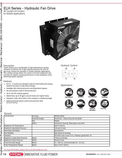
IndustrialRailwaysAgriculturalConstructionUtilityMaterialHandlingForestryOffshoreELH Series - Hydraulic Fan DriveAir Cooled Oil Coolers for Mobile ApplicationsDescriptionThese coolers use a combination of high performance cooling elements combined with a high capacity hydraulic fan drive to give long, trouble free operation in mobile hydraulic applications. The compact design allows the coolers to fit most equipment and provides the highest cooling performance in heat dissipation while minimizing space required.Features• E LH 2 - 5 coolers are designed with the inlet/outlet ports facing towards the back to help reduce fittings • Available with internal pressure and temperature bypass • All units feature a built in thermostat port • Up to 180 HP cooling capacity• Rated flows up to 90 gpm (consult factory for higher flows)• H ydraulic motor drive offers more cooling in a smaller package • O ptional thermal speed control and pressure relief(Consult Factory)Hydraulic SymbolApplicationsGeneralConstructionHousing Welded SteelHeat Exchanger Aluminum - Heavy Duty bar and plate Fan PlasticMotorAluminum housing, Steel gears and shaft Maximum Oil Temperature 266ºF (130ºC)Maximum Operating Pressure 230 psi (16 bar)Mounting Orientation All positionsFan Rotation See arrow on housingFiltrationISO/DIS 4406 Code 19/16- Filtration grade B25>75Maximum Outlet Side Pressure Motor 1740 psi (120 bar)Maximum Drain Pressure Motor 29 psi (2 bar)Fluid Viscosity Range Motor 10 - 600 cst. (recommended 30 - 45 cst.)Fluid Temperature RangeMotorUp to 194˚ F (90ºC)t e s y o f C M A /F l o d y n e /H y d r a d y n e ▪ M o t i o n C o n t r o l ▪ H y d r a u l i c ▪ P n e u m a t i c ▪ E l e c t r i c a l ▪ M e c h a n i c a l ▪ (800) 426-5480 ▪ w w w .c m a f h .c o mModel CodeELH 2 1.5 H6.3 S IBT 45 - 2 ModelELH = Air Cooled Oil Cooler with Hydraulic Fan DriveSize(See the heat transfer table found on page 16 to determine the proper size.)234567891011Modification Number (latest version always supplied)Hydraulic Motor Drive DisplacementH6.3 = 6.3 ccm/rev (available only on ELH 2-6 and ELH 8)H14 = 14 ccm/revH22 = 22 ccm/revAir Flow DirectionS = Suction (standard)B = BlowingAccessoriesF = Optional foot mount (sizes 2 - 4 only)IBT = thermostatic bypass valveIBP = integrated pressure bypass valveOpening Temperature (IBT only)Opening Temp. Closing Temp.45 = 113°F (45°C) 131°F (55°C)50 = 130°F (55°C) 150°F (65°C)60 = 140°F (60°C) 158°F (70°C)Opening Pressure Drop (IBT & IBP only)2 = 2 bar (29 psi)3 = 3 bar (45 psi)4 = 4 bar (58psi) (IBP only)CMA/Flodyne/Hydradyne▪MotionControl▪Hydraulic▪Pneumatic▪Electrical▪Mechanical▪(8)426-548▪www.cmafh.co mPressure Drop @ 30cSt(tolerance ± 5%)Pressure differential ∆p depending on flow rate Q and the viscosity of the oil.ELH SeriesHeat Dissipation @∆T =72ºF(tolerance ± 5%)Cooling capacity depends on oil flow and the temperature differential (∆T) between the oil inlet and air inlet.Sizes 6 - 11Sizes 2 - 5ELH-3ELH-5ELH-2ELH-4ELH-6ELH-7ELH-8ELH-9ELH-10ELH-11454035302520151050051015202530354045505560657075808551015202530354045505560657075808590510152025303540455055606570Oil Flow [GPM]Oil Flow [GPM]Oil Flow [GPM]P r e s s u r e D r o p [P S I ]2252001751501251007550250H e a t D i s s i p a t i o n [H P ]ELH-4 3000 RPMELH-5 2000 RPM ELH-4 1500 RPM ELH-2 1500 RPMELH-2 3000 RPM ELH-3 3000 RPMELH-3 1500 RPMELH-5 3000 RPMH e a t D i s s i p a t i o n [H P ]45504035302520151050• For other viscosities, the result must be multiplied by the K factors belowC M A /F l o d y n e /H y d r a d y n e ▪ M o t i o n C o n t r o l ▪ H y d r a u l i c ▪ P n e u m a t i c ▪ E l e c t r i c a l ▪ M e c h a n i c a l ▪ (800) 426-5480 ▪ w w w .c m a f h .c o mELH SeriesDimensions Sizes 2 - 4Size 5(6X)Dimensions are for general information only, all critical dimensions should be verified by requesting a certified print. Dimensions are in inches.t e s y o f C M A /F l o d y n e /H y d r a d y n e ▪ M o t i o n C o n t r o l ▪ H y d r a u l i c ▪ P n e u m a t i c ▪ E l e c t r i c a l ▪ M e c h a n i c a l ▪ (800) 426-5480 ▪ w w w .c m a f h .c o mELH SeriesDimensions Sizes 6Sizes 7 - 8Dimensions are for general information only, all critical dimensions should be verified by requesting a certified print. Dimensions are in inches.t e s y o H y d r a d y n e ▪ M o t i o n C o n t r o l ▪ H y d r a u l i c ▪ P n e u t r i c a l ▪ M e c h a n i c a l ▪ (800) 426-5480 ▪ w w w .c m a f h .c o mELH SeriesDimensions Sizes 9 - 11ELH Series 2-4 Mounting Foot BracketDimensions1.97”50mm1.42”36mm0.71”18mm4mmDimensions are for general information only, all critical dimensions should be verified by requesting a certified print. Dimensions are in inches/mm.t e s y o f C M A /F l o d y n e /H y d r a d y n e ▪ M o t i o n C o n t r o l ▪ H y d r a u l i c ▪ P n e u m a t i c ▪ E l e c t r i c a l ▪ M e c h a n i c a l ▪ (800) 426-5480 ▪ w w w .c m a f h .c o m。
热流道温度控制卡操作说明书

产品说明
本控制器是以微电脑控制的HOT-Runner”(热流道)系统控制模组为架构,提供温
度控制与操作界面程式,控制一个温度区域是藉由一个J或K型热电偶型感测器的检测。
本控制器操作界面输入是经由一组4个按键输入,显示是经由两组LCD的七段显示 器,前一组显示为三个文字显示器(显示实际温度),后一组是4个文字显示器(显示温
度设定值),另外还有三个分离型LED指示灯,显示系统运转模式。
本控制器是由控制板及显示板组成的控制系统,一个是主控制板,另一个是操作面 板,它可以完全的相容并存在于其它品牌的热流道模温控制系统上。
本控制器适用于工业环境中,操作简单方便。
Tan Rex
热流道温度控制卡
操技
TanRex系列简介
感谢您选购本公司Tan Rex系列高品质的温控器。本控制器具有如下特点:
1、在现有的热流道控制系统相容性上可容易达到维修与互换。
2、可同时显示温度设定点与温度实际值,以及温度输出功率、百分比和电流值。
3、内建分析操作情况,错误时出现错误显示,以方便维修。
威尔恩工程有限公司产品说明书
©2002 Whelen Engineering Company Inc.Form No.13721B (072105)For warranty information regarding this product, visit /warrantyA u t o m o t i v e : •Proper installation of this product requires the installer to have a good understanding of automotive electronics, systems and procedures.•Whelen Engineering requires the use of waterproof butt splices and/or connectors if that connector could be exposed to moisture.•Any holes, either created or utilized by this product, should be made both air- and watertight using a sealant recommended by your vehicle manufacturer.•Failure to use specified installation parts and/or hardware will void the product warranty.•If mounting this product requires drilling holes, the installer MUST be sure that no vehicle components or other vital parts could be damaged by the drilling process. Check both sides of the mounting surface before drilling begins. Also de-burr the holes and remove any metal shards or remnants. Install grommets into all wire passage holes.•If this manual states that this product may be mounted with suction cups, magnets, tape or Velcro®, clean the mounting surface with a 50/50 mix of isopropyl alcohol and water and dry thoroughly.•Do not install this product or route any wires in the deployment area of your air bag. Equipment mounted or located in the air bag deployment area will damage or reduce the effectiveness of the air bag, or become a projectile that could cause serious personal injury or death. Refer to your vehicle owner’s manual for the air bag deployment area. The User/Installer assumes full responsibility to determine proper mounting location, based on providing ultimate safety to all passengers inside the vehicle.•For this product to operate at optimum efficiency, a good electrical connection to chassis ground must be made. The recommendedprocedure requires the product ground wire to be connected directly to the NEGATIVE (-) battery post (this does not include products that use cigar power cords).•If this product uses a remote device for activation or control, make sure that this device is located in an area that allows both the vehicle and the device to be operated safely in any driving condition.•Do not attempt to activate or control this device in a hazardous driving situation.•It is recommended that these instructions be stored in a safe place and referred to when performing maintenance and/or reinstallation of this product.•FAILURE TO FOLLOW THESE SAFETY PRECAUTIONS AND INSTRUCTIONS COULD RESULT IN DAMAGE TO THE PRODUCT OR VEHICLE AND/OR SERIOUS INJURY TO YOU AND YOUR PASSENGERS!Warnings to InstallersWhelen’s emergency vehicle warning devices must be properly mounted and wired in order to be effective and safe. Read and follow all of Whelen’s written instructions when installing or using this device. Emergency vehicles are often operated under high speed stressful conditions which must be accounted for when installing all emergency warning devices. Controls should be placed within convenient reach of the operator so that they can operate the system without taking their eyes off the roadway. Emergency warning devices can require high electrical voltages and/or currents. Properly protect and use caution around live electrical connections.Grounding or shorting of electrical connections can cause high current arcing, which can cause personal injury and/or vehicle damage, including fire. Many electronic devices used in emergency vehicles can create or be affected by electromagnetic interference. Therefore, after installation of any electronic device it is necessary to test all electronic equipment simultaneously to insure that they operate free of interference from other components within the vehicle. Never power emergency warning equipment from the same circuit or share the same grounding circuit with radio communication equipment. All devices should be mounted in accordance with the manufacturer’s instructions and securely fastened to vehicle elements of sufficient strength to withstand the forces applied to the device. Driver and/or passenger air bags (SRS) will affect the way equipment should be mounted. This device should be mounted by permanent installation and within the zones specified by the vehicle manufacturer, if any. Any device mounted in the deployment area of an air bag will damage or reduce the effectiveness of the air bag and may damage or dislodge the device. Installer must be sure that this device, its mounting hardware and electrical supply wiring does not interfere with the air bag or the SRS wiring or sensors. Mounting the unit inside the vehicle by a method other than permanent installation is not recommended as unit may become dislodged during swerving; sudden braking or collision. Failure to follow instructions can result in personal injury. Whelen assumes no liability for any loss resulting from the use of this warning device. PROPER INSTALLATION COMBINED WITH OPERATOR TRAINING IN THE PROPER USE OF EMERGENCY WARNING DEVICES IS ESSENTIAL TO INSURE THE SAFETY OF EMERGENCY PERSONNEL AND THE PUBLIC.Warnings to UsersWhelen’s emergency vehicle warning devices are intended to alert other operators and pedestrians to the presence and operation of emergency vehicles and personnel. However, the use of this or any other Whelen emergency warning device does not guarantee that you will have the right-of-way or that other drivers and pedestrians will properly heed an emergency warning signal. Never assume you have the right-of-way. It is your responsibility to proceed safely before entering an intersection, driving against traffic, responding at a high rate of speed, or walking on or around traffic lanes. Emergency vehicle warning devices should be tested on a daily basis to ensure that they operate properly. When in actual use, the operator must ensure that both visual and audible warnings are not blocked by vehicle components (i.e.: open trunks or compartment doors), people, vehicles, or other obstructions. It is the user’s responsibility to understand and obey all laws regarding emergency warning devices. The user should be familiar with all applicable laws and regulations prior to the use of any emergency vehicle warning device. Whelen’s audible warning devices are designed to project sound in a forward direction away from the vehicle occupants. However, because sustained periodic exposure to loud sounds can cause hearing loss, all audible warning devices should be installed and operated in accordance with the standards established by the National Fire Protection Association.Safety FirstThis document provides all the necessary information to allow your Whelen product to be properly and safely installed. Before beginning the installation and/or operation of your new product, the installation technician and operator must read this manual completely. Important information is contained herein that could prevent serious injury or damage.Installation Guide Model IBF5150Brake/Back-up Light Flasherfor Dodge Intrepid51 Winthrop RoadChester, Connecticut 06412-0684Phone: (860) 526-9504Internet: Salese-mail:*******************CustomerServicee-mail:*******************®ENGINEERING COMPANY INC.IMPORTANT! The use of a Brake/Back-up Light Flasher System may be regulated by state, county or municipal authorities. It is the responsibility of the end user to comply with these regulations.The Whelen IBF5150 Brake/Back-Up Light Flasher will alternately flash the vehicle’s rear brake lights with the back-up lights at a rate of 110 flashes per minute.WARNING! The installation of a Brake/Back-Up Light Flasher System requires a modification to the vehicle’s brake light wiring harness. This modification may not only effect the warranty of your vehicle, but may also have an adverse effect on the operation of some of the safety features installed on your particular vehicle’s Brake Warning and Anti-Lock Braking Systems.Variations can exist between identical vehicles within a given model year. It is the responsibility of the end user to not only verify the warranty conditions with the vehicle manufacturer, but also verify that this device is compatible with the specific vehicle into which it is being installed. The use of a Brake/Back-Up Light flasher System may shorten bulb life.WARNING! Disconnect the battery from electrical system before attempting any part of this installation.Installation:1.Mount the IBF5150 Brake/Back-Up Light Flasher in a convenient area of the vehicle’s trunk, safe from mechanical damage. The mounting flanges have holes and slots sized to accommodate #10 mounting hardware.2.BLACK WIRE, GROUND - Connect the black wire to a good chassis ground. Wire may be extended with an 18 AWG wire.3.ORANGE WIRE, FLASHER ON/OFF CONTROL - Connect the orange wire to a customer supplied ON/OFF switch rated for at least 200ma. The switch must be connected to positive (+) 12 volts D.C. Wire may be extended with an 18 AWG wire.4.YELLOW WIRE, LEFT BRAKE LIGHT OUTPUT.5.GREEN WIRE, RIGHT BRAKE LIGHT OUTPUT.6.WHITE/BLUE WIRE, BACK-UP LIGHT INPUT.7.BLUE WIRE, BACK-UP LIGHT OUTPUT.8.RED WIRE POWER SOURCE. Connect the red wire to a high current positive (+) 12 volt D.C. power source. Fuse this circuit with a customer supplied 20 amp fuse as close to power source as possible. Wire may be extended with a 14AWG wire.WARNING! All customer supplied wires that connect to the positive (+) terminal of the battery, must be sized to supply at least 125% of the maximum operating current,and fused “at the battery” to carry that load!9.WHITE-GREEN WIRE, RIGHT BRAKE INPUT.10.WHITE-YELLOW WIRE, LEFT BRAKE INPUT.Operation:When the flasher control switch is activated to the ON position, the left and right brake lights will flash on and off together and will alternate with the back-up lights. During operation you may hear a regular clicking sound coming from the IBF5150. This means that the flasher is working properly, however it does not guarantee that the lights are flashing. It is a good practice to visually check the operation of the flasher system at regular intervals.IMPORTANT: When snapping the AMP connector together, you must be sure that the two locking latches snap into place. First make sure the connectors orientation is correct (the halfs will only fit together if they are in the correct position). Next push the connector together while pushing the locking latches forward with your thumbs until you hear an audible click. If the latch is difficult to snap, you may slide a flat blade screwdriver under the latch and push forward. DO NOT PRY UP ON THE LATCH.。
Sprecher + Schuh CT7N 过流保护器说明书

C T 7N O v e r l o a d sSeries CT7N Bimetallic Overload RelaysChoose CT7N overloads in DC applications and when monitoring Variable Frequency DrivesSprecher + Schuh has always paid par-ticular attention to the subject of motor protection. This concern is reflected in our CT7N line of thermal overload relays which include many standard fea-tures not available with the eutectic alloy overload blocks and heater elements of the past.Consistent and reliable protectionThe consistent high quality of Sprecher + Schuh thermal overload relays is ensured by a complex, factory current calibration procedure performed on each unit at full operating temperature. Calibration is performed at the largest and smallest current the overload can handle. The ac-curate time/current characteristic curve obtained in this manner guarantees reli-able motor protection every time.Superior Class 10 characteristicsToday’s T-Frame motors have less copper and iron than the old U-Frame motors that were popular when traditional Class 20 overload relays were designed. For this reason, faster Class 10 overloads like the CT7N Series have been recognized by many motor manufacturers as the ideal type to assure optimum protection of “T” frame motors with applications involving normal start-up conditions.Protection from single phase conditionsA unique feature not found in tradi-tional thermal overload relays provides accelerated tripping under single phase conditions. This is accomplished with a special “differential tripping” mecha-nism built into CT7N (see illustration at right).Ambient temperature compensationAll Sprecher + Schuh thermal overload relays are temperature compensating. An additional bimetallic ambient compen-sation strip, built into the conductor-bimetal transmission path, ensures that the tripping characteristics of the relay remain constant over an ambient tem-perature range of –20°C to +60°C.Single phase applicationsCT7N Series thermal overload relays can be applied for protection of single phase AC motors. The relays have the same characteristics as shown for three phase operation. To maintain these characteristics, each element of the over-load relay must carry the motor current as shown in the connection diagram on page B49.Other standard featuresCT7N bimetallic overload relays feature a selectable reset permitting manual or automatic reset modes. A separate NO signal contact is also provided on CT7N overloads, which is isolated from the NC trip contact. This permits the use of a trip signal voltage different than that of the control voltage. The CT7N is also designed to close-couple connect directly to our CA7 contactors, resulting in a compact package.Sprecher + Schuh provides outstanding motor protection with our CT7N BimetallicOverload RelayCT7N Bimetallic Overload Relays offer acceleratedtripping under single phase conditionsC T 7N O v e r l o a d sCT7N Bimetallic Overload Relays, Manual or Automatic Reset➊➍Overload RelayDirectly Mounts to Contactor...AdjustmentRange (A)➋➌Trip Class 10Catalog NumberCT7N-23-C16CT7N-37-C30CT7N-85-C90CA7-9…CA7-230.10…0.16CT7N-23-A160.16…0.25CT7N-23-A250.25…0.40CT7N-23-A400.35…0.50CT7N-23-A500.45…0.63CT7N-23-A630.55…0.80CT7N-23-A800.75…1.0CT7N-23-B100.90…1.3CT7N-23-B131.1…1.6CT7N-23-B161.4…2.0CT7N-23-B201.8…2.5CT7N-23-B252.3…3.2CT7N-23-B322.9…4.0CT7N-23-B403.5…4.8CT7N-23-B484.5…6.3CT7N-23-B635.5…7.5CT7N-23-B757.2…10CT7N-23-C109.0…12.5CT7N-23-C1211.3…16CT7N-23-C1615…20CT7N-23-C2017.5…21.5CT7N-23-C2121…25CT7N-23-C25CA7-30…CA7-3715…20CT7N-37-C2017.5…21.5CT7N-37-C2121…25CT7N-37-C2524.5…30CT7N-37-C3029…36CT7N-37-C3633…38CT7N-37-C38CA7-43…CA7-5517…25CT7N-43-C2524.5…36CT7N-43-C3635…47CT7N-43-C4745…60CT7N-55-C60CA7-60…CA7-9735…47CT7N-85-C4745…60CT7N-85-C6058…75CT7N-85-C7572…90CT7N-85-C9085…97CT7N-97-C97Separate mounting required (Panel or DIN-Rail mounted device)35 (47)CT7N-85-C47P 45...60CT7N-85-C60P 58...75CT7N-85-C75P 72...90CT7N-85-C90P 85 (97)CT7N-97-C97P➊ CT7N Bimetallic Overload Relays can be used with AC contactors, Electronic DC contactors (CA7-9E…55E) and Two-Winding DC contactors (CA7-60D…97D). ➋ To select the setting range for use in Wye-Delta Starters, multiply the rated operating current of the motor by a factor of 0.58.➌ For motors with service factor of 1.15 or greater, use motor nameplate full load current. For motors with service factor of 1.0, use 90% of the motor nameplate full load current.➍ Under phase loss condition, this 3-phase two slider bar tripping mechanism will trip in approximately 45 seconds.BC T 7N O v e r l o a d sMarking Systems➊ComponentDescriptionPkg.Qty.Catalog NumberLabel Sheet –1 sheet with 105 self-adhesive paper labels each, 6 x 17mm1CA7-FMSMarking Tag Sheet -1 sheet with 160 perforated paper labels each, 6 x 17mm. To be used with transparent cover.1CA7-FMPTransparent Cover -To be used with Marking Tag Sheets.100➋CA7-FMC➊ The labeling field of the overload relay may also be written on by hand.➋ Minimum order quantity is one package of 100. Price each x 100 = package price.➌ CMR7N-✱ and CT7N-RA3 will not mount on separate mount versions of CT7N.➍ Coil consumption of AC coils is 8VA.➎ Coil consumption of DC coils is 12 watts.C T 7N O v e r l o a d sMain CircuitsCT7NRated Insulation Voltage U i [V]690Rated Impulse Strength U impBetween main poles and between main poles & auxiliaries 6Between auxiliary circuits [kV]4Rated Operating Voltage U eIEC[V AC]690[V DC]440UL, CSA [V AC]600Rated Frequencies [Hz]50/60Power dissipationCT7N-23...37up to 0.4 A [W]70.5…36 A [W]638 A [W]12CT7N-43…5525…47 A [W]12CT7N-85…9747…90 A [W]18LifespanStop function,operates the release contact 95-96Mechanical [Mil. ops.]0.25Electrical, at max.contact rating [Mil. ops.]0.25Trip Class CT7N-23/37CT7N-43/55/85/97IEC/EN 60947-4-110A 10UL 10Trip Rating (ultimate tripping current)125% FLA Phase Loss Sensitivity: Trip rating at phase loss 115% FLA Reset mode Automatic or Manual Test release Manual release of auxiliary contactsTrip indicatorFlag visible through opening on frontof relayApproximate weight (unpackaged)CT7N-23.115 kgCT7N-37-C20…25.115 kgCT7N-37-C30…38.155 kgCT7N-45/55.330 kg CT7N-85.360 kg CT7N-85-_P .415 kgControl CircuitsCT7N Rated Operating Current I eAC-1524V [A]4240V [A]2400V [A] 1.6690V [A]0.15DC-1324V [A]2110V [A]0.4220V [A]0.25440V[A]0.08Thermal Current I th 5Short Circuitwithstand, FuseIEC, gL/gG[A]6Short-circuit withstand, circuit breaker ≤ 1kA prospective short-circuit-current [A]4Min. contact load for reliable operation 15V, 2 mA ApprovalsUL Rating A600/Q300CSA C22.2 No. 14cULus E33916, NKCR, NKCR7IEC/EN6094 S7-1, -4-1, -5-1Electrical DataOperating LimitsCMR7N Maximum Command Impulse5s AC 50/60HzPick-up [x U s ]0.8…1.1Drop-out [x U s ]DCPick-up [x U s ]0.7…1.25Drop-out [x U s ]Coil ConsumptionAC 50/60HzPick-up [VA-W]Hold-in [VA-W]DCPick-up [x U s ]17 (24, 110, 125V)25 (48V)Drop-out [x U s ]17 (24, 110, 125V)25 (48V)BC T 7N O v e r l o a d sRecommended Torque Pozidrive Screwdriver Slotted Screwdriver Hexagon Socket ScrewCT7NType of overload relayBimetallic, Ambient Compensated,Phase Loss Sensitive Compensationtemperature range –20…+60°C ( –4…+140°F)Type of Protection IP00in connected state IP2X (in a connected state)Finger Protection Safe from touch by fingers and back of hand(VDE 0106, Part 100)MaterialsRoHS compliantFlame Resistivity (Outer housing parts)UL94: V0CT7NEnvironmentalClimatic Conditions Storage Temp. Range -55…+80ºCOperating Temperature Range -20…+60ºCAir moisture (Storage/Operating)5…95% rel. humidity Vibration(per IEC/EN 60068-2-6), service 3g IEC/EN 61373 (vibration railways)cat. 1, class B IEC/EN 60092-504 (vibrationships). service0.7g all axes, 2-200 HzShock (per IEC/EN 6800-2-27), transport 30g IEC/EN 60068-2-27 (shock half-sinus) service11 ms > 5 g (per IEC/EN 61373 (shockrailways)cat. 1, class BMax. Altitude 2000 m Pollution Degree 3General DataC T 7N O v e r l o a d sThermal Overload Relay Maximum FuseFor Use With...Catalog NumberAdjustment Range (A)Max. Back-up fuse [A]gL/gG 50 kA, 690V ACIEC/EN 60947-4-1 Coordination UL Class K55 kA, 600V AC Type 1Type 2UL 508CA7-9…CA7-23CT7N-23-A160.10…0.1650~1CT7N-23-A250.16...0.25~1CT7N-23-A400.25...0.4021CT7N-23-A500.35...0.5022CT7N-23-A630.45...0.6322CT7N-23-A800.55...0.8043CT7N-23-B100.75...1.043CT7N-23-B130.90...1.364CT7N-23-B16 1.1...1.665CT7N-23-B20 1.4...2.0108CT7N-23-B25 1.8...2.51610CT7N-23-B32 2.3...3.21612CT7N-23-B40 2.9...4.01615CT7N-23-B48 3.5...4.81615CT7N-23-B63 4.5...6.32020CT7N-23-B75 5.5...7.52525CT7N-23-C107.2...102535CT7N-23-C129.0...12.53550CT7N-23-C1611.3...163560CT7N-23-C2015 (2080)4080CT7N-23-C2117.5…21.55080CT7N-23-C2521…2550100CA7-30…CA7-37CT7N-37-C2015…20804080CT7N-37-C2117.5…21.55080CT7N-37-C2521…2550100CT7N-37-C3024.5…3010063100CT7N-37-C3629…3612563125CT7N-37-C3833…3863150CA7-43…CA7-55CT7N-43-C2517…2510050100CT7N-43-C3624.5…3612580125CT7N-43-C4735…47160100175CT7N-55-C6045…60200125150CA7-60…CA7-97CT7N-85-C4735…47160100175CT7N-85-C6045…60200125250 ➊CT7N-85-C7558…75200125300 ➊CT7N-85-C9072…90250160350 ➊CT7N-97-C9785…97250160250 ➊Separate mounting required (Panel-mounted device)CT7N-85-C47P 35…47160100175 ➋CT7N-85-C60P 45…60200125250 ➊➋CT7N-85-C75P 58…75200125300 ➊➋CT7N-85-C90P 72…90250160350 ➊➋CT7N-97-C97P85 (97)250160250 ➊➋➊ Max. Back-up fuse [A], UL Class K5, 10 kA, 600V AC ➋ Only in combination with CA7 Contactors.BC T 7N O v e r l o a d sCT7N-23-A16…A40 Overload Relays(a)(b)Connection DiagramsTripping CharacteristicsThese tripping characteristics refer to IEC/EN 60947-1 and are average values from cold start at an ambient temperature of 20ºC. Trip time is pictured as a function of operating current. With the device at max. operating temperature, the trip time decreases to approximately 25% of the shown value.(a) Tripping characteristics 3-poles from the cold state (b) Tripping characteristics 2-poles from the cold state+L1 L2(N)-+-DC96989597246Typical IEC Wiring SchematicC T 7N O v e r l o a d sTripping Characteristics (Continued)CT7N-23-A50…B40 Overload Relays (a)(b)CT7N-23-B48…C25 Overload Relays(a)(b)CT7N-37-C20…C25 Overload Relays(a)(b)CT7N-37-C30…C38 Overload Relays(a)(b)BC T 7N O v e r l o a d sTripping Characteristics (Continued)CT7N-43-C25…C47 Overload Relays(a)(b)CT7N-85-C47…C90 Overload Relays(a)(b)C T 7N O v e r l o a d sB53visit /ecatalog for pricing and the most up to date informationBC T 7N O v e r l o a d s。
nVent RAYCHEM WinterGard自适应回流加热线支持文档说明书
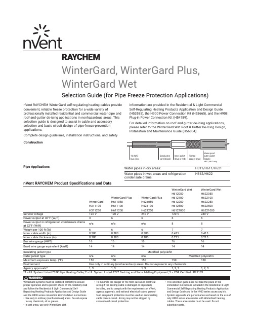
nVent RAYCHEM WinterGard self-regulating heating cables provide convenient, reliable freeze protection for a wide variety ofprofessionally installed residential and commercial water-pipe and roof-and-gutter de-icing applications in nonhazardous areas. This selection guide is designed to assist in cable and accessory selection and basic circuit design of pipe-freeze-prevention applications.Complete design guidelines, installation instructions, and safety information are provided in the Residential & Light Commercial Self-Regulating Heating Products Application and Design Guide (H53585), the H900 Power Connection Kit (H53665), and the H908 Plug-in Power Connection Kit (H54789).For detailed information on roof and gutter de-icing applications, please refer to the WinterGard Wet Roof & Gutter De-Icing Design, Installation and Maintenance Guide (H56804).ConstructionPipe ApplicationsWater pipes in dry areas:H311/H611/H621Water pipes in wet areas and refrigeration condensate drains:H612/H622nVent RAYCHEM Product Specifications and DataWinterGard H311100H311250WinterGard Plus H611050H611100H611250WinterGard Plus H621050H621100H621250WinterGard Wet H612050H612100H612250H612500H6121000WinterGard Wet H622050H622100H622250H622500H6221000Service voltage120 V 120 V 240 V 120 V 240 V Power output at 40°F (W/ft)3666 6 Power output in refrigeration condensate drains at 32°F (W/ft)n/a n/a n/a 88Weight per 100 ft (lb)66677Nom. cable width (in)0.3800.3800.3800.4150.415Nom. cable thickness (in)0.1800.1800.1800.2150.215Bus wire gauge (AWG)1616161616Braid wire gauge equivalent (AWG)1414141414Insulating jacket typeModified polyolefinOuter jacket type n/a n/a n/a Modified polyolefin Maximum exposure temp. (°F)150150150150150Environment Use only in ordinary (nonhazardous) areas. Do not expose to any chemicals.Agency approvals*1, 31, 31, 31, 2, 31, 2, 3*1 = UL System Listed 718K Pipe Heating Cable; 2 = UL System Listed 877Z De-Icing and Snow Melting Equipment; 3 = CSA Certified LR21133WinterGard, WinterGard Plus, WinterGard WetSelection Guide (for Pipe Freeze Protection Applications)2 | Circuit Sizing GuideCatalog ReferencesCatalog Numbers204002468106080100Pipe temperature (F)P o w e r o u t p u t (W /f t )H6XXH3XXWinterGard Power Temperature CurvesCircuit breaker rating (A)Maximum heater length (ft)per circuit at start-up temperature Heating cable type 0°F 32°F 40°F WinterGard 120 V H311 on pipe151502502020025030250250WinterGard Plus 120 V H611 on pipe15125 150 2014019530200200WinterGard Plus 240 V H621 on pipe152002552025034030375400WinterGard Wet 120 V H612 on pipe151251502014019530200200dependent upon heating cable temperature.Watts/ft H62225026240250-ft reel H62250026240500-ft reel H6221000262401000-ft reel* Construction: 1 = braided metal shield only; 2 = waterproof polyolefin outer jacket over braid.** TruckPak consists of 100-foot cable reel, 2 power connections, 1 splice/tee kit, 1 roll application tape, 10 "Electric Traced" labels.Selection TablesUse one of the tables below to help select the correct WinterGard heating cable for your application. (Consult the Residential & Light Commercial Application and Design Guide or H900/H908 Installation Instructions for complete system design information.)Use Table 1 to select heating cables fori nsulated metal pipes. Use Table 2 fori nsulated plastic pipes. Read across the table to find your pipediameter, then drop down to the linecorresponding to the lowest air temperaturefor that application and the correctinsulation thickness. The cell at thatintersection has a particular shade and mayhave a number.The shade indicates which heating cable touse (key to the shades appears to the left ofTable 1). A number in the cell represents thespiraling ratio (feet of heating cable per footof pipe). If no number appears in the cell,straight trace the pipe. If a number doesappear in the cell, spiral trace the pipe. Ifyour spiraling ratio is 2.0, m ultiple-trace thepipe using two straight traces at the 4o’clock and 8 o’clock positions.If your spiraling ratio is 3.0, multiple-tracethe pipe using three straight traces at the 11o’clock or 1 o’clock position and at the 4o’clock and 8 o’clock positions.Example 1Pipe = 2-inch-diameter metal Lowest air temperature = 0°F Insulation thickness = 1 inch Cable length and type = 1 foot of WinterGard H311 per foot of pipe Example 2Pipe = 2.5-inch-diameter plasticLowest air temperature = –20°F Insulation thickness = 1 inchCable length = 1.2 feet of WinterGard Plus H611, H621 or WinterGard Wet H612, H622Table 2. For plastic pipes with fiberglass insulation or equivalent (based on 40°F maintain) | 34 | Typical Assembled System©2019 nVent. All nVent marks and logos are owned or licensed by nVent Services GmbH or its affiliates. All other trademarks are the property of their respective owners. nVent reserves the right to change specifications without notice.RAYCHEM-AR-H55235-WinterGardSelection-EN-1904North AmericaTel +1.800.545.6258Fax +1.800.527.5703**********************。
英特乐热塑驱动传送带拼接系统v20用户手册-Intralox

4 对传送带端头进行预处理 传送带端头的状况 ........................... 4-1 预处理概述 ....................................... 4-1 清洁传送带端头 ............................... 4-2
关停和清洁 ...................................... 8-1 冷却 .................................................. 8-1 装入存储箱 ...................................... 8-1
标准程序
3 安装拼接系统 备齐所需物品 ................................... 3-1 准备输送机 ....................................... 3-1 准备压接工具 ................................... 3-2
嵌入式警告
䘉ᱟањ䙊⭘Ⲵ䆖ؑਧDŽᵜ ѝ䙊⭘Ⲵ䆖ؑਧ⭘Ҿᨀ䟂ᛘ ൘䘋㹼ާփǃ᭵䳌ᧂḕᡆ㔤 ؞〻ᒿᵏ䰤ਟ㜭䙷ࡠⲴড䲙DŽ䈧 Ԅ㓶䰵䈫ؑޣDŽ
传送带拼接系统 v. 2.0
安全
危险严重性面板
“ 危险 ” 表示危险性高的危险事项。如果没 有避免这种危险事项,将会导致死亡或严重 伤害。
“ 警告 ” 表示危险性为中等的危险事项。如 果没有避免这种危险事项,可能会导致死亡 或严重伤害。
英特乐是 Laitram, L.L.C. 的注册商标。
安全
安全
安全信息
避免受伤。 对设备进行操作、故障排查或检 修时,请穿戴个人防护用具 (PPE) (护目镜、耐热手套) 。 尝试对本设备进行操作、故障排 查或检修之前,请先阅读操作 手册。 确保儿童,以及身体、感官、或 心智存在障碍者或者经验或知识 不足者远离拼接系统,尤其在使 用期间更是如此。存有障碍或经 验不足的用户必须接受其安全监 护人的适当监督或培训。 只有在拼接系统安全操作方面接 受过适当培训的人员才能使用该 设备。 拼接系统仅由授权英特乐服务提供商检修更 换。拼接系统中不存在用户可自己维修更换 的组件。 切勿切割、钻孔或以其他方式改装加热板或 温控箱。改装可增加触电和灼伤危险。 请参阅设备上附有以及本文档中包含的安全 标签,以了解详细的安全说明。 如果您对任何安全问题或者您是否可以使用 这些规范执行任务存有疑问,在进行操作之 前请先联系英特乐。 ᵜ䇮઼༷ᓄ᮷ẓѝᡰਜ਼Ⲵ ANSI/ISO ḷㆮ ઼ḷᘇᴹࣙҾᡰᴹઈᆹ⭘֯ޘ䈕䇮༷DŽ ᵜⲴḀӋㄐ㢲वਜ਼䘲⭘Ҿᵜ㢲᧿䘠Ⲵᡰ ᴹ㿴〻Ⲵᆹؑޘࡇ㺘DŽަԆᆹؑޘवਜ਼ ൘ާփⲴ〻ᒿѝˈԕᨀ䟂ᛘᓄⲴ〻ᒿ䴰㾱 ⌘Ⲵᕪࡦ᧚ᯭᡆড䲙ᛵߥDŽ ḕⴻḷㆮ઼ḷᘇؑԕ⺞؍ᘛ䙏ᆼ⨶ޘ䀓ᵜ 䇮༷ѝᡰਜ਼Ⲵ䆖ؑDŽн㾱ᘭ㿶ᵜؑDŽ ᵜؑ⭘ҾѪᛘᨀ؍ᣔDŽ
- 1、下载文档前请自行甄别文档内容的完整性,平台不提供额外的编辑、内容补充、找答案等附加服务。
- 2、"仅部分预览"的文档,不可在线预览部分如存在完整性等问题,可反馈申请退款(可完整预览的文档不适用该条件!)。
- 3、如文档侵犯您的权益,请联系客服反馈,我们会尽快为您处理(人工客服工作时间:9:00-18:30)。
Rev. 1.0
Page 51 of 56
二. 换色程序
1.Open gate。
1.1系统已启动且已加工某种颜色。
1.2用新颜色的料清理机筒。
1.3将热流道各个加热区再升温15-20℃以上(比生产温度)。
1.4注射10-15次。
1.5将注射单元后退,关闭热流道系统的加热元件。
1.6让热流道冷却,此方法可以使流道内的旧料因温度降低而收缩,与流道分离脱落,使新
旧材料可以混合。
1.7启动热流道温度,升温至生产温度。
1.8移回注射单元。
1.9提高注射速度,继续注塑直到制品的颜色可以接受为止。
1.10逐步恢复工艺的设置,使其注射速度和温度恢复为原来的生产工艺。
注意:
有些塑料会分解并释放一些对人体健康有害的气体,请参考塑料供应商的建议,技术资料及安全资料表(Safety Data Sheet),确保生产工作区域的通风良好。
2.Valve gate。
2.1系统已启动且已加工某种颜色。
2.2用新颜色的料清理机筒。
2.3注塑新颜色的原料,直至清除热流道系统中的大部分的旧颜色料。
2.4将注射单元后退,关闭热流道系统的加热元件。
注意:
除非热流道已达塑料的生产加工温度,否则在储料和清理机筒时不要动作阀针。
若未遵守,可能会损坏热流道的阀针和浇口。
2.5让热流道冷却,此方法可以使流道内的旧料因温度降低而收缩,与流道分离脱落,使新旧材料可以混合。
2.6 启动热流道温度,升温至生产温度并开始注塑,直到制品的颜色可以接受为止。
3.拆解清除热流道中残留的杂色料。
检查注塑机射嘴和热流道浇口处是否有旧色残留,并且多次注射清洗无法清理,安热流道的拆装指导拆除热流道并清除热流道头部的杂色料。