2464 #20 X-R控制图及制程能力分析报告
ul2464标准
ul2464标准UL2464标准是指一种多导线、多绕组电缆的标准,该标准适用于内部电气或电子设备的连接线。
UL2464标准要求电缆具有良好的绝缘性能、耐磨性和耐腐蚀性能,以及能够承受一定的机械应力和环境条件。
本文将对UL2464标准进行详细介绍,包括其适用范围、技术要求和产品特性等方面内容。
首先,UL2464标准适用于额定电压不超过300V的多导线、多绕组电缆,用于内部电气或电子设备的连接。
该标准要求电缆的导体采用铜或铜合金制成,绝缘材料应具有良好的绝缘性能,能够在-20°C至80°C的温度范围内正常工作。
此外,电缆还需要具有一定的耐磨性和耐腐蚀性能,以确保在使用过程中不易受到外部环境的影响。
其次,根据UL2464标准,电缆的绝缘材料应符合UL758标准的要求,绝缘电阻应不低于100MΩ·km,绝缘强度应满足规定的测试标准。
电缆的外护套材料应具有一定的耐磨性和耐腐蚀性能,以及抗紫外线和阻燃性能。
此外,根据使用环境的不同,还可以根据UL2464标准的要求选择具有特殊性能的绝缘材料和外护套材料。
最后,根据UL2464标准,电缆的产品特性应符合UL62标准的要求,包括电缆的外径、导体电阻、绝缘厚度、外护套厚度等参数。
在生产过程中,应严格控制电缆的尺寸和性能,确保产品符合UL2464标准的要求。
此外,电缆还需要通过UL认证,以确保产品的质量和安全性能。
总之,UL2464标准是一种多导线、多绕组电缆的标准,适用于内部电气或电子设备的连接线。
该标准要求电缆具有良好的绝缘性能、耐磨性和耐腐蚀性能,以及能够承受一定的机械应力和环境条件。
生产厂家在生产过程中应严格按照UL2464标准的要求进行生产,确保产品符合标准的要求,以满足客户的需求和市场的需求。
UL2464标准的实施将有助于提高电缆产品的质量和安全性能,推动行业的健康发展。
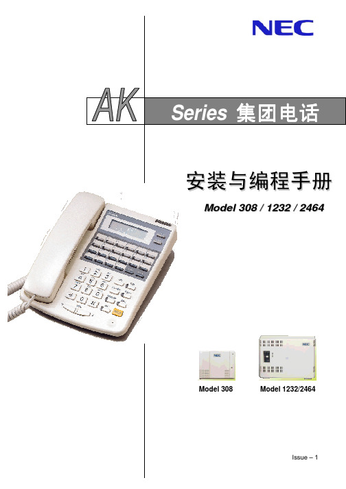
NECAK-2464编程手册
旧型号 1~7
新型号
1
1 1 1
2 1 选用 选用
选用
注2 注2 EXMOH 需要外部音乐声源 注2 注2
FSK 规格
可放置 NP2.6 电池
每电话机一个
注 1: 上表是系统的满配置容量 注 2: AK-308 主机中只能安装两个选配单元板 在 4 个选配单元板中选择两个
< 缩写说明 >
EXMOH: 外部保留音乐 EXP: 外部群呼 KTS: 专用电话机 ME: 主机 SMDR: 分机信息详细记录 SLT: 普通电话机 DUD: 直接通用拨号
32
64
32
64
1
2
10
2
8
16
2
1
2
1
1
2
12
注: 如果连接 DSS 控制台 占用一个内线绳路 如果使用 DSS 控制台 群呼或 BGM 占用内线绳路
1-2
概述
电气规格
专用电话机 普通电话机 门电话
* 电缆线不能安装在室外
分机缆线规格 300 m (0.5 φ 两对双绞线 ) 1,125 m (0.5 φ 一对双绞线) 150 m (0.5 φ 一对双绞线)
6 外线键 标准型专用电话机 6 外线键 显示型专用电话机 12 外线键 标准型专用电话机 12 外线键 显示型专用电话机 6 外线键 标准型专用电话机 6 外线键 显示型专用电话机 12 外线键 标准型专用电话机 12 外线键 显示型专用电话机 壁挂托架 用于新 旧型号电话机
拉出式缩位拨号记录卡
竖式缩位拨号记录卡
(BTD, BTXD TEL)
监听分机 (BTD, BTXD TEL)
SPK 接通扬声器
ul线材标准规格对照表
ul线材标准规格对照表ul线材标准规格对照表主要是为了方便用户在使用ul线材时能够准确地了解不同规格的线材的特点和用途。
ul线材是一种广泛应用于电气设备和电子产品中的线材,具有耐高温、耐磨损、耐腐蚀等特点,因此在不同的场合中都有着重要的作用。
为了满足不同场合的需求,ul线材的规格也是多种多样的,用户在选购时需要根据具体的使用要求来选择合适的规格。
下面将为大家介绍一些常见的ul线材规格及其对照表,希望能够帮助大家更好地了解和选择ul线材。
1. ul1007线材。
ul1007线材是一种通用性较强的线材,常用于内部布线、连接电路板和其他低压电气设备中。
其额定电压为300V,适用于温度在80℃以下的环境。
ul1007线材的导体采用多股铜线,绝缘层采用PVC材料,具有良好的耐磨损和耐油性能。
在选择ul1007线材时,用户需要根据具体的电气设备要求来确定导线截面积和线材长度。
2. ul1015线材。
ul1015线材是一种常用的通用性较强的线材,其额定电压为600V,适用于温度在105℃以下的环境。
ul1015线材的导体采用多股铜线,绝缘层采用PVC材料,具有良好的耐磨损和耐油性能。
ul1015线材常用于内部布线、连接电路板和其他低压电气设备中,用户在选择时需要根据具体的电气设备要求来确定导线截面积和线材长度。
3. ul1061线材。
ul1061线材是一种额定电压为300V的线材,适用于温度在80℃以下的环境。
ul1061线材的导体采用多股铜线,绝缘层采用PVC材料,具有良好的耐磨损和耐油性能。
ul1061线材常用于内部布线、连接电路板和其他低压电气设备中,用户在选择时需要根据具体的电气设备要求来确定导线截面积和线材长度。
4. ul1569线材。
ul1569线材是一种额定电压为300V的线材,适用于温度在105℃以下的环境。
ul1569线材的导体采用多股铜线,绝缘层采用PVC材料,具有良好的耐磨损和耐油性能。
GB-2464 公告版本:3月1996 比例控制阀门电源 EEA-PAM-5 -A-32说明书
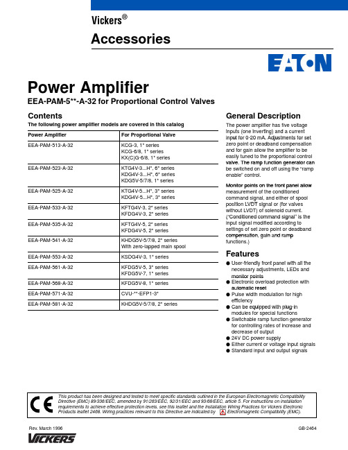
GB-2464Rev. March 1996Power AmplifierEEA-PAM-5**-A-32 for Proportional Control Valves ContentsGeneral Description The following power amplifier models are covered in this catalog pThe power amplifier has five voltage i t (i ti )d tg inputs (one inverting) and a current input for 0-20 mA. Adjustments for set in ut for 020 m . djustments for set zero point or deadband compensation and for gain allow the amplifier to be easily tuned to the proportional control valve The ramp f nction generator canvalve. The ramp function generator can be switched on and off using the “ramp enable” control.Monitor points on the front panel allow Monitor points on the front panel allow measurement of the conditionedcommand signal, and either of spooliti LVDT i l (f l g position LVDT signal or (for valves without LVDT) of solenoid current.(“Conditioned command signal” is the (Conditioned command signal is the input signal modified according to settings of set zero point or deadband compens tion g in nd r mp compensation, gain and ramp functions.)F t FeaturesU f i dl f t l ith ll thF User-friendly front panel with all the necessary adjustments, LEDs and monitor pointsmonitor oints F Electronic overload protection with a tomatic reset automatic resetF Pulse width modulation for high ffi ig efficiency Can be equipped with plug-in F Can be equi ed with lug-in modules for special functionsFSwitchable ramp function generator for controlling rates of increase and decrease of output F 24V DC power supplyF Either current or voltage input signals FStandard input and output signalsVickers ®AccessoriesWarning: Electromagnetic Compatibility (EMC)It is necessary to ensure that the unit is wired up in accordance with the connection arrangements shown in this leaflet. For effective protection, the user’s electrical cabinet, the valve subplate or manifold and the cable screens should be connectedto efficient earth (ground) points. The metal 7-pin connector part no. 934939 should be used for the integral amplifier.In all cases, both valve and cable should be kept as far away as possible from any source of electromagnetic radiation such as cables carrying heavy current, relays and certain kinds of portable radio transmitters, etc. Difficult environments could mean that extra screening may benecessary to avoid the interference.2Front Panel[4]Model523, 525, 533, 535, 561, 568 and 581513Potentiometers[1][2][3][5]LVDT failure, red[6][7][8][10]LED[9]LEDs[11]Potentiometers[13][12]Monitor points Y[14][15][16]Y Ø 2 mm (0.0787I 541, 553[20]Adjust valve zeroPotentiometerElectrical Block DiagramEEA-PAM-523/525-A-32533/5353Operating Data4Model513523525533535541553561568571581Max. solenoid current1,6A1,6A2,7A2,7A3,2A3,2A1,8A2,9A3,2A Amplifier input current at 0V commandsignal (MP1)0,3A0,3A0,3A0,3A1,7A1,7A1,4A1,1A1,7A Deadband compensationFactory setting (% of max. spool stroke)–25%15%10%––10%10%10%Adjustment per direction (% of max. spool stroke from centered position)–0 -50%0 -50%0 -50%––0 -50%0 -50%0 -50%GainFactory setting10%/V10%/V10%/V10%/V10%/V10%/V10%/V10%/V10%/VAdjustment per direction2,5 -10%/V 2,5 -10%/V2,5 -10%/V2,5 -10%/V––2,5 -10%/V2,5 -10%/V2,5 -10%/VZero adjustment (% of max. spool stroke)0 -50%–––+/–25%+/–25%–––5Wiring ConnectionsAmplifier Models to Typical Valve TypeAmplifier Models: 513, 523, 525Amplifier Models: 533, 53567Typical Input Connection Circuitry-A-32Valve Solenoid ConnectionsNote: Connection not polarity sensitive.Protective ground: Connection not required if power supply conforms to VDE 0551/EN 60742/IEC 742Electromagnetic Compatibility (EMC)Notes for Wiring1)Screened cables should be used for the command signals, the solenoid connections and the LVDT connections.2)Particular attention should be paid to the grounding of the screens as shown in the diagrams.3)The screen on the LVDT cable needs to be grounded at both ends. An alternative method to prevent creating earth loops is to use double screened cable with each screen grounded at opposite ends.4)The amplifiers should be mounted in a metal enclosure which is connected to an efficient ground point.Vickers, Incorporated 5445 Corporate Drive P .O. Box 302Troy, Michigan 48007-0302USAVickers Systems Ltd 2/F Chiaphua Centre Yuen Shun Circuit Siu Lek Yuen, Shatin N.T. Hong KongTrinova do Brazil S.A.CEP 07250-270Av. Julia Gaioli, 450Bonsucesso–Guarulhos Sao Paulo 07BrazilVickers Systems Division TRINOVA Ltd P .O. Box 4New Lane, Havant Hampshire PO9 2NB EnglandPlug-in Unit of 3U Height (IEC 297)Installation Dimensions in mm (inches)Printed in U.S.A.E Vickers, Incorporated, 1996 All Rights Reserved。
GC246微处理器多功能数字功率计说明书

GC2464微处理器多功能数字功率计使用维护说明书天津正大电子有限公司GC2464微处理器多功能数字功率计一、概述:本仪器可以同时测量三相交直流电压、电流、功率、频率及功率因数。
该仪器采用8088 16位CPU。
体积小、速度快、对被测功率的功率因数没有限制。
广泛应用于电机、电力、家电、电光源行业以及计量部门的标准表使用,是传统测试手段的换代产品。
仪器的性能及各项技术指标,均达到或超过日本的2533功率计,是进口仪器的替代产品。
本仪器还带有IEEE-488标准接口和RS-232接口,可以和任意型号的微机相连,组成自动测试系统。
二、功能:1、同时测量交直流电压、电流、功率、频率、功率因数、电压失真度、电流失真度。
2、本仪器采用32位数字显示,可以同时显示三相电压、三相电流、一个功率(总功率或Pa.Pb.Pc轮换)、一个频率(或功率因数)。
3、可以输入电压互感器变比。
4、本仪器具有存贮功能,可以对多组测量结果求X ∑X δ n。
5、本仪器带有打字机接口。
6、本仪器带有IEEE-488标准接口和RS-232接口。
7、具有断电存贮功能。
8、本仪器测量量程自动转换。
三、主要技术指标(20/℃±50/℃):1、交流电压:量程:500V 250V。
精度:(±0.1%读数)+(±0.1%量程)。
2、交流电流:量程:5A 2.5A 2A。
精度:(±0.1%读数)+(±0.1%量程)。
3、交流功率:7500W 5000W 2500W 1250W 625W。
精度:(±0.1%读数)+(±0.1%量程)。
4、直流电压:量程:700V 350V。
精度:(±0.1%读数)+(±0.1%量程)。
5、直流电流:量程:7A 3.5A。
精度:(±0.1%读数)+(±0.1%量程)。
6、直流功率:量程:4600W 2450W 1225W。
UL2464 PVC护套线
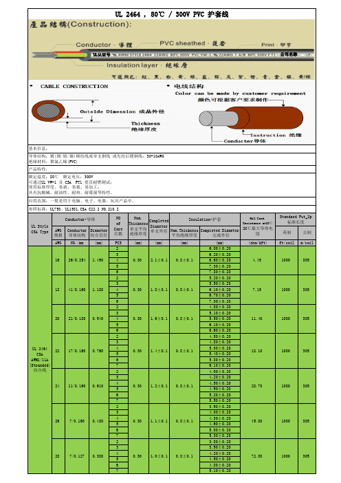
UL 2464 , 80℃ / 300V PVC 护套线基本信息:导体结构:镀(锡/银/镍)铜绞线或单支铜线 或先绞后镀铜线:30-10AWG绝缘材料:聚氯乙烯(PVC)产品特性:额定温度:80℃ 额定电压:300V可通过UL VW-1 及 CSA FT1 垂直耐燃测试;使用标准厚度、易剥、易裁、易加工;具有抗酸碱、耐油性、耐热、耐霉菌等特性。
应用范围:一般是用于电脑、电子、电器、玩具产品中。
参照标准:UL758、UL1581,CSA C22.2 NO.210.2UL Style CSA TypeConductor•导体NOofCore芯数Nom.Thickness单支平均绝缘厚度CompletedDiameter单支外径Insulation•护套MAX.Cond.Resistance at20℃20℃最大导体电阻Standard Put_Up标准长度AWG规格Conductor导体结构Diameter绞合直径Nom.Thickness平均绝缘厚度Compieted Diameter完成外径英制公制AWG NO./mm(mm)PCS(mm)(mm)(mm)(mm)(ohm/kft)ft/coil m/coilUL 2464CSA AWM1/11A (Stranded)绞合线16 26/0.254 1.49020.30 2.1±0.10.8±0.16.00±0.204.45 1000 3053 6.20±0.204 6.60±0.205 7.30±0.206 7.80±0.2018 41/0.160 1.18020.30 1.8±0.10.8±0.15.20±0.207.15 1000 3053 5.50±0.204 6.10±0.205 6.70±0.206 7.30±0.2020 21/0.1800.94020.30 1.6±0.10.8±0.14.80±0.2011.40 1000 3053 5.10±0.204 5.50±0.205 6.10±0.206 6.60±0.2022 17/0.1600.76020.30 1.4±0.10.8±0.14.50±0.2018.10 1000 3053 4.80±0.204 5.00±0.205 5.40±0.206 5.80±0.207 6.10±0.2024 11/0.1600.61020.30 1.2±0.10.8±0.14.00±0.2028.70 1000 3053 4.20±0.204 4.50±0.205 4.90±0.206 5.20±0.207 5.50±0.2026 7/0.1600.48020.30 1.1±0.10.8±0.13.90±0.2045.80 1000 3053 4.00±0.204 4.30±0.205 4.60±0.206 5.00±0.207 5.30±0.2028 7/0.1270.38020.30 1.0±0.10.8±0.13.80±0.2072.80 1000 3053 3.90±0.204 4.20±0.205 4.50±0.206 4.80±0.207 5.10±0.20UL认证号公司名称。
SAE J2464

SAE Technical Standards Board Rules provide that: “This report is published by SAE to advance the state of technical and engineering sciences. The use of this report is entirely voluntary, and its applicability and suitability for any particular use, including any patent infringement arising therefrom, is the sole responsibility of the user.”SAE reviews each technical report at least every five years at which time it may be reaffirmed, revised, or cancelled. SAE invites your written comments and suggestions.QUESTIONS REGARDING THIS DOCUMENT: (724) 772-8512 FAX: (724) 776-0243TO PLACE A DOCUMENT ORDER; (724) 776-4970 FAX: (724) 776-0790SAE WEB ADDRESS Table 1Measurement Accuracies (4)Table 2Shock Levels and Durations (5)Table 3Penetration Characteristics (6)Table 4Thermal Heatup Rates and Durations (9)Table 5Number and Type of Devices to be Shorted (12)Table 6Test Conditions Sequence and Required Actions (13)1.Scope—This SAE Recommended Practice is intended as a guide toward standard practice and is subject tochange to keep pace with experience and technical advances. It describes a body of tests which may be used as needed for abuse testing of electric or hybrid electric vehicle batteries to determine the response of such batteries to conditions or events which are beyond their normal operating range. This document is derived from a similar document originally developed by the U.S. Advanced Battery Consortium. (See 2.2.1.)1.1Purpose—These tests are intended to simulate abuse conditions and potential internally initiated failures thatmay be experienced in electrochemical storage systems. These tests were derived from Failure Mode and Effect Analysis, user input and historical abuse testing. The outcome of testing shall be documented for use by potential users of the tested properties. It is not the intent of this procedure to apply acceptance criteria; each application has its own unique requirements and ancillary support systems. Users of these technologies shall make their own determination as to what measures to take to ensure a sound application of said technology.The tests are designed to provide a common framework for various Electrochemical Storage Systems (ECSS) technologies. The primary purpose of the tests is to gather response information to external/internal inputs.Some tests and/or measurements may not be required for some ECSS technologies and designs if it can be demonstrated that the test is not applicable and the measurement will yield no useful information.Note that the device to be tested using any of the procedures in this document is referred to as an Electrochemical Storage System (ECSS); this terminology may refer to an electrochemical cell, module or complete battery system, depending on the particular test.2.References2.1Applicable Publications—The following publications form a part of this specification to the extent specifiedherein. Unless otherwise specified, the latest issue of SAE publications shall apply.2.1.1SAE P UBLICATIONS—Available from SAE, 400 Commonwealth Drive, Warrendale, PA 15096-0001.SAE J1715—Electric Vehicle Terminology2.2Related Publications—The following publications are provided for information purposes only and are not arequired part of this document.2.2.1USABC P UBLICATION—Available from NTIS, 5285 Port Royal Road, Springfield, VA 22161.Electrochemical Storage System Abuse Test Procedure Manual, February 1999 Version 1.0,T. Unkelhaeuser & D. Smallwood, published as Sandia Laboratories report SAND99-04972.2.2AIHA P UBLICATION—Available from American Industrial Hygiene Association, 1997, AIHA Publications,Department #796, Alexandria, VA 22334-0796.Emergency Response Planning Guidelines, Level 23.Definitions3.1Electrochemical Storage Systems (ECSS)—A device for storing electrical energy in a reversibleelectrochemical form for use in mobile or stationary applications. In this document, the ‘device under test’is always referred to as an ECSS whether it consists of a single cell, a multiple cell assembly or module, or a complete battery pack or system.3.2Emergency Response Planning Guidelines, Level 2 (ERPG-2)—ERPG-2 levels are defined as themaximum airborne concentration below which it is believed that nearly all individuals could be exposed for up to 1 h without experiencing or developing irreversible or other serious health effects or symptoms which could impair an individual’s ability to take protective action. This guideline is taken from the American Industrial Hygiene Association. Other world standards with like intent may be substituted, because use of these concentration levels is for comparison purposes only.3.3Fully Charged—100% State of Charge. The state of an ECSS after a full charge cycle as specified by theECSS manufacturer. For purposes of this document, an ECSS is considered fully charged up to 4 h after the completion of the charge cycle provided that the state of charge is not expected to fall below 95%.4.Technical Requirements4.1General Test Guidelines—Subjecting batteries to conditions outside their intended operating rangenecessarily involves some risk of unintended failures. The responsible testing organization should consult the battery manufacturer for information regarding the possible consequences of such failures, including the potential release of hazardous substances, so that appropriate precautions can be taken for the safety of testing personnel.4.1.1H AZARDOUS S UBSTANCE M ONITORING—The release of hazardous substances should be measured andreferenced to the ERPG-2 levels. ERPG-2 refers to the Emergency Response Planning Guidelines, Level 2, from the American Industrial Hygiene Association. ERPG-2 levels are defined as the maximum airborne concentration below which it is believed that nearly all individuals could be exposed for up to 1 h without experiencing or developing irreversible or other serious health effects or symptoms which could impair an individual’s ability to take protective action. Use of these levels as a reference is done for comparison purposes only.Tests which require hazardous substance monitoring should be conducted in a closed volume of appropriate size to accommodate the test article and provide adequate air space to ensure a “normal”atmosphere. Any released gas concentration in that volume shall be normalized to a 1 m3 volume for quantitative analysis. If it is not practical to perform any test in a closed volume due to test article size, it is permissible to perform the test out of doors provided that wind speed is 3 mph or less. A minimum of three hazardous substances monitors, approximately equally spaced around the unit, should be placed as close as reasonable to the test and moved as close as practical to the ECSS after the test. (The rollover test is an exception to this.) Hazardous substance monitors shall be selected with respect to anticipated release products;manufacturer’s input will generally be required to determine this. If it is reasonable to expect that a specific technology will not vent during a particular test, or that gas collected will not be significantly different from that previously collected, gas collection and analysis are not required. The time resolution of such sampling is not specified because of the wide variability in test dynamics and release amounts/rates expected.The flammability of any expelled materials must be determined. The lower limit of flammability in air is used for flammable gases and liquids. For example, the lower limit of flammability in air for H2 is 4%.For substances not considered hazardous, the EPA reportable release limits are used as a reference for comparison purposes only. A release means any spilling, leaking, pumping, pouring, emitting, emptying, discharging, injecting, escaping, leaching, dumping, or disposing into the environment.4.1.2T EST C ONDITIONS AND M EASUREMENT A CCURACIES—All ECSS test articles shall be in a fully charged state, atnormal operating temperature with any cooling media in place and thermal control systems running unless specifically stated otherwise. All test articles will be observed for a time period of at least 1 h or until such time that said test article is judged safe to handle after each test unless specifically stated otherwise.Except where specifically stated otherwise (e.g., temperature abuse tests), the ambient temperature for any tests defined in this document shall be 25 °C ± 3 °C, and the ECSS environment shall be stabilized at this temperature prior to the start of testing.Measured data shall be acquired at rates and with accuracies adequate to assure that the usefulness of the test data is not compromised. In the absence of more specific requirements by the test sponsor, the measurement accuracies in Table 1 shall be considered acceptable. Because of the wide variety of test dynamics, it is not possible to specify absolute data rates. However, the required data for a particular test shall be acquired at a rate such that errors due to test dynamics will not exceed the required measurement accuracies. For example, if the required accuracy for a given test is 10 °C, the temperature shall be measured sufficiently often that measurement delays will not contribute more than 10 °C error to the resulting data during the important parts of the test.TABLE 1—MEASUREMENT ACCURACIESParameter AccuracyTemperature±2 °C ± 5% of readingVoltage, Current, Resistance1% of readingVibration, Deformation4% of readingHazardous Substance Concentration10% of reading4.1.3N UMBER, C ONDITION, AND S IZE OF B ATTERIES TO BE T ESTED—Initial testing will probably be with a new ECSS,as systems or subsystems which have seen part of their useful life will not be available. Future efforts may include an ECSS well into, or near the end, of its useful life. Permutations of state of charge, system age, and temperature should be implemented at the test sponsor’s or manufacturer’s discretion based on the most susceptible condition of the technology. Note that information will generally be needed from the ECSS manufacturer to determine what types of hazardous substances (if any) may be expected to be released during a given test.Abuse testing is to be performed to characterize the ECSS response to undesirable conditions or environments associated with carelessness, poorly informed or trained users or mechanics, failure of specific ECSS control and support hardware, or transportation/handling incident or other accidents involving the ECSS. Some of these conditions can reasonably be expected to be encountered infrequently, but nevertheless represent conditions for which the ECSS was not designed or intended for use. Some of the tests are not applicable to all candidate ECSS technologies. Many of these tests may result in intentional destruction of the device under test. The required number of batteries to be subjected to testing will depend on actual performance (e.g., a single ECSS of some types may be capable of surviving all but the crush test, whereas for other technologies, as many as 3 to 4 batteries may be required). It is acceptable to use a new ECSS for each test. However, in many cases, it may be economically or technically desirable to subject a single device to multiple tests, either to reduce the number of test articles required or to study the interaction of multiple events (e.g., mechanical shocks followed by penetration, immersion, or high temperatures.)In general these tests should be conducted at the lowest level of assembly for which meaningful data can be gathered, i.e., cell, multi-cell module, or complete battery pack or system. The recommended lowest level of assembly to be used for each test is indicated on the title line for each test. Tests are grouped into three categories: mechanical, thermal, and electrical abuse. Some tests have been arbitrarily classified as they contain more than one of these elements.4.2Mechanical Abuse Tests—The mounting and support of the ECSS shall be as similar as possible to themanufacturers recommended EV installation requirements for mechanical shock and vibration tests. If the support structure has any resonance below 50 Hz, the input will be determined by the average of the acceleration at each of the major support points.4.2.1S HOCK T ESTS (M ODULE L EVEL OR A BOVE )4.2.1.1Test Description—Subject the ECSS to shock events at one or more defined shock levels. The low level shock is a robustness test which an ECSS will generally survive without damage. The mid-level shocks are more severe and the ECSS may be inoperable after the test. Shock levels and durations are defined in Table 2. Each shock level is specified in terms of a velocity change and a corresponding maximum duration. (Shock duration is defined as the time between 10% and 90% of peak value.) Achieving this velocity change over this maximum duration is the goal of the test; however, the characteristics of the acceleration (deceleration) pulse are limited by the test equipment used.The maximum duration places lower limits on the peak acceleration which must be seen during the test.For example, for the low level test, the lowest possible acceleration meeting the requirements would be achieved if the acceleration was an ideal square wave of about 12.5 g. The minimum peak acceleration in Table 2 is specified at about twice this level, recognizing that an ideal square wave cannot be achieved in a real test. It is expected that a simple pulse shape (such as a half-sine) will be used for the test, but the pulse shape is not specified to allow as much flexibility as possible in the testing laboratory. Advanced techniques which more accurately simulate actual deceleration time histories are not excluded. It is generally in the interest of the ECSS manufacturer to keep the pulse duration as long as possible while meeting the specification. However, if the ECSS is robust, it may be desirable to increase the peak acceleration and/or reduce the duration if this reduces test complexity and cost.4.2.1.2Measured Data—The following data shall be collected as part of this test:a.Air concentrations of hazardous gases, or concentrations of hazardous liquids or solids, expected to be released shall be collected and analyzed as a function of time. b.Acceleration input to ECSS case, with a minimum of 2 kHz bandwidth.c.Measurements of the ECSS deformation after the test.d.Temperature of the ECSS case as a function of time.e.Potential and resistance of the ECSS case with respect to the positive and negative terminals before and after the test.f.Still photographs, of the test setup, and the ECSS before and after the test.g.High-speed motion pictures of test, 400 frames/s.4.2.2D ROP T EST (P ACK L EVEL O NLY )4.2.2.1Test Description—Drop the ECSS (free drop) from 10 m (33 ft) onto a centrally located, cylindrical object(telephone pole or equivalent) having a radius of 150mm. The ECSS shall impact across the radius (not the end) of the cylindrical object. A horizontal impact with an equivalent velocity change is acceptable.The ECSS should be observed for a minimum of 1 h after the test. Note that this test may not be suitable for use with batteries whose enclosures are not independent structural components.TABLE 2—SHOCK LEVELS AND DURATIONSLevelVelocity (m/s)Max Duration (ms)Minimum Acceleration Acceptable Pulse Form Low6.7 5520 g for 11 ms 25 g 30 ms halfsine Mid-111.1 6530 g for 16 ms 35 g 51 ms halfsine Mid-213.3 11020 g for 22 ms 25 g for 60 ms halfsine4.2.2.2Measured Data—The following data shall be collected as part of this test:a.Air concentrations of hazardous gases, or concentrations of hazardous liquids or solids, expected tobe released shall be collected and analyzed as a function of time.b.Acceleration input to ECSS case, with a minimum of 10 kHz bandwidth.c.Measurements of the ECSS deformation after the test.d.Temperature of the ECSS case as a function of time.e.Potential and resistance of the ECSS case with respect to the positive and negative terminals beforeand after the test.f.Still photographs, of the test setup, and the ECSS before and after the test.g.High-speed motion pictures of test, 400 frames/s.4.2.3P ENETRATION T EST (C ELL L EVEL OR A BOVE)4.2.3.1Test Description—Penetrate the ECSS with a mild steel (conductive) pointed rod. The rate of penetrationshall be 25 cm/s or less. The diameter of the rod and the depth of penetration can be found in Table 3.The orientation of the penetration shall be perpendicular to the electrode plates.TABLE 3—PENETRATION CHARACTERISTICSSize of Test Object Diameter of Rod Minimum Depth of PenetrationCell 3 mm Through cellModule/Pack20 mm Through 3 cells or 100 mm4.2.3.2Measured Data—The following data shall be collected as part of this test:a.Air concentrations of hazardous gases, or concentrations of hazardous liquids or solids, expected tobe released shall be collected and analyzed as a function of time.b.Measurements of the ECSS deformation after the test.c.Temperature of the ECSS case as a function of time.d.Potential and resistance of the ECSS case with respect to the positive and negative terminals beforeand after the test.e.Still photographs, of the test setup, and the ECSS before and after the test.f.High-speed motion pictures of test, 400 frames/s.g.The ECSS should be observed for a minimum of 1 h after the test with the rod remaining in place.4.2.4R OLL-OVER T EST (M ODULE L EVEL OR A BOVE)4.2.4.1Test Description—Rotate the ECSS one complete revolution in 1 min in a continuous slow roll fashion, andobserve whether any material leaks from the ECSS. Then rotate the ECSS in 90 increments for one full revolution. Observe the ECSS for 1 h at each position and for a minimum of 1 h after the test.4.2.4.2Measured Data—The following data shall be collected as part of this test:a.Air concentrations of hazardous gases, or concentrations of hazardous liquids or solids, expected tobe released shall be collected and analyzed as a function of time.b.Temperature of the ECSS case as a function of time.c.Potential and resistance of the ECSS case with respect to the positive and negative terminals beforeand after the test.d.Still photographs of the test setup and the ECSS before the test and at each rotational position.e.Analysis of any substance that may leak from the battery, particularly its flammability.4.2.5I MMERSION T EST (M ODULE L EVEL OR A BOVE)4.2.5.1Test Description—With the ECSS in its normal operating orientation, immerse the ECSS in salt water(nominal composition of seawater) for a minimum of 2 h or until any visible reactions have stopped. The water depth must be enough to completely submerge the ECSS.4.2.5.2Measured Data—The following data shall be collected as part of this test:a.Temperature of the ECSS case as a function of time.b.Air concentrations of extremely hazardous substances as a function of time, measured above theECSS with one or more hazardous substance monitors.c.Potential and resistance of the ECSS case with respect to the positive and negative terminals beforeand after the test.d.Still photographs, of the test setup, and the ECSS before and after the test. The entire test shall bevideo taped.e.If there are clearly visible releases of substances from the ECSS in the water, samples of these shouldbe analyzed for toxicity.4.2.6C RUSH T EST (C ELL L EVEL OR A BOVE)4.2.6.1Test Description—The ECSS shall be crushed between a fixed surface and a textured platen. The platenshall have semi-cylindrical intruders that have a 75 mm radius and placed 30 mm from one another across the face of the platen. Figure 1 illustrates the approximate shape of the platen.FIGURE 1—CRUSH TEST PLATENThe ECSS shall be at nominal operating temperature. It shall have all integrated control and interconnect circuitry (if provided--may not be applicable at the cell level) in place and operating. An ECSS is to be crushed once in each of the three axes (using a different ECSS for each crush), with the irregular surface of the platen at the most vulnerable location. For each unit, crush to 85% of the initial dimension and hold for 5 min. After the hold period, continue the crush to 50% of the initial dimension. The crush force may be limited to a maximum of 1000 times the weight of the ECSS. If the test is performed outside, the wind speed should be <3 mph. A minimum of three hazardous substances monitors, approximately equally spaced around the unit, should be placed as close as reasonable to the test and moved as close as practical to the ECSS after the test.4.2.6.2Measured Data—The following data shall be collected as part of this test:a.Air concentrations of hazardous gases, or concentrations of hazardous liquids or solids, expected tobe released shall be collected and analyzed as a function of time.b.Internal and external ECSS temperature.c.ECSS voltage, as appropriate.d.Video and still photographs of the ECSS before, during, and after the test.4.3Thermal Abuse Tests4.3.1R ADIANT H EAT T EST(C ELL L EVEL OR A BOVE)4.3.1.1Test Description—With the ECSS at 80% SOC, expose it to high temperature for 10 min by placing itinside a radiant heating fixture. The fixture shall be programmed to reproduce the temperature experienced in a fuel fire (890 °C nominal). The programmed temperature shall be achieved within 90 s and held for a period of 10 min or until another condition occurs which would prevent the completion of the tests. The ECSS should be in its normal operation orientation and will not be insulated or protected unless this is the standard configuration for the test article. If the ECSS ignites, it may be extinguished with a method appropriate for the technology.The test fixture for this test is a cylindrical metallic fixture whose inside is coated such that it will radiate approximately like a black body. The exterior is radiated with radiant heat. The test temperature is controlled by thermocouples mounted on the interior surface of the fixture, with the device under test placed in the center of the fixture such that it does not contact the fixture walls. A sketch of such a test fixture is shown in Figure 2. If such a fixture is not available, this test can be conducted using some other means (e.g., a tube furnace and conveyer mechanism) that would expose the ECSS to non-contact heat from a cylindrical radiating surface at 890 °C, where the surface temperature which the ECSS sees increases from ambient to the test value within 90 s.FIGURE 2—TEST FIXTURE4.3.1.2Measured Data—The following data shall be collected as part of this test:a.Air concentrations of hazardous gases, or concentrations of hazardous liquids or solids, expected tobe released shall be collected and analyzed as a function of time.b.Temperature of the ECSS case as a function of time.c.Potential and resistance of the ECSS case with respect to the positive and negative terminals beforeand after the test.d.Video and still photographs, of the test setup, and the ECSS before, during and after the test.4.3.2T HERMAL S TABILITY T EST (C ELL L EVEL OR A BOVE)4.3.2.1Test Description—The ECSS shall be in a fully charged state and at normal operating temperature at thebeginning of the test. If the temperature at which a major exothermic reaction occurs is known, the test may begin at 10% less than this temperature to save time. Place the ECSS in a device or chamber capable of heating the ECSS to 200 °C above its operating temperature. For cells, it is desirable for this device to be capable of maintaining a near adiabatic state (Accelerated Rate Calorimeter (ARC) apparatus or similar). Increase the temperature in increments as shown in Table 4, and hold at each temperature step for the minimum time shown in Table 4, or until any self heating is detected. If self heating is detected, it is desirable for the chamber temperature to track the ECSS temperature until it stabilizes; this will minimize the test duration. The temperature is then increased to the next increment and continued as described previously until either (a) additional self heating is detected, (b) the temperature reaches 200 °C above the operating temperature of the ECSS or (c) a catastrophic event occurs (e.g., venting or major damage to the ECSS.)If the ECSS experiences a thermal runaway, the test should be repeated to further define the exact thermal stability limit. Increase the temperature at a constant rate to the first step below the event temperature. The temperature will then be increased in 2 °C increments and held for a minimum of 1 h until the event is repeated and the thermal stability limit is defined.This test should be repeated with cells that have been overcharged to 150% of the rated capacity (using the conditions of Procedure 4.4.3) and cells that have been cycled to 50% and 100% of nominal life. The overcharge may be limited to a value that will not physically damage the cell (e.g., by venting or rupture) prior to conduct of the thermal stability test.4.3.2.2Measured Data—The following data shall be collected as part of this test:a.Temperature(s) at which venting occursb.Temperature(s) of any smoke generation or other major eventsc.Cell temperature profile with respect to timed.Oven/chamber temperature profile with respect to timeTABLE 4—THERMAL HEATUP RATES AND DURATIONSECSS Assembly Level Heatup Rate Increment(°C)Hold Time at EachTemperature Step(min)Cell530 Module or higher (exothermtemperature known)10120Module or higher (exothermtemperature unknown)201204.3.3C OMPROMISE OF T HERMAL I NSULATION(M ODULE LEVEL OR ABOVE)4.3.3.1Test Description—With the ECSS at nominal operating temperature and fully charged, compromise theinsulation system integrity or other applicable device and allow the case external temperature to reach steady state.4.3.3.2Measured Data—The following data shall be collected as part of this test:a.Internal and external temperature distribution4.3.4O VERHEAT/T HERMAL R UNAWAY T EST (M ODULE L EVEL OR A BOVE)4.3.4.1Test Description—With the ECSS at nominal operating temperature, fully charged, contained in a closedvolume, and all thermal controls (primary and secondary) disabled, perform C/1 cycling utilizing the manufacturers defined charge algorithm for 20 cycles with no rest period between charge or discharge.Perform three baseline C/3 cycles after the test with thermal control active to determine the effects on the ECSS.4.3.4.2Measured Data—The following data shall be collected as part of this test:a.Note any venting of the ECSSb.Internal (if possible) and external ECSS temperaturec.Voltage and resistance of the ECSS case with respect to the positive and negative terminals beforeand after the testd.Still photographs of the ECSS before, during, and after the teste.ECSS voltage and current as a function of time4.3.5T HERMAL S HOCK C YCLING (C ELL L EVEL OR A BOVE)4.3.5.1Test Description—With the ECSS at 50% State of Charge, contained in a closed volume, and all thermalcontrols (primary and secondary) disabled, thermally cycle the ECSS with ambient air cycling between 80°C to –40 °C. The time to reach each temperature extreme shall be 15 min or less; this test may be performed either through the use of a fast-response chamber, or by moving test articles between two chambers at the two test temperatures. The ECSS shall remain at each extreme for a minimum of 1 h at the cell level, 6 h at the module level, or as required to reach uniform temperature at the pack level. A total of five cycles shall be performed. After thermal cycling, inspect the ECSS for any damage, paying special attention to any seals that may exist. Also, determine whether control circuitry, if any, is operational.Perform three C/3 discharge cycles at 25 °C ambient air temperature (using the manufacturers recharge algorithm) to determine immediate effects of the thermal cycling.4.3.5.2Measured Data—The following data shall be collected as part of this test:a.ECSS voltage during thermal cyclingb.Note any venting of the ECSSc.Voltage and resistance of the ECSS case with respect to the positive and negative terminals beforeand after the testd.Still photographs of the ECSS before and after the test。
AWM2464线检验标准
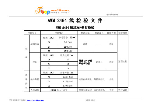
德信诚培训网AWM 2464 线检验文件AWM 2464线过程/例行检验检验项目检验要求检测方法检测器具抽样方案检验规则绞丝结构检查线规(AWG)参考结构....(根/mm)计数——首检过程检验26 7/0.16024 11/0.16022 17/0.160绞距线规(AWG)最大绞距(mm)测量10个绞距的平均值钢直尺首检26 1524 1822 20绝缘挤包绝缘外径线规(AWG)参考外径(mm)连续自动测量外径测控仪全检26 1.05±0.0524 1.15±0.0522 1.30±0.05火花试验3KVAC电压不击穿绝缘火花试验火花试验机全检例行试验德信诚培训网AWM 2464线过程/例行检验检验项目检验要求检测方法检测器具抽样方案检验规则护套外径芯数和线规(AWG)外径(mm)连续自动测量外径测控仪全检过程检验2/C 22 4.20±0.153/C 22 4.50±0.154/C 24 4.40±0.153/C 24 4.00±0.158/C 24 5.40±0.159/C 24 5.80±0.2011/C 24 5.25-5.518/C 24?2/C 26 3.60±0.154/C 26 4.00±0.156/C 26 4.60±0.207/C 26 4.70±0.158/C 26 4.90±0.1512/C 26 5.90±0.25。
- 1、下载文档前请自行甄别文档内容的完整性,平台不提供额外的编辑、内容补充、找答案等附加服务。
- 2、"仅部分预览"的文档,不可在线预览部分如存在完整性等问题,可反馈申请退款(可完整预览的文档不适用该条件!)。
- 3、如文档侵犯您的权益,请联系客服反馈,我们会尽快为您处理(人工客服工作时间:9:00-18:30)。
3
审核:
50% 0.67 0.67
D
以上 以下 以下
编 制
表单编号:ZW-28-001 A0
N= 138
平 均
X
1.30 1.30 1.30 1.29 1.30 1.29 1.30 1.30 1.30 1.29 1.29 1.29 1.30 1.28 1.29 1.29 1.29 1.28 1.30 1.28 1.29 1.28 1.30 0.00 0.00
R
0.02 0.02 0.02 0.02 0.02 0.02 0.02 0.02 0.02 0.02 0.02 0.02 0.02 0.00 0.02 0.01 0.02 0.00 0.01 0.01 0.02 0.00 0.01 0.00 0.00
1.3 10.3 10.3 10.3 10.2 19.2 9
1.2 18.2 19.2 18.2 18.2 18.2 8
1.2 18.3 10.2 18.2 19.3 10.3 0
1.2 18.2 18.2 18.2 18.2 18.2 8
1.3 10.3 10.3 10.3 10.2 19.2 9
1.30 1.30 1.28 1.30 1.30 1.30
1.29 1.29 1.29 1.28 1.28 1.30
1.3 10.2 18.3 10.3 10.3 10.3 0
1.3 10.3 10.2 18.3 10.3 10.2 8
1.3 10.3 10.3 10.2 18.3 10.3 0
1.3 10.2 18.3 10.3 10.3 10.2 9
日期/ 時間
618
6-18 6-18 6-18 10:3 13:3 15:30
619
619
619
619
620
620
620
620
620
620
620
620
R圖
0.03
0.01
0.00
6- 620 20
生产 部门
机台 操号作 6-者6-
20 20
生产
物料编号
抽樣方法 日期
抽检 2019/6/20
合 計
0.05
0.03
R 0.01 管 制 -0.01 图 -0.03
-0.05 1 2 3 4 5 6 7 8 9 10 11 12 13 14 15 16 17 18 19 20 21 22 23 24 25
PP = 1.79 Ca = 18.84% CPK= 2.38 CP = 2.93 Grade = A+
等級 Ca Cp Cpk 1.67 1.67
A+
MIN MIN
过程能力分析:
NO
1
问题点
2
原因分析
过程能力特足!!
等
改善方案
级
划
分
标
准
12.5% 1.33 1.33
A
MAX 1.67 1.67
12.5% 1.00 1.00
B
25% 1.33 1.33
25% 0.67 0.67
C
50% 1.00 1.00
7.78 7.77 7.78 7.73 7.78 7.76 7.78 7.778 7.72 7.71 7.75 7.68 7.78 7.69 7.75 7.68 7.78 0.00 0.00
ΣR= 0.36
量測數值的判定條件
> USL 藍色 < LSL 紅色
深圳市展旺连接器有限公司
X-R控制图
控制图编号:
产品名称
2464 #20 端子 (1123343-1型
号)
規 格 標 準 群組數大小 管 制 X 圖
上限 USL 1.35
6
上限 UCL 1.30
管制項目
压端高度
中心限CL 1.30
總組數 中心限CL 1.29
測量單位
mm
下限 LSL 1.25
23
下限 LCL 1.28
1.2 18.2 18.2 18.2 18.2 18.2 8
1.2 18.2 18.3 10.3 10.2 18.2 8
1.2 19.2 18.2 18.2 19.2 18.2 9
1.2 18.3 10.2 18.2 19.3 10.3 0
1.2 18.2 18.2 18.2 18.2 18.2 8
批號1 2 3
4 5 6 7 8 9 10 11 12 13 14 15 16 17 18 19 20 21 22 23 24 25
ΣX= 178.21
樣1 本2 測3 定4 值5
6
ΣX
1.3 10.3 10.2 18.3 10.3 10.3 0
1.30 1.28 1.30 1.29 1.30 1.30
1.3 10.3 10.2 18.3 10.3 10.3 0
1.2 18.3 10.3 10.3 10.3 10.2 8
1.3 10.2 18.3 10.3 10.2 18.3 0
1.2 19.2 19.2 18.3 10.3 10.3 0
1.3 10.3 10.3 10.3 10.3 10.2 8
X= 1.29 R= 0.01
1.60
1.40 X
1.20
x 1.00
管 0.80 制 0.60 图 0.40
0.20
0.00
預估不良率 (PPM)
0
製程能力分析
StSdi.gDmeva.
= PPK=
0.01 0.01 1.46
x
管 制 图
0.00 1 2 3 4 5 6 7 8 9 10 11 12 13 14 15 16 17 18 19 20 21 22 23 24 25