金丝球焊机7700E中文说明书
IWC5CCL_那电焊机中文说明书_

电阻焊接控制装置IWC5-10136-F1-CCL 使用说明书PH :交流IWC:逆变-----重要-----在使用这个装置之前,先看一下说明书。
如果不看说明书就使用的话,有可能发生事故。
在这本说明书里,有关于注意事项根据危险度以下列标记分类说明。
危险在预测使用者有死亡或者受重伤的危险情况下表示。
警告在估计使用者有死亡或者受重伤的可能性时表示。
在估计使用者受重伤的情况以及东西损害的发生的情况下表示。
注意触电注意表示有触电的可能性。
首先为了能安全的使用,在使用的时候,且在装置的周围按照以下的安全确认进行操作。
一旦忽视了安全确认,将关系到发生装置的破损,伤害,人命的事故。
但是,下列项目是其中一例,并非全部。
经常注意安全。
危险1.这个装置是使用高电压的。
确认在打开门扇之前关闭电源,在关闭门扇后放电。
如果在有电源的状态下打开门扇的话,将导致触电等事故的发生。
2.逆变器式电阻焊接控制装置本装置使用电容器,即使断开电源也存储有高电压。
要在确认放电后进行点检。
疏忽了确认的话会导致事故的发生不仅是「Charge」灯,也要通过测电棒等来确认安全。
放电的确认:1.有「放电SW」时连续按住「放电SW」,确认「Charge」灯灭。
2.没有「放电SW」时断开电源的话就开始放电,所以要确认「Charge」灯灭。
警告1.在接通电源前要确认正规的电源电压设备是否连接着。
如果连接以及电压有异常的话将关系到装置的破损。
2.在接通电源期间即使装置没有在操作也不要接近可动部分。
如果不注意的话将导致事故.3.在切断电源前先确认根据气压水压等可动部周围是否有人。
如果忽视了确认将导致事故的发生。
4.在电源切断期间操作时要设置警告标识。
如果没准备时通入电源的话将导致事故。
5.遮断器断开时的注意(只限逆变器式电阻焊接控制装置)发生遮断器断开的情况时,请检查(a)焊接变压器的内部有无漏气(b)是否由于焊接变压器一次电缆的摩擦导致了短路事故(c)焊接变压器的二次二极管有无破损(d)一次电缆有无短路。
科信半导体焊接设备系列GW-803A型超声波金丝球焊机使用说明书
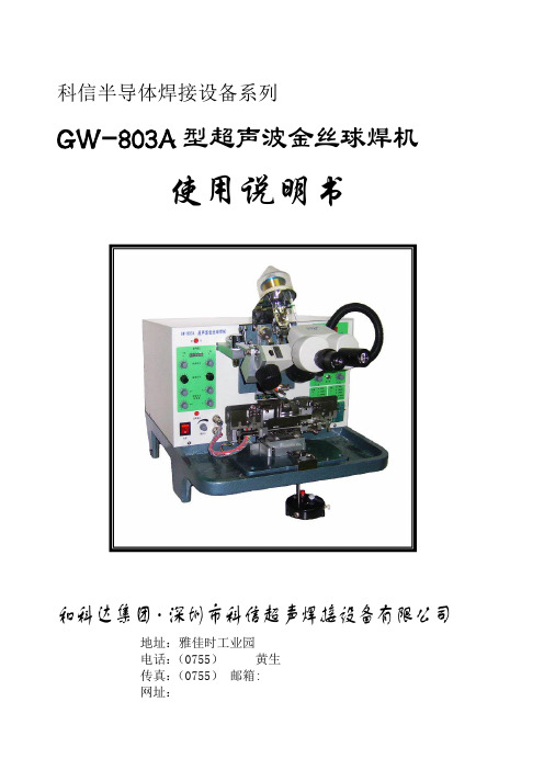
科信半导体焊接设备系列GW-803A型超声波金丝球焊机使用说明书和科达集团·深圳市科信超声焊接设备有限公司地址:雅佳时工业园电话:(0755)黄生传真:(0755)邮箱:网址:目录第一章、机器概述 (2)1.用途介绍 (2)2.功能介绍 (2)3.技术指标 (3)第二章、机器部件介绍与安装指南 (5)1.焊机部件 (5)2.安装指南 (5)第三章、机器操作及调整说明 (8)1.机器操作及调整 (8)2.机器的调整 (14)3.焊接动作程序循环 (17)4.机器操作模式 (18)第四章、机器的日常保养说明 (20)1.清洁部位 (20)2.初始压力参数检查 (20)第五章、机器常见故障及排除 (21)第一章、概述一、用途介绍GW-803A超声波金丝球焊机是针对发光二极管、中小型功率三极管、集成电路及特殊设计半导体等电子器件进行内部引线焊接所设计的专业设备。
焊接过程全部采用微电脑程序化控制,焊头部分的上下运动、位移及焊接工作台的运动均采用步进电机驱动、精密导轨和螺杆传动,确保焊机动作灵活、定位准确、速度快,使之适用于半导体器件内部引线的焊接。
焊接时间、瞄准时间、焊接功率及照明灯亮度等调节旋钮位于左面板,焊接温度、打火强度、焊接压力、弧形设定及焊接模式等调节旋钮位于右面板,可针对不同焊接材料调整相应参数,各指示简洁明了,调整方便,简单调节即可达到最佳焊接状态,极大地提升了工作效率。
各参数调整采用精密电位器,输出稳定可靠,保证金丝烧球和焊接质量稳定可靠、一致性好。
焊机还设有烧球不成功、支架过片到位等声音报警装置,使操作控制更简单明了。
二、功能介绍GW-803A超声波金丝球是我公司最新研制的系列产品之一,相对于市场上其他类似型号的焊机,增加了许多新功能:(1)连续全自动焊接功能:设定好相应的焊接参数后,操作一次可自动连续完成一个支架20只灯杯的左右线焊接,可极大提高焊接效率;其中焊接时的芯片电极的正负极瞄准时间可分别调整;通过选择“单左”或“单右”,还可以进行左线或右线的单向单线的连续全自动焊接;支架打线到最后一颗后,可自动停止焊接动作;(2)连续半自动焊接功能:设定好相应的焊接参数后,操作一次可自动连续完成一个只灯杯的左右线焊接,可大大提高焊接效率;其中焊接时的芯片电极瞄准时间可调整;(3)多种弧形选择:左焊和右焊的弧形各有5种选择,有低弧形、普通弧形、深杯弧形、食人鱼弧形、大功率弧形等;可根据产品选择相应的弧形,简单明确,每种弧形均可调出任意多种设定;弧形的选择可由操纵盒上的线夹开关循环设定;(4)半自动二焊自动瞄点功能:半自动焊接时,可选择一焊完成后劈刀自动跳到二焊瞄准点位置,手动瞄准位置后直接焊接;可针对固晶位置偏差大、较大IC芯片、支架二焊点较差(焊接位置不确定)等情况减少焊接时间,提高效率;机器其他通用功能:(1)劈刀超声测试功能:检测劈刀安装是否正确,大大降低了非机器原因的虚焊机率;(2)超声波焊接功率四道输出:每个焊点(包括左右线的一焊点、二焊点和补球)超声波功率输出可以调节,保证了焊点外观和拉力的一致性,确保了焊接品质;(3)二焊点补球功能:当二焊焊接材料较差时,可直接在二焊点上自动补上一个金球,杜绝了二焊点虚焊缺陷;其中补球功率和补球跨度均可调整记忆;(4)左右线一焊点功率调整:不使用补球功能时,左右线一焊点功率可分别调整,其中“芯片”功率为右线一焊点功率,“补球”功率为左线一焊点功率;使用补球功能时,左右线一焊点功率统一由“芯片”功率设定;(5)自动跳线:左右双向焊接时,左线焊接完成后劈刀可直接跳到右线的一焊点上方,减少瞄准时间,保护左线不被碰倒,提高焊接效率;(6)自动参数记忆:左右双向焊接时,左右线的一二焊点瞄准高度和拱丝高度均可调整记忆,可适合各种高度的晶片和支架;(7)单双过片选择:过片时可选择一次过片自动过单片或双片,选择双片可降低Φ8、Φ10等大跨距支架非焊接时间,大大提高焊接效率;(8)连续过片功能:在非焊接环节,按下过片按钮不放松,工作台可自动连续过片,直至松开为止;在支架返工时,此功能可降低非焊接时间,提高焊接效率;(9)过片保护功能:在任何一条线焊接未完成过程中,电脑自动禁止任何过片,避免了对过片按钮的误操作,防止了对劈刀、变幅杆、芯片和支架等不必要的损伤。
Miller 70 Series Swingarc 熔断电焊机说明书
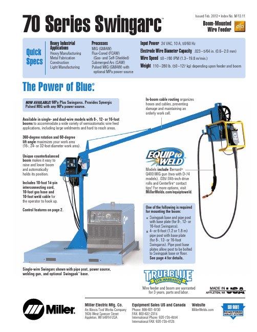
70 Series Swingarc™Boom-Mounted Wire FeederIssued Feb. 2012 • Index No. M/13.11The Power of Blue ®.Wire feeder and boom are warrantedAvailable in single- and dual-wire models with 8-, 12- or 16-foot booms to accommodate a wide variety of semiautomatic wire feed applications, including large weldments and hard to reach areas. 360-degree rotation and 60-degree lift angle maximizes your work area (16-, 24- or 32-foot diameter work area).Unique counterbalanced boom makes it easy to raise and lower boom and automatically holds its position.In-boom cable routing organizes hoses and cables, preventing damage and maintaining an orderly work cell.Includes 10-foot 14-pin interconnecting cord, 10-foot gas hose and 10-foot weld cable for the operator to hook up.Models include Bernard ®Q400 MIG gun (two with D-74models), .035/.045-inch drive rolls and Centerfire ™contact tips! For more options, visit /equiptoweld .Control features on page 2.Single-wire Swingarc shown with pipe post, power source,welding gun, and optional Swingpak ™base.One of the following is required for mounting the boom:Swingpak base and pipe post with base plate (for 8-, 12- or 16-foot Swingarcs).4- or 6-foot (1.2 or 1.8 m) pipe post with base plate (for 8-, 12- or 16-footSwingarcs). Pipe post base plates allow post to be bolted to Swingpak base or floor.See page 4 for details.Miller Electric Mfg. Co.An Illinois Tool Works Company 1635 West Spencer Street Appleton, WI 54914 USAWebsiteEquipment Sales US and CanadaPhone: 866-931-9730FAX: 800-637-2315International Phone: 920-735-4554International FAX: 920-735-4125NOW AVAILABLE! MPa Plus Swingarcs. Provides Synergic Pulsed MIG with any MPa power source.2MPa Plus Models Additional Features Alumination ™technology allows you to use the extended reach of a push-pull system for consistent, versatile and dependable aluminum wire feeding. Alumination gives you the versatility to handle whatever aluminum welding job you want to tackle.Synergic Pulsed MIG operation when optimized with MPa power supplies.Provides communication between the power source, feeder and gun. As wire speed increases/decreases, the pulseparameters also increase/decrease to match the right amount of power needed.Trigger schedule select allows the operator to select the alternative schedule by quickly tapping the gun trigger when not welding.When optimized with MPa power supplies the operator can also switch from MIG to Pulsed MIG.Profile Pulse ™provides TIG appearance with MIG simplicity andproductivity.Achieve “stacked dime” weld bead appearance without back-stepping. Profile Pulse frequency can be changed to increase or decrease the spacing between the ripple pattern to achieve the desired weld appearance.Accu-Mate ™properly seats the power pin for best feeding performance and prevents Accu-Mate grooved MIG guns from sliding in the casting.Models74S: Standard74D: Digital meters and remote voltage control 74DX: Deluxe —digital full feature74 MPa Plus: Digital full feature with Alumination ™technologyNote: 70 Series feeders are shown, but front panels are the same for both feeders and controls.70 Series Control FeaturesS-74DS-74DXS-74 MPa PlusS Models (Basic 70 Series feeders)Wire speed control .Factory-set run-in control for improved arc starts.24 VDC high-torque, permanent-magnet motor .Quick-change drive rolls .Quick-release, drive-roll pressure adjustment arm allows drive roll change without losing spring preload setting.Solid-state speed control and brake circuit for increased service life.Floating positive drive systems provide trouble-free feeding on a variety of wires.D Models Additional FeaturesDigital meters for easy viewing of the wire feed speed and voltage.Remote voltage control allows operator to set voltage at the wire feeder without having to go back to the power source.Tachometer feedback to help keep wire feed speed accurate.DX Models Additional FeaturesFour weld programs allow the operators to store four independent welding parameters reducing welding setup time. (Four programs available per side on dual feeder.)Adjustable run-in control for improved arc starts.Adjustable weld sequence control gives operator complete control of the welding parameters: preflow, run-in, weld time, crater, burnback and postflow.Welding process range control locks parameters at a set percentage of welding parameters to ensure welding proce d ures and quality standards are maintained on the shop floor .Dual schedule, trigger dual schedule and trigger program select allows operator to switch welding parameters without readjusting machine, eliminating downtime and enhancing quality.*Contact Miller Electric Mfg. Co. at 1-920-735-4505 for more information on optional low- and high-speed motor options.3Control Panels1.Program Display2.Program # Select3.Weld Sequence4.Voltage/Time Select5.Voltage/Time Display Meter6.Wire Feed/Amperage Select7.Wire Speed/Amperage Display Meter 8.Control Knob9.Trigger Hold/Dual Schedule Control 10.Jog/Purge1.Voltage Display Meter (S-74D model only)2.Wire Speed Display Meter (S-74D model only)3.Wire Feed Speed Select4.Trigger Hold5.Voltage Select6.Jog/Purge312654SS-74S and SS-74D Model1.Left Dual Schedule Indicator2.Voltage/Arc Length Display Meter3.Left Adjust Knob4.Setup Button5.Start Button6.Right Dual Schedule Indicator7.Amperage/Wire Speed Display Meter 8.Right Adjust Knob9.Left/Right Select Button 10.Crater Button 11.Jog/PurgeDS-74 MPa Plus ModelSS-74DX Model689107114Swingpak ™BaseFor use with 8-, 12- or 16-foot (2.4, 3.7 or 4.9 m) Swingarcs.Each base accommodates a power source, Swingarc feeder system, water coolant system, and gas cylinder. The base plate is solid to help better organize components and cables.The entire unit can be moved with a forklift truck.Note: Base must be mounted to floor with 16-foot Swingarc.S w i ng a r Pipe Post, requiredMIG GunPower Source, requiredOptional Swingpak BaseSpecifications and Usage (Subject to change without notice.)Model Swingpak Base 4-ft. Pipe Post with Base 6-ft. Pipe Post with BaseStock No.#183 997#149 838#149 839Dimensions L: 65 in. (1.7 m)W: 50.875in.(1.3 m)H: 4 ft. (1.2 m)H: 6 ft. (1.8 m)Net Weight 285 lb. (129 kg)110 lb. (49.9 kg)130 lb. (59 kg)Usage For 8-, 12- or 16-ft. SwingarcMounting Equipment for Swingarc ™Booms#151 026#243 233#151 052#161 190Drive Roll Kits and Guides (Order from Miller Service Parts.)Select drive roll kits from chart below according to type and wire size being used. Drive roll kits include four drive rolls, necessary guides and feature an anti-wear sleeve for inlet guide.*Accommodates .045- and .047-inch (3/64-inch) wire.“V” groove for hard wire“U” groove for “U” groove for wires contains “V” knurled for hard-shelled Nylon Wire Guides for Feeding Aluminum WireNote: “U” groove drive rolls are recommended when feeding aluminum wire.Wire Guidesfor extremely soft wire or soft-shelled cored wires (i.e., hard-facing types)Genuine Miller®Options and Accessories Remote Voltage Control#194 988 Field. Non-digital for S-74S#194 991 Field. Non-digital for D-74SConversion Kit#194 989 Field. S-74S to S-74D#194 992 Field. D-74S to D-74DSingle/Dual Spool Carrier(Pipe Post not included)#300 353 For use with 4-foot pipe#300 352 For use with 6-foot pipeSpool Covers#057 607For S-74 and left sideof D-74 models#090 389For right side ofD-74 modelsFor 12-inch (305 mm) spool.Note: Spool Covers cannot be installed if the wire drive assembly is in a rotated position.Wire Reel Assembly#108 008For 60-pound (27 kg)coil of wire.Reel Covers#195 412 For S-74 and left side ofD-74 models#091 668 For right side of D-74 models For 60-pound (27 kg) coil. Helps to protect the welding wire from dust and other contaminants.Note: Reel Covers cannot be installed if the wire drive assembly is in a rotated position.Spool Adapter #047 141For use with 14-pound (6.4 kg) spool of Lincoln self-shielding wire.Extension Cables for 14-Pin Plugs to14-Pin Sockets*#242 208 02525 ft. (7.6 m)#242 208 05050 ft. (15.2 m)#242 208 08080 ft. (24.4 m)Provides 14-pin, 24 VAC, contactor and voltage control. Add to the standard10-foot (3 m) feeder cable to extend feeder farther from power source.*Custom lengths available in 5-foot increments up to 50 feet and 10-foot increments up to 100 feet.Industrial MIG 4/0 Kit with DinseConnectors #300 405Includes Smith®flowmeter/regulator with10-foot (3 m) gas hose, 10-foot (3 m)4/0 feeder weld cable with Dinse connectoron one end and a lug on the other, 15-foot(4.6 m) work cable with Dinse connector onone end and 600-amp C-clamp on the other.Industrial MIG 4/0 Kit #300 390Includes the same as the kit above, exceptweld and work cables have lugs instead ofDinse connectors.Dual Schedule SwitchesDSS-8 #079 693A two-position trigger switch whichattaches to the gun handle and is used inplace of the standard trigger for dualscheduling. (For 74DX models only.)DSS-9 #071 833A two-position slide switch which attachesto the gun handle and is used to select thedesired welding condition for dual schedulepurposes. The gun trigger operates as a stan -dard gun trigger. (For 74DX models only.)For MPa Plus Wire Feeders onlyExtension Cables*#247 831 02525 ft. (7.6 m)#247 831 05050 ft. (15.2 m)#247 831 08080 ft. (24.4 m)Eleven conductors to support contactorcontrol and remote voltage control on allMiller electronic CV 14-pin power sources.Additional functions supported when usingthe MPa power sources include SynergicPulsed MIG, and remote process select andside select capabilities.*Custom lengths available in 5-foot increments up to50 feet and 10-foot increments up to 100 feet.XR-Aluma-Pro™Plus Gun#300 000 001 15 ft. (4.6 m), air-cooled#300 001 001 25 ft. (7.6 m), air-cooled#300 264 00135 ft. (10.6 m), air-cooled#300 003 001 15 ft. (4.6 m), water-cooled#300 004 001 25 ft. (7.6 m), water-cooled#300 265 00135 ft. (10.6 m), water-cooledThis easy-to-use and easy-to-maintaingooseneck-style MIG gun is designed forpush-pull wire feed systems. Available inair- or water-cooled versions. Trigger holdreduces operator fatigue. Gun designallows for better access into tight spots.1/16-inch (1.6 mm) Wire Kit#230 708Specially designed kit required whenrunning 1/16-inch wires on XR-Aluma-ProPlus gun.Includes idler roll, head tubeliner and inlet guide. Not included withstandard XR-Aluma-Pro Plus gun.Hardwire Liner Kit for Steel and Stainless#198 377For 15-, 25-, or 35-foot(4.6, 7.6 or 10.6 m) gunsKit consists of gun head tube liner andfeed cable liner. Recommend using.030–.045 inch mild steel or stainless steelelectrode wire (.052- and 1/16-inch wirenot recommended).Phosphorous Bronze Liner (Optional)#233 999Long Head Tube (air or water)#233 998Short Head Tube (air only)Steel Liner (Optional)#242 191Short Head Tube (air only)510-foot (3 m) interconnecting cord*When using the D model with Miller®power sources that DO NOT have remote voltage control capabilities, i.e., CP type, the voltage control in the feeder IS NOT functional. See Operator’s Manual for operating instructions. **If using the 70 Series feeders with a power source having only 115 VAC supply, the PSA-2 (Power Source Adapter) is required. When using the PSA control, optional remote voltage is not functional. See Operator’s Manual for operating instructions.Typical InstallationsModels74S: Standard74D: Digital meters and remote voltage control74DX: Deluxe—digital full feature74 MPa Plus: Digital full feature with Alumination™technology67Aluminum Gun Kits(for pushing aluminum wire)#300 541 10 ft. (3 m), .035 in. (0.9 mm)#300 54212 ft. (3.7 m), .047 in. (1.19 mm)#300 54312 ft. (3.7 m), 1/16 in. (1.6 mm)Includes .035-, .047-, or 1/16-inch drive rolls and10- or 12-foot Bernard ®Q-Gun.™Power Pin Tips#2200105 Plastic, .030–.035 in.(0.8–0.9 mm), for aluminum (red)#2200106 Plastic, .040–3/64 in.(1.02–1.19 mm), for aluminum (white)#2200107 Plastic, .052–1/16 in.(1.4–1.6 mm), for aluminum (blue)#4477*Brass, .023–.045 in.(0.6–1.2 mm), for steel#4477-564 Brass, .052–5/64 in.(1.01–2.0 mm), for steel Liners#44115*15 ft. (4.6 m),.035–.045 in. (0.9–1.2 mm), steel #44215 15 ft. (4.6 m),.045–1/16 in. (1.2–1.6 mm), steelT Series Centerfire ™Contact Tips 1.5 in. (38.1 mm)#T-023.023 in. (0.6 mm)#T-030.030 in. (0.8 mm)#T-035.035 in. (0.9 mm)#T-039.039 in. (1.0 mm)#T-045*.045 in. (1.2 mm)#T-052.052 in. (1.4 mm)#T-0621/16 in. (1.6 mm)#T-0785/64 in. (2.0 mm)#T-0943/32 in. (2.4 mm)#T-1097/64 in. (2.8 mm)#T-1251/8 in. (3.2 mm)TT Series Centerfire ™Contact Tips 2 in. (50.8 mm)#TT-023.023 in. (0.6 mm)#TT-030.030 in. (0.8 mm)#TT-035.035 in. (0.9 mm)#TT-039.039 in. (1.0 mm)#TT-045.045 in. (1.2 mm)#TT-052.052 in. (1.4 mm)#TT-0621/16 in. (1.6 mm)Centerfire ™Large Nozzles #N-3400C Copper, 3/4-in. I.D.,flush tip#N-3418C Copper, 3/4-in. I.D., 1/8-in. tip recess#N-3414C Copper, 3/4-in. I.D., 1/4-in. tip recess#N-3418B Brass, 3/4-in. I.D., 1/8-in. tip recess#N-3414B Brass, 3/4-in. I.D., 1/4-in. tip recess#N-5800C Copper, 5/8-in. I.D.,flush tip#N-5818C Copper, 5/8-in. I.D., 1/8-in. tip recess#N-5814C *Copper, 5/8-in. I.D., 1/4-in. tip recess#N-5818B Brass, 5/8-in. I.D., 1/8-in. tip recess#N-5814B Brass, 5/8-in. I.D., 1/4-in. tip recess Diffuser#D-1*Insulator #10012*Centerfire ™Small Nozzles #NS-5818C Copper, 5/8-in. I.D.,1/8-in. tip recess#NS-5800B Brass, 5/8-in. I.D.,flush tip#NS-5818B Brass, 5/8-in. I.D., 1/8-in. tip recess#NS-1218C Copper, 1/2-in. I.D., 1/8-in. tip recess#NS-1200B Brass, 1/2-in. I.D.,flush tip#NS-1218B Brass, 1/2-in. I.D., 1/8-in. tip recess#NST-3800B Brass, tapered, 3/8-in. I.D., flush tip#NST-3818B Brass, tapered, 3/8-in. I.D., 1/8-in. tip recess #NST-38XTB Brass, tapered, 3/8-in. I.D., 1/8-in. tip extension Diffuser#DS-1Insulator #4323RLarge Nozzle(see chart)“T” Series Tip(see chart)Diffuser#D-1Insulator#100123/4-in. I.D.5/8-in. I.D.Small Nozzle(see chart)“T” Series Tip(see chart)“TT” Series Tip(see chart)Diffuser#DS-1Insulator#4323R5/8-in. I.D.1/2-in. I.D.3/8-in. I.D.Tapered TipBernard ®Q ™-Series MIG Guns and Centerfire ™ConsumablesComposite insulator withstands heat andabuse and extends life. Centerfire ™consumables improve weld quality, reduce downtime and boost gun performance.Q-Series guns increase productivity, reduce downtime, and lower maintenance and inventory costs.Threaded nozzles keep contact tips centered and fixed at desired position for better weld placement and less spatter.Contact tips drop into gas diffuser and are locked in place by hand tightening the nozzle. Tapered base and large diameter seat increase electrical conductivity and heat dissipation.Built-in spatter shield protects diffuser and improves gas flow.Diffuser mates securely with contact tip for better conductivity.Integrated power pin properly seats the gun for optimal feeding and provides a locking Accu-Mate ™connection for the 74 Series feeder.Power pin tip eliminates gap between feeder guides and gun liner and comes in brass (hard wire) or plastic (soft wire).360-degree rotatable necks offer quick-change without tools.*Comes standard with Q400 15-ft. steel gun.Ordering InformationEquipment and Options Stock No.Description Qty.Price Single-Wire ModelsSS-74S8#951 2088 ft. With S-74S wire feeder, 15-ft. (4.6 m) Bernard Q400 gun and drive rollsSS-74S12#951 20912 ft. With S-74S wire feeder, 15-ft. (4.6 m) Bernard Q400 gun and drive rollsSS-74S16#951 21016 ft. With S-74S wire feeder, 15-ft. (4.6 m) Bernard Q400 gun and drive rollsSS-74D8#951 2118 ft. With S-74D wire feeder, 15-ft. (4.6 m) Bernard Q400 gun and drive rollsSS-74D12#951 21212 ft. With S-74D wire feeder, 15-ft. (4.6 m) Bernard Q400 gun and drive rollsSS-74D16#951 21316 ft. With S-74D wire feeder, 15-ft. (4.6 m) Bernard Q400 gun and drive rollsSS-74DX8#951 2148 ft. With S-74DX wire feeder, 15-ft. (4.6 m) Bernard Q400 gun and drive rollsSS-74DX12#951 21512 ft. With S-74DX wire feeder, 15-ft. (4.6 m) Bernard Q400 gun and drive rollsSS-74DX16#951 21616 ft. With S-74DX wire feeder, 15-ft. (4.6 m) Bernard Q400 gun and drive rollsSS-74MPa Plus-8#951 4378 ft. With S-74 MPa Plus wire feeder, 15-ft. (4.6 m) Bernard Q400 gun and drive rollsSS-74MPa Plus-12#951 43812 ft. With S-74 MPa Plus wire feeder, 15-ft. (4.6 m) Bernard Q400 gun and drive rollsSS-74MPa Plus-16#951 43916 ft. With S-74 MPa Plus wire feeder, 15-ft. (4.6 m) Bernard Q400 gun and drive rollsDual-Wire ModelsDS-74S8#951 2178 ft. With D-74S wire feeder, 15-ft. (4.6 m) Bernard Q400 gun and drive rollsDS-74S12#951 21812 ft. With D-74S wire feeder, 15-ft. (4.6 m) Bernard Q400 gun and drive rollsDS-74S16#951 21916 ft. With D-74S wire feeder, 15-ft. (4.6 m) Bernard Q400 gun and drive rollsDS-74D8#951 2208 ft. With D-74D wire feeder, 15-ft. (4.6 m) Bernard Q400 gun and drive rollsDS-74D12#951 22112 ft. With D-74D wire feeder, 15-ft. (4.6 m) Bernard Q400 gun and drive rollsDS-74D16#951 22216 ft. With D-74D wire feeder, 15-ft. (4.6 m) Bernard Q400 gun and drive rollsDS-74DX8#951 2238 ft. With D-74DX wire feeder, 15-ft. (4.6 m) Bernard Q400 gun and drive rollsDS-74DX12#951 22412 ft. With D-74DX wire feeder, 15-ft. (4.6 m) Bernard Q400 gun and drive rollsDS-74DX16#951 22516 ft. With D-74DX wire feeder, 15-ft. (4.6 m) Bernard Q400 gun and drive rollsDS-74MPa Plus-8#951 4408 ft. With D-74 MPa Plus wire feeder, 15-ft. (4.6 m) Bernard Q400 gun and drive rollsDS-74MPa Plus-12#951 44112 ft. With D-74 MPa Plus wire feeder, 15-ft. (4.6 m) Bernard Q400 gun and drive rollsDS-74MPa Plus-16#951 44216 ft. With D-74 MPa Plus wire feeder, 15-ft. (4.6 m) Bernard Q400 gun and drive rollsControl OptionsRemote Voltage Control#194 988Field. Non-digital control (S-74S model only)#194 991Field. Non-digital control (D-74S model only)Conversion Kit#194 989Field. S-74S to S-74D#194 992Field. D-74S to D-74DReplacement Gun and ConsumablesBernard®Q400#Q4015AE8EM400 A, 15 ft. (4.6 m)XR-Aluma-Pro™Plus For MPa Plus wire feeders only. See page 5Centerfire™Consumables See page 7Power SourcesInvision™352 MPa and 450 MPa See Lit. Index No. DC/23.6Deltaweld®Series See Lit. Index No. DC/16.2XMT®Series See Lit. Index No. DC/18.8 and 18.83XMT®MPa Series See Lit. Index No. DC/18.84Dimension™Series See Lit. Index No. DC/19.2Mounting EquipmentSwingpak™Base #183 997For 8-, 12- or 16-ft. boomsPipe Posts#149 8384-ft. with base for 8-, 12- or 16-ft. boom#149 8396-ft. with base for 8-, 12- or 16-ft. boomAccessoriesSingle/Dual Spool Carrier See page 5Spool Covers See page 5Wire Reel Assembly#108 008Reel Covers See page 5Spool Adapter#047 141Extension Cables See page 5Industrial MIG 4/0 Kit #300 405With Dinse connectors. See page 5#300 390With lugs. See page 5Dual Schedule Switches See page 5Date:Total Quoted Price:Distributed by:Litho in USA。
VarioStar 1500焊机说明书

VarioStar 1500/ 2500/3100操作说明书配件明细MIG/MAG焊机尊敬用户介绍非常感谢您选择福尼斯(Fronius),祝贺您购买福尼斯(Fronius)生产的新技术的高端产品!本操作手册将帮助您更好地使用新设备。
仔细地研读本手册,您很快会熟知福尼斯(Fronius)产品具有的许多强大功能,将真正体现出您采购本设备的最大优势。
敬请注意专用安全规则,并遵守!这样将确保使用中更安全。
当然,要仔细善待您的产品,可延长产品使用寿命和可靠性-也是体现最佳优势的基本要求。
安全规则危险!表示紧急危险情况,如不避免,将导致死亡或严重伤害。
此标志限于许多极度境遇,不用于物品损害,除非有人员伤害卷入的情况警告!表示潜在的危险情况,不避免,能导致死亡或严重伤害。
此标志不用于物品损害,除非有人员伤害卷入的情况。
小心!表示潜在的危险情况,不避免,可能导致次要或中度伤害。
此标志也用来警惕可引起物品损坏类的不安全行为。
注意!表示存在能影响焊接效果和设备损坏的风险的情况重要!表示实用经验提示和其他有用的特殊功能,不是有害和危险的标志。
上面出现的符号,必须更加注意相关内容!概述本设备是依照技术水准、符合所有安全规范生产。
不过,非法操作或滥用仍然会导致如下危险:——使用人员或他人的生命安全及安康——设备及用户/使用者的其他物品——设备工作效能任何启动、操作、维修及维护本设备的人员必须具备:——相应资质——熟知焊接——理解并正确执行本手册使用说明操作手册必须随时保留在设备所在场所。
除操作手册之外,常规可用的、当地事故预防和环境保护规则的复件必须能随时查到,当然也要实际遵守。
设备上的所有安全说明、危险和警告——必须保持清晰易读——不允许损坏和擦除——不允许遮掩、糊住或涂画设备上的安全说明、危险和警告,可参阅机器操作手册前部的“一般说明”任何可能影响机器安全的故障必须立即解决,然后才能给设备上电。
注意安全!限定用途设备仅可用来进行“约定用途”的工作。
火花机说明书

火花机操作说明书一.对机台的认识与了解现状在使用的火花机的规格为亚特M30E,M50E,M30F,M50F几种放电加工机。
放电机属精密加工机台,为达到良好的使用效果,必须先对机台的特性作一个了解认识.Ps:使用时特别要注意电极最大重量,最大工作台承重此两参数值,如所使用电极重量超过最大值或工件的重量超过最大工作台承重时千万不能使用此机台,否则将造成机台本身的零部件损坏.二.机台的零件编号及部份部件的作用:现状在使用的亚特火花机分E型和F型,E型放电机又称为传统式放电加工机,其特点是在使用的操作面板采用的旋钮式。
F型放电机又称可程序放电加工机,其特点是可以一次性输入多个单节加工条件和深度值,在操作火花机前首先要对机台的部件名称和作用作了解.现在以M30F和M50F两种机型来介绍(M30E和M50E机台的结构同F型,其主要区别在于操作面板的不同).现将各部件名称和作用列入表中参考三.机台的维护与保养3.1机台工作平台必须保证平整,需每月校正一次,.如磁台平面度不在0.005以内,则需研磨平台修整,重新校正;3.2机台无生锈现象,保持机身干凈,无油污;3.3观察压力表的读数是否正常(0.7~1.0kg/cm2),马达帮浦的转向是否同箭头方向保持一致(若相反也是压力表读数偏小的原因);3.4如图一中(A)的指示的部位—手动注油器,为导轨和方螺纹注入润滑油.保证机台良好的润滑性.随时注意注油器油标的高低,及时加油,如机台使用频繁应保证每天注油次数最少2次;3.5每周观察火花油槽内之油量,有无低于标准值,若低于标准值应及时加油;3.6如图二中绝缘液的清洁与更换:先将机台油桶内的油抽至一干凈桶内,抽至不能再抽时将图中(1)螺钉旋开,将油放入盒子中,待放完后再将(2)大螺钉松开,将(3)退开后将过滤蕊(4)拉出,将蕊桶擦拭干凈后换上新过滤蕊,密封好后换上新油(或待原油完全澄清后再倒回机台内);3.7机台三级保养:一级保养: (1)每天保证机台无油污、积尘等现象;(每天)(2)机台不用时保证各部件无生锈现象;(3)导轨每天按时上油,保证正常作业.二级保养: (1)定期检查油路是否畅通;(每月)(2)定期检查机台工作平面水平度;(3)定期添加机台导轨油;(4)定期检查各部件有无损坏.三级保养: (1)更换新的火花油;(每年) (2)更换机台工作平台.四.机台X、Y、Z三轴精度校正及磁台平面度校正4.1 X、Y、Z三轴精度校正(读数)将机台X(或Y)辆方向校正一平面度较好的挡块,固定于平台上,利用50mm、100mm、150mm、200mm的标准块规,将块规的一端紧贴挡块的校正面,然后用校表(千分表)使表针指向一固定读数(如40处),重复多次,看显示器读数是否相同,若几次都相同,再将显示器该轴的读数归零,然后校表保持绝对不动,将校表移至块规的另一端,用同一个点碰块规另一端,重复几次,看显示器的读数是否相同.读数若大于或小于该块规的寸法则表示该轴的读数精度不准确(视差值大小而论,若差值较大则应整修机台).Z轴是将块规置于平台上(平台要求平面度较好),用上述同样的方法观察其读数,视读数差值的大小而论是否应调整机台.4.2 X、Y、Z三轴垂直度校正保证磁台平面度的前提下,将一标准的垂直度校正器置于平台上,将校正器的一边校正平行,再检查与之垂直的另一边,若读数不相同,则表示该机台X、Y轴之间存在一定的夹角(不垂直),视差值大小考虑调整机台.Z轴同上,若已保证磁台平面度,而校正Z轴时出现差值,则应视差值大小考虑修整机台.五.操作面板说明5.1 E型火花机操作面板认识六.操作步骤6.1 E型操作步骤说明:6.1.1打开电源总开关,使用“REF”键使机台回复至工作坐标状态;6.1.2将平台整理平整、干凈;6.1.3将工件放于平台上校正并吸磁固定;6.1.4将电极按图纸相应的形状、方向装夹于机床夹头上,并校正电极;6.1.5寻电极X、Y方向之中心点:调整条件为OA(20~45)us;6.1.6选择极性:电极为正、工件为负;6.1.7寻边(分中方式)a.首先用电极M边寻工件CDEF面按“O”、“ENT”归零,同时连续按“L”、“ENT”使分中键作用;b.然后用电极N边寻工件CDEF面,得电极直径Φ(方法:用垫块紧贴工件CDEF面,电极N边碰垫块与CDEF面紧贴的面),(PS:此时垫块一定要贴紧工件的面,否则寻边出来的结果是错误的).按“ENT”使电极分中,找出电极此方中心,与CDEF面重合;c.用同样的方法寻出与ABDC边相重合的电极中心,此时当坐标移至(0.0)时,电极中心与工件基准点重合;d.用电极最高点寻工件ACEG面设放电深度Z(按实际尺寸设置).(PS:设值时当电流小于或等于3A时应用所需的定位电流“放电最后所要求的条件”设置深度,并且至细放预留量时应将工件和电极擦拭干凈重设一次深度,否则由于电极表面附碳的原因会使深度加工过深);e.将坐标移至(a、b)位置,选择适当的放电条件、冲油、放电.6.2 F型操作步骤说明6.2.1打开电源总开关,并按下旁边的红色按钮,待荧幕上出现画面(参数表); 6.2.2将平台整理平整干凈;6.2.3将工件置于平台上校正并吸磁固定;6.2.4参照图纸和放电指示单将电极按正确的形状及方向装夹于机头夹头上,并校正电极;6.2.5设定好寻边条件OA(20~45)us,按要求的寻边方式寻边;6.2.6选择极性:电极(正)、工件(负);6.2.7寻边(分中)a.首先用电极M边寻工件CDEF面按“←”将游标移至X处再依次按“X”、“O”、“ENT”;将此边零点找出;b.然后用电极N边寻工件CDEF面,得电极直径Φ(方法:用垫块紧贴工件CDEF面,电极N边碰垫块与CDEF面紧贴的面)按“1/2”、“ENT”使电极分中,找出电极此方中心与CDEF面重合;c.用同样的方法寻出与ABDC边相重合的电极中心,此时当坐标移至(0.0)时,电极中心与工件基准点重合;d.深度的设置(分两种方法:手动和自动)(1)手动:先将电极移至距要求设深度的工件表面2mm左右,再按放电开关,使工件和电极完全接触时(停止放电蜂呜器发出响声时),利用7.1的方式将游标移至Z处再依次按“Z”、“所需设置的深度值”、“ENT”设置完成深度,此时提升为“-”,下降为“+”(2)自动:先将电极移至距工件设深度表面2mm处.再将游标移至“”处,按“INC”(或DEC),使之设置为ON,再按“ENT”.开始设置深度.当听到电极和工件之间产生4次短路响后,机头自动提升5mm,将此面定为O面,然后在加工深度设定“Z DEPTH”.将游标移至对应的加工单节序号按“Z”、“所需加工深度值”“ENT”设置所需深度.此时若完工面高于0点;则应输入正值,若完工面低于0点,则应输入负值.且必须是上单节设置的深度数值大于下一单节,工作才会继续.(即提升为“+”;下降为“—”).e.将坐标移至(a.b)位置,选择适当的放电条件、冲油、放电.。
门型焊机使用说明书

目录一、特性、结构说明二、规范三、焊接前检查四、操作程序五、焊接时注意事项六、故障排除七、定期保养八、轨道安装一、本机特性1、自走式门型架、交直流自动埋弧电焊机、配备焊药回收系统、自动导弧装置。
2、适用于交、直流双弧双丝埋弧焊。
3、焊接形式为船形焊。
4、门架横梁上配有二套机头随动系统,伸缩住上下移动采用电控,整套系统左右定位采用手动。
5、由机械组成焊机头的导弧装置,焊接位置精确,故障率极低。
6、整个门架由两组交流电机连减速器驱动。
7、所有控制线,焊接电缆,软气管均以台车式传送。
8、焊药回收系统系一独立系统,容量为100KG。
9、配有紧急安全开关。
10、用类比型仪表显示焊接电压电流,用数字型仪表显示焊接速度,(门架移动速度)。
二、规范1、适用H型钢尺寸宽度: 200-800mm高度: 200-1200mm长度: 15000mm2、焊机: MZ-1-1000或MZ-1-12503、焊接位置:船型焊4、使用电源: 380V/50Hz5、速度控制:变频调速6、机台速度: 2936mm/min7、焊接速度: 250mm-750mm/min8、伸缩柱左右调整:手调试9、控制箱型式:固定式10、控制箱功能:焊接机/机台移动11、焊粉回收机: 100公斤容量12、电源位置:放置于台机中央13、轨道宽度: 4000mm14、机台总宽度: 4400mm15、焊接高度: 1200mm16、导弧装置:机械压迫式17、电缆输送:电缆台车18、适用焊线尺寸:Φ3.2-5mm19、线盘重量: 50-150kg三、焊接前检查1、轨道上是否有异物阻挡及平整。
2、焊粉量及流量是否足够及通畅。
3.电焊机电源及保险丝。
4、焊口清除焊口易附着水气、灰尘、油脂、焊渣及涂料,这些都是焊道废气的来源,使得焊接后,焊道产生脆化及气孔,因此必须清除干净。
6、开车检测焊丝焊粉是否通畅。
7、电缆台车是否有松动现象及其轨道是否有障碍物。
8、接地线及焊接电缆是否确实接紧,及有否烧毁现象。
PRO 750 WET SAW 零部件安全与操作手册说明书

Owner’s Safety and Operating ManualContentsSafety Instructions ...................................................3 Machine Specification & Electrical Requirements ......4 Assembly & Operating Instructions ......................5-6 Maintenance & Warranty .. (7)POWER PRO 750 Wet SawSafety InstructionsTo use this tool correctly, you must observe the Safety Regulations, theAssembly Instructions and the Operation Instructions contained in this Manual.All persons who use and service the machine must be acquainted with this Manual and must be informed about any potential hazards.Children and infirm people must not use this tool. Children must be supervised at all times if they are in the area in which the tool is being used.It is also imperative that you observe the accident prevention regulations in force in your area. The same applies for general rules of occupational health and safety.• Take suitable precautions to protect your eyes, ears, lungs and hands when operating the Wet Saw.• Keep children and others away from the machine whilst in use.• Only use circular blades with a continuous rim– DO NOT USEsegmented circular blades, saw blades or abrasive disks.• The machine should be used indoors only, in a clean, dry,well lit area and on a clutter free, flat work surface.• Avoid wearing loose clothing, ties,rings, bracelets or other loose items which may become caught in the moving parts. Long hair should also be tied back or contained.• Always ensure that all loose tools and components are removed from the immediate working area.• Switch machine off between cuts and disconnect from mains supply before carrying out any maintenance,cleaning or changing the blade.• Do not leave the saw runningunattended or touch the blade whilst in motion – always use the blade guard when cutting.• Replace damaged blades immediately and ensure that new blades are fitted correctly to run in the direction indicated on the blade.• Only recommended replacement parts should be used with this machine – use of improper accessories could cause serious injuryAutomatic Overload ProtectionTo prevent overheating this machine has automatic overload protection which is designed to cut power to the motor.Should the automatic overload protection trip, ensure that mains power supply and machine switch are turned off.After ten seconds press the breakerbutton next to the main switch and restart the machine.To fit or replace the Cutting Wheel, first take out the removable side of the cutting table. Remove nut and washer using the wrench providedPlace the Rip Guide on the preferred side of the table top and line up with the rule edge to the required measurement of the tile to be cut. When correctly aligned, lock in place by pushing the adjuster firmly downwards.Position the tile on the table top.Switch on the machine.Maintain an even pressure, hold the tile against the cutting guide and push steadily through the cutting wheel. When the cut is complete, switch off the machine.Straight CutsPosition blade against the black inner washer ensuring that the directional arrow on the blade matches that on the cutting table. Replace the washer and nut. Do not over tighten.Before replacing table top, fasten guard support in the slot behind the blade opening using the screws provided. Attach blade guard to the support using bolt and wing nut.Fill the reservoir to a point just below theoverflow opening at the top of the drain plug. Replace cutting table. Check frequently during use - do not allow the blade to run dry.• Repair or replace damaged or worn cable immediately after first disconnecting from • Electrical faults must only be rectified by aSlide the Mitre Guide into place on the Rip Guide.For Mitre cuts, raise the cutting table to therequired angle (15O, 30O or 45O degrees)Slacken the thumb screw and set the required angle of cut.Locate the appropriate lugs into the slots provided on the inside edge of the reservoir.Re-tighten the knob and position the tile withinthe jaws of the Mitre Guide.Place the tile against the angled table top.Switch on the machine and while holding the tile firmly in position, push the mitre guide steadily along the rip guide, feeding the tile through the cutting wheel. When the cut is complete, switch off the machine.Switch on the machine and feed the tile through the cutting wheel. When the cut is complete, switch off the machine.Angular Cuts Mitre Cuts。
TransSteel Pulse 焊接技术产品说明书
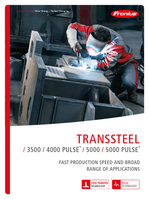
/ Perfect Welding / Solar Energy / Perfect Charging/ 2Yet the power source remains versatile: The TransSteel versions with the Pulse function make child's play of applications involving aluminium and stainless steel. SMEs can benefit from this variety of materials, as just one device is all they need to cover a wide range of applications. The underlying philosophy – stay on top of things. The function spectrum of the TransSteel has therefore been deliberately reduced to the essentials in all areas according to the motto - as much as necessary, with the best possible overview and ease of handling.HIGH-POWER WELDING AND A BROAD RANGE OF APPLICATIONS.WHETHER CONTAINER CONSTRUCTION, BRIDGE CONTRUCTION OR YELLOW GOODS:WITH NEARLY 170 OPTIMISED CHARACTERISTICS, THE TRANSSTEEL SERIES FEATURES THECHARACTERISTICS DEMANDED BY THE HEAVY-DUTY STEEL CONSTRUCTION SECTOR.Let’s get connec ted.What´s your welding challenge?70% LESS40%DUTY CYCLE/The Pulse function of the TransSteel 4000 and 5000 Pulse CUSTOMER BENEFITSREADY TO WELDIN THREE STEPS /The intuitive operating concept enables welders to start work straight away – no prior knowledge of the device is required. All the essential welding parameters can be viewed and adjusted on the front panel. The only parameters that have to be selected before welding begins are the gas, wire diameter and material thickness.167CHARACTERISTICS */Steel, CrNi, AlMg, AlSi, Metal Cored, Rutil FCW, Basic FCW, Self-shielded /0.8 – 1.6mm wire diameter /Eight different gas mixturesFour minutes of continuous welding at maximum output power, in other words, one minute more of productive output compared with the average in this power range.123ED40%/ 4THE TRANSSTEEL SERIESFUNCTIONS TransSteel3500TransSteel4000 PULSETransSteel5000TransSteel5000 PULSEPulseSynchroPulseData documentationMains operation3-phase3-phase3-phase3-phase Cooling Water-cooled Water-cooled Water-cooled Water-cooled Wire speed4R4R4R4REasy Jobs5555VERSATILE: FOR A BROAD RANGE OFAPPLICATIONS!/ 5To run repetitive welding tasks quickly and easily, five sets of welding parameters canbe saved – these are known as EasyJobs.THE REQUIRED WELDING PARAMETERS CAN THEN BE ACCESSED AT THE TOUCH OF A BUTTON.Entering a particular button combination locks the TransSteel control panel, MAKING UNINTENTIONAL MODIFICATIONS TO THE WELDING PARAMETERS IMPOSSIBLE. An optional keylock switch is also available for all the control panels in the TransSteel series (with the exception of TransSteel 2200 & 2700 C).CONTROL PANEL LOCKEASY JOBS/ 6The “SynchroPulse” option is recommended for the weldingof aluminium alloys when a rippled seam appearance isrequired. This effect is achieved by modifying the weldingSYNCHROPULSE works inSTANDARD SYNERGIC AND PULSE SYNERGIC MODE –but only on the TransSteel 4000 and 5000 Pulse./ 7CORRECTIONS / ARC LENGTH CORRECTION ARC-FORCE DYNAMIC / ARC LENGTH CORRECTIONTO CHANGE THE ARC CHARACTERISTICshorter arc, reduced welding voltage neutral arclonger arc, increased welding voltage/ ARC-FORCE DYNAMICsoft, low-spatter arc/ PULSE CORRECTIONhigher droplet detachment forceSuchen Sie nach den Icons in diesem Folder und erhalten Sie mit ihrer Magic Folder App weitere interessante Inhalte./ 8WELDING DATA DOCUMENTATIONWelding data documentation is essential, particularly in steel construction. Load-bearing steel structures, mass-produced products or sensitive parts often have to be traceable down to the final welding parameters. The Easy Documentation option enables TransSteel to record welding data extremely easily.USBTHUMB DRIVEEXPORT FUNCTIONA USB thumb drive can be connected to the rear of the device (the stick is included as part of the scope of supply with the Easy Documentation option). The drive can then be used to export a CSV file containing welding data.Easy Documentation records the following welding parameters:/Power source ID /Firmware version /Serial number/Process (Manual, Standard, Pulse, TIG, MMA)/Current / voltage / wire speed in the main process phase /Power from instantaneous values “IP” (Instantaneous Power) - energy / time (in the main process phase) /Energy from instantaneous values “IE” (Instantaneous Energy) over the entire welding operation /Motor current (in the main process phase)/Time stamp hh:mm:ss when current starts to flow /Counter/Welding duration/Error no. when welding is terminated /Wire speed (metric and imperial) /Characteristic number/Operating mode (2T, S2T, 4T, S4T, spot welding, stitch welding, SynchroPulse)/Signature for each weld seam number /Template for .csv file/Easy Job numberEASYDOCUMENTATIONRECORDING OF WELDING PARAMETERSThe Fronius central connector for all media and enables a variety of connected.FSCFRONIUS SYSTEM CONNECTORMORE THAN MULTILOCK:30 VERSIONS45°Suitable for all splitdevices in the TransSteel series.TU CAR 4TROLLEYBASIC, STANDARD & PROOPTIONS AVAILABLE IN THREEVERSIONSREMOTE CONTROLTR 1300/ 11The cooling unit is filled as standard with FCL10 coolant and is equipped with a coolant filter (and a flow temperature sensor as an option).COOLING UNITFK 5000A 4-roller wirefeeder with optional control unit for pulse or standardapplications that is perfectlyadapted to the systemVR 5000 REMOTETOOL BOXHANDY TOOL BOXSuitable for all split devices in the TransSteel series./ Perfect Welding / Solar Energy / Perfect ChargingT e x t a n d i m a g e s c o r r e s p o n d t o t h e c u r r e n t s t a t e o f t e c h n o l o g y a t t h e t i m e o f p r i n t i n g . S u b j e c t t o m o d i f i c a t i o n s .A l l i n f o r m a t i o n i s w i t h o u t g u a r a n t e e i n s p i t e o f c a r e f u l e d i t i n g - l i a b i l i t y e x c l u d e d . C o p y r i g h t © 2011 F r o n i u s ™. All r i g h t s r e s e r v e d .Further information about all Fronius products and our global sales partners and representatives can be found at THREE BUSINESS UNITS, ONE GOAL: TO SET THE STANDARD THROUGH TECHNOLOGICAL ADVANCEMENT.What began in 1945 as a one-man operation now sets technological standards in the fields of welding technology, photovoltaics and battery charging. Today, the company has around 5,440 employees worldwide and 1,264 patents for product development show the innovative spirit within the company. Sustainable development means for us to implement environmentally relevant and social aspects equally with economic factors. Our goal has remained constant throughout:to be the innovation leader.a w 21Fronius International GmbH Froniusplatz 14600 Wels AustriaTelephone +43 7242 241-0Fax +43 7242 241-953940*****************Fronius UK LimitedMaidstone Road, Kingston Milton Keynes, MK10 0BD United KingdomTelephone +44 1908 512 300Fax +44 1908 512 329*******************www.fronius.co.thE N v 01 A u g2020FOR MORE INFORMATIONabout TransSteel, visitREGISTER YOURPOWER SOURCEto extend your warrantyhttps:///pw/product-registrationTECHNICAL DATA。
全自动串焊机操作指导书

版次 页次
1:搬送部进入 2:溶着部进入 3: 右边焊带供给进入 4:左边焊带供给进入 5:右边焊带投入移栽进入 6左边焊带投入移栽进入,7:焊接溶着部进入 8:电池片供给一部进入 9:电池片供给2部进入 10:位置决定部进入 11助焊剂搬送部进入 12:电池片供给电机 13:搬送电机 14:分离汽缸 15:供给移栽 16:分离气阀 17:搬送移栽 18:投入移栽 19:助焊剂电磁阀 20:预热台 21:LED搬送 22:定位移栽(机械手) 23:检查部 24:搬送移栽 25:焊带放置台 26:焊带投入移栽 27:左热风管 28:左边焊针 29:传送带 30:左冷却 31:左焊接底板,32:右冷却 33:右焊接底板 34:右边焊针 在主界面上 按下手动操作进如手动操作界面,按下1进入 图三操作界面,按下2进入图二
1
图一
2
图二
34
6
7
5
图三
8 9 10
11
图四
12 13 14 1
15 16
1
1
THIS DOCUMENT IS THE SOLE PROPERTY OF JINKO SOLAR CO.,LTD. AND SHOULD NOT BE USED IN WHOLE OR IN PART WITHOUT PRIOR WRITTEN PERMISSION
本文件属晶科能源有限公司独有财产,未经书面许可不得使用或部分使用
晶科能源有限公司
Jinko Solar Co., Ltd.
文件名称:
文件编号
版次
全自动串焊机操作指导书
文件等级
页次
更换焊带流程:
1、 将使用完后的铜带轮取下,按hanuac mode(手动模式) 按下EXCHANGE MODE(交换模式 TAB HOLDER OPEN(切换支架开), 然后将相应的规格的铜带安装好,提起张力臂 压带轮打开 将铜带穿过 上导轮 张力臂 压带轮 裁切口 按HOMING(返回) TAB EXCHANGE CYCLE START(切换 循环开始)
CLASSIC III 线性电焊机操作手册说明书
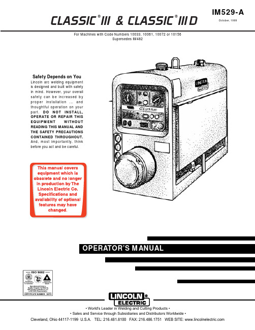
CLASSIC ®III & CLASSIC ®III DFor Machines with Code Numbers 10033, 10061, 10072 or 10156Supersedes IM482IM529-AOctober, 1999Safety Depends on YouLincoln arc welding equipment is designed and built with safety in mind. However, your overall safety can be increased by proper installation ... and thoughtful operation on your part.DO NOT INSTALL,OPERATE OR REPAIR THIS EQUIPMENT WITHOUT READING THIS MANUAL AND THE SAFETY PRECAUTIONS CONTAINED THROUGHOUT.And, most importantly, thinkbefore you act and be careful.Mar ‘95Mar. ‘93for selecting a QUALITY product by Lincoln Electric. We want you to take pride in operating this Lincoln Electric C ompany product ••• as much pride as we have in bringing this product to you!Read this Operators Manual completely before attempting to use this equipment. Save this manual and keep it handy for quick reference. Pay particular attention to the safety instructions we have provided for your protection.The level of seriousness to be applied to each is explained below:vvviTECHNICAL SPECIFICATIONS – CLASSIC III AND IIID Machine*Based on a 10 min. period.@Meets Canadian StandardsProduct Name Description Horsepower OperatingSpeedsDisplacement Ignition CapacitiesClassic III Classic III D4 Cylinder4 CycleWater-CooledGasoline EngineCast Iron Cylinder,Block/Crankcase4 Cylinder4 CycleWater-CooledDiesel EngineCast Iron Cylinder,Block/Crankcase45 HP@ 1700 RPM38.9 HP@ 1700 RPMFull Load:1725 RPMHigh Idle:1800 RPMLow Idle:1350 RPM164.7 Cu In(2.7 ltrs)Distributor TypeElectronicDieselFuel:15 Gals (57 Ltrs)Lubricating Oil:7.0 Qts (6.7 Ltrs)Coolant:9.3 Qts (8.8 Ltrs)EngineB AWire Feed Module (K623-1) - Provides constant voltage (C V) output with improved arc stability for Innershield welding. Excellent for MIG welding. Recommended wire feeders are the LN-7, LN-23P and LN-25. (Factory installed on the K1428-3 and K1433-2).NameplatesWhenever routine maintenance is performed on this machine - or at least yearly - inspect all nameplates and labels for legibility. Replace those which are no longer clear. Refer to the parts list for the replace-ment item number.I = Inspect C = Clean R = Replace NOTES:(1)Consult Engine Operators Manual for oil recommendations.(2)Or equivalent.(3)First inspection after 50 hours; every 500 thereafter.(4)Gasoline engine only.(5)Diesel engine only. (Welder Code Numbers 10061 and below)(6)Diesel engine only. (Welder Code Numbers above 10061)(7)Consult Engine Operators Manual for additional maintenance schedule information.5-6-94C S20919-1TROUBLESHOOTINGHave qualified personnel do the troubleshooting work. Turn the engine off before working inside the machine. In some cases, it may be neces-sary to remove safety guards to perform required maintenance. Remove guards only when necessary and replace them when the maintenance requiring their removal is com-plete. Always use the greatest care when work-ing near moving parts.Do not put your hands near the engine cooling blower fan. If a problem cannot be corrected by following the instructions, take the machine to the nearest Lincoln Field Service Shop.------------------------------------------------------------ELECTRIC SHOCK can kill.•Do not touch electrically live parts or electrode with skin or wet clothing.•Insulate yourself from work and ground• Always wear dry insulating gloves.EXHAUST can kill.Use in open, well ventilated areas or vent exhaust outside.------------------------------------------------------------------------MOVING PARTS can injure.•Do not operate with doors open or guards off.• Stop engine before servicing.• Keep away from moving parts.------------------------------------------------------------------------See additional warning information at the front of this operator’s manual------------------------------------------------------------(1)FLASHING THE FIELDS:1.Stop the engine welder and remove the cover from the exciter.2.Turn the “Fine Adjustment Control” (rheostat) to “100” on the dial.ing a 12 volt automotive battery, connect it’s negative terminal to the negative brushholder. Thenegative brushholder is the one nearest to the rotor lamination. See the wiring diagram. With theengine NOT running, touch the positive battery terminal to the positive brushholder. Remove thebattery from the circuit.4.Replace the exciter cover. Start the welder and the generator voltage should build up.ENGINE TROUBLESHOOTING - (TM27 Gasoline Engine Only)**See engine manual.L 9260C L A S S I C I I ID W I R I N G D I A G R A ME : T h i s d i a g r a m i s f o r r e f e r e n c e o n l y . I t m a y n o t b e a c c u r a t e f o r a l l m a c h i n e s c o v e r e d b y t h i s m a n u a l . T h e s p e c i f i c d i a g r a m f o r a p a r t i c u l a r c o d e i s p a s t e d i n s i d e a c h i n e o n o n e o f t h e e n c l o s u r e p a n e l s . I f t h e d i a g r a m i s i l l e g i b l e , w r i t e t o t h e S e r v i c e D e p a r t m e n t f o r a r e p l a c e m e n t . G i v e t h e e q u i p m e n t c o d e n u m b e r ..Now Available...12th EditionThe Procedure Handbook of Arc WeldingWith over 500,000 copies of previous editions published since 1933, the Procedure Handbook is considered by many to be the “Bible” of the arc welding industry.This printing will go fast so don’t delay. Place your order now using the coupon below.The hardbound book contains over 750 pages of welding information, techniques and procedures. Much of this material has never been included in any other book.A must for all welders, supervisors, engineers and designers. Many welding instructors will want to use the book as a reference for all students by taking advantage of the low quantity discount prices which include shipping by 4th class parcel post.$15.00postage paid U.S.A. MainlandHow To Read Shop DrawingsThe book contains the latest information and application data on the American Welding Society Standard Welding Symbols. Detailed discussion tells how engineers and draftsmen use the “short-cut” language of symbols to pass on assembly and welding information to shop personnel.Practical exercises and examples develop the reader’s ability to visualize mechanically drawn objects as they will appear in their assembled form.187 pages with more than 100 illustrations. Size 8-1/2” x 11”Durable, cloth-covered board binding.$4.50postage paid U.S.A. MainlandNew Lessons in Arc WeldingLessons, simply written, cover manipulatory techniques;machine and electrode characteristics; related subjects,such as distortion; and supplemental information on arc welding applications, speeds and costs. Practice materials,exercises, questions and answers are suggested for each lesson.528 pages, well illustrated, 6” x 9” size, bound in simulated,gold embossed leather.$5.00postage paid U.S.A. MainlandNeed Welding Training?The Lincoln Electric C ompany operates the oldest and most respected Arc Welding School in the United States at its corporate headquarters in C leveland, Ohio. Over 100,000stu-dents have graduated. Tuition is low and the training is “hands on”For details write:Lincoln Welding School 22801 St. Clair Ave.Cleveland, Ohio 44117-1199.and ask for bulletin ED-80 or call 216-383-2259 and ask for the Welding School Registrar.Lincoln Welding SchoolBASIC COURSE $700.005 weeks of fundamentalsThere is a 10%discount on all orders of $50.00 or more for shipment at one time to one location.Orders of $50 or less before discount or orders outside of North America must be prepaid with charge, check or money order in U.S. Funds Only.Prices include shipment by 4th Class Book Rate for U.S.A. Mainland Only.Please allow up to 4 weeks for delivery.UPS Shipping for North America Only.All prepaid orders that request UPS shipment please add:$5.00For order value up to $49.99$10.00For order value between $50.00 & $99.99$15.00For order value between $100.00 & $149.00For North America invoiced orders over $50.00 & credit card orders, if UPS is requested, it will be invoiced or charged to you at cost.Outside U.S.A. Mainland order must be prepaid in U.S. Funds. Please add $2.00 per book for surface mail or $15.00 per book for air parcel post shipment.METHOD OF PAYMENT:(Sorry, No C.O.D. Orders)CHECK ONE:Name:_______________________________________________Please Invoice (only if order is over $50.00)Address:_______________________________________________Check or Money Order Enclosed, U.S. Funds only _______________________________________________Credit Card - Telephone:_______________________________________________Signature as it appears on Charge Card:Account No.Exp Date|_|_||_|_|______________________Month YearUSE THIS FORM TO ORDER:Order from:BOOK DIVISION, The Lincoln Electric Company, 22801 St. Clair Avenue, Cleveland, Ohio 44117-1199BOOKS OR FREE INFORMATIVE CATALOGS Telephone: 216-383-2211 or, for fastest service, FAX this completed form to: 216-361-5901.Lincoln Welding School Titles:Price Code QuantityCost(ED-80)New Lessons in Arc Welding $5.00L Seminar Information Procedure Handbook “Twelfth Edition”$15.00PH (ED-45)How to Read Shop Drawings $4.50H Educational Video Information Incentive Management $5.00IM (ED-93) A New Approach to Industrial Economics $5.00NA James F. Lincoln Arc Welding The American Century of John C. Lincoln $5.00AC Foundation Book Information Welding Preheat Calculator $3.00WC-8(JFLF-515)Pipe Welding Charts $4.50ED-89SUB TOTALAdditional Shipping Costs if anyTOTAL COSTJapaneseChineseKoreanArabicREAD AND UNDERSTAND THE MANUFACTURER’S INSTRUCTION FOR THIS EQUIPMENT AND THE CONSUMABLES TO BE USED AND FOLLOW YOUR EMPLOYER’S SAFETY PRACTICES.SE RECOMIENDA LEER Y ENTENDER LAS INSTRUCCIONES DEL FABRICANTE PARA EL USO DE ESTE EQUIPO Y LOS CONSUMIBLES QUE VA A UTILIZAR, SIGA LAS MEDIDAS DE SEGURIDAD DE SU SUPERVISOR.LISEZ ET COMPRENEZ LES INSTRUCTIONS DU FABRICANT EN CE QUI REGARDE CET EQUIPMENT ET LES PRODUITS A ETRE EMPLOYES ET SUIVEZ LES PROCEDURES DE SECURITE DE VOTRE EMPLOYEUR.LESEN SIE UND BEFOLGEN SIE DIE BETRIEBSANLEITUNG DER ANLAGE UND DEN ELEKTRODENEINSATZ DES HER-STELLERS. DIE UNFALLVERHÜTUNGSVORSCHRIFTEN DES ARBEITGEBERS SIND EBENFALLS ZU BEACHTEN.JapaneseChineseKoreanArabicLEIA E COMPREENDA AS INSTRUÇÕES DO FABRICANTE PARA ESTE EQUIPAMENTO E AS PARTES DE USO, E SIGA AS PRÁTICAS DE SEGURANÇA DO EMPREGADOR.• Sales and Service through Subsidiaries and Distributors Worldwide •Cleveland, Ohio 44117-1199 U.S.A. TEL: 216.481.8100 FAX: 216.486.1751 WEB SITE: 。
金丝球焊接工艺
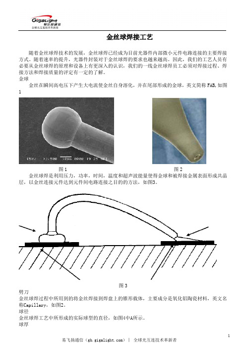
2
易飞扬通信()︱ 全球光互连技术革新者
图7-2 设备要求 a) 整机具有可靠接地系统; b) 超声时间:分级可调; c) 超声功率:分级可调; d) 焊接压力:分级可调; e) 烧球电流:分级可调; f) 烧球时间:分级可调; g) 烧球尾丝长度:可手动调整或分级可调; h) 焊接温度:0 –250℃可调; i) 显微镜:5‐50倍可调整,焦距可调整 工作环境:万级以上的无尘室。 金丝球焊机结构 按照设备功能来分可以分为:烧球系统、输线系统、加热系统、超声传导系统、目视系统、软硬 件操作系统。 烧球系统 球焊机利用打火杆产生的瞬间高电压溶化金丝形成金球。 输线系统 保证金丝与焊接面间的角度不变,每次出线的长度一致。 加热系统 为焊接提供温度保证。 超声传导系统 超声发生部件通过超声传导杆的作业将超声能量和压力传给劈刀,劈刀再作用于金球与焊盘上, 以形成有效焊接。 目视系统:
尾丝过长, 不合格 图20
焊点脱落 不允许有一焊点脱落或二焊点脱落的现象,如图21 所示。
球脱物
第一焊点和第二焊点的下面必须是完整的金属层,不允许焊在导电胶、焊料或是异物上。
重复焊接
不允许在同一处重复焊接。
拉力测试标准
拉力最小值与金线直径的对应关系,如表1
10
易飞扬通信()︱ 全球光互连技术革新者
金线不完全在球型上,不合格
金线完全在球型上,合格
图14
鱼尾宽度、长度和形状
1)鱼尾的宽度应该满足大于金线直径的1.2倍且小于金线直径的5倍。
2)鱼尾的长度应该满足大于金线直径的0.5倍且小于金线直径的3倍。
3)鱼尾压痕必须覆盖整个金线的宽度,如图15所示。
图15 线间距 1) 任何线与线之间的距离必须大于2 倍金丝直径; 2) 任何线与管芯、IC、陶瓷、电容的距离必须大于2 倍金丝直径,如图16 所示。
点焊机操作说明

半自动单点电池点焊机操作说明书(电气)OPERATION INSTRUCTIONS!使用前先详细阅读操作说明书或者在有专业技术人员指导下进行操作。
目录一安全防范1.1 安装安装点附近不要堆放易燃品。
否则,可能引起火灾。
搬运时一定要抓紧支撑部分。
否则,可能有跌倒损坏危险。
请防止外部异物进入到设备内部。
否则,可能引起短路。
请确保接地良好。
否则,可能引起电击或火灾。
布线必须由合格的电气专业人员作业。
否则,可能引起电击或火灾。
请确保安装空间有良好的通风条件,避免运行环境中有灰尘、腐蚀气体、易燃气体等。
避免安装空间有震动,不牢固。
否则,可能引起短路或损坏。
请确保电压、气源满足以下条件:电源1Φ+N AC220V,50/60Hz,3kW气源0.15~0.2Mpa1.2 操作断开输入电源超过10 分钟后,再进行维护和检查。
否则,有电击危险。
请确保由合格电气操作人员在经授权后进行维护、检查和更换零件。
否则有电击危险。
不要用湿手操作。
否则,有电击危险。
请确保接地良好。
否则,可能引起电击或火灾。
通电状态下不能接触设备内部配件。
否则,可能引起电击。
发热组件温度非常高,请不要触及。
否则,有烧伤的危险。
二安装使用条件2.1 安装条件2.2 使用环境三操作说明3.1 系统上电1)确认机台电源线、气源(空压机)电源线及米亚基焊接主机电源线已正确连接;2)确认机台断路器处于接通状态,且气源开关和米亚基焊接主机的电源开关处于ON状态;3)按下操作面板箱上的电源开关,并确认红色电源指示灯点亮;4)待操作面板箱上的触摸屏显示如图3.1所示的开机画面时,表示系统已上电完成。
3.2 系统初始化系统上电完成后,触摸屏会显示如图3.1所示的开机画面。
此时会显示机台当前状态为“等待初始化”状态,长按屏幕左下方的“一键复位”按钮1秒,待“一键复位”按钮显示为绿色黄色“复位中”时,机台开始初始化,即复位伺服电机位置及扫描焊接主机是否正常。
图3.1 系统开机画面系统初始化时,若没有接通焊接机电源,则会弹出如图3.2所示的米亚基初始化失败提示窗,如果是正常作业,则需要确认米亚基焊接主机是否已经正常供电;如果只是进行对位测试,则只需长按窗口右下方的“跳过自检”按钮直至窗口自动关闭为止即可。
TPS(奥地利福尼斯)焊机使用说明书
此类焊机为完全数字化的新型逆变焊机,它带有微 处理控制器。由它集中处理所有焊接数据,数字化 控制和监测整个焊接过程。并快速对任何焊接过程 的变化作出反应。由 Fronius 开发的数字化控制系 统,能确保实现理想的焊接效果。
供 400 安和 500 安的电流,应用广泛,能满足各种 苛刻的工业要求。他们的设计面向于汽车生产、模 具制造、化工领域、机器制造、以及造船业等。
改装焊机
如果没得到制造厂商的许可,最好不要对焊机 作任何的改装、安装附件及修改。 及时换下不合格的元件。
备用件和易损件 使用 Fronius 厂的原装备用件和易损件。那些其 它厂家的元件,无法确定他们是否能满足那些 特殊设计要求及其它耐压、安全方面的性能。 在定购备用件时,请注明确切的名称和相关的 零件号,在备件表中给以特定的说明。同时, 请提供焊机的机身号。
控制面板(Standard). 控制面板(Comfort)
“方法”参数 ……………………………42
普通/脉冲 MIG/MAG 焊 TIG 焊
2
手工电弧焊
参数“模式”-----------------------------------43
专为机器人设计的特殊 2 步模式 焊铝的特殊特殊四步 模式 丝机齿轮旁边。 对有火花敏感的场合,操作时必须另外申请一 块专用的焊接场所。 只 有 通 过 安 全 认 证 ,焊 机 才 可 用 于 高 压 电 场 合 。
4
有特殊安全要求的设备,其焊接工作必须由受 过专业培训的焊工来完成。 当 由 起 重 机 吊 起 焊 机 时 ,为 了 尽 可 能 垂 直 起 吊 , 一般用锁链或绳索辅助。在吊起之前,相应地 移动气瓶和送丝机。 用起重机吊起送丝机时,一般用有间隔的悬挂 排列。
手动金丝球焊机说明书

HKD-2320TS超声波金丝球焊机使用说明书目录1.概述1.1用途 (1)1.2特点 (1)2.主要技术参数2.1电源 (1)2.2超声波发生器 (2)2.3换能器 (2)2.4可焊金丝线径与线轴同径 (2)2.5焊接压力 (3)2.6温度 (3)2.7成球 (3)2.8机械参数调节范围及运行周期 (3)2.9光学系统 (4)2.10环境要求 (4)2.11机器外形尺寸与重量 (4)3.主要结构及部件功能介绍 (5)3.1主要结构 (5)3.2主要部件功能 (5)4.工作原理 (14)4.1超声波焊接原理 (14)4.2机器工作循环过程 (14)4.3操作模式表 (16)5.机器安装 (18)5.1开箱及显微镜安装 (18)5.2劈刀安装 (18)5.3金丝安装 (19)6.操作及调整 (19)6.1操作 (19)6.2焊头初始位置高度及打火杆调整 (20)6.3工作模式、高度、跨度调整设定 (21)6.4线夹调节 (25)6.5尾丝及金球大小调节 (26)6.6弧度调节 (28)6.7弧形设定 (28)6.8二焊补球设定 (29)6.9自动过片步数选择 (29)6.10焊头压力调节及测试 (30)6.11超声功率及时间调节 (30)6.12温度调节 (30)6.13照明灯调节 (31)6.14显微镜调节 (31)7.机器日常保养 (32)7.1劈刀清洗 (32)7.2线夹宝石片清洗 (32)7.3触点清洁 (32)7.4放线系统及打火杆清洁 (32)7.5重要机械部分保养 (33)7.6显微镜保养 (33)8.焊接相关常识 (33)8.1劈刀 (33)8.2金丝 (34)8.3焊接四要素 (34)8.4劈刀堵塞处理 (34)9.故障解决方案 (36)9.1常见故障排除 (36)9.2技术支持 (37)附页接线图、接线表发光二极管理工作台①使用说明(选购该种工作台的客户适用)机器及配套备件、附件清单(装箱清单)合格证明书【概要】●用途WT系列超声波金丝球焊机主要应用于发光二极管、中小型功率三极管、集成电路及一些特殊半导体器件等内部引线的焊接。
全自动金球焊线机SWB888操作手册
TECH WIN全自动金球焊线机888系列操作手册(Operati ons Manu al)为了安全使用本设备,仔细阅读并完全理解本说明书以后,方可操作本设备。
任何未经专业培训的人不得操作此设备。
全自动金球焊线机800系列SWB800 NEO操作手册版本1发行:2006 年01月(System S/W 版本0.34)三星泰科株式会社版权所有不得翻印2006 年三星泰科株式会社获取该版权本使用手册以及本手册中所描述的硬件/ 软件均属于注册版权范围,受版权保护。
除非在版权法允许的范围内进行正常软件复制,没有得到三星泰科株式会社的书面授权,禁止翻印本手册的全部或任何部分。
本手册的内容以及规格的变化不予事先通知。
新版本的详细变化内容,请到我们的业务部门网站咨询。
SWB 888 是三星泰科株式会社的注册商标。
本手册中,系统S/W、XYZ、PRS和USG以下列版本为基础。
所以,因所使用的设备不同可能会存在细微差别。
系统S/W版本:0.34VMC 版本:0.32PRS 版本:3.2 Beta 12USG 版本:0.26警告移动本设备时,首先应该用坚固包装材料包装,并用防电罩覆盖后方可移动。
要采取正确的安全措施,防止伤亡事故的发生。
在不合适的场地、没有保护设施、不符合安全标准、没有预防措施和警告环境下,禁止操作本设备。
如果在这种环境下操作,会发生严重的人员伤害事故。
设备的门敞开状态时,禁止运行设备。
维修设备时,一定要确认关闭总电源。
否则会发生严重的人员伤害事故。
手册目录手册目录主要目录手册目录 (1)主要目录 (1)图示目录 (8)前言 (i)安全相关事宜 (ii)安全注意事项(Safety Precaution) .............................................................. i ii 担保事项.. (x)本手册说明 (xi)概况第 1 章. 设备的特性以及范围........................................ 1-11.1. 设备特性............................................. 1-1 1.1.1. SWB800 NEO 型号特点..................................... 1-11.2. 规格概况............................................. 1-2 1.2.1. 焊线规格................................................. 1-21.2.2. 视觉规格................................................. 1-21.2.3. 材料处理系统(MHS) 规格................................... 1-21.2.4. 机械结构规格 ............................................. 1-31.2.5. 电系统规格 ............................................... 1-4第 2 章. 基本构成以及各个部分名称.................................. 2-12.1. 设备的外观(各个部分名称) ........................................................ 2-1 2.1.1. 一般介绍................................................. 2-12.2. 系统的构成............................................ 2-2 2.2.1. 机构部分的构成 ........................................... 2-22.2.2. 控制部分的构成 ........................................... 2-32.3. Bond Head Assembly ...................................................................... 2-4 2.3.1. SWB800 NEO 的焊头总成Head Assembly .......................................... 2-42.4. 坐标系............................................... 2-5 2.4.1. X, Y 轴.................................................... 2-5三星全自动金球焊线机800 系列操作手册2.4.2. Z 轴 ..................................................... 2-52.5. X, Y 台面................................................ 2-6 2.5.1. 构成..................................................... 2-622.5.2. XY- 轴规格............................................... 2-62.5.3. 焊头Head 规格............................................ 2-62.6. 材料处理系统Material Handling System ........................................ 2-7 2.6.1. 机械结构................................................ 2-72.6.2. 功能.................................................... 2-82.6.3. 材料处理系统MHS 规格..................................... 2-122.7. 视觉系统Vision System ................................................................ 2-13 2.7.1. 光学系统.................................................2-132.7.2. 花样识别系统(PRS)和摄像导向定位(VLL) ........................................ 2-142.7.3. 照明系统.................................................2-152.8. 下部控制台(Lower Console) ....................................................... 2-17 2.8.1. 电控系统.................................................2-172.8.2. 电源系统.................................................2-172.8.3. 磁盘驱动器...............................................2-182.8.4. 压缩空气系统.............................................2-182.9. 上部控制台(Upper Console) ....................................................... 2-20 2.9.1. 金线供给系统............................................ 2-202.9.2. 压缩空气传感器和真空传感器................................ 2-242.9.3. 真空传感器.............................................. 2-25第 3 章. 运行操作部分 ........................................... 3- 13.1. 运行面板的开关操作.................................... 3-1 3.2. 键盘操作.............................................. 3-2 3.3. 紧急停止.............................................. 3-3 3.4. 原点复归.............................................. 3-3 第 4 章. 设备的安装步骤 ......................................... 4- 1第5 章. 生产准备........................................... 5-1 5.1. 设备的运行............................................ 5-1 5.2. 初始化................................................. 5-2 5.2.1. 装载引入(Booting) .............................................................................. 5-25.2.2. 系统初始化(System Initialization) ..................................................... 5-2手册目录35.2.3. PRS, XYZ, USG 和MHS 的初始画面(PRS, XYZ, USG, MHSAdjustment) ................................................................................................. 5-35.2.4. 主菜单(Main Menu) ......................................................................... 5-75.2.5. 系统配置菜单(System Config Menu) ................................................. 5-75.3. 自动模式焊线设置..................................... 5-10 5.3.1. 劈刀设置(Capillary) ......................................................................... 5-105.3.2. MHS 设置................................................. 5-235.3.3. 调节鼓风机流量........................................... 5-245.3.4. 焊线高度设置(示教TEACH) ........................................................... 5-245.3.5. 十字准星的大小和照明设置 ................................. 5-255.3.6. 金线Wire 插入以及初始球Ball 的形成........................... 5-27 5.3.7. 执行测试性焊线........................................... 5-305.4. 系统配置Configuration 设置............................ 5-30 5.4.1. 运行模式Run Mode ...................................................................... 5-305.4.2. 移送模式Index Mode .................................................................... 5-315.4.3. PRS 参数设置............................................. 5-315.4.4. 焊线检测系统WBMS 的参数设置.............................. 5-395.4.5. Bond Heights 设定.......................................... 5-435.4.6. Error Detects 设置.......................................... 5-445.4.7. Miscellaneous 其他参数设置.................................. 5-455.4.8. 温度控制Temperature .................................................................... 5-485.4.9. 报警Alarms 设置 .......................................... 5-485.4.10. 真实第三检测Real Time 3 rd Inspection 设置..................... 5-50 5.4.11. 后检测Post Inspection 设定 ................................. 5-515.5. 焊线条件设置......................................... 5-52 5.5.1. 焊接参数(Bond Parameters) 设置.............................. 5-535.5.2. 弧形参数(Loop Parameter) 设置............................... 5-565.5.3. 球参数(Ball Parameter) 设置.................................. 5-585.54 WBMS 参数(Wire Bonding Monitoring System Parameter) 设置....5-60附件图示目录图示0-1. 设备前脸上的安全标签 (iii)图示0-2. 设备左侧侧面的安全标签 (iv)图示0-3. 设备右侧侧面的安全标签 (vi)图示0-4. 设备后侧的安全标签 (vii)图示0-5. 设备顶部的安全标签 (ix)图示2-1. 设备外观(前脸) .............................................................................. 2-1 图示2-2. 机构部分的构成 .......................................... 2-2 图示2-3. 控制部分构成图示 ........................................ 2-3图示2-4. SWB800 NEO 的焊头总成head assembly ............................................... 2-4 图示2-5. 设备的坐标系 ............................................ 2-5图示2-6. X, Y 台面.................................................... 2-6图示2-7. 移送器Indexer 主要部件........................................ 2-8 图示2-8. 上料器Loader .............................................................................. 2-10图示2-9. Unloader .......................................................................................... 2-11图示2-10. 视觉系统结构图Vision system Block Diagram .............................. 2-13图示2-11. 光学系统总成 ............................................ 2-14 图示2-12. 照明系统 ............................................... 2-15图示2-13. 照明控制就构图 .......................................... 2-16 图示2-14. 插板架总成 ............................................. 2-17图示2-15. 压缩空气系统主入口Main Inlet .......................................................... 2-19图示2-16. 上部控制台的构成 .......................................... 2-20 图示2-17. 金线供给系统Wire feed system ....................................................... 2-21图示2-18. 金线供给系统结构图 ........................................ 2-23 图示2-19. 焊线监测系统WBMS 结构图..................................... 2-24 手册目录9图示2-20. 真空传感器 .............................................. 2-25图示2-21. 信号灯塔 ............................................... 2-25图示3-1. 开关面板 ................................................ 3-1图示3-2. . 键盘面板 ................................................ 3-2图示4-1. 下部固定螺栓的调节 ......................................... 4-2图示4-2. 显示器和信号灯塔的安装 ..................................... 4-2图示4-3.拆除XY 台面和Z 轴的绑带 ...................................... 4-3 图示4-4. 主压缩空气入口Main Air Inlet 接通气体............................ 4-3 图示4-5. 主电源开关接通ON ............................................................................... 4-4图示5-1. SWB800 NEO 的启动装载画面................................. 5-2图示5-2. 系统初始化画面(正常情况)............................................................... 5-3 图示5-3. 系统初始化画面(发生错误情况) ........................................................ 5-3 图示5-4. PRS 和VLL 程序载入(Loading )画面............................ 5-4 图示5-5. USG 初始化画面............................................ 5-5图示5-6. Z 轴原点复归和Y 轴向后侧移动的画面............................. 5-5 图示5-7. MHS 初始化画面............................................ 5-6图示5-8. MHS Home 时检查引线框架的画面................................ 5-6 图示5-9. X, Y, Z 初始化画面.......................................... 5-6图示5-10.Cage 初始化画面.............................................. 5-6图示5-11. 主菜单画面................................................ 5-7图示5-12. “System Config画面........................................ 5-8图示5-13. “Set Data Lock 画面........................................ 5-8图示5-14. “System Login画面......................................... 5-8图示5-15. “User Login ”画面面....................................... 5-9图示5-16. “About System "画面 ..................................... 5-9图示5-17. “MISC. Calibration 画面面................................. 5-10图示5-18. “ Capillary Change Position 画面............................ 5-10图示5-19. 设置自动模式的画面 ....................................... 5-11图示5-20 . 劈刀更换流程图画面........................................ 5-12图示5-21. 确认劈刀回零的画面......................................... 5-13图示5-22. 提问劈刀确实更换与否的画面................................. 5-13图示5-23. 更换劈刀后的校正Calibration 顺序提示画面....................... 5-14 图示5-24.更换劈刀后未执行校正Calibration的错误提示 ................. 5-14 图示5-25. “USG Calibration 画面面 ................................... 5-15图示5-26. USG 校正Calibrtion 结果图表图 ................................ 5-16 三星全自动金球焊线机800 系列操作手册10图示5-27. USG 校正Calibration 历史记录信息画面.......................... 5-17 图示5-28. “Setup Crosshair Offset 画面(2 倍率摄像机) ............................... 5-18 图示5-29.触点参数“Touch Parameters 画面............................. 5-19 图示5-30. 十字准星偏移值设定顺序 ..................................... 5-19 图示5-31. 焊线高度设置画面 .......................................... 5-20图示5-32.示教EFO 高度“Setup Teach EFO Height '画面 .................. 5-21 图示5-33. EFO 刀片设置............................................. 5-21图示5-34. EFO 刀片高度设置......................................... 5-22图示5-35. 劈刀使用量计数回零设置画面 ................................. 5-22 图示5-36. 劈刀更换顺序画面.......................................... 5-23图示5-37. 示教焊线高度“Teach Bond Heights ”画面..................... 5-24 图示5-38. 示教焊线高度设置Teach Bond Height 画面....................... 5-25 图示5-39. 照明和十字准星“Lighting & Crosshair 画面................... 5-25 图示5-40.变更十字准星“Change Crosshair ”画面........................ 5-26 图示5-41.亮度设置” Set Lighting Level 画面 ............................ 5-26 图示5-42.灯泡“Set Light设定.......................................... 5-27 图示5-43.焊头菜单“ Bond Head Mend'画面............................. 5-27 图示5-44..半周期“ Ha-1Cycle”画面.................................... 5-28 图示5-45. 半周期中形成金球的画面..................................... 5-29 图示5-46.触点参数“Touch Parameters 画面............................ 5-29 图示5-47.自动条件“AUTO Condition '画面............................ 5-30 图示5-48. “PRS Condition ”画面 .................................... 5-31图示5-49. 多排器件校准以及焊线顺序 ................................. 5-32图示5-50. 视点搜寻配置“EYE Search Configuration 画”面................... 5-33 图示5-51. 跳过不合格Reject SKIP 功能设置画面........................... 5-35 图示5-52. 跳过不合格Reject Skip 的数量超过规定量时的错误提示............. 5-35 图示5-53. PRS SKIP 功能设置画面...................................... 5-37图示5-54.通过Z轴的器件跳过Device Skip by Z Touch 菜单画面............... 5-38 图示5-55. 触点位置参数Touch Position Parameter 的意义.................... 5-38 图示5-56. Z 轴触点式跳过Device Skip 时发出的错误提示.................... 5-39 图示5-57. “WBMS Configuration ”画面............................... 5-40图示5-58. Ball Teach 菜单画面........................................ 5-42图示5-59. Ball Teach 的确认画面 ....................................... 5-43图示5-60. “Bond Height Configuration 画面” ......................... 5-44图示5-61. “Error Detect Configuration 画面”.......................... 5-44手册目录11图示5-62. 其他功能功能设置画面...................................... 5-45图示5-63 自动校准功能画面.......................................... 5-47图示5-64. 自动再校准功能画面........................................ 5-47图示5-65.温度校正“Temperature Calibration 画面..................... 5-48图示5-66.报警设置“Alarms Configuration 画面........................ 5-48图示5-67. 劈刀使用系统“Capillary Usage System ”画面................. 5-49 图示5-68.金线使用系统“ Wire Usage System ”画面.................... 5-50 图示5-69.实时第三检测“Real Time 3rd Inspection ”画面................. 5-51 图示5-70.后检测配置“ Post Inspection Config 画面..................... 5-52图示5-71 金线参数设置画面........................................... 5-52图示5-72. “Set Bond 1 Parameters ”画面............................. 5-53图示5-73. “Set Bond 2 Parameters ”画面............................. 5-54图示5-74.. “Select USG Profile画面................................. 5-55图示5-75. “Set Bond Control 1 Parameters 画”面...................... 5-55图示5-76. “ Set Loop Parameters 画”面............................. 5-56图示5-77. 弧形质量参数设置虎门 ....................................... 5-57图示5-78.” Advanced Loop Parameters” 画面........................... 5-58图示5-79. “Set Ball Parameters 画”面.................................. 5-59图示5-80. “Select Wire DIA 画”面...................................... 5-60图示5-81. “Set WBMS Parameters” 画面............................... 5-60图示5-82. “Set WBMS Parameters(AC)” 画面........................... 5-61前言i非常感谢您购买了三星泰科株式会社生产的全自动金球焊线机(以下简称”设备”)。
- 1、下载文档前请自行甄别文档内容的完整性,平台不提供额外的编辑、内容补充、找答案等附加服务。
- 2、"仅部分预览"的文档,不可在线预览部分如存在完整性等问题,可反馈申请退款(可完整预览的文档不适用该条件!)。
- 3、如文档侵犯您的权益,请联系客服反馈,我们会尽快为您处理(人工客服工作时间:9:00-18:30)。
7700E 深腔球焊机
• 深腔球焊 • 无限Y和Z用于超大, 超高模块/器件球焊 • 专用于二次集成, 混合电路等专用电路球焊 • 双力焊接力控制,适用于砷化镓器件及敏感器件 • 90 度垂直上下深腔焊接 • 不同焊接高度的球焊 • 1:8 XYZ操纵杆单手操作,操作灵活方便 • 其它专用用途的球焊 • 747677E 为45度, 90度压焊和球7700E主要应用
双力控制
无限Y和XYZ操纵杆
• 微波器件 • RF 模块 • 混合电路 • MEMs 器件
• 光电器件 • 传感器 • 纳米器件 • 半导体器件
• 雷达器件 • 军用器件 • 专用电路 • COB/SOB
7700E压焊机指标和功能
• 微机控制,所有焊接参数均可编程 • 超声功率:4 W • ESD防静电保护 • 线径范围: 18-75 微米, • 可储存多达30个器件的程序 • 可调焊接力范围:10-150克 • 90 度垂直上下深腔焊接 • 高度可调操作平台,尺寸12x12英寸 • 四行40字液晶显示
• 辐射加热焊接工具头 • 双力焊接力控制,适用于砷化镓器件及敏感器件 • 自动不打球故障诊断 • 自动送线装置 • 直接传动马达,焊线尾部精确控制,可编程 • 软着陆,防止损坏易损器件 • 专用于二次集成, 混合电路等专用电路压焊 • 1:8 XYZ操纵杆,操作灵活,方便不同高度的球焊 • 美国制造
美国: 714-375-9785 · 北京: 010-62800306 · 上海: 021-68864500 · 上海展示中心: 021-68864500 · 深圳: 0755-33335600· 西安: 029-8833-7280 武汉: 027-87617525 · 成都: 028-86258290 · website: · e-mail: info@
