USM使用维护手册
Swift M17系列复合显微镜使用和保养手册说明书

Swift M17 Series Compound MicroscopeUse and Care Manual\SWIFT OPTICAL Enduring Quality and Technical ExcellenceSWIFT M17Your Swift M17 microscope is an instrument of precision, both optically and mechanically and will last a lifetime with a minimum amount of maintenance. It is built to the highest and most rigid optical andmechanical standards and has many built-in features to insure durability and high performance in the hands of both student and professional users.Illuminator Objective Slide Holder Head EyepieceOn/Off Switch Illuminator Rheostat Iris Diaphragm Mechanical Stage Control Coarse Focus Control Diopter Adjustment Fine FocusControl Arm Base Nosepiece Trinocular PortCOMPONENTS OF THE MICROSCOPEARM– the vertical column (attached to the base) which supports the stage, and contains the coarse and fine adjusting knobs and mechanism.BASE– the housing and platform of the instrument to which the arm is attached. The base stands on rubber feet and contains the illuminator assembly.COARSE FOCUS– the larger, outside knob of the focus control which facilitates rapid and heavy movement of the focusing mechanism. In order to prevent gear damage, the focus control is equipped with an upper limit stopper that protects the high magnification objectives and slides. COAXIAL CONTROLS– the focusing mechanism moves the stage up and down to bring the specimen into focus. The coaxial focusing system combines both the coarse and fine focus into one knob located on both sides of the microscope. The control is designed for a continuous operation over the range of the stage movement. The system is also furnished with a tension control to prevent “stage drift”.CONDENSER– the function of the condenser is to provide full illumination to the specimen plane and to enhance the resolution and contrast of the object being viewed. The standard condenser of the M17 Series has a numerical aperture of 1.25 with filter carrier and iris diaphragm. It is mounted in a sub–stage focusing assembly that can be raised or lowered for precise light control.DIOPTER ADJUSTMENT– located on the left eyepiece of the binocular head and is designed to help compensate the difference between the user’s eyes.EYEPIECES– the upper optical element that further magnifies the primary image of the specimen and brings the light rays in focus at the eye-point.FINE FOCUS– the smaller inner knobs of the focus control which allows for slow and subtle focusing movement to bring the specimen into sharp focus.HEAD– the upper portion of the microscope which contains the refracting prisms and the eyepiece tubes which hold the eyepieces.•M17B-P – Binocular Microscope•M17T-P – Trinocular MicroscopeILLUMINATION– the built-in light source which provides the optical system with light. The M17 Series uses a variable intensity 3W LED.IRIS DIAPHRAGM– a multi-leaf round shaped device which is controlled by a lever. It is similar to a camera shutter, and is installed under the condenser. By moving the lever back and forth, the iris diaphragm opens and closes, increasing and decreasing the contrast of the specimen. If the image is “washed out” the iris diaphragm is opened too wide. If the image is too dark the iris is not open wide enough.NOSEPIECE– the revolving turret that holds the objective lenses, permitting changes in magnification by rotating different powered objective lenses into the optical path. The nosepiece must “click” into place for the objectives to be in proper alignment.OBJECTIVES– the infinity plan optical system which magnifies the primary image of the instrument. Magnifications are typically 4X, 10X,40X and 100X.SIEDENTOPF –a binocular head design where the interpupillary adjustment (increasing or decreasing the distance between the eyepieces) is achieved by twisting the eyepiece tubes in an up and down arc motion similar to binoculars.STAGE– the table of the microscope where the slide is placed for viewing. This component moves upward and downward when the focusing knobs are turned. The stage of the M17 has a built-in mechanical stage with a below-stage ergonomic “X” and “Y” axis controls. A finger clip holds the slide securely and is designed to be a slow return holder to provide protection to the specimen.IMPORTANT TERMINOLOGY“COATED” LENS– in attempting to transmit light through glass, much of the light is lost through reflection. Coating a lens increases the light transmission by reducing or eliminating reflection, thus allowing more light to pass through.COMPOUND MICROSCOPE– a microscope having a primary magnifier (the objective) and a second (the eyepiece) to both conduct light, amplify magnification and convert the image into a field of view easily seen by the human eye.COVER GLASS – thin glass cut in circles, rectangles, or squares, for covering the specimen (usually a thickness of 0.15 to 0.17mm). Themajority of specimens should be protected by a cover glass, and must be covered when using 40XRD or 100XRD objectives.DEPTH OF FOCUS – the ability of a lens to furnish a distinct image above and below the focal plane. Depth of focus decreases with the increase of numerical aperture or with the increase of magnification.EYE POINT or EYE RELIEF– the distance from the eye lens of the eyepiece to your eye where a full field of view is seen.FIELD OF VIEW – the area of the object that is seen when the image is observed. It may range in diameter from several millimeters to less than 0.1mm.FOCAL LENGTH– parallel rays of light after refraction through a lens will be brought to a focus at the focal point. The distance from the optical center of the lens to the focal point is the focal length.NUMERICAL APERTURE (NA) –a measure of an objective’s light gathering capabilities. The concept may be compared to the F-valve in photographic lenses. Generally speaking, N.A. values of less than 1.00 are "Dry" objectives. Values of 1.00 or greater require oil as a medium. Please note that condensers are part of the optical system and are also assigned an N.A. value. That value must be at least as high as that of the highest objective used.PARFOCAL– a term applied to objectives and eyepieces when practically no change in focus is needed when changing objectives. The objectives on your microscope are parfocaled at the factory so that only a slight adjustment of the fine focus knob is needed to maintain focus when switching magnification.RESOLUTION or RESOLVING POWER– the ability of a lens to define the details of the specimen at a maximum magnification. This is governed by the NA (Numerical Aperture) of the lens. For example, a 40X objective with NA 0.65 has a maximum resolving power of 650X, equal to 1000 times the NA. This rule of NA x 1000 is true of all achromatic objectives. WORKING DISTANCE– the distance from the lens of the objective to the cover slip on the slide, when the specimen is in focus.USING THE SWIFT M17 MICROSCOPEOnce you have learned the terminology and purpose of each component of the microscope, use of the microscope is simple. By following these steps, you will be able to begin studying the specimen quickly and easily.1. Open the slide holder of the mechanical stage and carefully place theslide against the fixed side and back edge of the mechanical stage.Now slowly release the slide holder lever to hold the slide in place. 2. Align the specimen under the objective lens by using the adjustmentknobs under the mechanical stage. The bottom knob moves the slide from right/left while the top knob adjusts the slide from front/back.These knobs allow for precise movement and scanning of the slide.3. Rotate the nosepiece to place the lowest power objective (4XD) overthe specimen. Be sure the objective “clicks” into position.4. Adjust the interpupillary distance of the Siedentopf binocular head fora comfortable view. Align the eyepiece tubes of the binocular head tocreate one perfect circle, by moving the eyepiece tubes in an arcmotion.5. While viewing through the eyepiece, rotate the coarse focus knob tobring the specimen into focus. This should be done slowly andcarefully.6. To adjust the contrast of the specimen, open the iris diaphragm to itslargest aperture. If additional contrast is required to permit accurate viewing of the specimen, the diaphragm should be slowly closed until the details of the specimen are sharply defined. Be careful not toclose the aperture too much. Although you may be achieving a higher contrast, the fine structure of the image maybe destroyed. Reducing the aperture increases the contrast and depth of focus, but it alsoreduces resolution and introduces diffraction. The aperture must be adjusted for each objective.NA 0.25 for 10XDNA 0.65 for 40XRDNA 1.25 for 100XRDThe iris diaphragm is not intended to control the brightness of theillumination, but induce contrast of the specimen by diffracting lightrays.7. Use the fine focus control to complete the focus and produce thesharpest image.8. For additional clarity, use the left eye diopter adjustment to correct thedifferences between the user’s eyes. Set the adjustable left eyediopter at zero. Then focus with the coaxial focusing knob, using your right eye only (close your left eye). Now using your left eye only,adjust the diopter ring until a clear image is seen (close your righteye). The diopter adjustment is now set to the user’s eyes and will not need to be adjusted again until a different user uses the microscope.9. Now you can rotate the nosepiece to higher magnification objectives.The objectives are parfocaled so that once the lowest objective (4XD) is focused, only a slight turn of the fine focusing knob is requiredwhen changing to 10XD, 40XRD and 100XRD objectives.OIL IMMERSIONIt is desirable to use immersion oil with the 100XRD objective. Oil generates a fine resolution and brightness of the image viewed through the microscope. Drop a tiny amount of oil (1 drop) onto the slide prior to focusing with the 100XRD objective (between the slide and the objective tip). It is essential to thoroughly clean the objective tip after use. IMPORTANT: The focal distance of the 100XRD and 40XRD objective to the slide surface is very close and only the 100XRD objective is sealed to prevent immersion oil contamination, it is a good practice to avoid dragging the 40XRD objective through an oiled slide.ObjectiveImmersion OilGlass SlidePlease note: Purchase of C-Mount Lens is necessary for camera attachment**C-Mount: Swift Part Number MA15602 MoticamC-RingMA15602C-Mount Locking ScrewCOMMON PROBLEMS IN MICROSCOPYIf you have a problem, you may be able to correct it yourself. Here are a few common problems and easy solutions you may want to try before calling for service.CAUTION– Never disassemble electrical, mechanical or optical components. This servicing should only be done by an authorized Swift technician. The Limited Lifetime Warranty will be null and void if disassembled by a non-Swift dealer.A. PROBLEM - Ima ge appears “washed out” or weakCORRECTION -1. Slowly close the iris diaphragm.2. Objective lens is dirty. See “Care and Cleaning” Section3. Eyepiece is dirty. See “Care and Cleaning” SectionB. PROBLEM - Hairs or dust seem to be moving in the imageCORRECTION - The iris diaphragm is not open wide enough. Slowly open the iris diaphragm to increase the size of the opening allowing for additional illumination.C. PROBLEM - Unable to bring specimen into focus with any objectiveCORRECTION - Eye lens of the eyepiece is partially unscrewed.Remove the eyepiece and screw the two sections together.D. PROBLEM - Image of the specimen goes out of the focus all by itself.CORRECTION– Increase the focus tension by turning the tension knob found next to the left coarse focus knob.E. PROBLEM – Focusing knobs turn with difficulty even with tensionknob loosened.CORRECTION - Microscope should be disassembled by qualified, authorized repairman, cleaned and re-lubricated.CLEANING YOUR MICROSCOPESwift microscopes are designed to function with minimal maintenance, but certain components should be cleaned frequently to ensure ease of viewing. The power switch should be turned off or the microscope should be unplugged when not in use.Do not disassemble your microscopeDisassembly may significantly affect the performance of the instrument, and may result in electric shock or injury and will void the terms of the warranty.Never attempt to dismantle any parts other than the ones described below. If you notice any malfunction, contact your nearest Swift Optical supplier.OpticsKeeping the optics of your microscope clean is essential for obtaining clear images.Choosing the best cleaning method depends on the nature of the optical surface and type of dirt.Dirtiness on the image may be caused by the following variables: •Dirt on the outer or inner eyepiece lens.•Dirt on the front lens of the objective.•Dirt on the upper lens of the condenser.•Dirt on the surface of the sampleslide glass.•Dirt on the upper lens of illuminator.•Dirt on other optical components ofthe microscope such as mirrors,lamps, filters, intermediate lenses,etc.In the case of microscopes with acamera attached to it:•Dirt on the camera adapter.•Dirt on the protection filter of thecamera sensor.For Eyepieces with reticules:•Dirt on the outer or inner reticleglass.Objectives are the optical component of the microscope that require the most maintenance. Because for their actual use, they can get dirty easily.For objectives that work without oil (dry): The first step is to carefully unscrew the objective from the nosepiece. CleanDirtyIn order to make things easier and safer, screw the objective onto one of the objective cases supplied with microscope. By doing it this way, the objective will be in a stable position avoiding possible falls.(1) Proceed by cleaning it using pressurized dry air - or an air gun if available – and, if after this is done we still observe spots of dust or dirt, (2) Clean with a cotton swab dampened with a low graduation of alcohol 70% or with a mixture of alcohol and ether (ratio alcohol: 3 to ether: 7). (3) With a spiral movement (starting from the center of the lens) we will then clean the surface of the lens. (4) Dry its surface by using pressurized dry air and check that the lens is clean either with the help of a magnifying glass or by screwing the lens back on the revolving nosepiece of the microscope.For objectives that work with immersion oil it is essential to clean them after each observation session. To clean use a cleaning cloth for lenses slightly dampened with a low graduation of alcohol. Proceed by cleaning the frontal objective lens (normally 100X-Oil). It is important for those objectives that work at a very close distance to the sample.For optical components such as eyepieces, condensers, filters, etc. we recommend using the same cleaning method. First cleaning it with pressurized dry air, then cleaning it with a cotton swab or a cleaning cloth for lenses (slightly moistened with a low graduation of alcohol) and finally drying it with pressurized dry air. Once the cleaning process is finalized if the image is still not clear, you can either contact us or you can contact your Swift Optical supplier.For users that have a digital camera mounted on the microscope and whom observe dirt on the digital image, it is important that the first step is to proceed with objectives maintenance, as explained above. If the dirt persists, it must be determined if it is within the microscope or the camera. To checkthis simply loosen the adapter and rotate the camera. If the dirt rotates while turning it, then it means that it is in the microscope. If it does not rotate, then it is either in the adapter or in the protection filter of the sensor. If the dirt is on the surface lens of the adapter then you can use the same cleaning method that we have explained above, but if the dirt is in the protection filter of the sensor then use pressurized dry air only. If the dirt persist you can either contact us or you can contact your Swift Optical supplier. MechanicsThe mechanical components of the microscope require less maintenance than the optical components. Our first maintenance advice is to use the dust cover provided with the microscope, to avoid the accumulation of dust on the microscope.To clean the stand or the specimen holder, Use a cleaning cloth moistened with soap diluted in distilled water. After this proceed drying the entire surface of the microscope. Take special care with the electrical components of the microscope such as the ON / OFF switch, the dimmer, the l amp holder…If there are grease stains, use the same cloth moistened with a low graduation of alcohol.If you face any problems related to the maintenance of your microscope, please contact us. Our technicians will gladly help you solve your maintenance issue/s.CLEANING– The front lens of the objectives (particularly the40XRD and 100XRD) should be cleaned after use. The lens surface may be gently cleaned with a soft camel hair brush, or blown off with clean, oil-free air to remove dust particles. Then wipe gently with a soft lens tissue, moistened with optical cleaner (eyeglass or camera lens) or clean water. Immediately dry with a clean lens paper.CAUTION - Objectives should never be disassembled by the user. If repairs or internal cleaning should be necessary, this should only be done by qualified, authorized microscope technician. The eyepiece(s) may be cleaned in the same manner as the objectives, except in most cases optical cleaner will not be required. In most instances breathing on the eyepiece to moisten the lens and wiping dry with a clean lens tissue is sufficient to clean the surface. Lenses should never be wiped while dry as this will scratch or otherwise mar the surface of the glass.The finish of the microscope is hard epoxy and is resistant toacids and reagents. Clean this surface with a damp cloth and milddetergent.Periodically, the microscope should be disassembled, cleanedand lubricated. This should only be done by a qualified,authorized microscope technician.DUST COVER AND STORAGE– All microscopes should beprotected from dust by a dust cover when in storage or not in use.A dust cover is the most cost-effective microscope insurance youcan buy. Ensure that the storage space is tall enough to allow themicroscope to be placed into the cabinet or onto a shelf withoutmaking undue contact with the eyepieces. Never storemicroscopes in cabinets containing chemicals which may corrodeyour microscope. Also, be sure that the objectives are placed inthe lowest possible position and the rotating head is turnedinward and not protruding from the base. Microscopes withmechanical stages should be adjusted toward the center of thestage to prevent the moveable arms of the mechanical stage frombeing damaged during storage in the cabinet.LED REPLACEMENTThe Swift M17 series is equipped with a 3W LED illumination system. The life of the LED may vary depending on use and intensity. To prolongthe life of the LED, you should always turn off the unit when not in use.It is important that you only use a Swift replacement LED because it is integrated on to a circuit board. This LED has been tested and approved for life span, color temperature and brightness. Please call the Swift Optical parts department at (877) 967-9438 for replacement part information.Make sure the microscope is unplugged before replacing the LED.1. Remove the head by loosening the 2mm hex set screw located on theright-hand side of the head just above the neck of the microscope. Set to the side.2. Turn the microscope upside down, so that it rests flat, since the headis removed. Remove the 4 screws on the bottom of the microscope.Remove the base cover to access the LED.3. The LED is integrated on to a circuit board. This LED circuit board isheld into the illuminator housing by a black ring. Unscrew this black ring from the illuminator housing to remove the LED circuit board.4. Unplug the LED’s power wire from the circuit board attached to thebase cover.5. Reverse the steps listed above to install the new LED.SWIFT OPTICAL INSTRUMENTS, INC. LIMITED LIFETIME WARRANTY Please see our website, , for complete warranty details and exclusions.'LVWULEXWHG E\100 Lauman Lane, Suite A, Hicksville, NY 11801Tel: (877) 877-7274 | Fax: (516) 801-2046Email:*****************Swift Optical Instruments, Inc.● (877) 967-9438 ●。
活体成像系统安全操作保养规程

活体成像系统安全操作保养规程活体成像系统可以帮助医生更快地诊断和治疗疾病,但需要正确使用和维护,以确保其长时间安全运行。
本文将重点介绍活体成像系统的安全操作和保养规程。
1. 安全操作规程1.1 系统组装在组装活体成像系统时,请务必遵循使用手册中的说明。
确保所有的零部件和设备都安装正确,并检查是否有任何缺陷或损坏的零件。
如果发现有任何问题,请勿使用该设备,而应立即联系供应商或生产商获取技术支持。
1.2 系统启动在启动活体成像系统之前,请确保所有设备和附件都正确连接。
确保使用正确的电源适配器,并遵循启动说明。
任何情况下,用户不得尝试拆解活体成像系统,以避免造成伤害或损坏设备。
1.3 安全操作在使用活体成像系统时,请遵循以下安全操作规程:•不要在移动设备时使用该系统,以免发生摔落或碰撞等危险;•不要在高温或高湿度环境下使用该系统;•避免在高照度环境下使用该系统,以免对眼睛造成损伤;•不要尝试使用系统以外的任何设备或工具来更改或修复该系统;•在使用各种配件和附件时请注意安全;•所有未经许可使用活体成像系统的行为均为违法行为,可能会产生法律责任。
1.4 紧急情况处理在发生紧急情况(例如系统故障或火灾)时,请立即停止使用活体成像系统并采取以下措施:•通知所有相关人员,确保其安全;•如果可能的话,请尝试关闭或断开活体成像系统的电源;•如果情况紧急,请拔掉所有的电源适配器;•如果发现有火灾,请立即联系消防队并跟进其指引。
2. 保养规程2.1 周期性检查每个月定期检查活体成像系统的各个部件和零部件,包括:•各个插头和连接器是否牢固;•系统是否遭受机械损伤或碰撞;•各个部件的清洁状况。
2.2 清洁在清洁活体成像系统时,请遵循以下规程:•使用一个柔软的干布清洁所有的设备和附件;•绝对不要使用任何化学清洁剂或含酒精的液体来清洁活体成像系统。
2.3 存储当活体成像系统不在使用时,请遵循以下操作:•确保将设备和附件放置在干燥的、清洁的地方;•避免任何形式的震动或碰撞;•包装及存储时需注意防潮、防霉,防紫外线。
OPMI Vario Version 9.0 手术镜维护指南说明书
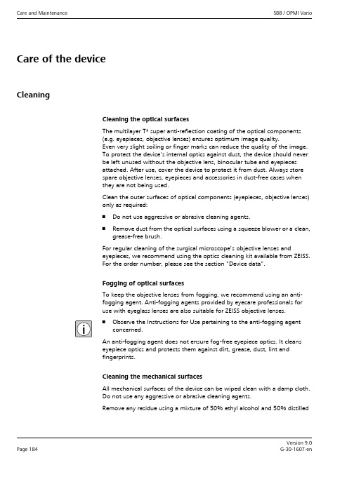
Care and Maintenance S88 / OPMI Vario Version 9.0Page 184G-30-1607-enCare of the deviceCleaningCleaning the optical surfacesThe multilayer T* super anti-reflection coating of the optical components(e.g. eyepieces, objective lenses) ensures optimum image quality.Even very slight soiling or finger marks can reduce the quality of the image.To protect the device's internal optics against dust, the device should neverbe left unused without the objective lens, binocular tube and eyepiecesattached. After use, cover the device to protect it from dust. Always storespare objective lenses, eyepieces and accessories in dust-free cases whenthey are not being used.Clean the outer surfaces of optical components (eyepieces, objective lenses)only as required:•Do not use aggressive or abrasive cleaning agents.•Remove dust from the optical surfaces using a squeeze blower or a clean,grease-free brush.For regular cleaning of the surgical microscope’s objective lenses andeyepieces, we recommend using the optics cleaning kit available from ZEISS.For the order number, please see the section "Device data".Fogging of optical surfacesTo keep the objective lenses from fogging, we recommend using an anti-fogging agent. Anti-fogging agents provided by eyecare professionals foruse with eyeglass lenses are also suitable for ZEISS objective lenses.•Observe the Instructions for Use pertaining to the anti-fogging agentconcerned.An anti-fogging agent does not ensure fog-free eyepiece optics. It cleanseyepiece optics and protects them against dirt, grease, dust, lint andfingerprints.Cleaning the mechanical surfacesAll mechanical surfaces of the device can be wiped clean with a damp cloth.Do not use any aggressive or abrasive cleaning agents.Remove any residue using a mixture of 50% ethyl alcohol and 50% distilledVersion 9.0G-30-1607-en Page 185S88 / OPMI Vario Care and Maintenancewater plus a dash of household dish-washing liquid.SterilizationAsepsis SetsThe Asepsis Sets supplied by ZEISS contain Asepsis Caps and resterilizablehandles which can be sterilized in an autoclave. For more detailed informationabout sterilization, please refer to the enclosed "Preparation of resterilizableproducts" manual for each Asepsis Set.Drapes (sterile covers)Disposable drapes can also be used to provide the device with a sterile cover.For a list of the types of drape recommended by ZEISS, see section "Systemdata – Ordering data".•Attach the sterile drapes loosely so that there is sufficient space for the movement of the surgical microscope and its suspension system.•To ensure that the lamps are able to cool sufficiently and to avoid any loss in lamp functionality, do not cover the ventilation slots.•Fasten the drape loosely using the adhesive strips.DisinfectionThe maximum concentrations for application are:–For alcohol (tested with 2-propanol): 60%–For aldehyde (tested with glutaraldehyde): 2%–For quaternary compounds (tested with DDAC): 0.2%NOTE This can damage the paintwork on the device!•Use an alcohol or aldehyde-based disinfectant. The use of quaternarycompounds as an additive is acceptable.To avoid damaging the surfaces, do not use any disinfecting componentsother than those specified below.。
797中文操作手册_ver5[1].0_
![797中文操作手册_ver5[1].0_](https://img.taocdn.com/s3/m/ff5d72a1b0717fd5360cdca1.png)
N I T O N 重金属元素分析仪X L t 797简易操作手册(塑料&合金模式)罗肯仕科技股份有限公司e R o H S T e c h n o l o g y C o .,L t d1. 开机: 按开关键约5秒,当按开关键或屏幕进入两侧灯亮,就放开4. 版权画面,按Yes进入安全保护密码画面,按屏幕输入密码1234,再按E 进入6. 主功能画面二、自动校正注意:工具及校正画面,按此进入校1. 按此进入工具及校正画面 2.正画面3. 自动校正画面,按此开始自自动校正中动校正6. 主功能画面5. 自动校正完成,按右键回主功能画面至此完成开机自动校正,可开始测试按”Bulk Sample Mode”进入1. 按”Mode”进入测试模式 2.塑料模式(ppm)按”Start”进行分析作业。
3. 按此进入测试分析模式 4.5. 分析仪检测时画面6. 按”Stop”即停止检测;完成检测程序完成后按”Return”或右键回到主功能画面8. 如需输入测试样品各项数据时,按Date Entry进入字段编码画面如有识别条形码,可按1依序(1-5)进行条形码扫瞄。
如无条形码,则按2依序键盘画面进入画面输入编号10. 按触控屏幕或计算机键盘输入编号。
数据编号完成,按Return回数据输入画面11. 按此” Batch”设定检测次数及秒数画面1212. 输入样品需检测次数(连续及时间(Sec),按ok键即可四、A l l o y合金模式测1. 按”Mode”进入测试模式选择2. 按“Alloy”进入合金模式(%)画面3. 按此进入合金判定及成份分析模式按”All Alloys”进入全合金自动测试画面5. 按”Start”进行分析作业(如需输入编号等数据,方式同PVC模式里步骤)6. 全合金自动测试检测时画面7. 测试完成后自动停止检测 8.按”Return”或右键回到主功能画面五、仪器示意图电池式意图开启NITON NDT 软件选取下载钮选取Query Reading 钮存放路径勾选资料选取要下载的数据,选择存放路径及设定文件名选取Download 钮下载数据选择 Done 钮完成下载工作NDT资料表Excel资料表八、检视测试资料I. 开启NITON NDT数据文件II. 点选 View Æ Customize Report 即出现以下对话框III. 勾选欲保留之字段或元素(本例为勾选 Index,Reading No,Time,Duration,Type,Unit,Cd,Pb,Br,Hg,Cr) ,并点选OK即可IV. 最后显示如以下画面III. 勾选Always load hidden readings 及Display ” < LOD ” 方块,Language则勾选Other。
USM35DAC操作指南_Common
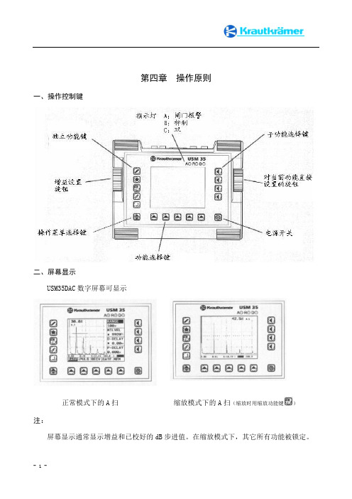
第四章操作原则一、操作控制键二、屏幕显示USM35DAC数字屏幕可显示正常模式下的A扫缩放模式下的A扫(缩放时用缩放功能键)注:屏幕显示通常显示增益和已校好的dB步进值。
在缩放模式下,其它所有功能被锁定。
功能显示在屏幕下部显示五组功能。
当前所选择的功能被加亮(高亮)。
如下图所示,在A扫的附近,显示相应功能的子功能选项。
在缩放模式下,这些功能不显示。
其它显示在屏幕下方显示的测量线表明设置值、测量值、状态指示。
作为一种替换,这里还可显示一个标尺以表明回波位置。
注:1、在A扫的右上角,每个测量值都被放大显示。
(在MEAS功能中用S-SIDP功能进行设置)2、用户可根据需要对设置值和测量值在测量线上对四个位置可配置(MSEL功能)。
请参考第五章第十四节的“配置测量线”部分。
三、按键和旋钮功能键操作菜单选择键:选择操作菜单功能选择键:选择功能子功能选择键:选择子功能电源开关接通或断开设备电源独立功能键仪器单独使用的功能:选择增益量冻结A扫图像显示缩放A扫传输数据记录测量值和保存数据旋钮USM35DAC配有两个旋钮。
左旋钮可直接设置增益;右旋钮用于对所选用功能进行设置。
两个旋钮既可一步一步地进行仪器设置,也可快速设置。
慢旋旋钮,用户可一步一步地设置。
要快速设置,可以连续转动旋钮。
这样就在两个设置之间快速地转换,而不考虑两者间的较大的差距。
四、操作术语USM35DAC超声波探伤仪,操作简单,使用方便。
该机有三种操作菜单,可使用选择三种操作菜单。
根据第一二个功能之间的数字,用户很容易获知当前的操作菜单。
如果仪器配有数据记录器,则还会有第四种操作菜单。
每种操作菜单中都包含五项功能。
如右图。
功能设置在A扫下面显示的是可直接使用相应的键选择的五个功能。
被选中的功能被高亮显示,其相应的四种子功能则显示在A扫的右边,这四种子功能可使用相应的键来选择。
具有双工作状态的功能一些功能具有双工作状态。
这些功能名称后面有一个箭头(>)。
USM图形规范手册说明书

1usm.clMANUAL DE NORMAS GRÁFICAS UNIVERSIDADTÉCNICA FEDERICO SANTA MARÍAACTUALIZACIÓN AÑO 202067usm.clMANUAL DE NORMAS GRÁFICASUNIVERSIDAD TÉCNICA FEDERICO SANTA MARÍACAPITULO I NORMAS DE CONSTRUCCIÓNDESCARGAR ARCHIVO ILLUSTRATOR8COLORESCORPORATIVOSPALETA PARA CUATRICROMÍA (Impresión offset)PALETA HEXADECIMAL (Versiones digitales)Pantone DS 224-2 C:100 M:30 Y:0 K:35#004B85Pantone DS 268-1 C C:100 M:0 Y:80 K:20#008452Pantone DS 87-1 C C:0 M:100 Y:90 K:10 #D60019Pantone DS 18-1 C C:0 M:35 Y:100 K:0#F7AE00Pantone DS Process Black C C:100 M:100 Y:100 K:100#000000Para su correcta aplicación, todo uso de la marca institucional debe ser visada por la Dirección General de Comunicaciones.9usm.clVERSIONES EN BLANCO Y NEGRODe existir restricciones cromáticas en las piezas gráficas donde se deba ocupar, se presentan dos alternativas junto a su paleta para utilizar nuestra marca.Pantone DS Process Black C C:100 M:100 Y:100 K:100:C: 0 M: 0 Y: 0 K: 70MANUAL DE NORMAS GRÁFICASUNIVERSIDAD TÉCNICA FEDERICO SANTA MARÍACAPÍTULO I NORMAS DE CONSTRUCCIÓN10VERSIONES SOBRE FONDOSEn caso que nuestra marca se deba presentar sobre fondososcuros, hay dos formas para agregarla.Como primera alternativa con el escudo en sus colores cor-porativos regulares.Para su correcta aplicación, todo uso de la marca institucional debe ser visada por la Dirección General de Comunicaciones.11usm.clComo segunda opción en color blanco en el caso que debacontrastar con esa paleta.MANUAL DE NORMAS GRÁFICASUNIVERSIDAD TÉCNICA FEDERICO SANTA MARÍACAPÍTULO I NORMAS DE CONSTRUCCIÓN12TIPOGRAFÍALa familia tipográfica corporativa es la Times New Roman, en sus versiones normal, cursiva y negrita cursiva.Para el logotipo se usaron solo las mayúsculas o altas.13usm.clTimes New RomanRegularTimes New RomanBoldTimes New RomanItalicTimes New RomanBold ItalicRoboto CondensedQWERTYUIOPASDFGÇHJKLÑZXCVBNM qwertyuiopasdfgçhjklñzxcvbnm 1234567890!”·$%&/()=?¿`+´ç,.-^*¨QWERTYUIOP ASDFGÇHJKLÑZXCVBNM qwertyuiopasdfgçhjklñzxcvbnm 1234567890!”·$%&/()=?¿`+´ç,.-^*¨QWERTYUIOPASDFGÇHJKLÑZXCVBNM qwertyuiopasdfgçhjklñzxcvbnm 1234567890!”·$%&/()=?¿`+´ç,.-^*¨QWERTYUIOPASDFGÇHJKLÑZXCVBNM qwertyuiopasdfgçhjklñzxcvbnm 1234567890!”·$%&/()=?¿`+´ç,.-^*¨QWERTYUIOPASDFGÇHJKLÑZXCVBNM qwertyuiopasdfgçhjklñzxcvbnm 1234567890!”·$%&/()=?¿`+´ç,.-^*¨MANUAL DE NORMAS GRÁFICASUNIVERSIDAD TÉCNICA FEDERICO SANTA MARÍACAPÍTULO I NORMAS DE CONSTRUCCIÓN14ÁREA DE RESERVAEl área de reserva es el espacio de protección que no debe ser ocupado por ningún elemento gráfico, lo que nos asegura mayor legibilidad.El área de reserva de nuestra marca vertical corresponde a la se-paración que generan dos aspas del escudo izquierdo, ubicados desde la esquina superior izquierda y la esquina inferior dere-cha.TAMAÑO MÍNIMO PERMITIDOSe ha estipulado un tamaño mínimo permitido para laconstrucción y aplicación de la marca vertical, asegurandouna óptima legibilidad.1,5 cmMANUAL DE NORMAS GRÁFICAS UNIVERSIDAD TÉCNICA FEDERICO SANTA MARÍA CAPÍTULO I NORMAS DE CONSTRUCCIÓNPara dudas y consultas sobre el correcto uso de la marca institucional, escribir a:************122。
EF200mmf2L镜头中文说明书

预设距离的对焦方法
向左或向右转动播放环 , 完全按下快门按钮。
¡ 镜头将对焦在预设距离。 ¡ 如果对焦预设开关设置为 , 蜂鸣器会鸣响两次。
设置方法
设置对焦预设开关或 。 半按快门按钮,对焦想要预设的距离。 按对焦预设按钮。
部件名称 电气实装部分 金属部件
铅 (Pb) × ×
汞 (Hg) ○ ○
有毒有害物质或元素 镉 六价铬 多溴联苯 多溴二苯醚 (Cd) (Cr(VI)) (PBB) (PBDE) ○ ○ ○ ○ ○ ○ ○ ○
○:表示该有毒有害物质在该部件所有均质材料中的含量均在 SJ/T11363-2006标准规定的限量要求以下。 ×:表示该有毒有害物质至少在该部件的某一均质材料中的含量超出 SJ/T11363-2006标准规定的限量要求。 FOR P.R.C. ONLY 本标志适用于在中华人民共和国销售的电子信息产品、标志中央的数字 代表产品的环保使用期限。
CHI-3
1. 安装和卸下镜头
有关安装和卸下镜头的详细说明, 请参阅相机的 使用手册。
镜头安装部位具有加强防水和防尘性能的橡皮 环。 该橡皮环可能导致相机的镜头安装部位出现 轻微的磨损,但这不会带来任何问题。如果橡皮 环老化或损坏,可以在佳能服务中心自费更换。
¡ 卸下镜头后,将镜头后端朝上放置,以避免划 伤镜头表面和电子触点。 ¡ 如果电子触点被弄脏,划伤或沾有指纹,可能 会导致腐蚀或接触不良。 相机和镜头就可能无 法正常工作。 ¡ 如果电子触点被弄脏或沾上指纹, 请用柔软的 布将其擦净。 ¡ 取下镜头时,需要装上防尘盖。要正确安装防 尘盖, 将如图所示的防尘盖上的○标记对准镜 头安装标记,并朝顺时针方向转动。要取下防 尘盖,则朝逆时针方向转动。
OMC日常维护

BCCH/BSIC on cell ... “,操作无法继续: 原因:OMCR检查要求小区的所有临小区必须有不同的BCCH/BSIC,一般在大量改频后可 能会出现; 解决方法:创建新的PRC,把相关的小区的切换关系删除,如果需要,再添加上。
2.
小区的 Alignment Status一直是“inConfig”: Status inConfig”
4.
BSS discovery或BSS/cell upload时给出提示消息:WARNING BSSIM-5529 "FOR
THE CELL (LAC XXX,CI YYY),THERE IS A RESELECTION”; 解决方法:及时检查OMCR上数据库的不一直并消除; 5. PRC激活时给出消息:“ERROR - RNIM-1005 : STUBBED ACTIVATION MODE: PRC ACTIVATION WILL NOT BE DOWNLOADED TO ANY NE”; 原因:逻辑参数修改已经更新了OMC上相关数据库,但没有更新到BSC,一般发生在 OMCR升版后没有做clean up; 解决方法:在OMC上做 clean up axadmin@host$/alcatel/omc3/migration/script/cleanUp.pl axadmin@host$/alcatel/omc3/migration/script/cleanUpPRC.pl
BSSIM-5513 : FOR THE CELL(LAC XXX, CI YYY),THERE IS A RESELECTION FOUND ON BSCBUT NOT CREATED ON OMC, WITH BCCH FREQUENCY BBB
Alcatel OMCR training reference doc
佳能 EF24mm f 1.4L II USM镜头 说明书

摄距离和放大倍率显示如下。
放大倍率为 0.05 ×- 0.21 ×。
EF12 ll
相机至拍摄主体 的距离(mm)
近
远
156
167
放大倍率
近
0.67x
远
0.50x
¡不能安装近摄镜头 250D,因为没有适合的尺寸。 ¡ 若要精确对焦,建议采用手动对焦。
¡EF25 II 增距延长管不能用于此镜头。 ¡若要精确对焦,建议采用手动对焦。
使用本镜头前,请详细阅读使用手册,使您对镜头 更熟悉并掌握正确的操作方法。 如果遇到不能解决的问题 , 请联系随机附送顾客联 络表上列印的服务中心。
¡“USM”表示超声波马达。
特点
1. 非球面镜片和 UD 超低色散镜片能使影像清晰, 轮廓鲜明。
2. SWC(亚波长结构表层)大大地降低了以锐角进入 的光所引起的鬼影和眩光。
CHI-1
a 安全注意事项
a 安全注意事项
¡ 请勿透过镜头或相机观看太阳或明亮的光源。 否则会使视力受损。透过镜头直接观看太阳尤 其有害。
¡ 无论镜头是否装在相机上,请勿将没有盖上镜 头盖的镜头置于太阳下。否则镜头可能汇聚光 线并引起火灾。
使用注意事项
¡ 如果将镜头从寒冷的环境拿到温暖的环境中, 镜头表面和内部零件可能会发生结露。为了防 止在这种情况下出现结露,将镜头从寒冷的环 境拿到温暖的环境之前,先将镜头放入密封的 塑料袋里。镜头逐渐变暖以后,再将其拿出来 使用。将镜头从温暖的环境拿到寒冷的环境中 时,也请使用同样的方法。
用于补偿由于温度变化而导致无限远对焦点的偏移。 L 标记垂直线和距离刻度上的距离指示标记对齐的 一点就是常温下的无限远位置。
要精确地对无限远主体进行手动对焦,请在转动对 焦环时通过取景器观看或者观看液晶屏幕上的放大 图像 *。
佳能镜头 EF24-105mm F4L IS USM 使用手册 PDF

CHI-8
7. 遮光罩
遮光罩 EW-83H 能够阻挡不必要的光线进入镜头,并能保护镜头,使其避免受到雨、雪和灰尘的侵扰。
安装遮光罩时, 将遮光罩的安装位置标记对准镜头前部的红色圆点, 然后按箭头所示的方向转动遮光罩, 直至镜头的红色圆点与遮光罩停止位置标记排成一线。 可以将遮光罩反面安装在镜头上以便存放。
此镜头的图像稳定器可以有效用于下 列情况下的手持拍摄方式。 ¡在较暗的环境中,例如室内或夜晚 时的室外。 ¡在禁止使用闪光灯拍摄的地方,例 如艺术博物馆和剧院舞台。 ¡在您站立不稳的情况下。 ¡在无法使用快速快门设置的情况 下。
OP C
CHI-6
图像稳定器 ¡图像稳定器不能补偿由于主体移动而导致的 画面模糊。 ¡当使用 B 门设定(长时间曝光)拍摄时,请 将 STABILIZER(稳定器)开关推到 (关) 如果这时该开关是在 。 (开) 位置, 图像稳定器功能可能会出错。 ¡图像稳定器可能在下列情况下不能完全起 作用: ¡ 摇摄时移动照相机。 ¡ 在颠簸的道路上乘车拍摄。 ¡使用图像稳定器要比一般的拍摄方式消耗更 多的电量,因此如果您使用此功能,拍摄次 数会减少。 ¡即使手指松开快门键, 图像稳定器还会运行 约 2 秒钟。不要在稳定器正在工作时取下镜 头,否则会造成故障。 ¡当使用EOS-1V/HS、 30/33、30V/33V、 3、 50/50E、300、IX 和 D30 拍摄时,在自拍 定时器工作的过程中,图像稳定器不起作 用。 ¡使用三脚架拍摄时,应关闭图像稳定器以 节省电池电量。 ¡手持相机拍摄和用独脚架拍摄时,图像稳 定器具有同等效果。 ¡镜头使用 EF12 ll 或 EF25 ll 增距延长管 时,图像稳定器功能仍然有效。 ¡有些相机取景后图像可能显示变形,但这 并不影响拍摄。 ¡如果设置相机的自定义功能(Custom Function)改变了指定操作 AF(自动对 焦)的按钮,则按下最近指定的 AF 按钮, 可以启动图像稳定器。
常用维护手册使用指南APS-320-ME-00-01
常用维护手册使用简介编制单位:沈阳维修基地适用区域:☑工程部机关☑各维修单位☑其他:发布范围:各维修单位航线维护部门执行负责人:流程负责人:文件批准人:生效日期:年月日目录1.A-生产有准备 (3)1.1 技术文件 (3)1.2 工具设备 (3)1.3 航材物资 (4)1.4 技术人员 (4)1.5 工作环境 (4)2. P-施工程序 (5)2.1 手册编写标准 (5)2.1.1 ATA100 (5)2.1.2 ATA2200 (6)2.1.3 ASD-STE100 (6)2.2 手册有效性 (6)2.2.1 客户化手册 (6)2.2.2 有效性对照表 (7)2.3 ADOC N@vigator (7)2.3.1 介绍 (7)2.3.2 ADOC N@vigator安装和登陆 (8)2.3.3 ADOC N@vigator使用 (12)2.4 AMM手册使用 (16)2.4.1 AMM手册主要内容 (16)2.4.2 FIN号 (16)2.4.3 AMM手册查找方法 (17)2.5 IPC手册使用 (19)2.5.1 IPC手册主要内容 (19)2.5.2 详解零件清单 (19)2.5.3 互换性信息 (22)2.5.4 IPC查找方法 (24)2.6 TSM手册使用 (25)2.6.1 TSM手册主要内容 (25)2.6.2 TSM/Troubleshooting使用 (25)3 S-工作有标准 (30)1.A-生产有准备1.1 技术文件1.2 工具设备1.3 航材物资1.4 技术人员1.5 工作环境2. P-施工程序2.1 手册编写标准2.1.1 ATA100ATA100规范是美国航空运输协会(Air Transport Association of America)第100号规范,又称“制造商技术资料规范”。
它详细规定了飞机制造商技术资料的标准和指导原则,包括手册的结构、内容、编排、版本及更新服务,确保了民用航空器各种产品在设计、制造、使用、维修中各种资料、文件、函电、报告、目录索引中编号的统一。
EF28-135mm镜头中文说明书

自动对焦) )下进入对焦范围,可以进行手动对焦。
使用注意事项
如果将镜头从寒冷的环境拿到温暖的环境中,镜头表面和内部 零件可能会发生结露。为了防止在这种情况下出现结露,将镜 头从寒冷的环境拿到温暖的环境之前,先将镜头放入密封的塑 料袋里。镜头逐渐变暖以后,再将其拿出来使用。将镜头从温 暖的环境拿到寒冷的环境中时,也请使用同样的方法。
Cs EF12 Ⅱ或 EF25 Ⅱ增距延长管进行放大拍摄。拍摄距离和放大倍率显示如下。 焦距范围(毫米) 近 远 近 放大倍率(×) 远
EF12 II EF25 II
28mm 135mm 28mm 135mm
180 336 169 280
196 1624 174 876
Cs -4
2. 变焦
转动镜头的变焦环以进行变焦。
请确保在进行对焦之前完成变焦工作。在对焦完成后变动 变焦环会影响对焦。
3. 设置对焦模式
要在自动对焦(AF)模式下进行拍摄,请将对焦模式开关设置为 AF。在手 动对焦(MF)模式下进行拍摄,请将对焦模式开关设置为 MF,然后转动对 焦环进行对焦。您可以在所有对焦模式下使用对焦环。
在单次自动对焦(ONE SHOT AF)模式下进行自动对焦后,您可以半按快门键 并转动对焦环来进行手动对焦(全时手动对焦) 。
USM锐化滤镜

USM锐化滤镜Ps菜单:滤镜/锐化/USM 锐化Filter/Sharpen/USM Sharpen采用照相制版中的虚光蒙版(模糊遮罩,USM,Unsharpen Mask)原理,通过加大图像中相邻像素间的颜色反差,使图像的不同颜色之间生成明显的分界线,一条亮线和一条暗线,从而使边缘突出,达到锐化图像的目的。
USM 锐化 USM Sharpen滤镜是所有锐化类滤镜中锐化效果最强、速度最快的滤镜。
◆◆◆USM 锐化滤镜选项说明▪数量Amount锐化的强度。
将颜色交线处的暗色变暗、亮色变亮的幅度大小。
其值越大,锐化程度越强。
取值范围在 1% ~ 500%,通常范围在 50% ~ 250%,最常用范围在 50% ~ 150% 。
在判定数量大小之前,应将图像 100% 显示。
▪半径Radius确定在多大范围内搜索像素间的差异,即 USM 锐化的运算范围,或者说是暗色与亮色发生变化的范围,即光晕的宽度。
较低的数值仅锐化边缘像素,较高的数值则锐化范围更宽的像素。
以发生变化的颜色跟交线的位置确定,单位为像素。
取值范围在0.1 ~ 1000.0个像素。
通常使用 2 个以下的像素,尤其是对于高分辨率图像。
如果半径值为1,则从亮到暗的整个宽度是两个像素。
如果半径值为2,则边缘两边各有两个像素点,那么从亮到暗的整个宽度是4 个像素。
半径越大,细节的差别也清晰,但同时会产生光晕。
选择合适半径的关键是:能否接受应用该半径后所丢失的细节。
如果将半径值设为较大,比如 20,数量值设为较小,比如 50%,就相当于 ACR 中的清晰度滑块的作用。
▪阈值Threshold用于降低锐化后的噪点。
决定多大反差的相邻像素边界可以被锐化处理,而低于此反差值就不作锐化。
阀值的设置是避免因锐化处理而导致的斑点和麻点等问题的关键参数。
正确设置后就可以使图像既保持平滑的自然色调(例如背景中纯蓝色的天空)的完美,又可以对变化细节的反差作出强调。
取值范围在0 ~ 255,推荐值为3 或 4。
EF70-300mmf4.5-5.6 DO IS USM镜头中文说明书

部件名称 电气实装部分 (Hg) ○ ○
有毒有害物质或元素 镉 六价铬 多溴联苯 多溴二苯醚 (Cd) (Cr(VI)) (PBB) (PBDE) ○ ○ ○ ○ ○ ○ ○ ○
a 拍摄的注意事项
如果在暗处使用该镜头拍摄 十分明亮的聚焦光线时, 例 如水银灯等, 光源的四周可 能会产生光环, 这是使用多 层衍射光学元件的缘故。
CHI-4
3. 变焦
4. 遮光罩
转动镜头的变焦环以进行变焦。
请确保在进行对焦之前完成变焦工作。 在对焦完 成后变动变焦环会影响对焦。
遮光罩 ET-65B 能够阻挡不必要的光线进入镜 头,并能保护镜头,使其避免受到雨、雪和灰尘 的侵扰。 将遮光罩安装和调整至镜头前面的遮光罩座上, 按箭头所示方向旋转遮光罩以将其固定。 可以将遮光罩反面安装在镜头上以便存放。
¡ “DO”表示衍射光学元件。 ¡ “IS”表示图像稳定器。 ¡ “USM”表示超声波马达。
特点 1. DO元件可用于调整因使用望远变焦镜头而出 现的颜色失真, 有助于实现更小型化以及卓越 的图像品质。 2. 图像稳定器能够达到提高三档快门速度的效 果 *。 3. 可以将变焦环锁定,使镜头固定在最近位置。 4. 装配超声波马达 (USM) 实现了高速和静音自 动对焦。 5. 当拍摄对象在自动对焦模式 ONE SHOT AF ( (单次自动对焦) 下进入对焦范围, ) 可以进行 手动对焦。 6. 真正的圆形光圈生成更好的背景模糊效果。
2. 设置对焦模式
¡ 卸下镜头后,将镜头后端朝上放置,以避免划 伤镜头表面和电子触点。 ¡ 如果电子触点被弄脏,划伤或沾有指纹,可能 会导致腐蚀或接触不良。 相机和镜头就可能无 法正常工作。 ¡ 如果电子触点被弄脏或沾上指纹, 请用柔软的 布将其擦净。 ¡ 取下镜头时,需要装上防尘盖。要正确安装防 尘盖, 将如图所示的防尘盖上的○标记对准镜 头安装标记,并朝顺时针方向转动。要取下防 尘盖,则朝逆时针方向转动。
EF镜头使用说明书

本说明中使用的符号
避免对镜头或相机造成故障或 损坏的警告。 有关使用镜头和拍摄照片的补 充说明。
安全注意事项
做好预防措施可确保相机安全使用。 请仔细阅读这些预防措施。请确保遵 守一切细节,避免对用户和他人造成 危险和伤害。
警告
有关可导致死亡或严重伤害 的危险的详细说明。Байду номын сангаас
若要进行变焦,请转动镜头的变焦 环。
●●务必在进行对焦之前完成变焦工 作。在对焦完成后变动变焦环会 影响对焦。
●●如果快速转动变焦环,则会产生 暂时性的模糊现象。
●●相机关闭时变焦可能会导致对焦 延迟。
●●执行静态图像曝光时变焦可能会 导致对焦延迟。这会导致进行曝 光时所捕捉到的光线产生模糊。
CHI-1
滤光镜安装螺纹
对焦环
对焦模式开关 图像稳定器开关
变焦环锁定杆 电子触点 镜头安装标记
感谢您购买佳能产品!
佳能 EF70-300mm f/4-5.6 IS II USM 是适用于 EOS 相机的长焦变焦镜头。
●●"IS"表示图像稳定器。 ●●"USM"表示超声波马达。
相机固件
●●当使用该镜头时,请参照佳能网页, 获取最新相机固件信息。如果相机 固件不是最新版本,请确保升级至 最新固件。
●●请勿透过镜头或单镜头反光相机观 看太阳或明亮的光源。否则会使视 力受损。透过镜头直接观看太阳尤 其有害。
●●请勿将镜头或相机朝向太阳或进行 拍摄。由于镜头会聚集光线,因此 即使太阳不在图像区内或以背光拍 摄,也会导致相机故障或起火。
●●无论镜头是否装在相机上,请勿将 没有盖上镜头盖的镜头置于太阳 下。否则镜头可能汇聚光线并引起 火灾。
Canon佳能百微镜头EF100F28macrou中文使用说明书

CHI-8
使用三脚架座(选购件)
装上和卸下三脚架环 按下列程序装上三脚架环,按与此相反的程序卸下三脚架环。
将三脚架环转接器的标记 与镜头安装标记对齐,将转 接器推入镜头背后。 ¡ 三脚架环转接器里面的接头
应滑入镜筒上的槽内,这时 转接器应不能绕着镜筒转动。
1:5 3.6 +
1:3 4.1 +1
1 : 2 1 : 1.5 1 : 1 4.6 5.0 5.9 +1 +1 +2
(级)*
+
+1
+1
& 上面的数值∶1/3 级。下面的数值∶1/2 级。
照相机所显示的光圈是假定焦距为无限远时的数 值,以较此更近的对焦距离(放大率增加)拍摄 时,实际光圈(有效 f -值)变暗(有效 f -值增 加)。在普通拍摄时,这不会造成曝光问题,但在 近距离拍摄时,则不能忽视有效 f -值的变化。
滤光镜安装螺纹 (→ 10)
电子触点(→ 4)
镜头安装标记(→ 4)
对焦环(→ 4)
三脚架环转接器槽 (→ 8)
对焦距离范围选择开关 (→ 5) 请您参阅括号(→ **)中提供的参考页码,以了解更详细的信息。
CHI-3
1. 安装和卸下镜头
2. 设置对焦模式
有关安装和卸下镜头的详细说明,请参阅相机的 使用手册。
要精确地对无限远主体进行手动对焦,请在转动 对焦环时通过取景器观看。
¡ 当切换至垂直拍摄时,转动照相机,使把手朝 上。按相反方向转动照相机可将把手转进三脚 架环。
¡ 在装上或卸下镜头之前,将三脚架环设回到其 正常位置(水平拍摄位置)。否则,三脚架环 可能会撞入照相机把手或五棱镜中,妨碍镜头 装上照相机或从照相机上卸下。
超声波USM 86 详细操作手册

USM 86 操作手册
[Pick the date]
过摇杆进行控制,摇杆往左拔,光标将往左移动,摇杆往右拔,光标将往右移动, 摇杆往上拔,光标将往上移动,光标往下拔,光标将往下移动,光标在主菜单栏 可循环移动,在主菜单界面与设置菜单界面都是通过摇杆选择菜单。 2.2.2 改变参数
当光标在参数菜单栏时,通过摇杆可对光标选中的参数进行调整,如果所选 参数值为具体数字,通过摇杆可对具体数字进行微调,摇杆往左拔数字减小,摇 杆往右拔数字增大,摇杆左右拔的角度越大,数字变化越快,摇杆左右拔的角度 越小,数字变化越慢。 如果所选参数值为可选项,通过摇杆往左往右拔可使参 数值在可选值中切换 2.2.3 摇杆除控制光标移动,改变参数外,还具有如下功能。
2.4 快捷键
为方便用户操作方便,在功能菜单模式下,光标处于功能菜单中时,功能 1 和功能 2 键可作为快捷键使用,快捷键可在功能菜单中设置。
当仪器在主菜单显示界面下,光标在主菜单栏时,功能键 1 与功能键 2 可以 使用预先设置的快捷键功能,快捷键功能可以设置 4 个,功能键 1(短按),功 能键 1(长按) ,功能键 2(短按),功能键 2(长按),用户可以根据自已的使
2
USM 86 操作手册
[Pick the date]
第一部分 仪器外观及显示菜单
1.1 仪器外观
电池 支架
充电器接口 探头线接口 电源开关
外设接口保护盖,往左拔打开,右拔关闭
USB 接口
调试用串口接口
SD 卡
3
USM 86 操作手册
1.2 显示界面
当前增益步距
仪器开机后直接显示主菜单界面,如下图所示。
按下摇杆,操作模式下,短按摇杆,在标准界面和全屏界面之间切换。 按下摇杆,设置菜单下,短按摇杆,激活或者取消当前参数。 按下摇杆 2s,操作模式和设置菜单切换。 左右摇动摇杆,操作模式下,调节光标位置参数。设置菜单下,切换功能选 项。
USM33探伤仪使用说明

0~60℃
重量
177mmx230mmx76mm
1.8Kg(包括电池)
USM33 技术参数
检测范围
频率范围 声速范围 扫描延迟 探头延迟 自动校准
最小:0~0.5mm+10%(钢) 最大:0~9999mm+10%(钢) 0.5~20MHz 自由匹配 1000~15000m/s,1m/s 步进连续可调 -10~1000mm 0~200us 通过两个已知参考回波自动校准声速和探头延迟
单位
毫米或英寸
数据存储
200 条仪器设置参数,能够存储 A 扫描图像,并能够调用或输出到计算机
文件操作
通过英文或中文显示字幕,并通过文件存储 A 扫描图像,测量数据和参数设置
打印机接口
HP DJ 1200(DeskJet)、HP LJ1012(LaserJet)、EPSON FX/LX、SEIKO DPU
上海洪富仪器仪表有限公司 021-56615302
汽车行业的精准厚度测量 - 你可以根据每一个回波信号的波峰值精准地测量声程差,分辨率 0.01mm。在测量过程中,触发门自
动定位于第一次回波,保证测量数据的正确显示
电力和石化行业的腐蚀壁厚测量 - 采用双晶探头检测受腐蚀工件的壁厚,可以同时察看读数和 A 扫描显示,极大增强了检测可靠性。在高
- 应用遍及汽车、电力、石油天然气到航空航天领域
其他优点 - 我们还从电脑工业的电池概念中进行了创新,令您的日常工作更加轻松:充电式锂电池组让您可以将检
测持续至少 8 小时。充电可以在仪器内部轻松进行,您只需将电池充电器接上 USM 33 过夜即可 - 紧凑的结构设计,人性化的操作方式,适应接口跟计算机通讯
VGA 输出
可外接显示器
超声波金属探伤仪USM 36仪器操作规程
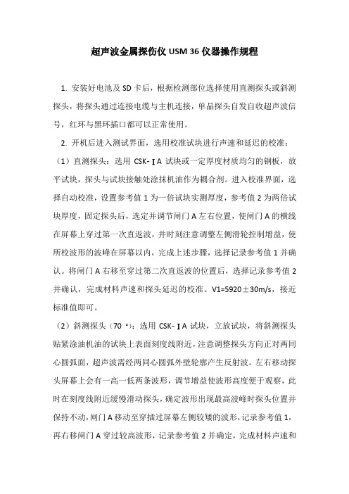
超声波金属探伤仪USM 36仪器操作规程1. 安装好电池及SD卡后,根据检测部位选择使用直测探头或斜测探头,将探头通过连接电缆与主机连接,单晶探头自发自收超声波信号,红环与黑环插口都可以正常使用。
2. 开机后进入测试界面,选用校准试块进行声速和延迟的校准:(1)直测探头:选用CSK-ⅠA试块或一定厚度材质均匀的钢板,放平试块,探头与试块接触处涂抹机油作为耦合剂。
进入校准界面,选择自动校准,设置参考值1为一倍试块实测厚度,参考值2为两倍试块厚度,固定探头后,选定并调节闸门A左右位置,使闸门A的横线在屏幕上穿过第一次直返波,并时刻注意调整左侧滑轮控制增益,使所校波形的波峰在屏幕以内,完成上述步骤,选择记录参考值1并确认。
将闸门A右移至穿过第二次直返波的位置后,选择记录参考值2并确认,完成材料声速和探头延迟的校准。
V1=5920±30m/s,接近标准值即可。
(2)斜测探头(70 °):选用CSK-ⅠA试块,立放试块,将斜测探头贴紧涂油机油的试块上表面刻度线附近,注意调整探头方向正对两同心圆弧面,超声波需经两同心圆弧外壁轮廓产生反射波。
左右移动探头屏幕上会有一高一低两条波形,调节增益使波形高度便于观察,此时在刻度线附近缓慢滑动探头,确定波形出现最高波峰时探头位置并保持不动,闸门A移动至穿插过屏幕左侧较矮的波形,记录参考值1,再右移闸门A穿过较高波形,记录参考值2并确定,完成材料声速和探头延迟的校准。
V2=3235±15m/s,校准数值接近标准值即可。
3. 斜测探头角度校准:进入校准界面选择角度校准,试块选用CSK ⅠA 60-75,探头在K2.5与K3.0刻度之间缓慢移动,使屏幕上一条最明显的波形出现最高波峰,移动闸门A穿过波形线,并记录所校准的角度值,接近70 °即可。
角度校准在仪器使用不频繁或斜探头上的耐磨层磨损不严重时可放宽至几个月校准一次即可。
4. DAC曲线的建立:主界面进入DAC曲线,选择记录,此处需用到校准试块CSK-ⅢA的上表面和下底面,依次选取3-5点进行测量并记录,预判第一个缺陷孔洞对应探头角度的位置,左右移动斜探头找到波峰最高位置,移动闸门A穿插过波形线后点自动80再点记录1点数,第二、三个缺陷孔洞进行相同操作后,即可得到创建DAC曲线的母线,在标准选择中可直接选用4730标准,也可以选择自定义后在曲线中根据不同规范要求设置判废线和评判线,以正负dB为单位显示。
- 1、下载文档前请自行甄别文档内容的完整性,平台不提供额外的编辑、内容补充、找答案等附加服务。
- 2、"仅部分预览"的文档,不可在线预览部分如存在完整性等问题,可反馈申请退款(可完整预览的文档不适用该条件!)。
- 3、如文档侵犯您的权益,请联系客服反馈,我们会尽快为您处理(人工客服工作时间:9:00-18:30)。
DANIEL
超声波流量计安装使用及维护
DANIEL 超声波流量计主要由如下部分组成:
MARK II变送器:
超声波探头:
超声波本体:
MARK II 变送器电子部件组成如下:
MARK II 变送器主要电子部件有三块板:
DFI板,电源板和CPU板
超声波探头T-SLOT TRANSDUCER的组成如图所示:
探头电缆可以在线更换
流量计的安装
在DANIEL 超声波流量计到达现场时,MARK II 与本体是分开包装的。
首先应将它们组装到一起。
具体步骤如下:
1.在连接MARK II 与本体的O型圈上涂抹润滑油。
2.将MARK II 靠近仪表本体,连接从MARK II到本体上的前置放大器之间的连线。
3.小心的将MARK II 就位,注意电缆不要缠绕,拧紧四个用于固定的
内六角螺丝。
4.将前置放大器到各个探头之间的连线连接好。
注意电缆上的号码与探头上的号码要一一对应。
流量计的安装可参考下图:
流量计的接线
DANIEL 超声波流量计的接线板位于MARK II 的一侧,旋开MARK II 两侧的盖子就可以看到。
如图所示:
具体的接线方式可以参考下图:
在MARK II 通讯接线板上可以看到接线柱旁写有如下标识:
GND,485+,485-.此为通讯口一,是RS485通讯口。
GND,RXD,TXD.此为通讯口二,是RS232通讯口。
注意:可以有一个可选的RS485通讯口。
当选择RS485通讯方式的时候,注意要将MARK II 上的
RS485/RS232开关打到正确位置。
同时通讯板上的JUMPER 从1-6必须置于“ON”的
位置。
如果要将RS485通讯口该为RS232接口,可以将通讯
板(通讯接线板的另一侧)上的JUMPERJ4-J6处于”OFF”状
态(断开)。
输出接线可以参考下图:
注意:流量计有两个频率输出。
投运之前应注意的情况:
I.超声波流量计的的安装:
安装应注意流量计的上游至少保留10D的距离,下游为5D的距离。
上下游直管段内径与超声波流量计的内径之差小于超声波流量计内径的1%,其绝对值应小于5mm.
2.温变的安装应该在流量计的下游3-5D范围内,传感器插入深度大于75mm,测温点在管道的中心附近。
压力变送器在超声波流量计本体取压。
在流量计本体上有取压口。
当压变为绝压变送器,注意在流量计算机中输入大气压力为0, 当压变为表压变送器,注意在流量计算机中输入当地大气压。
流量计的日常维护
在日常工作中,在DUI软件中要注意下面的参数:
1.每个声道的增益(AGC)
根据下列步骤可以参看增益:
Flow data/Flow data sourceslect/predefine/Gain Selection/
按Control panel 上的”run”键。
几十秒后出现如下内容:
Gain setting upstrm:各声道信号上行的增益, Gain setting dnstrm:各声
道信号下行的增益。
增益的最大值为180,当测的值大于170即视为不正常。
一般160以下为正常值。
如果增益大于160,要检查是否是由
管道压力过低、或者传感器脏污造成的。
2.信号质量与噪音
根据根据下列步骤可以参看信号质量与噪声。
Flow data/predefine/signal quality/
按Control panel 上的”run”键。
几十秒后出现如下内容:
signal Max upstrm:表示各声道上行的质量, signal Max dnstrm:表示各声道下行的质量,该数字越大,表示信号质量越高。
正常的信号质量应该在五位以上。
Noise Max upstrm:表示各声道上行传输的噪声, Noise Max dnstrm:表示各声道下行传输的噪声。
该数值越小,表示噪声越小,也表示流量计工作正常,当该数值大于100之后,说明工作不正常,应该检查管道配置。
消除噪声。
3.察看流量,声速,平均流速,工况流速。
Flow data/predefined/Flow data/
按Control panel 上的”run”键。
几十秒后出现如下内容:
Flow velocity 为各声道当时的流速。
Sound Velocity为当时的声道声速。
AVG Flow velocity 为各声道当时的平均流速。
AVG Sound Velocity为当时的声道平均声速。
附录:单个超声波流量计与S500流量计算机相连接。
接线:
A端 B端
回到电源负端
注意:RS485通讯时,首先注意要把485通讯板上的1~6跳线置到ON 的状态.其次注意要把超声波流量计的1~6跳线置于ON的装态.
10
11
04/13/13
D:\iknow\docshare\data\cur_work\136945567.doc。