天锻液压机1000U说明书
天锻液压机培训教材 - 副本

1.按电气原理图和说 明检查并修理。 2.加油至油标位置。 3.清洗滤油器。 4.修理或更换。
滑块运动时 有抖动现象
1.系统内积存空气或 泵吸油口进气。 2.精度调整不当或导
1.检查吸油管路是否 松动,并打开放气阀 排气。 2.导轨上加注油,重
故障和消除方法 故障现象 一般原因 消除方法
滑块慢速下 行带压过高
•
1.3滑块及液压垫 精度的调整
• 1.3.1滑块导轨的结
构采用四角八面导 轨,具有可调节性, 可以精确调节滑块 的与工作台平面的 平行度与垂直度。 红色、蓝色分别为 大导轨、小导轨, 黄色为导板,紫色 为调整部分
•
• 1.3.2液压垫导轨采用每面双导轨调节。 • 调节部位位于下梁内部的安装孔内。
支承压力过大
调整压力阀,使上缸 不带压
停车后滑块下 溜严重
1.回程腔密封圈渗漏。 1.更换密封圈 2.支撑阀调整压力过 2.调整压力检查阀口 小或阀口不严。
故障和消除方法 故障现象 一般原因
1.压力表油路内存有 空气。 2.管路机械振动。 3.压力表损坏。
消除方法
压力表指针摆 动厉害
1.上压时略拧松管接 头放气。 2.将管路卡牢。 3.更换。
进行测量,发现 某一角低了,应 该松低角的导轨, 紧对面角的导轨。
1.4滑块、液压垫吨位与模具大小关系
• 1.4.1滑块上压的吨位,必须于设备模具面积成正
• •
比例关系。 严禁超出规范的使用大吨位压制小面积的模具。 1.4.2液压垫的吨位,必须配置对应数量的顶杆, 顶杆的分布必须要均匀。 对于直径48mm的顶杆,承压能力为12吨,挤压 应力按照700千克/平方厘米。 详见说明书中表格。
逐渐增多,目前液压系统越来越多的开始采用插 装阀系统,逐渐取代了电磁阀的控制系统。在本 台设备的液压主系统中,电磁换向阀只起到了控 制先导油的作用。
四柱液压机说明书

四柱液压机说明书1、主液压泵(恒功率输出液压泵),2、齿轮泵,3、电机,4、滤油器,5、7、8、22、25、溢流阀,6、18、24、电磁换向阀,9、21、电液压换向阀,10、压力继电器,11、单向阀,12、电接触压力表,13、19、液控单向阀,14、液动换向阀,15、顺序阀,16上液压缸,17、顺序阀,20、下液压缸,23节流器,26、行程开关四柱万能液压机的启动:电磁铁全断电,主泵卸荷。
主泵(恒功率输出)→电液换向阀9的M型中位→电液换向阀21的K型中位→T四柱万能液压机的启动:电磁铁全断电,主泵卸荷。
主泵(恒功率输出)→电液换向阀9的M型中位→电液换向阀21的K型中位→T液压缸16活塞快速下行:2YA、5YA通电,电液换向阀9右位工作,道通控制油路经电磁换向阀18,打开液控单向阀19,接通液压缸16下腔与液控单向阀19的通道。
进油路:主泵(恒功率输出)→电液换向阀9→单向阀11→液压缸16上腔回油路:液压缸16下腔→电液换向阀9→电液换向阀21的K型中位→T液压缸活塞依靠重力快速下行:大气压油→吸入阀13→液压缸16上腔的负压空腔液压缸16活塞接触工件,开始慢速下行(增压下行):液压缸活塞碰行程开关2XK使5YA断电,切断液压缸16下腔经液控单向阀19快速回油通路,上腔压力升高,同时切断(大气压油→吸入阀13→上液压缸16上腔)吸油路。
进油路:主泵(恒功率输出)→电液换向阀9→单向阀11→液压缸16上腔回油路:液压缸16下腔→顺序阀17→电液换向阀9→电液换向阀21的K型中位→T四柱液压机的启动保压:液压缸16上腔压力升高达到预调压力,电接触压力表12发出信息,2YA断电,液压缸16进口油路切断,(单向阀11和吸入阀13的高密封性能确保液压缸16活塞对工件保压,利用液压缸16上腔压力很高,推动液动换向阀14下移,打开外控顺序阀15,防止控制油路使吸入阀1误动而造成液压缸16上腔卸荷)当液压缸16上腔压力降低到低于电接触压力表12调定压力,电接触压力表12又会使2YA通电,动力系统又会再次向液压缸16上腔供应压力油……。
天锻锻压设备200T热压液压机技术方案

天锻锻压设备200T热压液压机技术方案技术协议甲方:乙方:甲乙双方经过友好协商,就甲方委托乙方设计制造200吨框式加热液压机事宜达成一致,特签订本协议,对设备的具体技术要求确定如下:一、机器型号、名称和数量1、Y96-200 2000KN 框式加热液压机1台二、机器的主要用途和工作条件:2.1本机是为用户设计、制造的碳纤维制品成型的框式液压机。
主要用于碳纤维制品的成型工艺。
2.2机器允许工作环境温度:0~45℃:供水压力:0.25~0.4MPa:冷却水最高温度不高于25℃,相对湿度<90℅。
2.3动力电采用380V三相五线制,50HZ±1℅,电压波动范围380±10℅。
三、机器执行标准GB/T5226.1-2002《工业机械电气设备通用技术条件》;GB17120-1997 《锻压机构安全技术条件》;JB/T1829-1997 《锻压机械通用技术条件》;JB/T3818-1999 《液压机技术条件》;JB/GQF-2013-86 《液压机产品质量分等标准》。
四、主要技术参数:序号项目单位规格备注1 公称力KN 20002 回程力KN 2003 液体最大工作压力Mpa 254 滑块行程mm 8005 滑块最大开口(加热板间)mm 7906 滑块行程速度快下Mm/s 100-150 压制mm/s 11-22 回程mm/s 40-607 移动工作台有效尺寸左右(柱内)mm 2300前后(到边)mm 15008 上下加热板尺寸左右(柱内)mm 2000前后(到边)mm 15009 移动工作台数量只 110 移动工作台载重T 2011 移动工作台移出距离mm 150012 移动工作台移出方向前侧13 电机功率KW 22注:以最终签订协议参数为准。
五、操作方式:分调整和半自动两种工艺动作,通过转换开关进行选择;通过操纵面板上的选择开关切换。
5.1调整(点动):操作相应的功能按钮完成相应的动作,每按一次按钮完成相应动作的一次点动,主要用于设备调整及更换模具。
液压机的说明书

液压机的说明书目录前言....................................................机器主要用途和工作重要条件..............................机器主要结构形式........................................产品主要功能简介........................................机器主要用途及性能简介..................................安全警示................................................技术参数................................................操作前注意事项..........................................使用规程................................................质量保证................................................涂装....................................................随机文件................................................售后服务................................................前言液压机简介:液压机由主机及控制机构两大部分组成。
液压机主机部分包括机身、主缸、顶出缸及充液装置等。
动力机构由油箱、高压泵、低压控制系统、电动机及各种压力阀和方向阀等组成。
动力机构在电气装置的控制下,通过泵和油缸及各种液压阀实现能量的转换,调节和输送,完成各种工艺动作的循环。
液压机的分类:利用帕斯卡定律制成的利用液体压强传动的机械,种类很多。
液压机说明书
一、设计题目 (1)二、明确液压系统的设计要求 (1)三、液压系统的设计计算 (2)1.进行工况分析,绘制出执行机构的负载图和速度图 (2)(1)外负载F: (2)L(2)移动部件自重为: (2)(3)惯性阻力F: (2)惯(4)密封阻力F: (2)密(5)背压阻力: (2)(6)根据上表数据,绘制出液压缸的负载图和速度图 (3)2.拟定液压系系统原理图 (4)3.确定液压缸主要尺寸 (5)(1)工作压力的确定 (5)(2)计算液压缸的内径D和活塞杆直径 (5)(3)计算液压缸各运动阶段的压力、和功率 (6)4.确定液压缸的规格和电动机的功率 (7)(1)计算液压泵的压力 (7)(2)计算液压泵的流量 (7)(3)选择液压泵的规格及型号 (8)(4)确定电动机功率及型号 (8)5.液压元件及辅助元件的选择 (8)(1)液压元件的选择 (8)(2)油管的计算与选择 (8)6.油箱的容量确定 (8)7.液压系统的验算 (9)(1)回路压力损失验算 (8)(2)液压回路的效率 (11)(3)液压系统的温升验算 (11)四、液压缸的设计计算 (12)五、油箱的设计计算 (13)六、单泵集成块液压系统原理图 (14)参考文献 (15)哈尔滨理工大学课程设计一、设计题目设计课目:设计一台小型油压机液压系统,其油压机工作循环为:快速下降——压制——保压——快速回退——原位停止。
主要性能参数详见下表:设计内容:1.液压传动方案的分析2.液压原理图的拟定3.主要液压元件的设计计算(例游缸)和液压元件,辅助装置的选择。
4.液压系统的验算。
5.绘制液压系统图(包括电磁铁动作顺序表,动作循环表,液压元件名称)A4一张;绘制集成块液压原理图A4一张;油箱结构图A4一张;液压缸结构图A4一张。
6.编写设计计算说明书一分(3000-5000字左右)。
二、明确液压系统的设计要求对油压机液压系统的基本要求是:1)为完成一般的压制工艺,要求主缸驱动滑块实现“快速下降——压制——保压——快速回退——原位停止”的工作循环,具体要求可参看题目中的内容。
1000吨移动压头框式油压机说明书
第一章设备技术性能1.1概述油压机是修造船厂船体车间重要加工设备之一,它借助于各种模具,可实现对板材、型材及构件的弯曲成形等多种工艺操作,本机主要用来加工船艏和船艉的双曲率外板,单曲率外板及波状壁等船用冷弯工件。
本机为移动压头框式油压机,它不同于常规的C形压机和四柱式压机,也与普通的框式油压机有很大的区别。
本机除主油缸能作上下运动外,上压头和下工作台可同时或分别左右移动和正反转动,由于这些功能使其具备了完美的工艺性能,因而目前在国外的修造船厂中得到了广泛采用,这种压机在国外有“造船用油压机”之美称。
本油压机由于具备压头和工作台移动和转动的功能,所以在压制和弯曲,校正各种形状的板材时,只要将压头和工作台调整所需加工的部位和角度,即可对工件进行加工,以压机自身的功能取代了人工搬移工件的繁重体力劳动,不仅可大大减轻工人的劳动强度,而且也进一步完善了设备自身的工艺性能,从而提高了压机的加工精度和生产效率。
由于油压机具备了移动和转动的功能,实际上本油压机与具有同等内净宽度的框式油压机相比,本压机比常规压机具有大一倍的压制宽度。
换句话说,如若加工同等宽度的板材,则移动压头框式油压机的内净宽比固定式框式油压机小一半,减少了车间的占地面积和节约了投资。
本压机前后增设了二套升降辊道,可实现对加工板材的顶升和送料,改善了油压机操作过程连续性和自动化程度,在更换模具时使用升降辊道可提高换模的效率。
本机的电气控制系统采用PLC控制、变频调速、行程和转角数码显示、升降辊道和油压机在同一台操作台上统一操作。
1-2 主要技术参数1.2.1 1000t油压机技术参数1.2.1 1000t油压机技术参数1.公称压力 200~1000t2.工作压力 21MPa3.回程力(当p=21MPa)~56t4.活塞最大工作行程 600mm5.压头至工作台最大间距 1600mm6.上横梁底面至工作台间距 2800mm7.有效工作台尺寸 5600x2700mm8.移动工作台尺寸 2700x1200mm9.压头和工作台移动距离中心±1800mm10.压头尺寸Φ1100mm11.回转工作台尺寸Φ1040mm12.压头及工作台回转角度 360°13.压头空载下降速度~100mm/s14.压头加压速度(500t时) 5.6mm/s(1000t时) 2.8mm.s15.压头上升速度~100mm/s16.压头和工作台移动速度(可调) 67mm/s17.压头和工作台回转速度(可调) 3°/s18.压头和工作台顶升缸升力 10.4t19.回转工作台顶升缸行程 5m20.工作台距地面高度 200mm21.设备地面以上高度≤7m22.外形尺寸(长×宽×高) 9m×3.2m×8.8m 2.2.2升降辊道技术参数1.承载吨位: 20t2.外形尺寸:3.0×15.94m3.输送速度: 13m/min4.辊子直径:Φ318mm5.辊道宽度: 2750mm6.传动电机: YZRE132M2-6减速机: CJY250-20SZ47.升降电机: YZRE132M2-6减速机: CJY250-125SZ48.气动行程: 100mm9.螺旋行程: 0~300mm10.辊道最低位置距地面高度: 150mm11.台数:前后对称各一台第二章设备的构造2.1 1000t油压机构造1000t移动压头框式油压机由机械、液压和电控三大部分所组成。
Yukon 2 8 吨电动液压劈木机组装、安装、保养、维护使用说明书

ASSEMBLY, TESTING, OPERATION, SERVICING& STORAGE INSTRUCTIONELECTRIC8 TONNE HYDRAULICLOG SPLITTERY uk onTABLE OF CONTENTS1.0. Disclaimer1.1. About your Log Splitter .......................................................................................................................................................................................2.0. Safety Usage2.1. General Safety ........................................................................................................................................................................................................3.0. Assembly Instructions3.1. Parts for Assembly ................................................................................................................................................................................................3.2. Assembling the log splitter ................................................................................................................................................................................4.0. Pre-checks Before Operations4.1. Electrical requirements .......................................................................................................................................................................................4.2. Select location .......................................................................................................................................................................................................5.0. Operations Instruction6.0. Storage, Usage & Maintenance6.1. Loading Log ............................................................................................................................................................................................................6.2. Operator Position .................................................................................................................................................................................................6.3. Second Person ......................................................................................................................................................................................................6.4. Log splitter operation ..........................................................................................................................................................................................6.5. Freeing a jammed log .........................................................................................................................................................................................6.6. Replacing hydraulic oil ......................................................................................................................................................................................6.7. Sharpening the Wedge ......................................................................................................................................................................................7.0. Specifications7.1. Log Specification & Guide .................................................................................................................................................................................7.2. Log-Splitter Specification ..................................................................................................................................................................................8.0. Troubleshooting Guide9.0. Warranty Page 3344-5667-899910 111111111112121213131314-15 16Yukon1.0 DISCLAIMERCongratulation on purchasing your new 8tonne Yukon log splitterThis log splitter is designed to split wood logs using ahydraulically powered moving wedge. The log splitter’s 240v powered engine is used to pressurize the hydraulic system.The technical specifications for your log splitter are provided in the Specifications section (Page 12) of this manual.All persons to whom you rent, loan or use this the log splitter must have access to and read this manual. Keep this owner’s manual with the splitter at all times and advise all persons who will operate the machine to read it.You must provide instruction on how to safely operate the splitter and remain available to answer any questions a renter/borrower might have.The log splitter is heavy power machine and can crush, burn and cause serious injury if proper safety precaution and not taken.Follow all safety precautions presented throughout this manual, for safely moving, towing and operating this 60 ton log splitter.Read the Owner’s Manual completely before operating the machine to understand how to safely operate and maintain the log splitter.1.1. About your Log SplitterATTENTION:All Rental Companies and Private Owners who loanthis equipment to others!ALWAYS MAKE SURE SAFETY LABELS ARE INGOOD CONDITION.Failure to follow all instructions and warnings exactly may result in serious injury and/ordamage to the product which will void all implied and express warrantiesY uk on2.0 SAFETY USAGE•UNDERSTAND YOUR LOG SPLITTERRead and understand the owner’s manual and labelsaffixed to the log splitter. Learn its application andlimitations as well as the specific potential hazards peculiar to it.•DRUGS, ALCOHOL AND MEDICATIONDo not operate the log splitter while under the influenceof drugs, alcohol, or any medication that could affect your ability to use it properly.•AVOID DANGEROUS CONDITIONSPut the log splitter on a 60 - 75cm high, stable, flat,and level work bench where there is plenty of room forhandling, and help the operator stay alert.Bolt the log splitter to the work surface if it tends to slip,walk, or slide. Keep your work area clean and well lighted.Cluttered areas invite injuries.Do not use the log splitter in wet or damp areas or expose it to rain.Do not use it in areas where fumes from paint, solvents or flammable liquids pose a potential hazard.•INSPECT YOUR LOG SPLITTERCheck your log splitter before turning it on. Keep guards in place and in working order.Form a habit of checking to see that keys and adjustingwrenches are removed from tool area before turning it on.Replace damaged, missing or failed parts before using it.•DRESS PROPERLYDo not wear loose clothing, gloves, neckties or jewelry(rings, wrist watches). They can be caught in moving parts.Protective electrically nonconductive gloves andnon-skid footwear are recommended when working.Wear protective hair covering to contain long hair,preventing it from get caught in machinery.•PROTECT YOUR EYES AND FACEAny log splitter may throw foreign objects into the eyes.This can cause permanent eye damage. Always wearsafety goggles. Everyday eyeglasses have only impactresistant lenses. They are not safety glasses.Do not put the log splitter on the ground for operations.This is awkward operating position that the operator hasto bring his face close to the machine, and thus risks being struck by wood chips or debris. •EXTENSION CORDSImproper use of extension cords may cause inefficientoperation of the log splitter which can result inoverheating.Be sure the extension cord is no longer than 10m and itssection is no less than 2.5mm2 to allow sufficient currentflow to the motor.Avoid use of free and inadequately insulated connections.Connections must be made with protected materialsuitable for outdoor use.•AVOID ELECTRICAL SHOCKCheck that the electric circuit is adequately protected and that it corresponds with the power, voltage and frequency of the motor.Check that there is a ground connection, and a regulation differential switch upstream. Ground the log splitter.Prevent body contact with grounded surfaces: pipes,radiators, ranges, and refrigerator enclosures.Never open the pushbutton box on the motor. Shouldthis be necessary, contact a qualified electrician Mark sure your fingers do not touch the plug’s metal prongs whenplugging or unplugging the log splitter.•KEEP VISITORS AND CHILDREN AWAYThe log splitter must be always operated by one persononly. Other people should keep a safe distance fromthe work area, especially when the log splitter is underoperations. Never use another people to help you withfreeing jammed log.•INSPECT YOUR LOGMake sure there are no nails or foreign objects in logs tobe split. The ends of the logs must be cut square. Branches must be cut of flush with the trunk.•DON’T OVERREACHFloor must not be slippery. Keep proper footing andbalance at all times.Never stand on log splitter. Serious injury could occur ifthe tool is tipped or if the cutting tools is unintentionallycontacted.Do not store anything above or near the log splitter where anyone might stand on the tool to reach them.2.1. General SafetyYukon•AVOID INJURY FROM UNEXPECTED ACCIDENT Always pay full attention to the movement of the logpusher.Do not attempt to load the log on until the log pusher has stopped.Keep hands out of the way of all moving parts.•PROTECT YOUR HANDSKeep your hands away from splits and cracks whichopen in the log; They may close suddenly and crush oramputate your hands.Do not remove jammed logs with your hands.•DON’T FORCE TOOLIt will do a better and safer job at its design rate.Never try to split logs larger than those indicated in thespecifications table.This could be dangerous and may damage the machine.Don’t use log splitter for a purpose for which it was notintended. •NEVER LEAVE TOOL RUNNING UNATTENDED Don’t leave tool until it has come to a complete stop.•DISCONNECT POWERUnplug when not in use, before making adjustments,changing parts, cleaning, or working on the log splitter;Consult technical manual before servicing.•PROTECT THE ENVIRONMENTTake used oil to an authorized collection point or followthe stipulations in the country where the log splitter isused.Do not discharge into drains, soil or water.•MAINTAIN YOUR LOG SPLITTER WITH CAREKeep the log splitter clean for best and safest performance.•MAKE THE WORKSHOP CHILDPROOFLock the shop. Disconnect master switches.Store the log splitter away from children and others notqualified to use it.Yukon3.0 ASSEMBLY INSTRUCTIONS3.1. Parts for Assembly Hydraulic Log SplitterFront Support LegsFront Support Rubber FeetWheel CapBack Support Rubber FeetWheelsFlength QTY: 1QTY: 1QTY: 2QTY: 2QTY: 2QTY: 2Y uk onSlide wheels (Part C) onto the axles at the back of the machine.Step 2Unscrew preinstalled bolts. Attached the front support legs (Part B) and screw back the bolts.3.2. Assembling the Log SplitterStep 1TURN OVER THE LOG SPLITTERY uoPut on axle cap. (Part DAttach rubber feet (Part F) to legs on engineTurn machine over and let sit for 2 minutes before usingStep 4Using a pair of circlip pillers install the circlip (Part E) onthe axle.TURN OVER THE LOG SPLITTERk4.0 PRE-CHECKS BEFORE OPERATIONSBefore operating the log splitter, the Bleed Screw should be loosened by some rotationsuntil air can go in and out of the oil tank smoothly.Air flow thru the Bleed Screw hole should be detectable during the log splitteris under operations. Before moving the log splitter, make sure the Bleed Screw is tightened to avoidoil leaking from this point.DO NOT ADJUST THE MAX PRESSURE LIMITING SCREW!Max pressure was set before the log splitter ex work and the max pressure limiting screw is sealed with glue to ensure the log splitter works under pressure no more than 8 tons.The setting was done by qualified mechanic with professional instruments.Unauthorized resetting will cause the hydraulic pump fail to output enough splitting pressureorRESULT IN SERIOUS INJURY AS WELL AS DAMAGE TO THE MACHINE.4.2. Select location4.1. Electrical requirements•Select an appropriate location for operating the log splitter.•Dry-level surface with good footing. Stay clear of areas with mud, ice, tall grass, weeds, brush, or snow.•If you start to feel sick, dizzy, or weak while using the log splitter, shut off the engine and get to fresh air RIGHT AWAY , See a doctor You may have carbon monoxide poisoning.Connect the main leads to a standard 230V+10% (50Hz+1Hz) electrical supply which has protection devices ofunder-voltage, over-voltage, over-current as well as a residual current device (RCD) which maximum residual current rated at 0.03A.•Block the wheels to prevent unintended movement of the log splitter.•Place a block behind the jockey wheeluk on5.0 OPERATIONS INSTRUCTIONPlug into the Power soucePush and hold the green button on the engine. Pull down control lever(Once released wood pusher will automatically retract)Must be held together. or machine won’t operate.Y uk on6.0 STORAGE, USAGE & MAINTENANCE6.4. Log splitter operationThe log splitter will not move forward if either hand is not holding down the handle or green button. Only after both hands are released from the controls, the log pusher starts to return backward to the end on the machineNever force the log splitter for more than 5 seconds by keeping pressure on it to split excessively hard wood.After this time interval, the oil under pressure will be overheated and the machine could be damaged. For such extremelyhard log, rotate it by 90 deg to see whether it can be split in a different direction. In any case, if you are not able to split the log, this means that its hardness exceeds the capacity of this machine and thus that log should be discarded to protect the log splitter.Always set logs firmly on the log splitting wedge. Make sure logs will not twist, rock or slip while being split. Do not force the blade by splitting the log on the upper part. This will break the blade or damage the machine.Break log in the direction of its growing grain. Do not place log across the log splitter for splitting. It may be dangerous and may seriously damage the machine.Do not attempt to split 2 pieces of logs at the same time. One of them may fly up and hit you.6.3. Second Person•If loading a heavy log a 2nd person may be required to help load the log only Many accidents occur when there is more than one person involved in loading and operating the log splitter.•Only one person should operate the controls.•If a second person is assisting in loading logs, the operator must NEVER actuate the splotter Control Lever until the assistant and all bystanders are at least 10 feet away•EVER allow an assistant to hold the log in place while the operator actuates the Split Control Lever•Hand activate •Use only your hand to operate the Split ControlLever Never use any other body part, or a rope, cable, or other remote device to actuate the control.6.2. Operator Position•ALWAYS operate the log splitter from the manufacturer’s indicated OPERATOR POSITION•Other positions are unsafe because they can increase the risk of injury from crushing, cutting, flying objects, or burns.6.1. Loading Log•Load the log onto beam with a straight cut end against the splitting wedge - positioned for a lengthwise cut •The log splitter is designed only for cutting lengthwise with the grain, NOT for cutting across the grain.•Hold bark side. Hold the bark side of logs when loading or positioning, never the ends.•Never place your hands or any part of your body between a log and any part of the log splitter.Y uk on6.7. Sharpening the WedgeAfter using the log splitters for some time, sharpen the wedge of the log splitter using a fine-toothed file and smooth any burrs or crushed area along the cutting edge.6.6. Replacing hydraulic oilReplace the Hydraulic oil in the log splitter after every 150 hours of use. Take following steps to replace it.•Make sure all moving parts stops and the log splitter is unplugged.•Unscrew Oil Drain Bolt with Dipstick to remove it. •Turn the log splitter on the Support Leg side over an 4 liters capacity container to drain the hydraulic oil off. •Turn the log splitter on the motor side. •Refill fresh hydraulic oil at the volume as per the hydraulic oil capacity of a particular model indicated in above specifications table. •Clean the surface of Dipstick on the Oil Drain Bolt and put it back into the oil tank while keep the log splitter vertically.•Make sure the level of the refilled oil is just between 2 grooves around the Dipstick.•Clean the Oil Drain Bolt before thread them back. Make sure they are tightened to avoid leakage before place the log splitter horizontally.6.5. Freeing a jammed log•Release both controls.•After the log pusher moves back and completely stops at its starting position, insert a wedge wood under the jammed log.•Start the log splitter to push the wedge wood to go completely under the jammed one.•Repeat above procedure with sharper slope wedge woods until the log is completely freed.Do not try to knock the jammed log off.Knocking about will damages the machine or may launch the log and cause accident.Periodically check oil level to ensure it is between 2 grooves around the Dipstick. Upon Lower oil level, oil refilling is required.Following hydraulic oils or equivalent are recommended for the log splitter’s hydraulic transmission system:•SHELL Tellus 22•MOBIL DTE 11 •ARAL Vitam GF 22•BP Energol HLP-HM 22Y uk on7.0 SPECIFICATIONS7.1. Log Specification & Guide7.2. Log-Splitter SpecificationSquare log ends. Logs that are not cut square can slide out while splitting and become a safety hazard or cause excessive force to log splitter components. Use a chainsaw to cut logs square on each end before attempting to split them into single logs.Max Log Size. The diameter of the log isindicative-a small log can be difficult to split when is has knots, tough fiber or green. On the other hand, it may not be difficult to split logs withregular fibers even if its diameter exceeds the Max Log size.Split along grain. Do not use the log splitter to split logs across the grain. Doing so will damage the log splitter and could also cause pieces of log to be thrown, injuring the operator or bystanders.Warning. Splitting log that are not cut square or has knots or tough fiber or green or not along the grain will damage the log splitter which would not be covered under the manufacture warrantyModel Number HLS80E Max. Splitting Force 8 Ton Motor 240V~ 50Hz 2KW IP54 S6 40%Max. Ram Travel Feed Time390mm 10s Power2000WMax. Splitting LengthMax Splitting Diameter520mm50-250mmWheel Size8”Max Splitting Length:Hydraulic Oil Capacity520mm 4.2L50-250mm520mmMax Splitting Length Max Splitting Diameter Y uk on8.0 TROUBLESHOOTINGProblemProbable CauseSuggested RemedyPower not turn onIs the log splitterstraight into the power point or into a power board/power leadMake sure the Green Power Button is held down.Is the log with the size limit for the machine?Is the handle and safety switch held down together Log is improperly positionedFault motorIs the log being split along the grain Try reposition the logs?Is the splitting wedge cutting edge is blunt?Is the log fiber too hard for the capacity of the machine or is the wood knotty, wet or green?Fault with the pump or hydrocoral systemMotor does not turn onFails to split logsMake sure the power is turn on at the power pointPlug the log splitter direct into the power pointFor Engine to operate. the green power button must be hep down. Releasing it, will cause the engine to stop.Please make sure the log is the with the size limit for the machine Max size is 5 ~ 25cm diameter and 52cm long.Make sure you are holding down the safety switch and handle togetherMake sure log is flat on the bed.The motor is faulty Please contact the Klika warranty departmentMake sure the log is being split along the natural grain in which the tree growReposition the log by turning it around or spinning it 90 deg If the splitting wedge is blunt it will need to be sharpenThis machine is not designed to split these type of logs. If the fiber of the wood is to hard wood knotty, wet or green you will need to wait to the wood is older to splitThere is fault with the pump or hydrocoral system Please contact the Klika warranty departmentY uk onHave you check the oil levelsIs the item on flat solid surface?Is the breather screw looseIs the oil coming from between the hydraulic pump and the motor Is the oil coming from between the motor and the case iron housing Is there a hole in the ram?Have the breath screw been undone?Is there oil mark below the breather screw?The log pusher moves jerkily or vibrating a lotLeaking oilMake sure oil levels are correctLeaking oil Front of the machineLeaking oil Front of machinePlace item on flat level surfaceTighten up breather screwTighten up the 6 bolts, if it is still leaking from there If still leaking oil O ring be-tween hydraulic pump and the motor needs to be replacedTighten up the 3 bolts, if it is still leaking from there If still leaking oil the 2 O ring between the motor and the case iron housing needs to be replacedPlease contact the Klika warranty departmentUndo the breath screwsSeal on the breather nut is fault and will need to be replacedFault with the ram or hydrocoral systemIs the dip stick loose?Is there oil mark below the dip stick?Is there a hole in the ram?Is the oil coming from the main sealin-between the ram and the casting?There is problem with the pump or hydrocoral system. Please contact the Klika warranty departmentTighten up dip stickSeal on the dip stick is faulty and will need to be replacedPlease contact the Klika warranty departmentThere is a problem with the main seals in-between the ram and casing. Please contact the Klika warranty departmentY uk on9.0 WARRANTY•Kmate Pty Ltd provides a 12 month warranty for this product when used for domestic purposes. Commercialuse of the product will void all warranty.•The benefits of this warranty are provided in addition to other rights and remedies you may have under a law inrelation to the goods and services to which this warrantyrelates. Our goods come with guarantees that cannot beexcluded under the Australian Consumer Law. You areentitled to a replacement or refund for a major failure and for compensation for any other reasonably foreseeableloss or damage. You are also entitled to have goodsrepaired or replaced if the goods fail to be of acceptablequality and the failure does not amount to a major failure.•Before making a claim under warranty, please refer to your user/installation manual to ensure that you have followed correct operating procedures of your product, and referto the trouble shooting section (if such exists) to assistsolving any problems.•The warranty period begins from the day of purchase.•Your proof of purchase must be produced before assistance will be provided.•Where the Product is replaced pursuant to this Warranty, the replacement Product will be subject to the warrantyterms and warranty commencement date of the originalproduct.•This warranty is only valid if the product is operated and maintained in accordance with the manufacturer’sinstructions.•Damage to property including but not limited to grass, outdoor areas, outdoor furniture, walls, or any other event either directly or indirectly are excluded from warranty aswell as any losses or expenses incurred by you in relationto the product or making a claim under this warrantyincluding without limitation any costs associated withinstallation, reinstallation or transporting the product.• A claim may be refused if the defective claim has arisen for reasons other than a manufacturers fault or defectiveparts or workmanship. Circumstances in which a warranty claim may be declined include, but are not limited to thefollowing:1. Normal wear and tear2.Misuse or abuse, including failure to properlymaintain or service3.Damages caused by improper or incorrectinstallation, force-majeure, abnormal outdoorconditions, inclement weather, lightning etc are noteligible for warranty repair4.Insect or vermin infestation; Failure to clean orimproper cleaning and/or operation of the product5.If the product is modified without authorisation fromSupplier in writing;Contact DetailsKmate Pty LtdPO Box 234, Mount Waverley VIC 3149Email:******************.auPhone: 03 9790 0055YukonYukon。
天锻2000C说明书..
目录一、外观图二、用途和特点三、主要技术规格四、结构概述五、液压系统概述六、电气系统概述七、安装与试车八、维护保养和安全操作九、故障和消除方法十、易损件表附图1、移动工作台俯视图2、滑块仰视图3、主缸结构图4、侧缸结构图5、顶出缸结构图6、液压垫缸结构图7、 30A插装阀块示意图8、 30B插装阀块示意图9、 30C插装阀块示意图10、JTDB32DYF7/6-10插装阀块示意图11、JTDB80ZS6-10b插装阀块示意图12、JTDB32YS2/2-10c插装阀块示意图13、JTDB16YL/4-10插装阀块示意图附以下产品图1、总装配图 (0000 1/3)2、液压原理图 (0000 2/3) (共2张)3、电气原理图 (0000 3/3))(共22张)4、操纵板接线图(6000 1/5)5、分线盒线号布置图(6000 2/5)6、互连图(6000 3/5)7、电气布置图(6000 4/5)8、动力机构接线图(6000 5/5)9、基础图 (0100)YT27-2000C 使用说明书YT27-2000C-SM 共33页第3页一、外观图YT27-2000C使用说明书YT27-2000C-SM 共33页第4页二、用途和特点本机主要适用于金属板件的拉伸、弯曲、翻边、成型和复杂箱体及大曲面零件拉伸及成形等工艺。
本机具有以下特点:1、本机的控制系统有定压和定程两种工作方式,通过操纵面板上的选择开关切换。
工作方式包括微调整、寸动、半自动和全自动四种工艺动作。
2、本机的液压控制系统采用插装式集成阀,先导电磁阀采用进口德国力士乐公司产品,主泵采用进口德国力士乐公司公司产品,提高了动作的可靠性及使用寿命,同时减少了噪音和液压冲击。
3、本机的电气控制系统采用了日本OMRON公司生产的PLC可编程控制器,可实现机床各种工艺动作循环。
该系统使控制更为灵活,动作准确可靠。
4、本机的机身采用组合框架式结构,机身有足够的强度和刚度,机械精度保持性好。
Dake 手动液压机工艺指南说明书
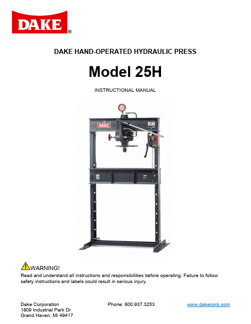
Dake CorporationPhone: 800.937.3253DAKE HAND-OPERATED HYDRAULIC PRESSModel 25HINSTRUCTIONAL MANUALWARNING!Read and understand all instructions and responsibilities before operating. Failure to follow safety instructions and labels could result in serious injury.TABLE OF CONTENTSDAKE STANDARD LIMITED WARRANTY (2)RETURN & REFUND POLICY (4)SAFEGUARDING THE POINT OF OPERATION (5)SPECIFICATIONS (6)SAFETY (6)SET UP (8)FILLING PRESS WITH OIL (8)OPERATION (9)CONTROLS (9)MAINTENANCE (9)LUBRICATION (9)TROUBLESHOOTING (9)EXPLODED VIEW & PARTS LIST (10)ORDERING INFORMATION (15)DAKE STANDARD LIMITED WARRANTYFinished MachinesDake warrants to the original purchaser the finished machine manufactured or distributed by it to be free from defects in material and workmanship under normal use and service within 1 year (12 months) from the delivery date to the end user.PartsDake warrants to the original purchaser the component part manufactured or distributed by it to be free from defects in material and workmanship under normal use and service within 30 days from the delivery date to the end user.The standard limited warranty includes the replacement of the defective component part at no cost to the end user.Sale of Service (Repairs)Dake warrants to the original purchaser the component part repaired by Dake Corporation at the manufacturing facility to be free from defects in material and workmanship under normal use and service within 90 days from the return date to the end user, as it pertains to the repair work completed. The standard limited warranty includes repair of the defective component part, at no cost to the end user.Warranty ProcessSubject to the conditions hereinafter set forth, the manufacturer will repair or replace any portion of the product that proves defective in materials or workmanship. The manufacturer retains the sole right and option, after inspection, to determine whether to repair or replace defective equipment, parts or components. The manufacturer will assume ownership of any defective parts replaced under this warranty.All requested warranty claims must be communicated to the distributor or representative responsible for the sale. Once communication has been initiated, Dake Customer Service must be contacted for approval:Phone: (800) 937-3253Email: ****************************When contacting Dake, please have the following information readily available:- Model #- Serial #- Sales Order #Purchasers who notify Dake within the warranty period will be issued a Case number and/or a Return Material Authorization (RMA) number. If the item is to be returned per Dake’s request, the RMA number must be clearly written on the exterior packaging. Any item shipped to Dake without an RMA will not be processed.Warranty Exceptions:The following conditions are not applicable to the standard limited warranty:(a) Part installation or machine service was not completed by a certified professional, and is notin accordance with applicable local codes, ordinances and good trade practices.(b) Defects or malfunctions resulting from improper installation or failure to operate or maintainthe unit in accordance with the printed instructions provided.(c) Defects or malfunctions resulting from abuse, accident, neglect or damage outside of prepaidfreight terms.(d) Normal maintenance service or preventative maintenance, and the parts used in connectionwith such service.(e) Units and parts which have been altered or repaired, other than by the manufacturer or asspecifically authorized by the manufacturer.(f) Alterations made to the machine that were not previously approved by the manufacturer, orthat are used for purposes other than the original design of the machine.RETURN & REFUND POLICYThank you for purchasing from Dake! If you are not entirely satisfied with your purchase, we are here to help.ReturnsAll Dake manufactured / distributed machines, parts and couplings include a 30-day return option. These policies are valid from the date of final shipment to the end user.To be eligible for a return, the item must be unused and in the same condition as received.All requested warranty claims must be communicated to the distributor or representative responsible for the sale. Once communication has been initiated, Dake Customer Service must be contacted for approval:Phone: (800) 937-3253Email:****************************Once the return request has been approved by Customer Service, a representative will supply a Return Material Authorization (RMA) number. The returned item must have the provided RMA number clearly marked on the outside packaging. Any item received without an RMA number clearly visible on the packaging will not be processed.An RMA number can only be provided by the Dake Customer Service team and must be obtained prior to the return shipment.RefundsOnce the item has been received and inspected for damages, a representative will notify the requestor referencing the provided RMA number.If the return is approved, a refund will be issued to the original method of payment, less a 20% restocking fee. The restocking fee may be waived if an order is placed at the time of return with like-value merchandise.Transportation costs are the responsibility of the end user and will not be credited upon return approval.Any item that is returned after the initial 30 days or has excessive/obvious use will not be considered for a full refund.SAFEGUARDING THE POINT OF OPERATIONANSI B11.2 - Hydraulic Power Presses -Safety Requirements for Construction, Care, and UseIt is important that Dake press users have a clear understanding of their responsibility involving the care and use of their Dake hydraulic press, including point-of-operation safe guards. Dake strongly recommends that Dake press users obtain a copy of the current American National Standard Institute (ANSI) B11.2 standard, for a more complete understanding of their responsibilities.ANSI B11.2 states the following, relative to point of operation safeguarding:“Normally, only the employer (press user) can determine the requirements of the press productions system components, including the dies and methods for feeding. Therefore, the employer is ultimately responsible to designate and provide the point-of-operation safeguarding system.”The standard also discusses additional responsibilities of the employer. Some of the key responsibilities are:•The employer is responsible for the safety, use, and care of the hydraulic power press production system.•The employer is responsible to consider the sources of hazards for all tasks to be implemented on the hydraulic power press production system.•The employer is required to eliminate or control identified hazards in the scope of their work activity. •The employer is responsible for the training of personnel, caring for, inspecting, maintaining, and operating hydraulic press production systems to ensure their competence.•The employer is responsible to provide and ensure that point-of-operation safeguarding is used, checked, maintained, and where applicable, adjusted on every production operation performed on a press production system.A complete and current copy of the ANSI B.11.2 standard can be obtained by contacting the following:American National Standards Institute1430 BroadwayNew York, NY 10018AMT – The Association for Manufacturing Technology7901 Westpark DriveMcLean, VA 22102SPECIFICATIONSNumber 907001 Ram travel 5” Capacity25 tons Screw travel 5” Width between uprights33-1/2”Height 76” Width between table channels 5 -3/16” Weight460 lbs Min ram to table 4” Base 42-1/2” x 30”Max ram to table39”In the space provided record the serial number and model number of the machine. Thisinformation is only found on the black and gold Dake tag shown below. If contacting Dake this information must be provided to assist in identifying the specific machine.SAFETYThis is the safety alert symbol. When you see this symbol on your press be alert to the potential for personal injury.Employer is responsible to perform a hazard/PPE assessment before work activity.Follow recommended precautions and safe operating practices.Additional Warnings:• Carefully read all safety messages in these instructions and on your press safety signs.• Keep safety labels in good condition. Replace missing or damaged safety labels. • Employer is responsible to perform a hazard/PPE assessment before work activity. • Do not alter this press from its original design.• Do not make repairs or adjustments to any hydraulic system unless you are competent or working under competent supervision. • Only use Dake original parts. Serial No.Model No. Install Date:• This machine is intended to be operated by one person. This person should beconscious of the press ram movement not only for themselves but also for persons in the immediate area of the machine.• Tag out procedures must be followed by authorized employees as per OSHA• Hydraulic – Relieve all hydraulic pressure before servicing the press. Turn the red release handle to relieve the pressure• Spring Pressure – Clamp ring on bottom of piston must be in place before removing cylinder• Hoist and table channel – always place table pins under the table channels then install the remaining pins. Always release pressure on the cable before using pressLabel Placement ViewSET UPFor shipping convenience, the gauge, pump handle, hoist crank, screw nose and base angles were removed from the press. Assemble these parts to the press in the following order:1. Bolt the base angles to the uprights using the four bolts and nuts furnished. Shoulder thebase angles against the stops on the uprights.2. The press should be set on a level floor with the base angles touching the floor at allpoints, using shims where necessary. Then secure the base to the floor using the four, 1/2” bolts included.3. Install the pressure gauge using the hydraulic sealant to ensure a sealed fit.4. Insert the pump handle into the handle socket and fasten in place by means of the setscrew on top of the handle socket.5. CAUTION! Place the hoist crank on the lift drum shaft. The table is raised to thedesired height by turning the crank after removing the table pins. Check to make sure the hoist cable is tracking correctly. Run the table channels from top to bottom. The cableshould be on each of the two upper pulleys and should track back and forth on the cable drum.a. Place the table pins under the table before releasing the hoist crank whenpositioning the table channels for cable tracking, servicing, or set up for desiredwork operating. Be sure all table pins are fully inserted in place before applyingpressure. Always remove or release pressure on the cable before pressure isapplied by turning the hand crank counterclockwise until slack forms in the cables.FAILURE TO DO SO WILL CAUSE DAMAGE TO THE HOIST.b. If a tracking problem exists, contact the Dake factory for instructions.6. Fasten nosepiece to the end of the screw using the thumbscrew included.FILLING PRESS WITH OILRecommended to replace hydraulic oil every 6 months of machine use.IMPORTANT! ONLY FILL WITH NEW, CLEAN, LIGHT HYDRAULIC OIL. UNDER NO CIRCUMSTANCES USE DIRTY OIL.1. Use Mobil DTE 24 or equivalent.2. Filter the oil to remove any possible dirt or other contaminant.3. Move the piston to its maximum upper position.4. Fill the reservoir with 2-1/2 quarts of oil.5. The press should be filled through Item No. 29 (Part No. 589).6. Close the Release Valve (Part No. 716682) and pump oil into the work head until oil isvisible in the standpipe.a. This will remove all air from the chamber above the piston.If oil leaks by the piston, the reservoir should be drained and refilled with the piston in the maximum upper position.OPERATIONCONTROLSHand Crank: (Items No. 57, 58 / Table Spacer, Handle) on the side of the press is to assist in lowering and raising the table of the press once the table pins are removed. Do not forget to replace the pins once you have the table at the desired height.Head Positioning Handwheel: can be loosened to allow the head to move along the upper frame track and can be positioned at any length on the top frame. After in position, tightening the handwheel completely will keep the head in place.Handle: (Item No. 49 / Handle) The pressure supply source and is manually operated with up and down motion.IMPORTANT! Always pump the piston down 1/2” before the nose piece encounters the work. Damage to the piston may occur if not pumped before meeting the work. Release Valve Handwheel: (Item No. 41 / Release Valve Handwheel) Releases the pressure to let the ram return to its raised position. Always keep the valve firmly closed when operating the press until you want to release the pressure.Screw Handwheel (Item No. 33 Screw Handwheel Assembly) raises or lowers the ram screw in and out of the piston assembly. Always keep the portion of the screw extending out of the piston as short as possible. Instead of overextending the screw it is recommended to raise the table rather than running the screw out of its limit of travel. NEVER EXCEED THE RECOMMENDED STROKE OF 5 INCHES FOR THIS PRESS. EXCEEDING THE STROKE WILL CAUSE DAMAGE TO THE INNER PACKINGS.MAINTENANCERecommended to replace hydraulic oil every 6 months of machine use. See “FILLING PRESS WITH OIL”section for instructions.LUBRICATION•Keep all working parts of the press well-oiled for easier operation.•Keep a light film of oil over the entire surface of the ram to prevent rust. TROUBLESHOOTINGSYMPTOM CAUSE SOLUTIONOil leaking from piston oil seal. 1) Reservoir (Part No. 963) isover filled.2) Piston Packing (Part No. 969/ 17976) is worn or damaged.1) Drain excess oil.2) Replace Piston Packing.Press will not hold pressure. 1) Check Ball (Part No. 586) iscontaminated.2) Ball and Seat (Part No. 586)have poor contact.3) Piston Packing (Part No. 969/ 17976) is worn or damaged.1) Remove and cleanCheck Balls and Seats.2) Reseal Ball on Seat.3) Replace Piston PackingPress will not build rated tonnage. 1) Pump Plunger (Part No. 554)leather is worn or damaged.2) Check Ball (Part No. 586) iscontaminated.3) Ball and Seat (Part No. 586)have poor contact.4) Piston Packing (Part No. 969/ 17976) is worn ordamaged.5) Gauge (Part No. 71265) isdefective.1) Replace Pump Plungerleather.2) Remove and cleanCheck Balls and Seats.3) Reseal Ball on Seat.4) Replace Piston Packing.5) Replace Gauge.Oil leaking from pump plunger. 1) Packing Nut loose (Part No.551).2) Worn Packings. (Part No.573)1) Tighten Packing Nut.2) Replace PumpPackings.Oil leaking from release valve rod. 1) Valve Rod Packing Nut isLoose. (Part No. 576)2) Packings are worn. (Part No.573)1) Tighten Packing Nut.2) Replace Valve RodPackings.Pump handle drifts up. 1) Defective Check Ball (PartNo. 586).2) Defective Check Ball Spring(Part No. 579)3) Clean Check Ball andreseat.4) Replace Spring.Ram will not return. 1) Return Spring damaged.(Part No. 968)2) Piston is bent or damaged.(Part No. 964)3) Piston Packing is defective.(Part No. 969 / 17976)1) Replace Spring.2) Replace Piston.3) Replace Piston Packing*If oil leaks from around ram but there is no pressure loss than the reservoir has been overfilledEXPLODED VIEW & PARTS LISTHAND PUMP ASSEMBLYItemNo. Part Name Part No. Qty ItemNo. Part NamePartNo. Qty1 Pump Body 546 1 13 Pump Plunger 554 12 Ball Valve 5863 14 Handle Socket Pin 594A 33 Hex Cap Screw(Nylock 1/4”-20 x 1/2") 28297 1 15 Valve Release Rod 1129 14 Washer # 12 Flat 43629 1 16 Valve Rod Packing Nut 576A 15 Pump Plunger Leather 599 1 17 Valve Rod Packing 987 76 Check Valve Spring 579 1 18 Pipe Plug (3/8”) 588 17 Tube Fitting, Poly-Tite 71413 1 19 Socket Set Screw(3/8”-16 x 5/8”) 43589 18 Pump Packing 573 7 20 Pump Gasket 591 19 Pump Packing Nut 551A 2 41 Release ValveHandwheel 10631 110 Handle Socket 550 1 F1 Screw (1/4”-20 x 1/2”) 43301 111 Handle Socket Link 555 1 F2 1/4" Flat Washer 43631 112 3/8” Retaining Ring 43972 6WORKHEAD ASSEMBLYItem No. Part Name PartNo. Qty 21 Cylinder Gasket 998 1 22 Cylinder 960 1 23 Piston Leather (Serial No. < 192522) 969 123A Packing Ring (Serial No. >192523) 17976 124 Piston Assembly (Serial No. < 192522) 701800 124A Piston Assembly (Serial No. > 192523) 716221 124A Piston 964 1 26 Ram Spring 968 1 27 Pipe Plug (1/2” NPTF) 596 128 Pipe Fitting Street Elbow (1/2”) 45388 129 1/8” Pipe Plug 589 1 30 Oil Seal 999 1ItemNo.Part Name Part No. Qty 31 Piston Bumper 996 1 32 Clamp Ring982 2 33Screw Handwheel Assembly716682 1 33A Hub, Handwheel 86536P 33B Handle86556P 33C Pin, Spiral or Roll 74923 34 Screw971 1 35 Screw Nose986 1 35A *If needed - Thumb Screw(1/4”-20 x 3/4") 43618 1 36 Reservoir963 1 FA3Air Vent Tube (1/4” x 3”)632 1 FA4 Pipe Plug (1/4”) NPTF 1567 1 FA5 Hex Nut (3/8”-16)43912 2 FA6Hex Cap Screw (2-3/4 x 3/8”-16)43335 2 N/ARepair Kit – Cylinder & Hand Pump Assembly (Items: 5, 8, 17, 20, 21, 23, 30, 31)701290-GENERAL ASSEMBLY PARTS LISTItemNo.Part Name Part No.Qty ItemNo.Part Name Part No.Qty37 Hand Gauge 71265 1 56 Table Spacer 86487 4 37Special Bushing813841F7Screw (3/8”-16 x 6”)433412 38Tube Fitting (37°)12521F8Lock Washer (3/8”)436452 39Dake Nameplate 810021F9Hex Nut (1/2”-13)43916841Release ValveHandwheel106311F10Lag Screw(1/2”-2 x 2-1/2”)72355442Table Plate9662F11Washer (1/2”)43634443Table Pin9814F12Soc. Head Cap Screw(1/2”-13 x 3”)24565144Table Channel7010202F13Hex Cap Screw(1/2”-13 x 1-3/4”)43350445Frame only7001341F14Channel WasherCasting25H138P246Base Angle9782F15Hex Cap Screw(1/2”-13 x 1-1/2”)43349447Tube Fitting(3/8” NPTF, 37°)12512F16Lock Washer (1/2”)436478 48Tube Assembly7001331F17Bolt (1/2"-13 x 6x1/2”)799824 49Handle2181F18Hex Nut (3/8”-16)43912450Pulley602-25H2F19Socket Cap Screw(1/2”-13 x 1-1/4”)434703 51Plastic Tube (1/4”)677611A1 Work head Assembly907006152Tube Fitting (1/8”NPTF, Straight) 714131A2 Table Hoist Assembly– Includes Crank700112153Hoist Spacer9972A3 Hand Pump Assembly 700887154Cable 9881N/A Tag – No oil inreservoir 79956155 Cable Clamp 583 4 N/A Label –Made in U.S.A. 76936 1HOIST ASSEMBLYItemNo. Part Name Part No. QtyItem No. Part Name Part No. Qty 58 Handle1000 1 64 Hex Cap Screw (3/8”-16 x 2-1/2”) 43335 2 59 Worm Shaft 384 1 66 Drum Shaft 724 1 60 Retaining Ring 27437 2 67 Drum Key 737 1 61 Worm Key 47364 1 68 Worm Gear 736 1 62 Worm385 1 69 Cable Drum 723 1 63Hoist Frame725170Retaining Ring439921Please contact factory for current prices.ORDERING INFORMATIONParts are available for direct purchase from Dake or through a distributor. When placing a parts order, you will need to provide the part number, name of part, and model number. All parts shipped F.O.B. Factory in Grand Haven, MI.。
Y32-1000S-说明书讲解
特别说明:1.新机启动时,应点动检查电机转向的正确性。
2.新机或停机较长时间后,重新起动时,应点动4~5次后,再连续运行。
3.按规定要求在润滑点加注润滑油。
4.设备工作时,严禁身体任何部分进入工作区。
5.严禁超负荷超行程工作。
6.液压油的质量状况对设备工作和元件寿命影响很大,需经常检查油液状况和按规定更换液压油。
7.除特别制造外,设备不适宜在粉尘环境中使用,若工作环境粉尘较大,请特别说明。
目录一、用途和特点 (3)二、主要技术规格 (3)三、结构概述 (4)四、操作要领 (5)五、安装与试车 (5)六、维护保养和安全操作注意事项 (6)七、密封件一览表 (8)八、附图 (9)一、用途和特点本结构简单, 动作灵敏可靠, 操作安全方便, 可实现电动调整和半自动工作两种操作方式。
半自动工作中, 活动工作台可完成快速下行、加压、自动回程、回程停止等整个工作循环。
生产率高, 能耗低。
二、主要技术规格序号项目单位数据1 主油缸公称压力kN 100002 主油缸液体最大工作压力MPa 204 退料缸行程mm 1505 退料缸公称力kN 1506 活动横梁最大行程mm 8007 活动横梁下平面到工作台面最大距离mm 14008 活动横梁行程速度空载下行mm/s 250回程mm/s 2009 工作台有效面积左右mm 1400前后mm 135010 轮廓尺寸左右mm ≈5600前后mm ≈6900高度mm ≈645011 电机功率kW三、结构概述:本机主要由机身、主油缸、液压系统、油箱、泵装置等构成。
各部份如外形图所示:四、操作要领参照面板布置图,将全部自动开关置于“开”,依次按“油泵起动”按钮,待4个电动机正常工作之后,再进行下列操作。
本机可以有两种操作方式:1.将“自动/点动”选择开关置于“点动”时,按“主缸点动上行”则主油缸上行,松手则停止;按“主缸点动下行”则主油缸下行,松手则停止。
按“下缸点动上行”则下油缸上行,松手则停止;按“下缸点动下行”则下油缸下行,松手则停止。
1000辊锻机技术要求

备注:甲方负责车间水、电、气到乙方指定位置〔接口〕,接口到设备之间水、电、气管路由乙方负责,接口以外由甲方负责。
Φ1000 自动辊锻机组1、设备用途φ1000 辊锻机及辊锻机械手,用于曲轴、前轴、刮板、销轴、转向节等多品种批量辊锻,同时设备能够三班连续工作,适应大批量生产的需要。
2、供货范围2.1、φ1000 自动辊锻机辊锻机械手一台 一台序号 名 称 规格型号 数量(台/套) 备 注 1 Φ1000 自动辊锻机组 理论中心距 1000mm 1 2辊锻机械手1上述设备为机械系统、电控系统、气动系统、液压系统成套供货;且包括设计、选购、制造、包装、指导安装、调试和验收、质量保证和售后效劳、技术培训等工作内容。
3、Φ1000 自动辊锻机技术参数 3.1 根本要求: 3.1.1 所选设备必需是全的,设计先进合理,具有国际水平。
3.1.2设备配置和布局应满足生产工艺要求,设备接口稳定,数据传输准确,物流畅通。
3.1.3 运行牢靠,修理便利、易于维护和保养。
3.1.4 操作便利,运行费用低。
3.1.5 符合国家环保和安全卫生标准的要求。
3.1.6外观干净,构造布局合理紧凑。
3.2 设备工作环境:3.2.1工作车间环境温度:-5ºC ~45ºC。
3.2.2工作车间环境湿度:≤89%。
3.2.3循环供水:温度≤33ºC,压力≥0.3MPa。
自来水:0.1~0.2Mpa。
3.2.4电源:三相沟通电380 V〔±10%〕,50Hz〔±2%〕单相沟通电220 V〔±10%〕,50Hz〔±2%〕3.2.5压缩空气:0.5—0.7Mpa。
3.3电控系统技术要求3.3.1、设备设计应可实现自动、手动、调整等工作方式。
3.3.2、电控设备及沟通电动机的供电均承受三相五线AC380V/50HZ的沟通电源。
动力线和信号线要求分开或进展有效隔离敷设,防止电气干扰。
液压剪板机(操作介绍及其说明)说明书

目录1、前言———————————————————————— 22、概述—————————————————————————32.1主要用途及特性——————————————————32.2 安全使用注意事————————————————— 43、结构及技术参数————————————————————53.1机床的外形————————————————————53.2机床的主要结构及用途———————————————63.3机床的主要规格和技术参数—————————————74、机床的吊运及安装——————————————————84.1机床的吊运————————————————————84.2 机床的安装———————————————————94.3 电气接线————————————————————95、机床的加油及机床润滑————————————————105.1 油箱的加油———————————————————105.2 机床润滑————————————————————106、机床的液压系统分析—————————————————106.1液压元件的简述——————————————————106.2液压系统动作分析—————————————————137、机床的操作及调整——————————————————187.1 机床的控制符号说明———————————————187.2 机床的操作———————————————————188、机床的维修、保养与故障排除—————————————238.1液压系统————————————————————238.2 机械部件的检查—————————————————238.3 安全阀的调整——————————————————249、技术服务—————————————————————2410、易损件明细表———————————————————25前言剪板机是借于运动的刀片和固定的刀片,采用合理的刀片间隙,对各种厚度的金属板材施加剪切力,使板材按所需要的尺寸断裂分离的设备。
四柱液压机说明书
Y32-500/1000X1500 四柱液压机使用说明书Y95.SY注意:禁止在阅读本《使用说明书》之前操作机床!前言为使您能尽快熟悉本机器的结构和性能,掌握对本机器的吊运、安装、调试、使用、维护和维修等操作的正确方法,我们随机配备了《使用说明书》。
您在对机器进行各项操作之前,请务必读懂《使用说明书》的相关内容,以免造成不必要的损失。
《使用说明书》是帮助您正确使用、维护和维修本机器的重要资料,是本机器的组成部分,任何由于违反《使用说明书》中的说明或规定而引起的损坏或事故,责任不在制造方。
因此在本机器未被停用、处理之前,请您妥善保管,以免给您的工作带来不便。
《使用说明书》我们有更正的权力。
用户不可擅自复印、扩散,违反该规定而引起的不良后果由用户负责。
在编写本说明书时,我们非常认真,并认为其中所提供的信息是正确可靠的,但难免会存在疏漏或不足之处,希予谅解,并真诚地欢迎您提出宝贵意见.一、机器的液压系统1.1、概述:本机液压系统结构简单,调整、维修方便,工作平稳、可靠。
两台油泵电机组、油箱位于机架后部,液压阀中除了充液阀直接固定于主油缸顶部外,其余都集成在油箱后部的一个阀块上,通过管道将各泵,阀连接起来组成系统。
本机油箱容积520升左右,再加上油缸和管道容积总共需要加油570升,约需3桶多油,建议用46#抗磨液压油,使用环境温度0-45℃。
本机液压系统可实现对油泵的启动,停止,活塞杆快速驱近及压制,保压,卸荷,返程等工况。
本机油缸达到额定公称力3500KN时,系统压力25Mpa。
在以下叙述中请对照液压原理图,各阀和各个电磁铁所列序号与原理图均一一对应。
液压原理图见图8-1,液压阀块安装图见图8-21.2、工作原理:1.2.1、启动:按下“启动”按钮,电机带动油泵转动,各电磁铁不带电,两台油泵打出的油经由阀C1、C2回油箱,油泵空运转,油泵正确旋转方向应为面对油泵伸出轴看去为顺时针。
1.2.2、停止:按下“停止”按钮,电机油泵停止转动,各电磁铁不带电,活塞杆保持原来的位置。
- 1、下载文档前请自行甄别文档内容的完整性,平台不提供额外的编辑、内容补充、找答案等附加服务。
- 2、"仅部分预览"的文档,不可在线预览部分如存在完整性等问题,可反馈申请退款(可完整预览的文档不适用该条件!)。
- 3、如文档侵犯您的权益,请联系客服反馈,我们会尽快为您处理(人工客服工作时间:9:00-18:30)。
目录一、外观图二、用途和特点三、主要技术规格四、结构概述五、液压系统概述六、电气系统概述七、安装与试车八、维护保养和安全操作九、故障和消除方法十、易损件表附图1、移动工作台俯视图2、滑块仰视图3、主缸结构图4、侧缸结构图5、顶出缸结构图6、液压垫缸结构图7、缓冲缸结构图8、 YT27-2000C-30A阀块结构图9、 YT27-2000C-30B阀块结构图10、YT27-2000C-30C阀块结构图11、JTDB32DYF4/3-10a插装阀块结构图12、JTDB32YS2/2-10c插装阀块结构图13、JTDB50ZS6-10b 插装阀块结构图附以下产品图1、总装配图 (0000 1/3)2、液压原理图 (0000 2/3) (共2张)3、电气原理图 (0000 3/3))(共21张)4、操纵板接线图(6000 1/5)5、分线盒线号布置图(6000 2/5)6、动力机构接线图(6000 3/5)7、电气互连图(6000 4/5)8、电气布置图(6000 5/5)9、基础图 (YT27-2000C-0100)YT27-1000U 使用说明书YT27-1000U-SM 共32页第3页一、外观图YT27-1000U使用说明书YT27-1000U-SM 共32页第4页二、用途和特点本机主要适用于金属板件的拉伸、弯曲、翻边、成型和复杂箱体及大曲面零件拉伸及成形等工艺。
本机具有以下特点:1、本机的控制系统有定压和定程两种工作方式,通过操纵面板上的选择开关切换。
工作方式包括微调整、寸动、半自动和全自动四种工艺动作。
2、本机的液压控制系统采用插装式集成阀,先导电磁阀采用进口德国力士乐公司产品,主泵采用进口德国力士乐公司公司产品,提高了动作的可靠性及使用寿命,同时减少了噪音和液压冲击。
3、本机的电气控制系统采用了日本OMRON公司生产的PLC可编程控制器,可实现机床各种工艺动作循环。
该系统使控制更为灵活,动作准确可靠。
4、本机的机身采用组合框架式结构,机身有足够的强度和刚度,机械精度保持性好。
5、油缸采用进口奥地利爱科品牌产品的密封件,提高了密封效果和寿命,确保密封性能可靠。
6、本机的动力部分安装于机身顶部,占地面积小,结构紧凑,外形美观。
7、本机设有油位、油温、滤油器堵塞及润滑等多种故障指示灯和故障报警功能,以便于各种条件下的工作需要。
8、本机的液压系统设有液压油过滤,加热和冷却系统,保证机床正常工作油温在15--60°C之间。
9、本机设有滑块上死点锁紧装置,防止滑块下滑,保护换模和维修人员的安全。
(五)润滑装置本设备应采用独立的自动循环带监控的强制润滑系统,主要由电机、齿轮泵、溢流阀、压力表、分流阀及油箱等组成,启动由操纵面板上的转换开关控制。
五、液压系统概述(一) 概述本机的液压系统由能量转换装置(泵和油缸)、能量调节装置(各种阀组件)以及能量输送装置(油箱、管路)等组成,在电气系统的控制下可完成各种工艺动作循环。
(二) 本机设有以下工艺动作可供选择:压机操作方式有微调整、寸动、半自动和全自动四种操作方式。
分定程和定压两种工作方式。
压机能完成以下工艺动作:1. 调整调整动作又称“点动”,操作相应的功能按钮完成相应的动作,每按一次按钮完成相应动作的一次点动。
主要用于调整模具时使用。
手按压按钮才有相应动作,抬手则此动作停。
2. 一般工艺动作(带顶出和不带顶出)滑块快速下行——滑块慢速下行并加压——滑块持续加压(保压)——滑块泄压——滑块慢速回程——滑块快速回程——滑块回程减速,液压垫顶起——滑块回程停止,液压垫继续顶起——液压垫顶出停止并延时——液压垫退回——液压垫退回停止3. 拉伸工艺动作滑块快速下行——滑块慢速下行并加压——滑块下行停止——滑块泄压——滑块慢速回程——滑块快速回程——滑块回程减速,液压垫顶起——滑块回程停止,液压垫减速顶起——液压垫顶起停止并延时4. 冲裁工艺(带顶出)滑块快速下行——滑块慢速下行——滑块泄压——滑块快速回程——滑块回程减速,缓冲缸复位,液压垫顶起——滑块回程停止,液压垫继续顶起——液压垫顶出停止并延时——液压垫退回——液压垫退回停止(三) 液压原理动作说明(见附产品图样00002/3)首先接通电源,启动M1电动机,使润滑油泵供油,润滑泵的油压为0.2~0.8MPa。
当导轨上有足够润滑油后,再依次起动M2、M3、M4、M5、M6、M8、M9、M10电动机,使相应的油泵运转。
各压力阀的设定压力及调整范围(参见液压原理图)。
以下就拉伸工艺动作循环做详细介绍:机器运动之前,将选择开关放置于拉伸工艺动作上,上滑块处于回程停止LX1处,下滑块(液压垫)处于顶出停止位置LY1处。
1. 空负荷运转接通电源,按要求依次启动各电机,使系统处于空循环状态。
2.滑块快速下行按压工作按钮后,电磁铁YA11、YA12、YA14、YA21、YA23、YA24 、YA33、YA35动作,此时高压泵输出油进入主缸及侧缸上腔,同时回程缸的油液排回油箱,充液阀在自吸状态下向主缸及侧缸补油。
此时滑块快速下行。
3. 滑块慢速下行并加压:当滑块快速下行至减速下行发讯点LX3位置时,前一动作的电磁铁YA23断电复位, 其余电磁铁继续通电。
此时主缸及侧缸回程腔油液克服支撑阀块的调定压力排油(支撑阀调定压力以上滑块不下溜为好,不宜过高),滑块慢速下行并加压。
4.滑块下行停止:当下行至减发讯点LX5位置时, 前一动作中的电磁铁YA12、YA14断电复位,其余电磁铁继续通电,滑块下行停止,时间继电器KT1开始工作(延时时间可调)。
5.滑块泄压:当KT1延时到点后,此时前一动作电磁铁全部断电复位, 电磁铁YA36通电,主缸及侧缸压力逐渐下降,油泵空循环,充液阀在控制油的作用下开启,时间继电器KT2开始工作(延时时间可调)。
6.滑块慢速回程:当KT2延时到点后,此时前一动作电磁铁继续通电,电磁铁YA11、YA22、YA25、YA36通电,泵来油通过各阀进入回程缸,主缸及侧缸上腔油液通过充液阀排回油箱,此时滑块处于慢速回程状态。
7. 滑块快速回程:当滑块回程到LX4发讯点,LX4发讯,此时前一动作电磁铁继续通电,电磁铁YA12、YA14通电,泵来油通过各阀进入主缸回程腔,主缸及侧缸上腔油液通过充液阀排回油箱,此时滑块处于快速回程状态。
8.滑块回程减速,液压垫顶出:当滑块回程到LX2发讯点, LX2发讯,前一动作中的电磁铁YA12、YA14断电复位,其余电磁铁继续通电,电磁铁YA44通电,此时滑块回程减速,高压泵(H)来油通过阀组进入顶出缸,液压垫快速顶出。
9.滑块回程停止,液压垫继续顶起:当滑块回程到达LX1发讯点,LX1发讯,滑块回程停止。
前一动作中的电磁铁YA44继续通电,其余电磁铁断电复位。
液压垫继续顶起。
10. 液压垫顶起停止并延时当液压垫运行至LY1位置时,所有电磁铁断电复位,液压垫顶起停止。
其它动作:(1) 一般工艺动作(带顶出和不带顶出)(2) 冲裁工艺(带顶出)(3) 调整动作(4) 其他以上各种动作请参照液压原理图和动作表,故叙述从略。
YT27-1000U使用说明书YT27-1000U-SM 共32页第9页六. 电气系统概述(一)概述本机动力电路采用三相交流380V、50HZ电源;控制电路电压为交流220V,通过控制变压器得到;电磁铁动作电路为直流24V,通过直流电源得到。
本机设有专用的电气控制箱和电气操纵箱,电气控制箱内置总电源开关、接触器、热继电器和直流电源等各种电气元件(具体请查看电气设备清单)以及可编程序控制器、继电器等,主要完成对电机的控制、保护和对压机的集中控制。
电气操纵箱置于主机右前支柱内,在其操纵面板上装有各种控制按钮、旋钮、油温表和触摸屏等操作与指示器件。
考虑到压机操作的方便和安全,本机设有前,后移动操作台,上设双手工作按钮、紧急停止按钮、并且在机身上装有蜂鸣器,在半自动的工作方式下及工作台移动时进行报警提示。
本机控制系统采用日本欧姆龙公司CJ系列PLC,利用PDC15、AD081、DA081和CTO21模块进行过程控制和摸拟量控制,同时采用触摸屏进行集中显示和控制。
(二)电气铭牌数据电压: 380 V相数:三相频率: 50 Hz总功率: 366 KW总熔断器额定电流:800 A设备防护等级: IP43(三) 操作说明1.动力电路1)Q F0为总电源开关,合上QF0后接通三相电源。
2)按下SB3、SB2可实现对各油泵电机的起停控制。
2.主机工作电路根据压制工艺的要求,本机具有调整,寸动,半自动,全自动四种工作方式。
在半自动中有冲裁,拉伸,带顶出、不带顶出一般工艺动作。
主机工作方式时,选择旋钮SA2扳至“主机”位置。
1)调整/寸动:将旋钮SA9搬于“调整”或“寸动”位置,按压相关按钮,即可得到与该按钮对应的动作,调整时为点动动作,寸动时可以完成一个连续的动作;调整方式可使压机的工艺动作实现点动。
2)半自动:将旋钮SA9搬于“半自动”位置,在满足压机允许工作条件下,分别操纵对应发讯元件,可实现与之相对应的半自动循环。
3)全自动:将旋钮SA9搬于“全自动”位置,在满足压机允许工作条件下,分别操纵对应发讯元件,可实现与之相对应的全自动循环。
本机具有三种基本工艺动作:即一般和拉伸以及冲裁工艺动作(通过选择旋扭SA8实现),一般工艺动作又分带顶出和不带顶出两种方式。
(通过选择旋扭SA6实现)。
初始条件:一般工艺方式下要求上滑块回到上极限(SQ1发讯)或上限位位置(LX1发讯),液压垫退回到下极限(SQ13发讯)或下限位位置(LY2发讯);拉伸工艺方式下要求上滑块回到上极限(SQ1发讯)或上限位位置(LX1发讯),液压垫顶出到上极限(SQ12发讯)或上限位位置(LY1发讯);冲裁工艺(带顶出)要求上滑块回到上极限(SQ1发讯)或上限位位置(LX1发讯),液压垫顶出到上极限(SQ12发讯)或上限位位置(LY1发讯),左右缓冲都在上极限位置(SQ10a,SQ10b发讯)。
通过操作箱上的工作按钮SB12和或者移动操纵台上的双手按钮,都可以实现一个半自动循环,操纵箱和移动操纵台工作由触摸屏上的按钮来区分,当选择前台或者后台,或者前台后台都选择的时候为移动操纵台工作,都不选为操纵箱。
注意:当压机在半自动过程中因故障停止运行,应先将故障排除,然后在“调整”方式下将压机调试正常后,使压机回到半自动工作的初始位置,才可以重新进行半自动工作。
3.移动工作台当滑块处于插销位置,液压垫处于下极限时,将旋钮SA2搬至“工作台”位置,此时工作台允许动作。
工作台顶起到位后允许移动,动作包括移出和移入,将旋钮SA5扳至“顶起”位置时,按压SB5, 移动工作台移出,碰SQ5a或SQ5b 时移动工作台移出停止.按压SB4移动工作台移入,碰SQ8时移入停止,再将SA5旋钮旋至落下位置,SQ9a,SQ9b发迅时将旋钮SA2搬至“主机”位置,此时才对工作台完成一次移入移出操作.4.特殊动作在SA2置于“主机”位置时将旋钮SA4搬至“回位插销”位置时上滑块将自动回程至回程极限位置并插销。