parker接头、派克接头简介
派克接头
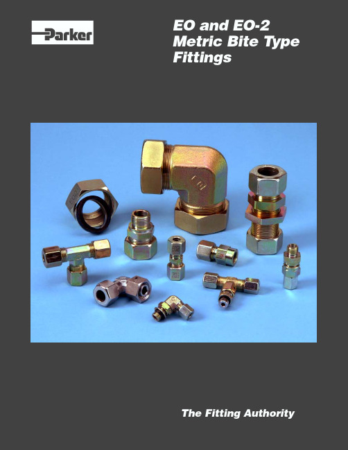
EO and EO-2 Metric Bite Type FittingsThe Fitting AuthorityInsert for Metal TubeEO Progressive Ring Fittings —IntroductionThe flareless bite type fitting was pioneered by Ermeto in Germany in the early 1930's. When Parker Hannifin acquired Ermeto, it introduced the EO fittings to the US. Today, the EO fittings are the most widely used bite type fittings in the world.The EO progressive ring fitting is a flareless metric fitting (for metric tube)that consists of a body, a progressive ring (ferrule)and a nut. On assembly, two cutting edges of the progressive ring “bite ” into the outer surface of the tube ensuring the necessary holding power and seal for high operating pres-sures.*The selection of LL, L or S design should be made by the user on the basis of intended system pressure. The pertinent maximum recommended working pressures are shown throughout this catalog in individual data charts of the various fitting configurations.demanding service conditions that exist in industry today. The original progressive ring, known as DPR, is now being replaced with the new generation, called PSR. PSR is stronger and features a “positive stop ” to eliminate over-tightening.The EO Nut. EO fitting nuts are either cold formed, hot formed or machined from cold drawn material. The cold forming and cold drawing operations provide a more tightly packed grain structure, thus improving the material's strength. In addition,cold forming significantly improves the fatigue properties or endurance limits of the nuts.Standard Material SpecificationsSteel fittings:EO tube fittings –Materials according to DIN 3859-1Stainless steel fittings:EO tube fittings –X6CrNIMoTi 17122 in accordance withDIN 17440 / EN 10088, material no.1.4571.Brass fittings:EO tube fittings –CUZN35Ni2 in accordance with DIN17660, material no. 2.0540.Elastomer seals:NBR (BUNA-N), FPM (Fluorocarbon)Surface Finish - Steel fittings:Standard LL SeriesBody, Nuts, and Rings– Zinc yellow chromateL+S Series Body and Nuts – Zinc yellow chromateProgressive Rings (DPR)– Zinc olive chromate Progressive Rings (PSR)– Zinc clear chromateShort codes for surface protection procedure in accordance with DIN 267 part 9 or DIN 50942.How EO Fittings Work: Function of Progressive Ring FittingsThe EO progressive ring fitting produces a low to high pressure,leak free connection of tubes and components in fluid systems.The basic function of the EO progressive ring is the controlled progressive bite of the ring into the tube due to a unique internal geometry.The front cutting edge has already started cutting into the tube before the second cutting edge starts. As soon as both cutting edges have cut the tube to the designed depth further advance is limited by the stop edge.Owing to the design of both cutting edges and stop edge all forces arising are equally distributed. This distribution along with the specially designed interior collar of the ring guarantees increased safety, particularly with regard to vibration and flex-ure stresses. The design and function of the progressive cutting ring ensure that service vibration loading is not present in the areas of the tubing where the bite is made.Fig. H1 — EO fitting components: Body, progressive ring and nutThe fittings and components listed in this catalog are intended solely for the assembly of connections for fluid applications.Three series of EO tube fittings (LL, L and S) and accessories are manufactured in accordance with DIN 2353 (summary) on the basis of decades of experience.*To ensure functional safety of EO tube fittings, only EO parts should be used in their assembly. Routing of tubes should be carried out in accordance with Parker/EO recommended prac-tices. Assembly instructions are available.Design and ConstructionThe three components of EO fittings are designed and manu-factured to produce a strong, reliable, leak-free joint upon proper assembly.The EO Body. EO fitting bodies are available in over thirty configurations. The shaped products (i.e., elbows, tees, crosses)are hot forged, then machined to the stringent EO fitting speci-fications. The forging process used by Parker further improves the strength and metallurgical properties of the fitting material.Straight products are made from cold drawn bar stock. The cold drawing operation ensures consistently tight dimensional toler-ances, as well as significantly improved strength.The EO Progressive Ring (Cutting Ring). EO progressive rings are precision machined with all dimensions and surfaces,particularly the critical bite edges, monitored on an ongoing basis. The rings are then heat treated in a manner that provides the hardness, strength, and toughness necessary to satisfy theSecond bite edgeFront bite edgeFig. F2 — How EO fittings workFitting Instructions:The life of a rotary fitting depends considerably in a stress-free line connection. Therefore, the direct connection with tube is to be avoided. For connection to hoses, the use of swivel nut fittings is recommended with short, straight lines (approx. length 5x hose O.D.). Thus, shocks and vibrations can be absorbed.Non-Return ValvesCharacteristics: Sealing is achieved by using a 90° cone with a packing washer of synthetic material. Valve has a lift stop which provides safe free outlet, shock-absorbing, muffled open-ing and no reduction of cross section. Maximum flow velocity not more than 8 m/sec (for higher flow velocities special tests are required).Opening Pressure: Approximately 1 bar (on request also 0.5-2 and 3 bar are available. Please specify on order). Tolerance of opening pressure is ±20%.Tube RecommendationsFor steel fittings:Seamless cold drawn steel tubes made from material St. 35.4 or from conditioned base material St. 37.4 in accordance with DIN 1630, state of delivery NBK (normal annealed) with tube outer and inner diameter tolerances in accordance with DIN 2391/ISO 3304. Max. hardness: HRB 75.For stainless steel fittings:Material no. 1.4571 and 1.4541Seamless drawn tubes made from austenitic, stainless steel materials no. 1.4571 and 1.4541, in accordance with DIN/EN/ ISO 1127. Max. hardness: HRB 90.These tubes are particularly recommended for tube fittings, since the tube outer diameter and wall thickness, tolerances correspond to those of steel tubes in accordance with DIN 2391/ISO 3304.For brass fittings:Seamless drawn copper tube made from material with short code SF-Cu F37 in accordance with DIN 1786.Tube wall thicknesses:In order to determine the necesary tube wall thicknesses for applications, refer to the calculated pressures provided in the tables for EO metric tubing. The calculated pressures DIN 2413-I are for static and DIN 2413-III for dynamic loads.The maximum wall thickness is based on the pressure holding capacity of the fitting. In some cases, the wall thickness of the tube might be too thin for reliable service and an insert must be used to prevent excessive tube collapse. See assembly sec-tion for recommended tube wall thicknesses.Plastic tube:EO fittings are suitable for use with various types of plastic tubes such as nylon, polyethylene, etc. When used with plastic tube, an insert (see page F14) must be used to prevent tube pull out due to tensile loading.Features, Advantages & Benefits•Visible Bite — The critical front bite of the progressive ring is clearly visible to tube fitters & inspectors. The presence of the recommended bite virtually eliminates any risk of catastrophic blow-off. This is a very important safety fea-ture.•Sealing Capability — EO fittings have demonstrated a remarkable ability to remain leak free under various ser-vice conditions ranging from sealing high vacuum and small molecules gases to high pressure hydraulic fluids.•Distributed Stresses — Stresses due to service flexural loading are distributed at several points in the joint, thus stress concentration in the bite is minimized.•Vibration Control — The rear bevel of the ferrule firmly grips tubing, thus dampening the effects of system vibra-tion in the joint.•Progressive Ring Design — The progressive ring design provides a second bite for improved reliability and higher working pressure capability. This design also decreases the risk of improper assembly because of the sharp, high torque rise which occurs when the fitting is properly tight-ened.•Envelope Size — EO fittings are relatively small and compact, making it a suitable selection for plumbing in limited or tight space.•Temperature Rating — EO fittings are suitable for sub-zero through elevated temperature applications. Service temperature rating is limited by the material chosen.•Compatibility — Since EO fittings can be manufactured from a wide range of metals, its compatibility factor with various fluids and atmospheric conditions is virtually limit-less. One simply has to select and specify EO fittings from an acceptable material that best satisfies the service conditions.•Tube Wall — EO fittings are suitable for use with light wall, medium wall, heavy wall, and extra heavy wall tubing.(Light wall tube may require support sleeve (VH), as shown in Assembly/Installation Section.)•Re-Usability / Remakeability — Joints can be disas-sembled and reassembled many times to facilitate system maintenance. This reduces the labor and material costs that would otherwise result from tube and fittings replace-ment.•Assembly — No expensive, complicated tooling is neces-sary to assemble EO fittings. Assembly is simple when the procedures described in the Assembly / Installation sec-tion are followed (see pages T24 - T27).•Materials — EO fittings can be manufactured from almost any metallic material. The more popular materials cur-rently used for EO fittings are: stainless steel, carbon steel, and brass. On request, the Tube Fitting Division will ma-chine EO fittings from other appropriate material specified by users.•Manufacture — EO fittings are manufactured under tight quality control which ensures that the product routinely satisfies or surpasses the requirements of the pertinent industrial standards.•World Wide Popularity — The bite type fitting design has worldwide acceptance and is especially popular in Europe.•Finish — Steel EO fittings have a zinc gold chromatefinish. This finish provides good corrosion protection.•Silver Plated Nuts — Stainless steel tube nuts are pre-lubricated with silver plated threads (size 15L-42L, 12S-38S). Thread galling is eliminated and assembly torque isreduced as much as 40 percent. This increases the speedand efficiency for stainless steel fitting assembly.•Availability — EO fittings are available as standard in overthirty different configurations, and as many as twenty-seven different size combinations in some configurations.•Configurations — Popular configurations for EO fittingsare shown in the Visual Index. Other configurations can bemanufactured on request.EO-2 Fitting System —IntroductionDesign and ConstructionFig. F3 — EO-2: Fitting body and functional nutThe EO-2 high pressure tube fitting generation is the most recentdevelopment of the Tube Fitting Division Europe. It was intro-duced in an effort to eliminate leakage in all fluid systems.The common feature of all EO-2 fittings is elastomeric seals onall joints. This assures leakfree operation without retightening— even under severe working conditions. Another break-through in bite-type technology is the simple assembly andcost-saving handling of the unique EO-2 Functional Nut.EO-2 is a true metric design according to 24° bite-type stan-dards such as: ISO 8434-1, DIN 2353 or DIN 3861. It covers allthree series (LL, L and S) of the broad EO tube fitting program.This resulted in a great acceptance with equipment manufac-tures that are targeting an absolute leakfree systems withoutsacrificing the convenience of using metric bite type fittings.Fig. F4 — EO-2: The metallic support of the sealing ring acts justlike an integrated preassembly tool.Elastomeric SealingThe elastomeric seal assures a hermetically sealed tube joint. Itis located in between the inner cone of the fitting body and thetube surface, thus blocking the only possible leak path. Due toits large cross-section, the seal effectively compensates for allmanufacturing tolerances on tube and fitting cone.The sealing effect is pressure supported which makes the EO-2 fitting suitable for high pressure applications. The staticcompression also eliminates air-ingress into the fluid system atunderpressure conditions.Elastomerically sealed EO-2 fittings do not require any retight-ening even in heavy-duty applications. Seal extrusion is pre-vented by proper housing without gaps or dead volume. Thesealing lip is bonded to a metallic support ring.Standard Material SpecificationsSteel fittings:EO-2 tube fittings–Materials according to DIN 3859-1Stainless steel fittings:EO-2 tube fittings–X6CrNIMoTi 17122 in accordancewith DIN 17440 / EN 10088, materialno. 1.4571.Brass fittings:EO-2 tube fittings–CUZN35Ni2 in accordance with DIN17660, material no. 2.0540.Elastomer seals:NBR (BUNA-N), FPM (Fluorocarbon)Surface Finish - Steel fittings:StandardLL Series Body, Nuts,- Zinc yellow chromateand RingsL+S Series Body and Nuts- Zinc yellow chromateRings (Progressive)- Zinc olive chromateShort codes for surface protection procedure in accordancewith DIN 267 part 9 or DIN 50942.How EO-2 Fittings WorkThe retaining ring bites into the tube in accordance to the proven bite ring principle. The elastomeric seal reduces the danger of over- or underassembly by a special EO-2 design feature: Before assembly there is a gap in between the flat surfaces of the retaining ring and the metallic support ring of the seal. As soon as the retaining ring has reached the proper incision depth, the gap closes, resulting in a sharp increase of assembly torque. This results in uniform and reliable fitting assemblies. The assembly result can easily be inspected by just checking if the gap is closed.The separation of sealing and holding functions to two separate elements finally allows a more effective solution of the over-and undertightening problems typically associated with bite type fittings.Integrated Assembly ToolThe metallic support ring of the seal is made of a specially designed material and heat-treatment to act as an assembly tool. This makes sure that the retaining ring securely cuts into the tube surface without damaging the sensitive inner cone of the fitting body.This unique feature of EO-2 fittings even allows direct assem-bly of tube without any additional pre-assembly process. An EOMAT machine (or other hydraulic tool) is strongly recom-mended to allow easy assembly of large dimension tube and drastically save total assembly time, effort and costs. The integrated assembly tool of EO-2 fittings even helps to save further costs and trouble when using an EOMAT-type preset-ting machine: As the presetting cone is only in contact with the elastomeric sealing lip, it cannot be worn out or damaged even after thousands of assemblies. This not only saves replace-ment costs but also avoids leakage problems caused by worn presetting tools.The Functional Nut Individual components such as seal or retaining ring cannot be forgotten, confused or assembled in the wrong orientation. Time and cost are saved by eliminating searching and arrang-ing the components to make up individual joints.Functional Nuts are completely interchangeable with the full range of EO tube fitting ends.After assembly and disassembly, the sealing ring can be replaced individually without cutting off the tube end. Tube RecommendationsFor steel fittings:Seamless cold drawn steel tubes made from material St. 35.4 or from conditioned base material St. 37.4 in accordance with DIN 1630, state of delivery NBK (normal annealed) with tube outer and inner diameter tolerances in accordance with DIN 2391/ISO 3304. Max. hardness: HRB 75.For stainless steel fittings:Material no. 1.4571 and 1.4541Seamless drawn tubes made from austenitic, stainless steel materials no. 1.4571 and 1.4541, in accordance with DIN/EN/ ISO 1127. Max. hardness: HRB 90.These tubes are particularly recommended for tube fittings, since the tube outer diameter and wall thickness, tolerances correspond to those of steel tubes in accordance with DIN 2391/ISO 3304.Tube wall thicknesses:In order to determine the necesary tube wall thicknesses for applications, refer to the calculated pressures provided in the tables for EO metric tubing. The calculated pressures DIN 2413-I are for static and DIN 2413-III for dynamic loads.The maximum wall thickness is based on the pressure holding capacity of the fitting. In some cases, the wall thickness of the tube might be too thin for reliable service and an insert must be used to prevent excessive tube collapse. See assembly sec-tion for recommended tube wall thicknesses.Plastic tube:EO-2 fittings are suitable for use with various types of plastic tubes such as nylon, polyethylene, etc. When used with plastic tube, an insert (see page F14) must be used to prevent tube pull out due to tensile loading.Fig. F5 — The unique Functional Nut allows easy handling and quick assembly.The unique Functional Nut simplifies handling of fitting compo-nents and helps to minimize storage and procurement costs. The sealing and retaining rings are combined as a pair and are inserted into the internal thread of the nut in such a manner that they cannot fall out, so that these three parts form one func-tional element.Features, Advantages and Benefits of the EO-2 Fitting SystemIn addition to the general advantages of the EO tube fitting system, the unique EO-2 fitting features offer even more spe-cific benefits:•Sealing Capability — An elastomeric seal forms the primary sealing element, thus assuring leak-free sealing.Even low-viscosity media such as water or gas are her-metically sealed. Hydraulic systems, therefore, do not “sweat” at fittings.•High Pressure Resistance — EO-2 fittings are rated up to Pmax 900 bar. Sealing lip and seal arrangements have both been designed so that the sealing effect is supported by system pressure. The interaction of the retaining ring and the integrated preassembly tool results in uniform and reliable fitting assembly.•Durability — The elastomeric seal does not require any retightening even after years of operation under severe working conditions.•Bite Control — The ideal bite depth is controlled by the fitting design rather than by the fitters force. Closing the gap at the end of the manual assembly, the fitter gets clear signal that setting is completed and the joint is ready for inspection.•Functional Nut — Individual components such as the retaining ring or seal cannot be lost, forgotten, confused or assembled in the wrong orientation. This dramatically saves assembly cost and helps to avoid dangerous as-sembly errors.•Assembly Cost — With less than 10 seconds cycle time on the EOMAT III/A (actual presetting process: 1.4 sec-onds), the cost of presetting EO-2 is extremely low.•Integrated Preassembly Tool — Each EO-2 Functional Nut comes assembled with an integrated assembly tool that makes sure that the retaining ring securely cuts into the tube surface without damaging the sensitive inner cone of the fitting body. This greatly reduces the danger of tube blow-off, even when using stainless steel tube.•Unlimited Presetting Tool Lifetime — When EOMAT machines are used for cost-efficient presetting, the preassembly tools do not wear out as they are only in contact with the rubber seal. This avoids dangerous blow-off which can result when traditional bite-type fittings are assembled using worn presetting tools.•Make-up — From the wrench-tight position of the preset EO-2 joint, one short pull on the wrench (approx. 1/6 to 1/4 turn) gives the assembly a quick high rise to required torque. EO-2 fittings have a solid “hit-home-feel” and excellent over-torque resistance.•Visible Inspection — There is no doubt if an EO-2 Func-tional Nut has been preset correctly or not. Inspection is as simple as checking if the gap between retaining ring and sealing ring is completely closed. The tube end does not have to be disassembled out of the fitting for bite inspec-tion.•No Phantom Leaks — Lubrication is not mandatory for the assembly of steel EO-2 fittings. The machine operator will not be irritated about lubricant coming out of the fittings once the hydraulic system gets hot.•Re-Usability / Remakeability — EO-2 fittings can be disassembled and reassembled many times. There is no wear or widening of the vulnerable inner cone. Damaged seals can easily be replaced. All spare DOZ-seals are marked by size-code (e.g.: 12-L).•On-Site Maintenance — For the maintenance and re-placement of EO-2 fittings a set of wrenches is sufficient.Additional in line components, such as test points (GMA), ball valves (KH) or T-fittings can be added to an existing assembly within minutes.•Interchangeability — The EO-2 Functional Nut can be used for the whole variety of the broad range of more than50 configurations in some 25 sizes of standard EO LL, Land S-series fittings. Changeover from Progressive ring or weld nipple is easy by the simple use of EO-2 Functional Nuts.•Reliability — Millions of EO-2 fittings are working trouble-free in applications like: Mobile construction equipment, stationary machine tools, hydraulic presses, plastic injec-tion molding machines, shipbuilding, offshore exploration, submarines, railway trains and military equipment. Leak-age does not occur on EO-2 pipework.•Trouble-Free — Regular bite type fittings allow typical assembly-errors such as: confusion of bite type ring mate-rial and size. Also, the use of worn-out preassembly tool may result in fitting failure. The clever EO-2 design elimi-nates most of these mistakes without making the assem-bly process more complicated.•Popularity — EO-2 fittings are as easy to assemble as traditional bite type fittings, but they eliminate most of their typical assembly problems. EO-2 fittings are therefore appreciated by an increasing number of original equip-ment manufacturers. EO-2 also has become the fitting of choice of end-users that appreciate the leakfree perfor-mance, the easy maintenance and the global availability of the metric soft-seal bite type system.MNutDPRProgressive RingFor L and S series onlyDCutting (Locking) Ring For LL series onlyDPR:Progressive Ring D:Cutting Ring* DPR Progressive Rings in sizes 6, 8, 10 and 12mm are the same for both Series L and S.Cutting (locking) Rings, Series LL: Zinc plated and yellow chromated (A3C)ProgressiveRings, Series L and S: Zinc plated and olive chromated (A3D)PSRProgressive RingFor L and S series only* PSR Progressive Rings in sizes 6, 8, 10 and 12mm are the same for both Series L and S.PSR Progressive Rings: Zinc plated and clear chromatedAssembly /InstallationSpecsHow to OrderReferenceVITA3C VITSSA 71••••••••••••STANDARDFrom StockAssembly /InstallationSpecsHow to OrderReferenceETube InsertFor Plastic TubeVHTube InsertFor Thin Walled Metal TubeNote: E inserts are made of brass.GMBulkhead LocknoutAssembly /InstallationSpecsHow to OrderReferenceFull Dimensions Full DimensionsHow toOrderSpecsAssembly /InstallationReferenceSVBulkhead Union24° Flareless / 24° FlarelessESVWeld Bulkhead Fitting24° Flareless / 24°FlarelessFor EO-2 part number, insert “Z ” between size and pressure series. Example: SV06ZLA3CFor EO-2 part number, insert “Z ” between size and pressure series.Example: ESV06ZL71Note: Weld fitting. Omit “A3C ” in the part number for steel material.D = 16mm, max. bulkhead thicknessAssembly /InstallationSpecsHow to OrderReferenceFull DimensionsFull DimensionsAssembly /InstallationSpecsHow to OrderReferenceMale Connector24°Flareless / ISO 61492For EO-2 part number, insert “Z ” between size and pressure series.Example: GEO06ZLMA3CMale Connector24° Flareless / BSPPFor EO-2 part number, insert “Z ” between size and pressure series.Example: GE06ZLREDA3CDIN 3852-2 Form EAssembly /InstallationSpecsHow to OrderReferenceFull DimensionsHow toOrderSpecsAssembly /InstallationReferenceGE-M-EDMale Connector24° Flareless / Metric with EOlastic SealDIN 3852-1, form EFor EO-2 part number, insert “Z ” between size and pressure series.Example: GE06ZLMEDA3CAssembly /InstallationSpecsHow to OrderReferenceFull DimensionsFull Dimensions Full DimensionsHow toOrderSpecsAssembly /InstallationReferenceGAI-MFemale Connector 24°Flareless / Metric 2For EO-2 part number, insert “Z ” between size and pressure series.Example: GAI06ZLMA3CASWeld Connector24°Flareless / Butt WeldNote: Weld fitting. Omit “A3C ” in the part number for steel material.For EO-2 part number, insert “Z ” between size and pressure series.Example: AS06ZLAssembly /InstallationSpecsHow to OrderReferenceFull DimensionsFull DimensionsFull DimensionsHow toOrderSpecsAssembly /InstallationReferenceDADistance Piece Adapter Flareless Swivel / 24° FlarelessGZSwivel Union Flareless Swivel /Flareless SwivelFor EO-2 part number, insert “Z” between size and pressure series. Example: DA06ZLA3CGZRSwivel Union ReducerFlareless Swivel / Flareless Swivel 2EGE-NPTSwivel ConnectorFlareless Swivel / NPTAssembly /InstallationSpecsHow toOrderReferenceFull DimensionsFull DimensionsFull DimensionsFull DimensionsFull DimensionsHow toOrderSpecsAssembly /InstallationReference Full Dimensions Full DimensionsVEE-UNFAdjustable Locknut 45° Elbow 24°Flareless / SAE-ORBFor EO-2 part number, insert “Z ” between size and pressure series.Example: VEE06ZL7/16UNFA3CVEE-ORAdjustable Locknut 45° Elbow 24° Flareless / Metric ISO 6149For EO-2 part number, insert “Z ” between size and pressure series.Example: VEE06ZLMORA3CAssembly /InstallationSpecsHow to OrderReferenceFull DimensionsFull DimensionsFull DimensionsHow toOrderSpecsAssembly /InstallationReference Full DimensionsWElbow Union24° Flareless / 24°Flareless* Extruded body.For EO-2 part number, insert “Z” between size and pressure series. Example: W04ZLLA3C Assembly / Installation Specs How to Order ReferenceFull DimensionsFull DimensionsHow toOrderSpecsAssembly /InstallationReference Full DimensionsWE-R kegMale Elbow24°Flareless / BSPT* Extruded body.Note: keg. refers to taper threads.WE-M kegMale Elbow24° Flareless / Metric Taper Thread* Extruded body.Note: keg. refers to taper threads.Assembly /InstallationSpecsHow to OrderReferenceFull DimensionsFull Dimensions。
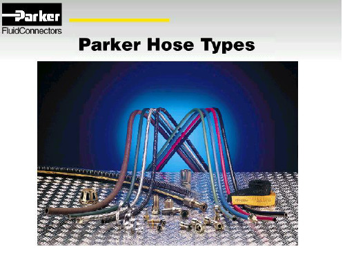
Parker派克软管接头
Parker派克软管接头万星耀科技(深圳)有限公司成立于2009年3月,是世界500强企业Parker Hannifin的国内重要分销商,主要代理Parker 的液压元件、液压成套、流体连接件、密封件以及过滤设备等自动化和过程控制产品,且拥有丰富的液压系统测试、调试和加工能力。
我们提供的服务∙性能可靠、种类齐全的parker流体传动产品∙完善、安心的售后与现场服务∙优质、专业的技术咨询服务Parker派克43系列软管接头,适合于Parkrimp扣压设备家族。
它成本低廉、效率高效,属于永久扣压型接头,并能简单快速地加工成软管总成。
该接头系列完美匹配于派克不剥胶软管,大大地方便了总成的加工操作,并节省了总成的装配时间。
43系列接头表面采用无六价铬处理,适用于各种耐高温,耐低温、工业液压标准、恒压、磷酸酯,吸油和回油软管. 43系列软管接头尺寸范围从¼” 到2“,有多种终端连接形式可选.特征/特点:• 易于插管• 英制螺母• 不锈钢接头可供• 各种终端连接形式可选• 一件式,减少总成加工的复杂性和泄漏点• 不剥胶技术确保总成加工的便利、高效和安全应用:• 石油基液压油和润滑油• 磷酸酯液压油适用软管:301LT、302、304、351TC, 351ST、422、424、426、431、436、451TC, 451ST、471TC, 471ST、472TC、482TC, 482ST、722ST、881公司秉承“以人为本,以德治业,诚信守用,互惠双赢”的经营理念,坚持“以客户为中心,以市场为向导,以质量求发展,以服务求市场”的经营方针,用性能可靠的优质产品,专业的工程技术,优秀的销售团队,完善的售后服务,坚持实施品牌战略和客户满意工程,在行业内外树立了良好的信誉。
详情可查:。
派克焊接接头公制对照表
派克焊接接头公制对照表派克焊接接头是一种常用的焊接接头,在日常生活中,我们也经常会见到它的身影。
派克焊接接头广泛应用于电工,管道,照明和专业音响系统。
它们强度极高,可以抵御强力拉力,是传输电流和气体的理想选择。
派克焊接接头是一种外部零件,由垫圈、链接螺栓、衬垫以及外部螺纹连接而成,可以让电线,管道和设备相互连接。
焊接接头可以大大减少安装过程中的行程时间和安装空间,是一种更便捷的连接方式。
焊接接头主要由规格不同的外部螺纹,衬垫,罩子和三重密封组成,在不同的工作环境中运行性能优异。
派克焊接接头的公制尺寸主要有PG7,PG11,PG13.5,PG16,PG21,PG29等。
PG7的外径是7mm,内管孔的直径是5mm,外壳尺寸为21.4mm;PG11的外径是11mm,内管孔的直径是9mm,外壳尺寸为27.1mm;PG13.5的外径是13.5mm,内管孔的直径是11mm,外壳尺寸为30.1mm;PG16的外径是16mm,内管孔的直径是14mm,外壳尺寸为33.7mm;PG21的外径是21mm,内管孔的直径是19mm,外壳尺寸为41.2mm;PG29的外径是29mm,内管孔的直径是25mm,外壳尺寸为54.8mm。
派克焊接接头的优点很多,比如高质量、高强度、良好的隔离性能和防爆性能,而且它是单一构件,可以提高整体支架的强度。
另外,派克焊接接头的连接方式简单、安装快捷,灵活应用于不同的电机操作现场,这些优点使得它用于各种曲线和折线地设计非常方便。
总之,派克焊接接头是一种可靠的连接方式,在高强度的作业情况下,具有很高的可靠性和耐用性。
由于其公制尺寸的多样性,使派克焊接接头在各种曲线和折线地设计中灵活运用,成为工作之佳伴。
parker液压管接头标准

parker液压管接头标准
Parker液压管接头标准通常由Parker公司制定,以适应其液压系统的需求。
这些标准包括管接头的尺寸、材料、压力等级和连接方式等方面。
以下是Parker液压管接头标准的一些关键方面:
1.尺寸:Parker液压管接头的尺寸通常是根据液压系统的需求进行设计
的。
根据不同的应用场景,管接头的尺寸也会有所不同。
2.材料:Parker液压管接头的材料通常为金属或塑料。
金属管接头具有更
高的强度和耐压性能,而塑料管接头则更轻便和易于安装。
3.压力等级:Parker液压管接头的压力等级是根据系统的需求进行设计
的。
不同的压力等级意味着管接头能够承受不同的液压压力。
4.连接方式:Parker液压管接头的连接方式有多种,包括螺纹连接、卡套
连接、法兰连接等。
根据不同的应用场景和需求,会选择不同的连接方
式。
总之,Parker液压管接头标准是针对其液压系统的特定需求而制定的,以确保液压系统的正常运行和安全性。
在选择和使用Parker液压管接头时,应遵循相关的标准和技术要求。
PARKER接头O型圈型号
系列
软管 外连 接尺寸
订货型号
6
8
10
12
L轻系列
15
18
22
28
35
42
6
8
10
12
S重系列
14
16
20
25
30
38
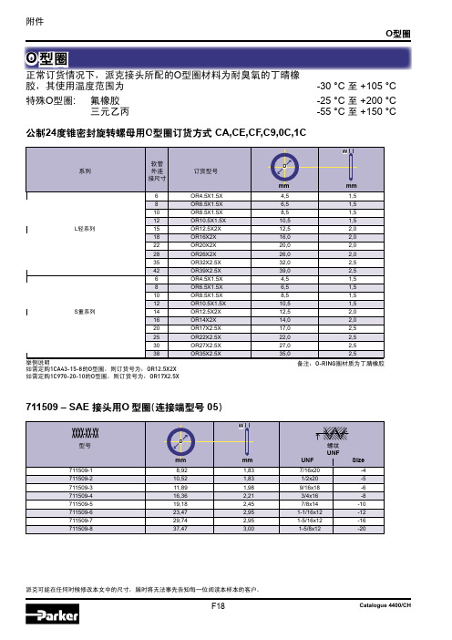
举例说明 如需定购1CA43-15-8的O型圈,则订货号为:OR12.5X2X 如需定购1C970-20-10的O型圈,则订货号为:OR17X2.5X
OR4.5X1.5X OR6.5X1.5X OR8.5X1.5X OR10.5X1.5X OR12.5X2X OR16X2X OR20X2X OR26X2X OR32X2.5X OR39X2.5X OR4.5X1.5X OR6.5X1.5X OR8.5X1.5X OR10.5X1.5X OR12.5X2X OR14X2X OR17X2.5X OR22X2.5X OR27X2.5X OR35X2.5X
mm
mm
Inch
Size
XARG-12 XARG-16 XARG-20 XARG-24
25,4
5,0
3/4
-12
31,9
5,0
1
-16
38,2
5,0
1-1/4
-20
44,7
5,0
1-1/2
-24
派克可能在任何时候修改本文中的尺寸,届时将无法事先告知每一位阅读本样本的客户。
F19
Catalogue 4400/CH
附件
O型圈
O 型圈
正常订货情况下,派克接头所配的O型圈材料为耐臭氧的丁晴橡 胶,其使用温度范围为
特殊O型圈: 氟橡胶 三元乙丙
-30 °C 至 +105 °C
Parker派克A-LOK系列双卡套接头

Parker派克A-LOK系列双卡套接头派克的 A-LOK双卡套接头系列产品能够为仪器仪表,过程控制和分析⾏业等提供稳定的⽆泄漏密封连接。
接头严格按照更⾼质量标准制造,多种尺⼨、耐腐蚀材料和结构可选。
根据⾏业标准,派克的 A-LOK管接头采⽤316不锈钢制造,其它材质如:6Mo合⾦,825合⾦,625合⾦和C-276合⾦可选。
直通接头⽤冷加⼯⼯艺制造,⽽其他特殊形状管件通过细晶粒锻造⼯艺制成。
该管接头适⽤于不同规格的钢管,英制管外径从1/16” 到 2” ,公制管外径从2mm到25mm。
Parker A-LOK two ferrule compression tube fittings are designed to provide reliable leak-free connections for instrumentation, process and control, and analyzer applications that specify a two ferrule system. Manufactured to the highest quality standards, these tube fittings are available in a broad range of sizes, corrosion resistant materials and configurations.As standard, Parker A-LOK tube fitting are manufactured from heat code traceable 316 stainless steel. Other materials include 6Mo, Alloy 825, Alloy 625 and Alloy C-276. Straight fittings are machined from cold finished bar stock, while shaped bodies are machined from close grain forgings.The fittings are available for imperial pipe sizes from 1/16” through to 2” O.D., and for metric sizes from 2 mm through to 25 mm O.D.市场:- 半导体/微电⼦- 化⼯- ⽯化- 电⼒- 核能- 油⽓- 科研机构特征和优势:- 拥有⼴泛的可选结构;卡套管-外螺纹接头卡套管-内螺纹接头联合接头卡套转换接头37扩⼝ (AN) 与 A-LOK 转换接头O型圈密封管接头卡套管转焊接接头⾊谱分析⽤接头软管接头- 采⽤ Suparcase™ 表⾯硬化处理⼯艺- 硬化处理后的卡套能够提供⽆泄漏连接- 螺母内壁经镀银处理,减少螺纹咬死现象发⽣应⽤:- 蒸汽管线- 海上井⼝控⾯板- 传感线路。
PARKER PQT接头样本
0
STI1144100
STI.1144.100
1
STI2144100
STI.2144.100
2
STI0148100
STI.0148.100
0
STI1148100
STI.1148.100
1
STI2148100
STI.2148.100
2
提示 1: 粗体字高亮显示的件号表明该产品为标准产品。 提示 2: 其他件号请联系派克液压过滤部门。
● System20监控器结合内嵌式传感器,能够给客户提供准 确、及时的流量、压力和温度读数,而系统无需停机
● 适用于各种矿物油、水、水/油乳化液 ● 模拟监控器 使用带保护铰接盖的3个Day-Glo刻度表 ● 流量高达380 l/min;双刻度表盘bar/psi & °C/°F. (美制
GPM也可用) ● EM20电子监控器 提供全数字显示 ● 传感器自动校准 ● 可存储300个测试数据 ● 能够实现数据下载保存
刻度表盘详细信息
流量计: 只有规格1和规格2的传感器有双重流量刻度。 量程分别为:100 l/min (26 US GPM)和 380 l/min (100 US GPM). 流量刻度盘还有过载流量指示。
当系统出现逆流或传感器位置对调时,表盘会出现小 于“0”的指示。 压力表: 压力刻度表盘分别有bar和psi指示,压力高达420 bar (6000psi). 温度表: 温度刻度盘读数范围: -10°C ~ +110°C (0°F ~ 230°F). 尺寸: ABS外壳: 292mm (11.5in) ×108mm (4.25in) ×67mm (2.64in) . 重量: 1.4kg (3lbs).
软管定位
派克Parker流体连接件中国区产品手册 上

在线培训
除了传统的课堂培训,派克还提 供在线培训。这些培训包括:
• P-TAC: 派克在线培训和认 证项目可以使您成 为流体连接件产品 的专家。
• 安全学习: 3个20分钟的互动模 块能够帮助员工在进 行相关操作时,学习、理解并且 遵循安全操作的指引
派克培训中心可为您提供系列培 训课程,这些课程均由具有派克 资质认可的培训师授课,并且为 参加学生提供必要学习材料,并 颁发课程证书。
航空航天 环境控制 机电 过滤 流体与气体处理 液压 气动 过程控制 密封与屏蔽
流体连接件中国区产品手册
3400-CN
关于派克汉尼汾
派克汉尼汾是全球领先的运动控制技术及系统的多元化制造商,年销售额超过 100亿美元。我们为商用车辆、行走液压、工业液压和航空航天等行业提供了包 括流体处理、过滤、密封和屏蔽、环境控制、过程控制及航空航天等精准技术 解决方案,我们的产品应用于运动控制领域的各个市场。我们实施多元化、价 值驱动的发展战略,并且很好地定位于全世界每个角落的发展。派克汉尼汾在 美国纽约证券交易所上市代码是“PH”。
ห้องสมุดไป่ตู้
1
Parkrimp扣压设备操作简
单方便:
1. 在软管上标记出插入深 度并插管
2. 选择合适的模具和扣压
环,并将其放置到位
2
3. 将软管和接头放置到
位,按下油泵开关直至扣
压环底端紧靠支架平台。
完成后,打开阀门,将扣
好的总成取出
3
派克青岛工厂可生产多种编织管和缠绕管, 这些软管与派克Parkrimp扣压设备相配套, 为客户提供更经济、更可靠的软管总成。
在派克,我们相信,最好的软管,就是能确保您的工作正确 并正常进行的那个。因此,我们为您提供了全系列可供不同 应用的软管。
parker EO2卡套式管接头的装配[教学]
![parker EO2卡套式管接头的装配[教学]](https://img.taocdn.com/s3/m/de42ae64e3bd960590c69ec3d5bbfd0a7956d5a9.png)
案例三
要点一
总结词
要求高,需保证水质纯净
要点二
详细描述
某水处理厂在装配parker eo2卡套式管接头时,由于对水 质要求极高,需要保证管路系统的密封性和纯净度。首先 ,要选择优质的材料和管接头,确保管路系统的耐腐蚀性 和长期稳定性。其次,在装配过程中要严格控制环境和操 作卫生,避免杂质和污染物进入管路系统。最后,要定期 对管路系统进行清洗和消毒,确保水质的纯净度和安全性 。
案例二
总结词
高风险,需严格遵守安全规程
详细描述
某化工厂在装配parker eo2卡套式管接头时,由于涉 及易燃易爆和有毒介质,需要严格遵守安全规程。首 先,要选择符合安全标准的管接头和管路材料,确保 管路系统的可靠性和安全性。其次,在装配过程中要 遵循安全操作规程,穿戴防护用品,避免直接接触有 毒或腐蚀性介质。最后,要定期对管路系统进行检查 和维护,确保管接头的密封性能和安全性能。
检查卡套式管接头的安装情况,确保其紧固且无松动现 象。
检查卡套式管接头的旋转和移动部分,确保其顺畅无阻。
清洁与润滑
01
使用适当的清洁剂和润 滑剂,保持卡套式管接 头的清洁和润滑。
02
03
04
定期清洁卡套式管接头 的内部和外部,去除灰 尘和污垢。
在适当的位置加注润滑 剂,以减少摩擦和磨损。
注意润滑剂的选择和使 用量,避免过多或过少。
操作要点
在装配之前,应检查管接头和管道是否清洁干燥, 确保没有杂质和水分。
按照正确的顺序安装密封圈和卡套,确保卡套的 开口与密封圈的位置对应。
在装配过程中,应使用专用的卡套工具,按照规 定的力矩值拧紧管接头,确保密封效果良好。
常见问题及解决方案
parker接头

parker接头:为流体传输提供更可靠的连接方式在液压和气动领域,流体传输连接件的重要性毫不言而喻。
为了确保传输的可靠性和稳定性,连接件的选用和设计必须得到高度重视。
Parker Hannifin是一家全球领先的流体传输技术公司,其接头产品在行业内占据重要地位。
本篇文章将对进行介绍和分析,以便更深入地了解这种连接方式,以及其在相关领域的优良表现。
概述是一种高质量的金属管接头产品,可用于液压和气动系统。
它通过将金属管子连接在一起,来传输流体。
这种连接方式比其他连接方式更可靠和耐用。
采用耐高温,耐磨损和耐腐蚀的材料制成,例如不锈钢、铜和铝。
这些优质材料确保了具有长寿命和强度,而且不会因系统内高压或高温而出现故障。
的一大优势是,它可以在高压和高温的情况下保持稳定的连接,从而确保了系统的安全性和稳定性。
此外,Parker提供一系列的接头产品类型,可以满足各种需求。
产品类型Parker Hannifin提供几种不同类型的接头产品,以满足液压和气动系统的不同需求。
以下是主要产品类型的基本介绍:1.管帽接头管帽接头是一种金属管接头,可以让两根金属管子连在一起。
这种接头产品非常适合于连接相对移动的管子。
管帽接头不仅在液压和气动系统中运用广泛,而且在车辆制造、工业生产和石油化工等行业中也有广泛的应用。
2.嵌入式接头嵌入式接头是一种金属接头,适用于安装在液压和气动系统的管子中。
这种接头可以方便地安装在管道内部,从而在系统内部占用空间较少。
嵌入式接头可用于连接不同直径和形状的管子,以适应不同的应用场合。
3.弯头接头弯头接头是一种可以弯曲的金属接头。
这种接头可用于连接两根金属管子并让它们沿着不同的角度弯曲,从而适应各种弯曲和紧凑的空间。
弯头接头也是一种常用的连接方式,能够满足庞大和复杂的液压系统的需求。
4.插入式连接器插入式接头是一种具有高度可靠性和紧凑性的接头方式,它通常用于连接小直径的金属管子和软管。
插入式接头通常采用环状密封设计,以确保连接点的稳定性和密封性。
PARKER派克接头基础教程

气动元件论坛接头基础知识接头基础知识•什么是接头? 其功能是什么?•接头解析•螺纹型式•接头密封型式什么是接头?其功能是什么?使用接头的目的:各种流体动力元件间的液压或气压管路的连接需要各种类型的接头。
把管联接到液压系统上. 接头提供防渗漏密封和系统的接口接头解析油口端&管末端:接头是一种连接流体动力系统元件的连接件,所有的接头除了堵头、堵帽之外,都至少有两个端口。
接头解析油口端&管末端连接到系统元件例:阀、气缸的接头末端称为油口端。
连接到软管、硬管的接头末端称为管末端。
P=油口端T=管末端接头形状直接头接头形状弯接头:有多种角度,但通常为45度或90度接头形状T型接头(三通)接头形状其他接头解析接头螺纹*螺纹是接头的重要部分*提供机械支持力和密封接头螺纹-特征牙顶和牙底:接头螺纹-特征牙侧和牙型角:接头螺纹-特征牙形角和锥度:螺纹角度锥度接头螺纹-特征螺距:螺纹之间的距离接头螺纹-特征公制螺纹常用接头公制螺纹螺距:1.0mm、1.5mm、2.0mm接头螺纹-特征英制螺纹:1英寸牙数(TPI)常用接头英制螺纹螺距:11、14、18、20接头螺纹-尺寸OD:螺纹大径:螺纹外径(牙顶-牙顶)接头螺纹-命名•螺纹的命名系统是个严密的逻辑系统,描述了螺纹尺寸、螺距和型式•英制螺纹:尺寸-牙距-型式例: 螺纹尺寸=-12(3/4“),螺距=20TPI,型式是UNF 螺纹命名: 3/4-20 UNF尺寸螺距型式12 20 UNF常用英制螺纹型式:NPT、NPTF、UN、UNF、BSPT、BSPP接头螺纹-命名•公制螺纹:公制-螺纹尺寸-螺距例: 螺纹尺寸=12,螺距=1.5mm 螺纹命名: M12*1.5公制尺寸螺距M 12 1.5接头螺纹平行螺纹(直螺纹):每个螺纹的外径都相等平行接头螺纹平行螺纹:•平行螺纹只能提供机械支持力•通过其他方式来完成密封例如: O-ring接头螺纹锥形螺纹:螺纹的外径逐渐变小锥形接头螺纹锥形螺纹:•锥形螺纹有2方面作用:z机械支持力z密封 (通常需要其他辅助密封剂)螺纹型式•英制螺纹•公制螺纹英制螺纹管螺纹:管螺纹有锥形螺纹的特征可提供机械支撑力和密封,通常还需使用密封剂防止泄漏。
派克扩口式管接头样本Parker JIC Fitting

Triple-Lok®The universal37° fl ared fi ttingTriple-Lok®Visual indexTube to tubeBulkhead unionTube tomale NPTFTube tomale BSPTTube tomale BSPPTube to straightthread UNFTube tomale metricISO 6149-3Tube tomale metricDIN 3852-1Tube tofemale NPTFHMTX EMTX JMTX KTXp. K9 p. K10 p. K11 p. K14WMTX WEMTX WNTX WJTX WJJTX WLNMp.K15 p.K16 p.K17 p.K18 p.K19 p.K92FMTX CMTXC CTX CCCTX VMTX RMTX SMTXp.K36 p.K51 p.K52 p.K53 p.K59 p.K71 p.K65F3MX C3MX V3MX R3MX S3MXp.K37 p.K54 p.K60 p.K72 p.K66F4OMX F42EDMX C4OMX V4OMX R4OMX S4OMXp.K33 p.K32 p.K49 p.K57 p.K69 p.K63F5OMX FF5OMX C5OMX CC5OX V5OMX R5OMX S5OMX p.K29 p.K31 p.K47 p.K48 p.K56 p.K68 p.K62F87OMX C87OMX V87OMX R87OMX S87OMXp.K28 p.K46 p.K55 p.K67 p.K61F8OMX F82EDMX C8OMX V8OMX R8OMX S8OMXp.K35 p.K34 p.K50 p.K58 p.K70 p.K64GMTX WGMTX DMTX OTX MTX G6Xp.K74 p.K75 p.K76 p.K77 p.K78 p.K79KTriple-Lok ®Triple-Lok®KTriple-Lok ®BTX NutTriple-Lok ® 37° Flare end nut SAE 070110 MS51531Tube Thread Weight O.D. UN/UNF-2B C D L (steel) Triple-Lok ® Triple-Lok ® Triple-Lok ® mm in. T6 in. mm mm g/1 piece Steel Stainless Steel Brass 1/8 5/16-24 3/8 5 14 6 2 BTX-S 2 BTX-SS2 BTX-B 3/16 3/8-24 7/16 6 16 83 BTX-S 3 BTX-SS 3 BTX-B 6 1/4 7/16-20 9/16 8 16 11 4 BTX-S 4 BTX-SS 4 BTX-B 8 5/16 1/2-20 5/8 10 17 145 BTX-S 5 BTX-SS 5 BTX-B 10 3/8 9/16-18 11/16 11 18 18 6 BTX-S 6 BTX-SS 6 BTX-B 12 1/2 3/4-16 7/8 15 22 29 8 BTX-S 8 BTX-SS 8 BTX-B 14, 15, 16 5/8 7/8-14 1 18 25 54 10 BTX-S 10 BTX-SS 10 BTX-B 18, 20 3/4 1 1/16-12 1 1/4 21 26 73 12 BTX-S 12 BTX-SS 12 BTX-B 22 7/8 1 3/16-12 1 3/8 24 28 100 14 BTX-S 14 BTX-SS 14 BTX-B 25 1 1 5/16-12 1 1/2 28 29 104 16 BTX-S 16 BTX-SS 16 BTX-B 28, 30, 32 1 1/4 1 5/8-12 2 34 31 240 20 BTX-S 20 BTX-SS 20 BTX-B 35, 38 1 1/2 1 7/8-12 2 1/4 41 36 325 24 BTX-S 24 BTX-SS 24 BTX-B2 2 1/2-12 2 7/8 55 45 549 32 BTX-S32 BTX-SSOrder codes shown are part of our current manufacturing programme.Triple-Lok®BMTX NutTriple-Lok® 37° Flare end nutSAE 070110Tube Thread WeightO.D. UN/UNF-2B C D L (steel) Triple-Lok® Triple-Lok®Steelpiece Steel Stainless mm in. T6 mm mm mm g/16 1/4 7/16-20 14 8 16 11 4BMTXS 4BMTXSS8 5/16 1/2-20 17 10 17 14 5BMTXS 5BMTXSS10 3/8 9/16-18 19 11 18 18 6BMTXS 6BMTXSS12 1/2 3/4-16 22 15 21 29 8BMTXS 8BMTXSS14, 15, 16 5/8 7/8-14 27 18 25 42 10BMTXS 10BMTXSS 18, 20 3/4 1 1/16-12 32 22 26 73 12BMTXS 12BMTXSS5/16-12 41 28 28 104 16BMTXS 16BMTXSS25 1 128, 30, 32 1 1/4 1 5/8-12 50 34 31 240 20BMTXS 20BMTXSS 35, 38 1 1/2 1 7/8-12 60 41 36 325 24BMTXS 24BMTXSS42 21/4 65 48 40 437 28BMTXS 28BMTXSSOrder codes shown are part of our current manufacturing programme.KTriple-Lok ®Tube WeightO.D. L X (steel) Triple-Lok ® Triple-Lok ® Triple-Lok ®mm mm mm g/1 piece Steel Stainless Steel Brass 6 10 10 2 TXS6 TXSS6 TXB6 8 11 11 2 TXS8 TXSS8 TXB8 10 13 13 2 TXS10 TXSS10 TXB10 12 14 17 7 TXS12 TXSS12 TXB12 14 17 20 13 TXS14 TXSS14 TXB14 15 17 20 10 TXS15 TXSS15 TXB15 16 17 20 7 TXS16 TXSS16 TXB16 18 17 25 16 TXS18 TXSS18 TXB18 20 17 25 12 TXS20 TXSS20 TXB20 22 19 28 25 TXS22 TXSS22 TXB22 25 20 31 21 TXS25 TXSS25 TXB25 28 23 39 40 TXS28 TXSS28 TXB28 30 23 39 45 TXS30 TXSS30 TXB30 32 23 39 30 TXS32 TXSS32 TXB32 35 28 45 60 TXS35 TXSS35 TXB35 38 28 45 51 TXS38 TXSS38 TXB38 422955149TXS42 TXSS42 TXB42Order codes shown are part of our current manufacturing programme.TX SleeveTriple-Lok ® 37° Flare tube end sleeve for metric tubes SAE 070105Triple-Lok ®Tube WeightO.D. L X (steel) T riple-Lok ® Triple-Lok ® Triple-Lok ® in. mm mm g/1 piece Steel Stainless Steel Brass 1/8 9 7 22 TX-S 2 TX-SS 2 TX-B 3/169823 TX-S 3 TX-SS 3 TX-B 1/4 10 10 2 4 TX-S 4 TX-SS 4 TX-B 5/16 11 11 25 TX-S 5 TX-SS 5 TX-B 3/8 13 13 36 TX-S 6 TX-SS 6 TX-B 1/2 14 17 68 TX-S 8 TX-SS 8 TX-B 5/8 17 20 8 10 TX-S 10 TX-SS 10 TX-B 3/4 17 25 13 12 TX-S 12 TX-SS 12 TX-B 7/8 19 28 18 14 TX-S 14 TX-SS 14 TX-B 1 20 31 23 16 TX-S 16 TX-SS 16 TX-B 1 1/4 23 39 30 20 TX-S 20 TX-SS 20 TX-B 1 1/2 28 45 51 24 TX-S 24 TX-SS 24 TX-B 2306115632 TX-S32 TX-SS32 TX-BOrder codes shown are part of our current manufacturing programme.TX SleeveTriple-Lok ® 37° Flare tube sleeve SAE 070105 MS51533KTriple-Lok ®Tube 1 Tube 2 Thread Thread Weight PN (bar)O.D. O.D. UN/UNF-2A UN/UNF-2A C D D1 L1 (steel) Triple-Lok ® Triple-Lok ® Triple-Lok ®mm in. mm in. T1 T2 mm mm mm mm g/1 piece Steel Stainless Steel Brass S SS1/8 1/8 5/16-24 5/16-24 11 2 2 30 9 2 HTX-S 500 —3/16 3/16 3/8-24 3/8-24 11 3 3 31 10 3 HTX-S 500 — 6 1/4 6 1/4 7/16-20 7/16-20 13 4 4 35 16 4HMTXS 4HMTXSS 4HMTXB 500 350 6 1/4 1/8 7/16-20 5/16-24 13 5 2 32 12 4-2 HTX-S 4-2HMTXSS 4-2HMTXB 500 350 6 1/4 3/16 7/16-20 3/8-24 13 5 3 33 14 4-3 HTX-S 4-3HMTXSS 4-3HMTXB 500 350 8 5/16 8 5/16 1/2-20 1/2-20 14 6 6 35 18 5HMTXS 5HMTXSS 5HMTXB 420 350 8 5/16 6 1/4 1/2-20 7/16-20 14 6 5 35 18 5-4 HTX-S 5-4HMTXSS 5-4HMTXB 420 350 10 3/8 10 3/8 9/16-18 9/16-18 17 8 8 36 25 6HMTXS 6HMTXSS 6HMTXB 420 350 10 3/8 6 1/4 9/16-18 7/16-20 17 8 4 36 22 6-4HMTXS 6-4HMTXSS 6-4HMTXB 420 350 10 3/8 8 5/16 9/16-18 1/2-20 17 8 6 36 25 6-5 HTX-S 6-5HMTXSS 6-5HMTXB 420 350 12 1/2 12 1/2 3/4-16 3/4-16 19 10 10 41 52 8HMTXS 8HMTXSS 8HMTXB 420 350 12 1/2 6 1/4 3/4-16 7/16-20 21 10 5 39 45 8-4 HTX-S 8-4HMTXSS 8-4HMTXB 420 350 12 1/2 10 3/8 3/4-16 9/16-18 19 10 8 39 45 8-6HMTXS 8-6HMTXSS 8-6HMTXB 420 350 14, 15,16 5/8 14, 15,16 5/8 7/8-14 7/8-14 24 12 12 48 80 10HMTXS 10HMTXSS 10HMTXB 350 350 14, 15,16 5/8 10 3/8 7/8-14 9/16-18 24 13 8 43 60 10-6HMTXS 10-6HMTXSS 10-6HMTXB 350 350 14, 15,16 5/8 12 1/2 7/8-14 3/4-16 24 12 10 45 68 10-8HMTXS 10-8HMTXSS 10-8HMTXB 350 350 18, 20 3/4 18, 20 3/4 1 1/16-12 1 1/16-12 27 16 16 55 125 12HMTXS 12HMTXSS 12HMTXB 350 350 18, 20 3/4 12 1/2 1 1/16-12 3/4-16 29 16 10 50 101 12-8 HTX-S 12-8HMTXSS 12-8HMTXB 350 350 20 3/4 14, 15,16 5/8 1 1/16-12 7/8-14 29 16 12 52 113 12-10HMTXS 12-10HMTXSS 12-10HMTXB 350 350 22 7/8 22 7/8 1 3/16-12 1 3/16-12 32 18 18 56 156 14 HTX-S 14HMTXSS 14HMTXB 280 280 25 1 25 1 1 5/16-12 1 5/16-12 36 22 22 57 131 16HMTXS 16HMTXSS 16HMTXB 280 280 25 1 20 3/4 1 5/16-12 1 1/16-12 36 22 16 56 169 16-12HMTXS 16-12HMTXSS 16-12HMTXB 280 280 28, 30, 32 1 1/4 28, 30, 32 1 1/4 1 5/8-12 1 5/8-12 46 28 28 62 271 20HMTXS 20HMTXSS 20HMTXB 280 210 28, 30, 32 1 1/4 25 1 1 5/8-12 1 5/16-12 46 28 22 61 235 20-16HMTXS 20-16HMTXSS 20-16HMTXB 280 210 35, 38 1 1/2 35, 38 1 1/2 1 7/8-12 1 7/8-12 50 33 33 70 382 24HMTXS 24HMTXSS 24HMTXB 210 210 42 42 2 1/4-12 2 1/4-12 60 39 39 71 469 28HMTXS 28HMTXSS 28HMTXB 140 150 2 2 2 1/2-12 2 1/2-12 67 45 45 87 785 32 HTX-S 32HMTXSS 32HMTXB 140 150Order codes shown are part of our current manufacturing programme.Imperial and metric parts may vary in hexagon dimensions.PN (bar)= PN (MPa)10Pressure ratings – PN shown, apply to Steel and Stainless Steel versions of the product.For Brass parts reduce pressures by 35%.HMTX UnionTriple-Lok ® 37° Flare ends SAE 070101 MS51501Triple-Lok®EMTX Union elbowTriple-Lok® 37° Flare endsSAE 070201 MS51505(bar) Tube Thread Thread Weight PNY(steel)Triple-Lok® Triple-Lok® Triple-Lok®M1MUN/UNF2-ADD1O.D. UN/UNF-2Amm in. T T1 mm in. mm mm mm g/1 piece Steel Stainless Steel Brass S SS 1/8 5/16-24 5/16-24 2 2 20 20 11 18 2 ETX-S 500—— 3/16 3/8-24 3/8-24 3 3 21 21 11 20 3 ETX-S 500500 3506 1/4 7/16-20 7/16-20 4 4 23 23 11 25 4EMTXS 4EMTXSS 4ETX-B420 350ETX-B8 5/16 1/2-20 1/2-20 6 6 24 24 13 32 5EMTXS 5EMTXSS 5420 35010 3/8 9/16-18 9/16-18 8 8 27 27 14 44 6EMTXS 6EMTXSS 6ETX-B10 3/8 9/16-18 7/16-20 8 4 27 27 14 40 6-4 ETX-S 6-4EMTXSS 6-4 ETX-B 420 350420 350ETX-B12 1/2 3/4-16 3/4-16 10 10 32 32 19 88 8EMTXS 8EMTXSS 812 1/2 3/4-16 3/8-24 10 8 32 29 19 75 8-6 ETX-S 8-6EMTXSS 420 —350 350ETX-B 15,16 5/8 7/8-14 7/8-14 12 12 37 37 22 139 10EMTXS 10EMTXSS 1014,15,16 5/8 7/8-14 3/4-16 12 10 37 34 22 120 10-8 ETX-S 10-8EMTXSS 10-8 ETX-B 350 35014,ETX-B350 3501/16-12 16 16 42 42 27 258 12EMTXS 12EMTXSS 121/16-12 118,20 3/4 11/16-12 3/4-16 16 10 42 46 27 220 12-8 ETX-S 12-8EMTXSS 350 —20 3/4 118,1/16-12 7/8-14 16 12 42 39 27 240 12-10 ETX-S 12-10EMTXSS 350 —20 3/4 118,3/16-12 18 18 44 44 30 273 14 ETX-S 14EMTXSS 280 —22 7/8 13/16-12 1ETX-B280 2805/16-12 22 22 46 46 33 333 16EMTXS 16EMTXSS 165/16-12 125 1 122,5/16-12 11/16-12 22 16 46 45 33 310 16-12 ETX-S 16-12EMTXSS 16-12 ETX-B 280 28025 1 122,ETX-B280 21028, 30, 32 1 1/4 1 5/8-12 1 5/8-12 28 28 52 52 41 586 20EMTXS 20EMTXSS 20210 140ETX-B 35, 38 1 1/2 1 7/8-12 1 7/8-12 33 33 59 59 48 778 24EMTXS 24EMTXSS 24—1/4-12 21/4-12 39 39 74 74 63 1100 28 ETX-S 140 3/4 242 1—1/2-12 45 45 78 78 64 1680 32 ETX-S 1402 21/2-12 2Order codes shown are part of our current manufacturing programme.Imperial and metric parts may vary in hexagon dimensions.PN (bar)= PN (MPa)10Pressure ratings – PN shown, apply to Steel and Stainless Steel versions of the product.For Brass parts reduce pressures by 35%.KKKTX Union crossTriple-Lok® 37° Flare end (four ends)SAE 070501 MS51517Tube Thread Weight PN(bar)Triple-Lok® Triple-Lok® Triple-Lok®(steel)O.D. UN/UNF-2AD M YSSSteel Brass Spiece Steel Stainless mm in. T mm mm mm g/11/4 7/16-20 4 23 11 41 4 KTX-S 4 KTX-SS 4 KTX-B 500 35065/16 1/2-20 6 24 14 50 5 KTX-S 5 KTX-SS 5 KTX-B 420 350810 3/8 9/16-18 8 27 14 68 6 KTX-S 6 KTX-SS 6 KTX-B 420 35012 1/2 3/4-16 10 32 19 144 8 KTX-S 8 KTX-SS 8 KTX-B 420 35014, 15,16 5/8 7/8-14 12 37 22 220 10 KTX-S 10 KTX-SS 10 KTX-B 350 350 18, 20 3/4 1 1/16-12 16 42 27 345 12 KTX-S 12 KTX-SS 12 KTX-B 350 350 5/16-12 22 46 33 588 16 KTX-S 16 KTX-SS 16 KTX-B 280 28025 1 1Order codes shown are part of our current manufacturing programme.Imperial and metric parts may vary in hexagon dimensions.PN (bar)= PN (MPa)10Pressure ratings – PN shown, apply to Steel and Stainless Steel versions of the product.For Brass parts reduce pressures by 35%.KMaximum bulkhead wallthicknessTube O.D. Straight bulkhead unionShape bulkhead unionMax. thicknessMax. thicknessSize inch metric mmmm4 1/4 6 8.4 5.35 5/16 8 8.4 5.3 6 3/8 10 10.7 7.18 1/2 12 11.2 8.4 10 5/8 14–16 10.9 8.1 12 3/4 18–2011.2 8.6 14 7/8 10.4 7.9 16 1 22–25 9.9 7.4 20 1 1/4 28–32 10.2 7.4 24 1 1/235–387.1 — 3227.1—WMTX Bulkhead unionTriple-Lok ® 37° Flare ends SAE 070601 MS51520Tube Thread WeightPN (bar) O.D. UN/UNF-2A C2 D I1 L4 (steel) Triple-Lok ® Triple-Lok ® Triple-Lok ®mm in. T mm mm mm mm g/1 piece Steel Stainless Steel BrassS SS6 1/4 7/16-20 17 4 31 53 41 4WMTXWLNMS 4WMTXWLNMSS 4WMTXWLNMB 500 3508 5/16 1/2-20 19 6 31 53 49 5WMTXWLNMS 5WMTXWLNMSS 5WMTXWLNMB 420 350 10 3/8 9/16-18 22 8 33 55 64 6WMTXWLNMS 6WMTXWLNMSS 6WMTXWLNMB 420 350 12 1/2 3/4-16 24 10 37 62 111 8WMTXWLNMS 8WMTXWLNMSS 8WMTXWLNMB 420 350 14, 15,16 5/8 7/8-14 30 12 40 70 157 10WMTXWLNMS 10WMTXWLNMSS 10WMTXWLNMB 350 350 18, 20 3/4 1 1/16-12 36 16 44 79 254 12WMTXWLNMS 12WMTXWLNMSS 12WMTXWLNMB 350 350 22 7/8 1 3/16-12 38 18 45 80 296 14 WTX-WLN-S 14WMTXWLNMSS 14WMTXWLNMB 280 280 25 1 1 5/16-12 41 22 44 80 337 16WMTXWLNMS 16WMTXWLNMSS 16WMTXWLNMB 280 280 28, 30, 32 1 1/4 1 5/8-12 50 28 46 84 462 20WMTXWLNMS 20WMTXWLNMSS 20WMTXWLNMB 280 210 35, 38 1 1/2 1 7/8-12 55 33 46 89 695 24WMTXWLNMS 24WMTXWLNMSS 24WMTXWLNMB 210 140Order codes shown are part of our current manufacturing programme. Imperial and metric parts may vary in hexagon dimensions.For the version without the locknut remove “WLNM” (e. g. 16WMTX)PN (bar)= PN (MPa)10Pressure ratings – PN shown, apply to Steel and Stainless Steel versions of the product.For Brass parts reduce pressures by 35%.WEMTX Bulkhead union elbowTriple-Lok® 37° Flare endsSAE 070701 MS51507(bar) Tube Thread Weight PNM4YM3(steel) Triple-Lok® Triple-Lok® Triple-Lok®I2C2O.D. UN/UNF-2ADmm in. T mm mm mm mm mm mm g/1 piece Steel Stainless Steel Brass S SS6 1/4 7/16-20 17 4 26 25 40 11 44 4 WETX-WLN-S 4 WETX-WLN-SS 4 WETX-WLN-B 500 3508 5/16 1/2-20 19 6 26 27 44 13 59 5 WETX-WLN-S 5 WETX-WLN-SS 5 WETX-WLN-B 420 35010 3/8 9/16-18 22 8 28 28 46 14 72 6WEMTXWLNMS 6 WETX-WLN-SS 6 WETX-WLN-B 420 35012 1/2 3/4-16 24 10 32 36 54 19 145 8WEMTXWLNMS 8 WETX-WLN-SS 8 WETX-WLN-B 420 350 14,15,16 5/8 7/8-14 30 12 35 40 61 22 212 10WEMTXWLNMS 10 WETX-WLN-SS 10 WETX-WLN-B 350 350 1/16-12 36 16 40 45 68 27 345 12WEMTXWLNMS 12 WETX-WLN-SS 12 WETX-WLN-B 350 35020 3/4 118,3/16-12 38 18 40 49 71 33 370 14 WETX-WLN-S 14 WETX-WLN-SS 280 —22 7/8 15/16-12 41 22 40 49 71 33 474 16 WETX-WLN-S 16 WETX-WLN-SS 280 —25 1 128, 30, 32 1 1/4 1 5/8-12 48 28 41 55 80 41 753 20 WETX-WLN-S 20 WETX-WLN-SS 280 —Order codes shown are part of our current manufacturing programme.Imperial and metric parts may vary in hexagon dimensions.For the version without the locknut remove “WLNM” (e. g. 16WETX)PN (bar)= PN (MPa)10Pressure ratings – PN shown, apply to Steel and Stainless Steel versions of the product.For Brass parts reduce pressures by 35%.Maximum bulkhead wallthicknessTube O.D. Straight bulkhead union Shape bulkhead unionMax. thickness Max. thicknessSize inch metric mm mm4 1/4 6 8.4 5.35 5/16 8 8.4 5.36 3/8 10 10.7 7.18 1/2 12 11.2 8.410 5/8 14–16 10.9 8.112 3/4 18–20 11.2 8.614 7/8 10.4 7.916 1 22–25 9.9 7.41/4 28–32 10.2 7.420 11/2 35–38 7.1 —24 132 2 7.1 —KMaximum bulkhead wallthicknessTube O.D. Straight bulkhead unionShape bulkhead unionMax. thicknessMax. thicknessSize inch metric mmmm4 1/4 6 8.4 5.35 5/16 8 8.4 5.3 6 3/8 10 10.7 7.18 1/2 12 11.2 8.4 10 5/8 14–16 10.9 8.1 12 3/4 18–2011.2 8.6 14 7/8 10.4 7.9 16 1 22–25 9.9 7.4 20 1 1/4 28–32 10.2 7.4 24 1 1/235–387.1 — 3227.1—WNTX 45° Bulkhead union elbowTriple-Lok ® 37° Flare ends SAE 070801 MS51509Tube Thread WeightPN (bar) O.D. UN/UNF-2A C2 D I2 M2 M9 Y (steel) Triple-Lok ® Triple-Lok ®mm in. T mm mm mm mm mm mm g/1 piece Steel Stainless Steel S SS6 1/4 7/16-20 17 4 26 18 39 11 324 WNTX-WLN-S 4 WNTX-WLN-SS 500 350 8 5/16 1/2-20 19 6 26 20 42 14 415 WNTX-WLN-S 420 —10 3/8 9/16-18 21 8 28 21 42 14 48 6 WNTX-WLN-S 6 WNTX-WLN-SS 420 350 12 1/2 3/4-16 25 10 32 25 49 19 105 8 WNTX-WLN-S 8 WNTX-WLN-SS 420 350 14, 15,16 5/8 7/8-14 29 12 35 28 55 22 152 10 WNTX-WLN-S 10 WNTX-WLN-SS 350 350 18, 20 3/4 1 1/16-12 35 16 40 33 62 27 245 12 WNTX-WLN-S 12 WNTX-WLN-SS 350 350 22, 25 1 1 5/16-12 41 22 40 37 65 33 355 16 WNTX-WLN-S 16 WNTX-WLN-SS 280 28028, 30, 321 1/41 5/8-12 48 28 41 40 67 4146520 WNTX-WLN-S280 —Order codes shown are part of our current manufacturing programme.Imperial and metric parts may vary in hexagon dimensions.For the version without the locknut remove “WLN” (e.g. 16 WNTX)PN (bar)= PN (MPa)10Pressure ratings – PN shown, apply to Steel and Stainless Steel versions of the product.Maximum bulkhead wallthicknessTube O.D. Straight bulkhead unionShape bulkhead unionMax. thicknessMax. thicknessSize inch metric mmmm4 1/4 6 8.4 5.35 5/16 8 8.4 5.3 6 3/8 10 10.7 7.18 1/2 12 11.2 8.4 10 5/8 14–16 10.9 8.1 12 3/4 18–2011.2 8.6 14 7/8 10.4 7.9 16 1 22–25 9.9 7.4 20 1 1/4 28–32 10.2 7.4 24 1 1/235–387.1 — 3227.1—WJTX Bulkhead branch teeTriple-Lok ® 37° Flare ends SAE 070959 MS51515Tube Thread WeightPN (bar) O.D. UN/UNF-2A C2 D I2 M3 M4 Y (steel) Triple-Lok ® Triple-Lok ®mm in. T mm mm mm mm mm mm g/1 piece Steel Stainless Steel S SS6 1/4 7/16-20 17 4 26 25 40 11 454 WJTX-WLN-S 4 WJTX-WLN-SS 500 35010 3/8 9/16-18 21 8 28 28 46 14 71 6 WJTX-WLN-S 6 WJTX-WLN-SS 420 350 12 1/2 3/4-16 25 10 32 35 54 19 158 8 WJTX-WLN-S 8 WJTX-WLN-SS 420 350 14, 15,16 5/8 7/8-14 29 12 35 40 61 22 297 10 WJTX-WLN-S 10 WJTX-WLN-SS 350 350 18, 20 3/4 1 1/16-12 35 16 40 45 68 27 379 12 WJTX-WLN-S 12 WJTX-WLN-SS 350 35022, 25 1 1 5/16-12 42 22 40 49 71 33 420 16 WJTX-WLN-S 280 — 28, 30, 321 1/41 5/8-12 48 28 41 55 79 4150020 WJTX-WLN-S280 —Order codes shown are part of our current manufacturing programme.Imperial and metric parts may vary in hexagon dimensions.For the version without the locknut remove “WLN” (e.g. 16 WJTX)PN (bar)= PN (MPa)10Pressure ratings – PN shown, apply to Steel and Stainless Steel versions of the product.KMaximum bulkhead wallthicknessTube O.D. Straight bulkhead unionShape bulkhead unionMax. thicknessMax. thicknessSize inch metric mmmm4 1/4 6 8.4 5.35 5/16 8 8.4 5.3 6 3/8 10 10.7 7.18 1/2 12 11.2 8.4 10 5/8 14–16 10.9 8.1 12 3/4 18–2011.2 8.6 14 7/8 10.4 7.9 16 1 22–25 9.9 7.4 20 1 1/4 28–32 10.2 7.4 24 1 1/235–387.1 — 3227.1—WJJTX Bulkhead run teeTriple-Lok ® 37° Flare ends SAE 070958 MS51516Tube Thread Weight O.D. UN/UNF-2A C2 D I2 M3 M4 Y (steel) Triple-Lok ® PN mm in. T mm mm mm mm mm mm g/1 piece Steel (bar)6 1/4 7/16-20 17 4 26 25 40 11584 WJJTX-WLN-S 50010 3/8 9/16-18 21 8 28 28 46 14756 WJJTX-WLN-S 420 12 1/2 3/4-16 25 10 32 35 54 19 158 8 WJJTX-WLN-S 420 14, 15,16 5/8 7/8-14 29 12 35 40 61 22 309 10 WJJTX-WLN-S 350 18, 20 3/4 1 1/16-12 35 16 40 45 68 27 340 12 WJJTX-WLN-S 350 22, 25 1 1 5/16-12 42 22 40 49 71 36 390 16 WJJTX-WLN-S 280 28, 30, 32 1 1/4 1 5/8-1248 28 41 55 79 4145020 WJJTX-WLN-S280Order codes shown are part of our current manufacturing programme.Imperial and metric parts may vary in hexagon dimensions.For the version without the locknut remove “WLN” (e.g. 16 WJJTX)PN (bar)= PN (MPa)10Tube Thread Thread Weight PN (bar)O.D. UN/UNF-2A UN/UNF-2B C3 D M M5 M10 Y (steel) Triple-Lok ® Triple-Lok ®mm in. T T6 mm mm mm mm mm mm g/1 piece Steel Stainless Steel S SS 3/16 3/8-24 3/8-24 13 3 21 25 16 11273 C6X-S 500 — 6 1/4 7/16-20 7/16-20 16 4 23 25 17 11 37 4C6MXS 4C6MXSS 500 350 8 5/16 1/2-20 1/2-20 17 6 24 27 17 13 43 5C6MXS 5C6MXSS 420 350 10 3/8 9/16-18 9/16-18 19 8 27 32 22 14 54 6C6MXS 6C6MXSS 350 350 12 1/2 3/4-16 3/4-16 22 10 32 35 24 19 105 8C6MXS 8C6MXSS 350 350 14, 15,16 5/8 7/8-14 7/8-14 27 12 37 41 28 22 162 10C6MXS 10C6MXSS 350 350 18, 20 3/4 1 1/16-12 1 1/16-12 32 16 42 44 30 27 260 12C6MXS 12C6MXSS 350 350 22 7/8 1 3/16-12 1 3/16-12 35 18 46 45 34 33 293 14 C6X-S 250 — 25 1 1 5/16-12 1 5/16-12 38 22 46 51 36 33 420 16C6MXS 16C6MXSS 250 250 28, 30, 32 1 1/4 1 5/8-12 1 5/8-12 50 28 52 59 43 41 679 20 C6X-S 20C6MXSS 250 210 35, 38 1 1/2 1 7/8-12 1 7/8-12 57 33 59 66 47 48 747 24 C6X-S 24C6MXSS 170 140 22 1/2-12 2 1/2-12 73 45 78 89 62 6692032 C6X-S 110 —Order codes shown are part of our current manufacturing programme.Imperial and metric parts may vary in hexagon dimensions.PN (bar)= PN (MPa)10Pressure ratings – PN shown, apply to Steel and Stainless Steel versions of the product.C6MX Swivel nut elbowTriple-Lok ® 37° Flare end / Triple-Lok ® 37° Flare female swivel end SAE 070221 MS51521KTube Thread Thread Weight PN (bar) O.D. UN/UNF-2A UN/UNF-2B C3 D M2 M6 M11 Y (steel) Triple-Lok ® Triple-Lok ®mm in. T T6 mm mm mm mm mm mm g/1 piece Steel Stainless Steel S SS 6 1/4 7/16-20 7/16-20 14 4 18 24 15 11 30 4 V6X-S 4 V6X-SS 500 350 8 5/16 1/2-20 1/2-20 16 6 20 25 16 14 45 5 V6X-S 5 V6X-SS 420 350 10 3/8 9/16-18 9/16-18 19 8 21 28 19 14 47 6 V6X-S 6 V6X-SS 350 350 12 1/2 3/4-16 3/4-16 22 10 25 33 22 19 89 8V6MXS 8 V6X-SS 350 350 14, 15,16 5/8 7/8-14 7/8-14 27 12 28 37 24 22 131 10 V6X-S 10 V6X-SS 350 350 18, 20 3/4 1 1/16-12 1 1/16-12 32 16 33 38 24 27 203 12 V6X-S 12 V6X-SS 350 350 22 7/8 1 3/16-12 1 3/16-12 35 18 35 41 28 30 291 14 V6X-S 250 — 25 1 1 5/16-12 1 5/16-12 38 22 37 44 29 33 335 16 V6X-S 16 V6X-SS 250 250 28, 30, 32 1 1/4 1 5/8-12 1 5/8-12 51 27 40 52 36 41 572 20 V6X-S 20 V6X-SS 250 210 35, 38 1 1/2 1 7/8-12 1 7/8-12 57 33 45 58 39 48 715 24 V6X-S 24 V6X-SS 170 140 2 2 1/2-12 2 1/2-12 72 45 56 70 50 66 960 32 V6X-S 32 V6X-SS 110 110Order codes shown are part of our current manufacturing programme.Imperial and metric parts may vary in hexagon dimensions.PN (bar)= PN (MPa)10Pressure ratings – PN shown, apply to Steel and Stainless Steel versions of the product.V6MX 45° Swivel nut elbowTriple-Lok ® 37° Flare end / Triple-Lok ® 37° Flare female swivel endSAE 070321 MS51522Tube Thread Thread Weight PN (bar)O.D. UN/UNF-2A UN/UNF-2B C3 D M M5 M10 Y (steel) Triple-Lok ® Triple-Lok ®mm in. T T6 mm mm mm mm mm mm g/1 piece Steel Stainless Steel S SS 6 1/47/16-20 7/16-20 16 4 23 25 17 11 44 4 S6X-S 4 S6X-SS 500 350 8 5/161/2-20 1/2-20 17 6 24 27 17 13 58 5S6MXS 5 S6X-SS 420 350 10 3/89/16-18 9/16-18 19 8 27 32 22 14 71 6S6MXS 6 S6X-SS 350 350 12 1/23/4-16 3/4-16 22 10 32 35 24 19 133 8S6MXS 8 S6X-SS 350 350 14, 15,16 5/87/8-14 7/8-14 27 12 37 41 28 22 203 10S6MXS 10 S6X-SS 350 350 18, 20 3/41 1/16-12 1 1/16-12 32 16 42 44 30 27 328 12S6MXS 12 S6X-SS 350 350 25 11 5/16-12 1 5/16-12 38 22 46 51 36 33 483 16S6MXS 16 S6X-SS 250 250 28, 30, 32 1 1/41 5/8-12 1 5/8-12 50 28 52 59 43 41 708 20 S6X-S 20 S6X-SS 250 210 35, 38 1 1/2 1 7/8-12 1 7/8-12 57 33 59 68 49 48 1100 24 S6X-S 24 S6X-SS 170 170Order codes shown are part of our current manufacturing programme.Imperial and metric parts may vary in hexagon dimensions.PN (bar) = PN (MPa)10Pressure ratings – PN shown, apply to Steel and Stainless Steel versions of the product.S6MX Swivel nut branch teeTriple-Lok ® 37° Flare ends / Triple-Lok ® 37° Flare female swivel endSAE 070433 MS51524KTube Thread Thread Weight PN (bar) O.D. UN/UNF-2A UN/UNF-2B C3 D M M5 M10 Y (steel) Triple-Lok ® Triple-Lok ®mm in. T T6 mm mm mm mm mm mm g/1 piece Steel Stainless Steel S SS 6 1/4 7/16-20 7/16-20 16 4 23 25 17 11 44 4 R6X-S 4 R6X-SS 500 350 8 5/16 1/2-20 1/2-20 17 6 24 27 17 13 56 5R6MXS 5 R6X-SS 420 350 10 3/8 9/16-18 9/16-18 19 8 27 32 22 14 69 6R6MXS 6 R6X-SS 350 350 12 1/2 3/4-16 3/4-16 22 10 32 35 24 19 136 8R6MXS 8 R6X-SS 350 350 14, 15,16 5/8 7/8-14 7/8-14 27 12 37 41 28 22 207 10R6MXS 10 R6X-SS 350 350 18, 20 3/4 1 1/16-12 1 1/16-12 32 16 42 44 30 27 319 12R6MXS 12 R6X-SS 350 350 22 7/8 1 3/16-12 1 3/16-12 35 18 46 45 34 33 622 14 R6X-S 14 R6X-SS 250 250 25 1 1 5/16-12 1 5/16-12 38 22 46 51 36 33 489 16R6MXS 16 R6X-SS 250 250 28, 30, 32 1 1/4 1 5/8-12 1 5/8-12 50 28 52 59 43 41 712 20R6MXS 20 R6X-SS 250 210 35, 38 1 1/2 1 7/8-12 1 7/8-12 57 33 59 66 47 48 1100 24 R6X-S 24 R6X-SS 170 170Order codes shown are part of our current manufacturing programme.Imperial and metric parts may vary in hexagon dimensions.PN (bar)= PN (MPa)10Pressure ratings – PN shown, apply to Steel and Stainless Steel versions of the product.R6MX Swivel nut run teeTriple-Lok ® 37° Flare ends / Triple-Lok ® 37° Flare female swivel endSAE 070432KKTubeThread Thread Weight PN (bar) O.D.Metric UN/UNF-2A L D C U (steel) Triple-Lok ® Triple-Lok ® mm in. T87 T mm mm mm mm g/1 piece Steel Stainless Steel S SS 6 1/4 M10 × 1.0 7/16-20 30 14 14 9 25 4M10F87OMXS 4M10F87OMXSS 500 350 8 5/16 M10 × 1.0 1/2-20 30 14 14 9 30 5M10F87OMXS 5M10F87OMXSS 420 350 8 5/16 M12 × 1.5 1/2-20 33 14 19 11 37 5M12F87OMXS 5M12F87OMXSS 420 350 8 5/16 M14 × 1.5 1/2-20 34 14 19 11 40 5M14F87OMXS 5M14F87OMXSS 420 350 10 3/8 M14 × 1.5 9/16-18 34 14 19 11 44 6M14F87OMXS 6M14F87OMXSS 420 350 10 3/8 M16 × 1.5 9/16-18 36 14 22 12 53 6M16F87OMXS 6M16F87OMXSS 420 350 10 3/8 M18 × 1.5 9/16-18 37 14 24 13 60 6M18F87OMXS 6M18F87OMXSS 350 350 12 1/2 M14 × 1.5 3/4-16 36 17 19 11 41 8M14F87OMXS 8M14F87OMXSS 420 350 12 1/2 M16 × 1.5 3/4-16 38 17 22 12 57 8M16F87OMXS 8M16F87OMXSS 420 350 12 1/2 M18 × 1.5 3/4-16 39 17 24 13 71 8M18F87OMXS 8M18F87OMXSS 350 350 14, 15,16 5/8 M14 × 1.5 7/8-14 41 19 24 11 73 10M14F87OMXS 10M14F87OMXSS 350 350 14, 15,16 5/8 M18 × 1.5 7/8-14 43 19 24 13 75 10M18F87OMXS 10M18F87OMXSS 350 350 14, 15,16 5/8 M22 × 1.5 7/8-14 44 19 27 13 98 10M22F87OMXS 10M22F87OMXSS 350 350 14, 15,16 5/8 M27 × 2.0 7/8-14 46 19 32 16 75 10M27F87OMXS 10M27F87OMXSS 350 350 18, 20 3/4 M22 × 1.5 1 1/16-12 48 22 27 13 104 12M22F87OMXS 12M22F87OMXSS 350 350 18, 20 3/4 M27 × 2.0 1 1/16-12 51 22 32 16 158 12M27F87OMXS 12M27F87OMXSS 350 350 25 1 M27 × 2.0 1 5/16-12 51 23 36 16 206 16M27F87OMXS 16M27F87OMXSS 280 280 25 1 M33 × 2.0 1 5/16-12 53 23 41 16 273 16M33F87OMXS 16M33F87OMXSS 280 280 28, 30, 32 1 1/4 M42 × 2.0 1 5/8-12 55 24 50 16 431 20M42F87OMXS 20M42F87OMXSS 280 210 35, 38 1 1/2 M48 × 2.0 1 7/8-12 59 28 55 18 564 24M48F87OMXS 24M48F87OMXSS 210 140Steel, stainless steel and brass Triple-Lok ® parts are delivered with NBR elastomeric seals as standard. For more details on other seal materials see page K93.Order codes shown are part of our current manufacturing programme.Imperial and metric parts may vary in hexagon dimensions.PN (bar) = PN (MPa)10Pressure ratings – PN shown, apply to Steel and Stainless Steel versions of the product.F87OMX Male stud connectorTriple-Lok ® 37° Flare end / Male metric thread – O-ring (ISO 6149)KTube Thread Thread Weight PN (bar) O.D. UN/UNF-2A UN/UNF-2A C4 D D2 L5 LL (steel) Triple-Lok ® Triple-Lok ®mm in. T5 T mm mm mm mm mm g/1 piece Steel Stainless Steel S SS 1/8 5/16-24 5/16-24 11 2 2 27 19 8 2 F5OX-S 500 — 3/16 3/8-24 3/8-24 13 3 3 28 20 10 3 F5OX-S 500 — 3/16 5/16-24 3/8-24 13 3 2 28 20 9 3-2 F5OX-S 500 — 6 1/4 7/16-20 7/16-20 14 4 4 31 22 15 4F5OMXS 4F5OMXSS 500 350 6 1/4 3/8-24 7/16-20 14 5 3 30 23 12 4-3 F5OX-S 4-3F5OMXSS 500 350 6 1/4 1/2-20 7/16-20 16 4 6 31 22 25 4-5 F5OX-S 4-5F5OMXSS 420 350 6 1/4 9/16-18 7/16-20 17 4 4 33 23 27 4-6F5OMXS 4-6F5OMXSS 420 350 6 1/4 3/4-16 7/16-20 22 4 10 35 24 35 4-8 F5OX-S 4-8F5OMXSS 420 350 6 1/4 7/8-14 7/16-20 25 5 5 38 25 60 4-10 F5OX-S 4-10F5OMXSS 350 350 8 5/16 1/2-20 1/2-20 16 6 6 31 22 18 5F5OMXS 5F5OMXSS 420 350 8 5/16 7/16-20 1/2-20 14 6 5 31 22 18 5-4 F5OX-S 5-4F5OMXSS 420 350 8 5/16 9/16-18 1/2-20 17 6 6 33 23 25 5-6 F5OX-S 5-6F5OMXSS 420 350 8 5/16 3/4-16 1/2-20 22 6 6 35 24 40 5-8 F5OX-S 5-8F5OMXSS 420 350 10 3/8 9/16-18 9/16-18 17 8 8 33 23 25 6F5OMXS 6F5OMXSS 420 350 10 3/8 7/16-20 9/16-18 16 8 4 32 23 40 6-4 F5OX-S 6-4F5OMXSS 420 350 10 3/8 1/2-20 9/16-18 16 8 6 32 23 56 6-5 F5OX-S 6-5F5OMXSS 420 350 10 3/8 3/4-16 9/16-18 22 8 8 35 24 44 6-8F5OMXS 6-8F5OMXSS 420 350 10 3/8 7/8-14 9/16-18 25 8 12 38 25 85 6-10 F5OX-S 6-10F5OMXSS 350 350 10 3/8 1 1/16-12 9/16-18 32 8 16 42 27 100 6-12 F5OX-S 6-12F5OMXSS 350 350 12 1/2 3/4-16 3/4-16 22 10 10 38 27 58 8F5OMXS 8F5OMXSS 420 350 12 1/2 7/16-20 3/4-16 21 10 5 38 29 40 8-4 F5OX-S 8-4F5OMXSS 420 350 12 1/2 9/16-18 3/4-16 19 10 10 37 27 44 8-6F5OMXS 8-6F5OMXSS 420 350 12 1/2 7/8-14 3/4-16 27 10 10 41 28 73 8-10F5OMXS 8-10F5OMXSS 350 350 12 1/2 1 1/16-12 3/4-16 32 10 10 45 30 126 8-12F5OMXS 8-12F5OMXSS 350 350 12 1/2 1 5/16-12 3/4-16 41 10 10 45 30 160 8-16 F5OX-S 8-16F5OMXSS 310 310 14, 15,16 5/8 7/8-14 7/8-14 27 12 12 43 31 75 10F5OMXS 10F5OMXSS 350 350 14, 15,16 5/8 9/16-18 7/8-14 18 13 8 43 34 60 10-6 F5OX-S 10-6F5OMXSS 350 350 14, 15,16 5/8 3/4-16 7/8-14 24 12 10 42 31 65 10-8F5OMXS 10-8F5OMXSS 350 350 14, 15,16 5/8 1 1/16-12 7/8-14 32 12 12 47 32 132 10-12F5OMXS 10-12F5OMXSS 350 350 14, 15,16 5/8 1 5/16-12 7/8-14 41 13 13 48 33 170 10-16 F5OX-S 10-16F5OMXSS 310 310 18, 20 3/4 1 1/16-12 1 1/16-12 32 16 16 50 35 134 12F5OMXS 12F5OMXSS 350 350 18, 20 3/4 3/4-16 1 1/16-12 29 16 10 49 38 104 12-8 F5OX-S 12-8F5OMXSS 350 350 18, 20 3/4 7/8-14 1 1/16-12 27 16 12 48 35 108 12-10F5OMXS 12-10F5OMXSS 350 350 18, 20 3/4 1 3/16-12 1 1/16-12 35 16 16 50 35 170 12-14 F5OX-S 12-14F5OMXSS 310 310 18, 20 3/4 1 5/16-12 1 1/16-12 38 16 16 51 35 197 12-16F5OMXS 12-16F5OMXSS 310 310 18, 20 3/4 1 5/8-12 1 1/16-12 48 16 16 53 38 230 12-20 F5OX-S 12-20F5OMXSS 280 280 22 7/8 1 3/16-12 1 3/16-12 35 18 18 51 36 174 14 F5OX-S 14F5OMXSS 280 280 22 7/8 1 5/16-12 1 3/16-12 38 18 22 51 36 223 14-16 F5OX-S 14-16F5OMXSS 280 280 25 1 1 5/16-12 1 5/16-12 38 22 22 52 37 203 16F5OMXS 16F5OMXSS 280 280 25 1 3/4-16 1 5/16-12 35 22 10 45 34 160 16-8 F5OX-S 16-8F5OMXSS 280 280Continued on page K30F5OMX Male stud connectorTriple-Lok ® 37° Flare end / Male UN/UNF thread – O-ring (ISO 11926)SAE 070120 MS51525。
parker eo2卡套式管接头的装配

检查卡套是否有任何缺 陷或损坏,如裂纹、变 形等,确保其完好无损。
涂抹润滑剂
在卡套和密封圈上涂抹 适量的润滑剂,以减少 摩擦并提高装配的顺畅
性。
安装卡套
将卡套轻轻地推入管接 头的内孔,确保卡套完 全进入,没有扭曲或倾
斜。
插入管子
01
选择合适的管子
根据需要连接的管道尺寸,选择 合适的管子,并确保其清洁无杂 物。
如需调整管子的角度,应先松开管子的固定螺丝,调整后再重新固定。
04 装配后的检查与测试
检查密封性
总结词
密封性是确保管接头正常工作的关键因素,必须进行严格检查。
详细描述
在装配完成后,应立即对eo2卡套式管接头的密封性进行检查。这包括检查卡套 是否紧固,无泄漏现象,以及管接头的各个部分是否紧密贴合。任何泄漏都可 能导致流体外泄,影响设备的正常运行。
适应性强
parker eo2卡套式管接头 适用于各种材质和规格的 管道连接,具有较强的适 应性。
02 装配前的准备
检查工具与材料
工具
确保您拥有适合的装配工具,如扳手、螺丝刀和管钳等。
材料
检查是否备齐了所需的管接头、密封圈、螺母和螺栓等材料 。
检查接头与管道
接头
检查接头是否完好无损,没有裂纹或 损伤,以确保其密封性能。
02
03
涂抹润滑剂
插入管子
在管子的插入端涂抹适量的润滑 剂,以减少摩擦并提高装配的顺 畅性。
将管子插入已安装卡套的管接头 中,确保管子插入到位,没有松 动或漏缝。
调整与固定
检查密封性
检查管接头是否密封良好,如有问题应及时处 理。
固定管子
使用适当的工具将管子固定在管接头上,确保 其牢固不松动。
Parker 美制JIC接头样本

7 Fitting material
Code
S SS B
Description
Steel Stainless Steel Brass
K4
Catalogue 4100-8/UK
BTX Nut
Triple-Lok® 37° Flare end nut SAE 070110 MS51531
Triple-Lok®
Triple-Lok ®
The universal 37° flared fitting
Triple-Lok®
Visual index
Tube to tube
Bulkhead union
HMTX p. K9
EMTX p. K10
JMTX p. K11
KTX p. K14
Tube to male NPTF
12 BTX-SS
12 BTX-B
22
7/8
1 3/16-12
1 3/8
24
28
100
14 BTX-S
14 BTX-SS
14 BTX-B
25
1
1 5/16-12
1 1/2
28
29
104
16 BTX-S
16 BTX-SS
16 BTX-B
28, 30, 32 1 1/4
1 5/8-12
2
34
31
240
20 BTX-S
Seals Retaining ring and Tooling
BMTX p. K6
BTX p. K5
TX p. K7
TRMTX p. K25
XHMLO p. K89
XHML6 p. K90
parker软管总成介绍
软管的标准化
国际上通用的软管标准: ISO1436-钢丝编织液压软管,ISO3862 -钢丝缠绕液压软管 美国SAE。J517 (100R1-100R17) 德国DIN20022(1SN/1ST,2SN/2ST) 20023(4SH, 4SN) 特定行业和质量机构的认证
软管试验方法的国际标准
ISO1402-液压静压力试验 ISO6803-液压脉冲寿命试验 ISO7233-耐负压试验 ISO1817-介质相容性试验 ISO4672-低温柔软性试验 ISO6945-耐磨性试验 ISO7326-耐臭氧试验 ISO8033-黏附力试验
软管的应用条件
弯曲半径 环境条件-温度?辐射?磨擦? 静电积聚? 高压电? 政府,行业的特殊标准要求
软管接头
软管
软管总成
软管的基本结构-钢丝编织软管
增强层
钢丝编织的夹角 -中位角- 54°44“
外层
内层
软管的基本结构-钢丝缠绕软管
钢丝缠绕的夹角 -中位角- 54°44“
软管的类别(按基本材料区分)
橡胶 软管(派克 HPD 产品 ) 热塑 软管(派克PARFLEX 和 POLYFLEX 产品)
软管的基本参数
基本参数: 内径,外径 额定工作压力,最低 爆破压力,压力脉冲 寿命 耐真空度 介质适应性 适应温度范围 最小弯曲半径
长度变化率 耐磨性 耐臭氧 高压绝缘型 容积膨胀率 低温柔软性 粘合强度
软管选择的基本条件
介质 尺寸规格 压力 温度 应用条件 管接头 可供性
温度-同时在高压和高温下工作的软管会 大大缩短使用寿命!
同时考虑介质温度和环境温度 同时考虑最高温度和最低温度 -40/+100C°- 381,481,371,731 -40/+125C°- 301,421,771/77C,781/78C 560, 590 -40/+150C°- 421H, 436 -55/+100C°- 301LT, 53LT, 55LT -50/ +230C° - 919 (2MPa)
- 1、下载文档前请自行甄别文档内容的完整性,平台不提供额外的编辑、内容补充、找答案等附加服务。
- 2、"仅部分预览"的文档,不可在线预览部分如存在完整性等问题,可反馈申请退款(可完整预览的文档不适用该条件!)。
- 3、如文档侵犯您的权益,请联系客服反馈,我们会尽快为您处理(人工客服工作时间:9:00-18:30)。
parker 接头简介
Parker 接头,是美国ParkerHannifin 公司德国工厂的德国工程师
Ermto(埃米托)发明于上世纪30 年代,为了纪念其用其名字命名为parker
接头,parker接头又名parker卡套式管接头。
Parker接头在中国------
parker 接头特性:派克卡套式管接头因其特有的装配方便(仅需两把扳手)而广受欢迎。
经过近80多年的发展,EO工厂始派克接头图册(7张)
终保持着卡套式管接头技术的领先地位。
今天,parker管接头是世界上使用最为广泛的一种管接头。
EO管接头是为公制管子设计的,历史上曾经依照德国标准DIN3861、DIN3859和DIN2353,现在这些标准已被国际标准ISO8434取代。
Parker管接头以体积小,压力等级高而著称。
分为低压、中压和高压三个系列(LL、L、S系列)这样使得各种不同的应用场合可以实现最经济化和空间最小化的方案。
parker 接头材质及规格
Parker 管接头的材料除了最常见的碳钢镀锌以外,还提供铜和不锈钢两种材料,以适应不同的流体或环境条件。
Parker不锈钢接头的螺母螺纹采用镀银并预先润滑(规格15L-42L,12S-38S),较小规格的螺母螺纹采用蜡封,这样不仅
有效的消除了不锈钢螺纹的咬合现象,同时减少40%装配拧紧力矩。
Parker管接头具有50多种不同的形式,可供各种不同应用场合的灵活选择,加上许多parker功能管接头,如旋转接头、球阀、单向阀、截止阀、测压接头等与parker 管接头配合使用,可大大方便系统的配套,提高系统密封的可靠性。
PARKER 液压软管具有防腐、耐高温、抗拉强度高,柔韧性好等诸多性能,而被广泛采用在各行业的液压工程中,派克软管有一层至多层钢丝编织增强层(6层以上),有低、中、高、超高三种压力等级,有轻、重两系列,公称通径在3 — 32mm。
有普通型和特殊型两种软管以满足在普通
环境及特殊环境下使用,先进的不剥胶软管极大减轻装配劳动强度,广泛应用在
各行业液压系统管路中。
美国派克液压旗舰店,将为你提供高压管接头以及软管
各种配件,选择了我们,就是选择了终端液压提供商。
parker 接头分类派克管接头分成派克渐进式卡套管接头和派克功能式卡套
式管接头两
个基本系列。
PARKER 卡套接头,PARKER 钢管接头,PARKER EO 接头,PARKER EO-2 接
头等特点:
派克公司生产的PARKER EO/EO-2硬管管接头以其独到的性能而享誉全球,产品获得德国劳埃氏(GL)、劳埃氏船检(LR)、挪威船检(DNV)、美国造船局(ABS)、中国船级社(CCS)、等权威部门认证。
广泛应用在电力、船舶、石化、冶金、海洋、制药等各行业的液压系统管路中。
美国派克液压旗舰店,将为你提供高压管接头以及软管各种配件,选择了我们,就是选择了终端液压提供商。
PARKER EO-2 接头等性能: 1、结构先进,密封可靠,抗拔脱。
2、装拆方便,表面防腐防划伤。
3、EO-渐进式管接头,EO-2弹性密封管接头4、碳钢、不锈钢、黄铜、表面镀锌钝黄处理5、630bar公制M/英制G/美制UNF 三种标准。
派克功能式卡套式管接头是派克派克工厂近年来向市场推出的一项专利产品。
它继承了传统的卡套式接头采用卡套连接而装配特别方便的优点,同时又具备比传统卡套接头密封更可靠、更能承受恶劣工况的特性。
派克功能式卡套式管接头的另一个重要突破是它在简化装配操作、保证装配质量和降低维修成本方面显著改进,从而成为广受欢迎的新一代产品。
世界上许多著名的液压设备制造商及其最终
用户将其作为指定配套产品,以确保液压管路系统的密封可靠性。
派克功能式卡套式管接头成功的应用经验,使其在市场上赢得了很高的赞誉。
派克功能式卡套式管接头优点:☆以弹性密封取代传统卡套接头采用的硬密封方式,密封效果更加理想。
☆装配定位环保证了装配到位而不会过量,同时提供了简便可靠的检查判别标志。
☆不损坏接头内锥,可以更换弹性密封圈,大大降低维修保养的人工和材料费用。
☆标准化的设计仍旧符合ISO8434/DIN2353标准,可与传统卡套接头完全互换。
parker 接头系列
管与管连接:G,GR,W,T,TR,K,SV,WSV
组合连接:EW,EV,ET,EL,EVW,EVT,EVL,DA,RED,KOR,KOR直通式组合:GZ,GZR油口连接:GEO-M,GEO-R,GE-M-ED,GE-R-ED,
GE-R,
GE-R(KEG),GE-M,GE-UNF/UN,GE-NPT,EGEO,EGE-M-ED,EGE-R-ED,EVGE
-R-ED ,EGE,NPT
旋转螺母组合可调向接头:EW-M-ED,EW-R-ED,EV-M-ED,EV-R-ED,ET-M-ED,ET-R-ED,EL-M-ED,EL-R-ED,EVW-M,EVW-R,EVT-M,EVT-R,EVL-M,EVL-R
弯通可调向接头:WEE-R,
WEE-OR,WEE-M,WEE-UNF,TEE-OR,TEE-M,TEE-R,TEE-UNF,LEE-OR,L EE-M,LEE -UNF,VEE-OR,VEE-M,VEE-R,VEE-UNF
铰接式接头:焊接式接头:弯通接头:内螺纹接头:油口变径接头:压力表接头:MAV,MAVE
堵头:ROV接头附件:直通焊接接头:AS,WAS隔板式焊接接头:ASK 焊接式接头:ESV
焊接接管:SKA O型圈:O-Ring SAE法兰片,SAE法兰接头,焊接法兰,齿轮泵法兰EO24度连接等
派克接头,艾米拓端直通组合接头主要型号:EGE06LMEDA3C,EGE08LMEDA3C,EGE10 LMEDA3C,EGE12 LMEDA3C,EGE12LM22X1.5EDA3C,EGE15
LMEDA3C,EGE15LM22X1.5EDA3C,EGE18 LMEDA3C,EGE22 LMEDA3C,EGE28 LMEDA3C,EGE35 LMEDA3C,EGE42 LMEDA3C,EGE06SMEDA3C,EGE08 SMEDA3C,EGE10 SMEDA3C,EGE12 SMEDA3C,EGE14 SMEDA3C,EGE16 SMEDA3C,EGE20 SMEDA3C,EGE25 SMEDA3C,EGE30 SMEDA3C,EGE38 SMEDA3C,EGE06LREDA3C,EGE08 LREDA3C,EGE10
LREDA3C,EGE10LR3/8EDA3C,EGE12 LREDA3C,EGE12LR1/4EDA3C, EGE12LR1/2EDA3C,
EGE15 LREDA3C,EGE18 LREDA3C,EGE18LR3/4EDA3C,EGE22 LREDA3C,EGE28
LREDA3C,EGE35 LREDA3C,EGE42 LREDA3C,EGE06SREDA3C,EGE08 SREDA3C,EGE10 SREDA3C,EGE12 SREDA3C,EGE12SR1/4EDA3C,EGE12SR1/2EDA3C,EGE14 SREDA3C,EGE16
SREDA3C,EGE20 SREDA3C,EGE25 SREDA3C,EGE30 SREDA3C,EGE30SR1EDA3C,EGE38 SREDA3C…
本文选自/web/newsshow342.asp,未经同意不得转载。