50KV高压发生器说明书
高压发生器使用方法说明书

高压发生器使用方法说明书一、产品概述高压发生器是一种用于产生高压电场或高压气体的设备,广泛应用于科研、实验室和工业领域。
本说明书将详细介绍高压发生器的使用方法,包括准备工作、操作步骤和注意事项。
请用户在使用之前仔细阅读本说明书,并按照指示操作。
二、准备工作在使用高压发生器之前,需要进行以下准备工作:1. 确保工作环境干燥、通风良好,远离易燃物品。
2. 对高压发生器进行视觉检查,确保设备外观完好无损。
3. 检查电源线和接线端子,确保连接牢固,避免电源泄露。
4. 根据实际需求选择合适的电压、电流和频率,设置参数。
三、操作步骤1. 打开高压发生器的电源开关,待指示灯亮起后,确认设备已经启动。
2. 调节电压和电流控制钮,将其调至所需数值。
需注意逐渐增加或减小数值,避免突然变化造成设备损坏或人身危险。
3. 使用高压发生器时,应佩戴绝缘手套和护目镜,确保人身安全。
4. 将待处理的物体或样品放置于高压发生器的工作台上,并确保与电极接触良好。
5. 关注实时监控仪表的读数,并根据需要进行调整,以便达到预期效果。
6. 在使用过程中,严禁将手指或其他金属物品接触高压区域,以免触电或造成设备故障。
7. 使用结束后,先关闭高压发生器的电源开关,等待设备停止运行后再进行下一步操作。
四、注意事项1. 高压发生器必须由合格的专业人员进行操作,任何时候都不得随意拆解或调整设备内部结构。
2. 在进行维修或清洁时,必须切断电源,并等待设备冷却后再进行操作。
3. 高压发生器应放置在平稳的工作台上,避免碰撞或摔落,以免损坏设备或引发安全事故。
4. 如果设备出现异常噪音、异味或烟雾等情况,应立即停止使用,并联系售后服务。
5. 高压发生器使用过程中,如遇雷暴等恶劣天气,请及时切断电源,并移至安全地方。
6. 高压发生器在长时间不使用时,应妥善存放于干燥通风的地方。
7. 为了保持设备的性能和寿命,定期进行维护,清洁设备表面,并定期更换损坏的零部件。
TEP使用说明书(50kW-130522)
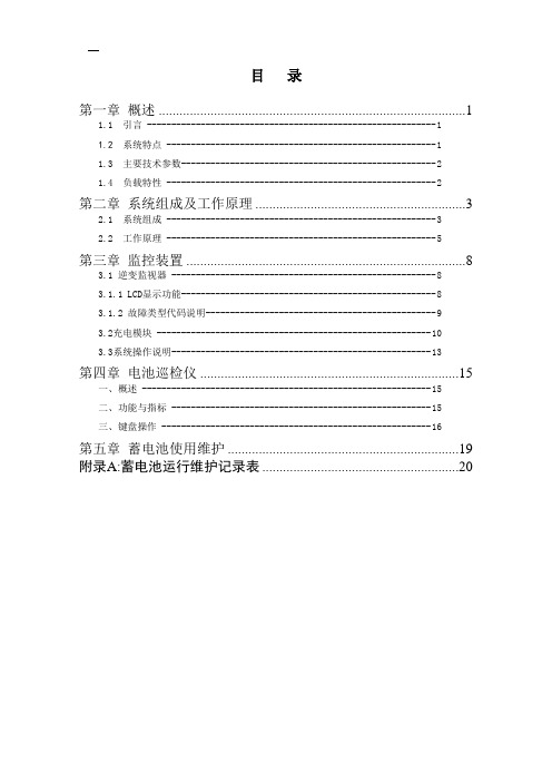
目录第一章概述 (1)1.1 引言 ----------------------------------------------------------- 11.2 系统特点 ------------------------------------------------------- 11.3 主要技术参数---------------------------------------------------- 21.4 负载特性 ------------------------------------------------------- 2第二章系统组成及工作原理 (3)2.1 系统组成 ------------------------------------------------------- 32.2 工作原理 ------------------------------------------------------- 5第三章监控装置 (8)3.1 逆变监视器 ------------------------------------------------------ 83.1.1 LCD显示功能--------------------------------------------------- 83.1.2 故障类型代码说明----------------------------------------------- 93.2充电模块-------------------------------------------------------- 103.3系统操作说明---------------------------------------------------- 13第四章电池巡检仪 (15)一、概述 ----------------------------------------------------------- 15二、功能与指标 ----------------------------------------------------- 15三、键盘操作 ------------------------------------------------------- 16第五章蓄电池使用维护 (19)附录A:蓄电池运行维护记录表 (20)第一章概述1.1 引言TEP系列微机应急电源系统,融合了最新的电力电子技术、高频软开关技术和计算机控制技术,具有简洁的全中文界面显示,完全智能化的运行管理和多层保护等优异特点和良好、稳定的运行性能,极大地提高了应急电源系统的稳定性、可靠性和效率,是创新的高科技能源产品。
高压发生器

操作及步骤
操作过程
操作前准备
保护的设定
将控制箱的输出电缆插座与倍压装置电缆插座用专用电缆连接好,本仪器由使用前检查其完好性,联接电缆 不应有短路和断路;倍压筒应无凝露现象;用2.5mm2以上的铜线将控制箱接地与倍压装置接地端连接起来并可靠 接地。
6)直流高压电压漂移:直流高压电压漂移是指电源电压不变,直流高压发生器在阻性负载的条件下,直流高 压调节器放在额定电压位置时,一定时间内直流高压的漂移值。
感谢观看
发生器特点
直流高压发生器是根据中国行业标准ZBF -90《便携式直流高压发生器通用技术条件》的要求,最新研究、 设计、制造的,是新时代的科技产品——便携式直流高压发生器,适用于电力部门、科研单位、铁路、化工、发 电厂、大型企业动力部门对氧化锌避雷器、磁吹避雷器、电力电缆、发电机、变压器、开关等设备进行直流高压 试验和泄漏电流试验。
在试品测试过程中按下0.75倍电压显示锁存按键,则0.75倍电压显示表显示值锁定,维持显示值不便,这样 在做氧化锌避雷器试验时很方便地可作为参考电压。在任何时候按下定时开按键,则启动时间继电器,在记时到 达预设的时间时,蜂鸣器发出报警讯响。在试验过程中,如果负载电流超过仪器额定输出电流的0-10%时,“过 流”指示灯亮,过流保护,防止损坏试品和仪器。
VLF 0.1HZ超低频高压发生器结合了现代数字变频先进技术,采用微机控制。升压,降压,测量,保护完全 自动化。并且在自动升压过程中能进行人工干预。由于全电子化。可广泛用于电缆,旋转电机,电力电容器的交 流耐压试验之中。
ZGF直流高压发生器使用手册
ZGF直流高压发生器使用手册第一章引言1.1产品概述DGF直流高压发生器是一种用于产生高压直流电的设备,主要用途包括工业领域的电磁兼容性测试、高压电源供应以及实验室科研等。
本手册将介绍DGF直流高压发生器的基本原理、功能特点、操作注意事项等内容。
1.2产品特点(1)输出电压范围广,可调节范围为0至3000V;(2)稳定性高,能够稳定输出高压直流电;(3)具备保护装置,包括过压保护、短路保护等;(4)操作简单,配备LCD显示屏,支持触摸功能;(5)具备远程控制接口,可与计算机进行连接,实现远程操作。
第二章安全指引2.1使用环境DGF直流高压发生器应在环境温度5~40℃,相对湿度<80%的条件下使用。
使用过程中应避免受潮、高温、腐蚀性气体等恶劣环境。
2.2电源要求接入电源前,应检查电源电压与设备额定电压是否匹配。
如果电源过电压或低电压,不得开机使用,以防损坏设备或引发危险。
2.3设备连接在进行设备连接前,应先确保电源已关闭,并拔掉电源插头。
各种接线操作应准确无误,严禁乱接线或接反。
2.4防触电措施不得在设备工作时,触摸设备内的任何零部件。
如需清洗设备或更换零部件,需要先切断电源,待设备完全停止运行后再进行操作。
第三章设备操作3.1开机和关机(1)接通电源,插好电源插头;(2)按下电源开关,设备将开始自检过程,待显示屏亮起后,系统进入待机模式;(3)长按电源开关,设备将关机。
3.2设置输出电压(1)按下输出电压设置按钮,进入电压设置界面;(2)通过上下箭头键调节输出电压,确认后按下设置键保存;(3)再次按下输出电压设置按钮即可退出设置界面。
3.3输出电压控制(1)按下输出电压控制按钮,进入电压控制界面;(2)通过上下箭头键调节输出电压大小,按下确定键确认设定值;(3)再次按下输出电压控制按钮即可退出电压控制界面。
第四章故障排除4.1无法开机(1)检查电源插座是否通电,插头是否接触良好;(2)检查电源是否过电压或低电压;(3)检查设备是否有损坏,是否有零部件松动。
SSB(JZ)5kVA50kV轻型交直流高压试验变压器说明书
SSB(JZ)5kVA50kV轻型交直流⾼压试验变压器说明书>>产品介绍-电⼒检修试验仪器仪表设备-试验变压器电话:021-******** 移动:156******** 传真:021-********转8002产品名称:SSB(JZ)5kVA/50kV轻型交直流⾼压试验变压器说明书产品应⽤:5kVA/50kV SSB(JZ)系列轻型交直流⾼压试验变压器说明书产品介绍:SB(JZ)系列轻型交直流⾼压试验变压器说明书⼀、产品概述SSB(JZ)系列轻型交直流⾼压试验变压器是⼀种新型⾼压测试设备,本系列产品采⽤单框芯式铁芯结构,初级绕组和⾼压绕组同轴绕制在铁芯上,从⽽减少漏磁通,增⼤绕组间的耦合。
产品的整体结构紧凑,通⽤性强,使⽤携带⽅便,适⽤于电⼒系统及电⼒⽤户在现场检测各种⾼压电器设备的绝缘性能,是电⼒设备检测及预防性试验所必备的试验仪器。
SSB(JZ)系列轻型交直流⾼压试验变压器除了可于交流⼯频耐压试验,如果配以同等电压等级和同等容量的电容、硅堆及⾼压直流微安表,便可组装成直流⾼压试验装置,可以测量⾼压直流泄漏电流。
⼆、型号含义三、原理图四、技术要求1、试验变压器使⽤环境要求:1.1 输⼊电压:交流220V或380V,50Hz;1.2 环境温度:-40℃~40℃;1.3 相对湿度:≤85%(环境温度为25℃时);1.4 不含有化学性⽓体及蒸汽的环境中;1.5 ⽆爆炸性危险的⽓体中;1.6 不受⾬⽔浸⼊的场合下。
2、技术参数型号规格容量(kVA)低压输⼊交流⾼压输出直流⾼压输出(kV)测量变⽐电压(V)电流(A)电压(kV)电流(mA)SSB(JZ)-5/505200255010070500 SSB(JZ)-10/5010200505020070500 SSB(JZ)-20/5020400285040070500 SSB(JZ)-30/5030400435060070500 SSB(JZ)-50/50504007250100070500 SSB(JZ)-10/10010200501001001401000 SSB(JZ)-20/10020400281002001401000 SSB(JZ)-30/10030400431003001401000 SSB(JZ)-50/10050400721005001401000 SSB(JZ)-100/10010040014410010001401000 SSB(JZ)-20/15020400281501332101000 SSB(JZ)-30/15030400431502002101000 SSB(JZ)-50/15050400721503332101000注: 1、我⼚SSB(JZ)系列试验变压器单台可做到交流300kV,容量300kVA;2、如果⽤户需要,我⼚⽣产的YDQ系列试验变压器,抽出200V的串级抽头,可将⼆台或三台串级成交流100kV、150kV、200kV、300kV的⾼电压。
英文版直流高压发生器说明书

User manual book--High V oltage DC GeneratorWarningPeople who use of this product must have a "high-voltage test certificate".Please read the 168 regulation of "electric power regulatory" when you use this product,and install two apparently disconnected point between power and the tester, when replacing the tester or Connecting line, you should break the two disconnect point of power supply.Check tester control box, the high-voltage cylinder and the grounding wire is connected together before testing. The grounding wire should be connected rightly to the earth.The large capacitor loader must discharged through the resistor of 100Ω/ V. Don’t contact the rod resistor with the loader immediately, you should put the rod resistor close to the sample gradually, keep a certain distance, and then discharge with hiss. When there is no sound, we can use rod resistor finally discharge by connecting to earth.If the loader is a capacitive loader, before test you must connect with resistor.When the voltage is more than 200kV, although the test personnel wear insulated shoes and at a safe distance from the outside area, but because of the effects of high voltage DC ion distribution of space electric field, it can lead to different DC potential of standing people nearby. Don’t handshake each other or touch any grounding body, otherwise there will be a mild electric shock phenomenon, this phenomenon happens in dry areas and winter commonly, but it generates little energy, so it can do no harm to people.After finishing the test, you must connect the grounding wire to the end of high voltage output, and then you can remove the lead wire off.CATALOGIntroduction (4)Principle of operation (4)Technical parameter (4)Function (7)Operation steps (9)Fault resolve (13)Product complete sets (13)Quality assurance (14)Service Promise (14)Introduction The high voltage DC generator is a new product designed according to the new China electric power industry standard DL / T848.1-2004 "DC high voltage generator general technical conditions". This product is mainly used for DC endure experiment to high voltage device such as Electric Power Cooperation, Metallurgy, Iron and Steel enterprises.Principle of operationAC 220outTechnical parameter1. Technical character● The control box is used of aluminum alloy structure.● It uses the new technology such as PWM pulse-wide modulation, middlefrequency high voltage and high power IGBT device.● It uses voltage feedback; output stability is less than 3%.● Full range of voltage output, voltage regulating accuracy is less than 1%, thestability of voltage error is less than 1.5%, the voltage error ± (1.5% ±2 words), the current error ± (1.5% ± 2 words).●Raise voltage from zero voltage potentiometer.●The 0.75UDC/1mA function button is convenient for zinc oxide arrester test, andthe accuracy is ±(3%±2words).●Over voltage protection uses dialing number set, and the error is ±1%.●High voltage cylinder is used of new materials, lightweight and sturdy. It’s co atedwith special insulating materials, electrical performance and moisture-proof ability is good.●The product conforms to DL / T848.1-2004 technology requirements, and passedthe center test of electrical equipment quality inspection, strictly according to the enterprise standard.2. Technical parametersNote: As the product update, we don’t notice any more, according to the sample, the company reserves the right of interpretation.Function(1)Control box Panel1、Ground terminal: When testing, the grounding terminal of control box and high-voltage cylinder should be connected together, and then connected with the earth. 2、Output port is used for the connection of the control box and high-voltagecylinder . We only rotate the cable pressing plug clockwise in place when connecting, only rotate the cable plug anti-clockwise when broking.3、V oltage setting switch: Used for setting the over-voltage protection value. Thedisplay unit of dial switch is kV, set values is 1.1 times of the test voltage.4、Power input socket: A random configuration of power line and the power inputsocket. (AC voltage 220V±10%, socket with fuse.)5、Digital voltage meter: Digital display high voltage DC output voltage.6、Digital current meter: Digital display high voltage DC output current.7、Power switch: Forward press, the power is on, the red lights, conversely toshutdown.8、Yellow light button: This function is designed for zinc oxide arrester formeasurement of 0.75UDc1mA. It’s effective when the green lights. After pressing the button, output voltage reduce to the original 0.75%, and keeps this state. Press the red button, red light and green light all out, high pressure cuts off and exits0.75 times state.9、The green button: High-voltage output button, high voltage indicator lamps. In redlight state, press the green button, the green light and red light out, this means high voltage circuit is switched on, then we can raise voltage. It’s Effective that thisbutton must be on voltage regulating potentiometer zero state. If press the green button, the green light is bright red, at the same time the red light is brighter, but release the green button, green light out and red light, it means Internal protection circuit has been working.10、Red button: the red light shows that the power is switched on and the high voltageis cut off .In the green state ,press the red button, red light is bright, high voltage is cut off.11、V oltage adjusting potentiometer: The potentiometer is a multi-turn potentiometer.Rotate clockwise to boost, and conversely to Step-down. The potentiometer has the function of controlling electronic zero protection, so must firstly return to zerobefore boosting.(2)High-voltage cylinder1、High voltage terminals (connect Microampere meter and water resistance orcurrent-limiting resistor)2、Equipotential shielding for HV3、High-voltage cylinder4、Grounding terminal5、Intermediate frequency output terminal6、Base(3)Testing connectionOperation steps(If capacitive load, should access the current-limiting resistor)1、 Check integrity before using the tester, make sure that there is no circuit breakeror short circuit in connecting cable, and equipment without rupture damage.2、Put the control box and High-voltage cylinder in place, then respectively connectpower line, control cable and grounding line ,protect all grounding wire separatelyconnecting to the sample point (one point tie to the earth ).Forbids the groundingwire connected in series. For this purpose, you should use the DHV specialgrounding wire.3、Keep power switch off and check voltage potentiometer at zero. Over voltageprotection setting value is generally 1.1 times of the testing voltage.4、No load ,step-up to verify the sensitivity of over voltage protection setting.5、Put power on, the red light, it means power on.6、Press the green button, then the green light, it means high voltage is outputting7、Regulate pressure regulating potentiometer clockwise direction smoothly, outputend is raised from zero to a desired voltage, according to the prescribed timerecording current meter readings, and check the control box and high voltageoutput line has no abnormal phenomenon or sound.8、 Reduce voltage ,regulate pressure regulating potentiometer to zero, then press )the red button, cut off the high voltage and then turn the power switch off.9、To test for leakage and DC voltage endurance, check test confirmation testerwithout exception, you can start test for leakage and DC voltage endurance test.Connect the test items and grounding wire, and then can open power s before thereis no mistake.10、Raise to the required voltage or current. The suitable raising speed is 3 - 5kV testvoltage per second. For large capacitance, we need to monitor of ammetercharging current not exceed the maximum charging current tester while raisingvoltage. For small capacitive products such as zinc oxide arrester, lightningarrester, we firstly raise to a desired voltage (current) at 95%, then slowly raiseto a desired voltage (current).From the digital display meter, we can read outvoltage (current) value. For zinc oxide arrester 0.75UDC - 1mA measurement, we firstly rise to UDC1mA voltage value, and then press the yellow button, when the voltage is reduced to the original 75%, and remains in this state. At this time, current value can be read. After the measurement, regulate pressure regulating potentiometer anticlockwise to zero, press the green button. Press green button.When you need raising voltage againYou can use external High Voltmeter to measure the output voltage if necessary.11、Reduce voltage and turn off the power after finish testing.12、Several methods for measuringa. Normal, when the wires are connected, suspend wires of tester, rising to thetesting voltage with no load ,Read stray current I’first, and then try to read the total currentⅠ1 with load, sample leakage current: Io =Ⅰ1—I’b.When we need an accurate measurement of sample leakage current, we should connect the high voltage micro ammeter to the high side (see below).Microampere meter must have a metal shielding; shielding line should be connected with test. The shielding of High voltage lead should be closely connected with end shielding. If the sample surface is dirty, we should exclude effect of samplesurface leakage current. In samples of high potential end, several times around with bare metal cords (see below).c.For sample such as zinc oxide, magnetic blow-out arrester, the grounding end can be breaked up; also can measure by connecting ammeter to the bottom (ground potential side) of test items. when we exclude effect of sample surface leakage current,we can use soft of bare copper wire in the sample to end the last laps around the shield ,and connect shielding line (see below)13、For small capacitive products ,such as zinc oxide and lightning arrester ,itdischarges quickly through pressure resistance. For large capacitive products such as cable, while test voltage self discharging to the test voltage is below 20%, then it can discharge by supporting the discharging rod. Keep connect the grounding wire to the capacitive products before voltage discharging completely, and then we can remove high voltage lead and other wire.14、If green light is off, red light is bright, voltage is dropping, which is relatedprotection to the product .You should turn off the power switch, panel lights are not bright. Turn the pressure regulating potentiometer to zero position, while low voltage capacitor discharging completely, then open the power switch a minute later. If you start a no loading test again, you can begin raising voltage test before checking all situations.Fault resolveComplete sets of products1. Control box 12. High-voltage cylinder 13. Use’s manual book 14. Fuse some5. Power cable 16. Special grounding wire 17. Discharging rod 18. Water resistance or current limiting resistor 19. Microampere ammeter 1Quality assurance1. The equipment made by the company can meet the requirements of the buyer, andprovide free pre-sale technical services.2. Products of the company have effective inspection and control, strictly productaccording to ISO9001 quality system of production service.3. The quality of our products is according to the standards of our company andrelevant national standards.Service PromiseThe product’s warrant time is one year, the implementation of "Three Guarantees", life-long repairing, all of the equipment of the company quality problem, we can provide free repair in the warranty period. Improper operation due to the user or accidental damage, we can provide preferential services. We’ll be looking forward to your valuable opinions to our products.。
最新直流高压发生器说明书
最新直流⾼压发⽣器说明书⽬录⼀、安全警告 (1)⼆、简介 (2)三、⼯作原理框图 (2)四、主要技术参数特点 (3)五、产品功能说明 (5)六、操作步骤 (7)七、故障检查与处理 (9)⼋、产品成套性 (10)九、售后服务 (10)感谢您使⽤本公司产品!使⽤前请务必仔细阅读使⽤说明书!为了您尽快熟练地操作本仪器使⽤⽅法,以确保安全使⽤!⼀、安全警告●使⽤直流⾼压试验器的⼯作⼈员必须是具有“⾼压试验上岗证”的专业⼈员。
●使⽤本仪器请⽤户必须按《电⼒安规》168条规定,并在⼯作电源进⼊试验器前加装两个明显断开点,当更换试品和接线时应先将两个电源断开点明显断开。
●试验前请检查试验器控制箱、倍压筒和试品的接地线是否接好。
试验回路接地线应按本说明书所⽰⼀点接地。
●对⼤电容试品的放电应经100Ω/V放电电阻棒对试品放电。
放电时不能将放电棒⽴即接触试品,应先将放电棒逐渐接近试品,⾄⼀定距离空⽓间隙开始游离放电有嘶嘶声。
当⽆声⾳时可⽤放电棒放电,最后直接接上地线放电。
●如做容性负载试验时,⼀定要接上限流电阻。
●直流⾼压在200KV及以上时,尽管试验⼈员穿绝缘鞋且处在安全距离以外区域,但由于⾼压直流离⼦空间电场分布的影响,会使⼏个邻近站⽴的体上带有不同的直流电位。
试验⼈员不要互相握⼿或⽤⼿接触接地位等,否则会有轻微电击现象,此现象在⼲燥地区和冬季较为明显,但由于能量较⼩⼀般不会对⼈造成伤害。
●试验完毕必须将接地线挂⾄⾼压输出端⽅可拆除⾼压引线。
⼆、简介RTZG-60kV/5mA直流⾼压发⽣器是根据新的中国电⼒待业标准DL/T848.1-2004《直流⾼压发⽣器通⽤技术条件》设计制造的新⼀代便携式直流⾼压发⽣器。
主要适⽤于电⼒部门、⼯矿、冶⾦、钢铁等企业动⼒部门对氧化锌避雷器、电⼒电缆、变压器、发电机等⾼压电⽓设备进⾏直流耐压试验。
三、⼯作原理框图四、主要技术参数特点1、技术特点:●机箱采⽤铝合⾦机箱。
●采⽤中频倍压电路,应⽤PWM脉宽调制技术和⼤功率IGBT器件。
#Q系列直流高压发生器说明书
®Q系列直流高压发生器使用说明书苏州华电电气股份有限公司安全警告●使用直流高压试验器的工作人员必须是具有“高压试验上岗证”的专业人员。
●使用本仪器请用户必须按《电力安规》168条规定,并在工作电源进入试验器前加装两个明显断开点;当更换试品和接线时应先将两个电源断开点明显断开。
●试验前请检查试验器控制箱、倍压筒和试品的接地线是否接好。
试验回路接地线应按本说明书(图4)所示一点接地。
●对大电容试品的放电应经100Ω/V放电电阻棒对试品放电。
放电时不能将放电棒立即接触试品,应先将放电棒逐渐接近试品,至一定距离高空气间隙开始游离放电.有嘶嘶声:当无声音时可用随电棒放电,最后直接接上地线放电。
目录一、简介二、工作原理框图三、主要技术性能四、使用说明五、操作步骤六、故障检查与处理七、产品成套性八、选购件一、简介ZGS-Q系列直流高压试验器是苏州华电充分吸取用户的宝贵意见,潜心研究而推出的新一代产品。
在保留了ZGSⅡ一些特点的基础上,作了如下重大改进:①采用了电压大反馈,因此输出电压稳定度得到大幅度提高,电压漂移量极小;②大幅度提高了频率,使纹波系数更小;③增设了高精度0.75U DC-1mA功能按钮,给氧化锌避雷器测量带来了极大的方便;④高压过压整定采用数字拨盘开关,能将整定电压值直观显示,并具有较高的整定精度;⑤输出电压调节采用单个多圈电位器,升压过程平稳,调节精度高,操作简单;⑥与此同时,根据电磁兼容性理论,采用特殊屏蔽、隔离和接地等措施从而保证试验器能承受额定电压放电不损坏。
ZGS-Q 系列采用了独特的一体化机箱结构。
使用时倍压与控制箱可分离,既方便携带,又安全可靠。
体积重量大为减少。
本试验器广泛适用于对氧化锌避雷器、磁吹避雷器、电力电缆、发电机、变压器、开关等设备进行直流高压试验。
二、工作原理框图1 工作原理框图规格Q- 60/2 Q- 60/3 Q- 80/2 Q- 80/3技术参数输出电压(kV) 60 60 80 80输出电流(mA) 2 3 2 3输出功率(W) 120 180 160 240充电电流(mA) 4 5 4 5 (mm2) 400×400×180 400×400×180 450×400×180 450×400×180(kg) 7.8 8.0 8.3 8.5电压测量误差1%(满度)±1个字电流测量误差1%(满度)±1个字过压整定误差≤1%切换误差≤1%波纹系数≤0.5%电压稳定度随机波动、电源电压变化±10%,≤0.5%四、使用说明(一)面板图2 ZGSQ(Ⅲ型)1.数显电流表:数字显示直流高压输出电流。
电压击穿50KV说明书

-电压击穿试验仪目录一、概述 (1)二、技术指标 (1)2.1技术指标说明 (1)2.2专用术语说明 (1)三、安全说明 (2)四、整机组成 (2)五、操作步骤 (3)5.1电压击穿试验计算机部分操作步骤 (3)5.2电压击穿试验屏幕部分操作步骤 (5)5.2.1两种试验方式介绍: (5)5.2.2三种试验方法介绍: (6)六、试验准备和环境 (10)1、试样的处理 (10)2、.媒质: (10)3、试验环境: (10)七、使用前须知 (12)八、常见可能的故障及处理方法 (12)一、概述电压击穿试验仪是测试有关产品耐电压击穿强度的重要仪器。
依靠该仪器提供的模拟试验条件,可以直观,准确。
快速。
可靠地对各种被测对象进行击穿电压,漏电流等各项测试。
仪器采用计算机操控,可以方便地把试验结果进行数据存储、处理.曲线显示及打印。
本仪器经过多年不断改进完善,日趋成熟,具有很高的安全性和可靠性,受到了用户的好评。
(本仪器系我公司国内首创,至今已有20余年制造经验。
内含多项国家专利的产品)仪器生产参考如下标准:ASTMD149-97:电介质击穿电压及绝缘强度,导电性能试验。
(美国材料与试验协会标准)GB/T1408__2006:绝缘材料电气强度试验方法GB/T1695_2005:硫化橡胶工频电压击穿强度和耐电压试验。
GB/T3333:电缆纸工频电压击穿试验方法;GB/T12656:电容器纸工频电压击穿试验方法HG/T3330:绝缘漆漆膜击穿强度测定法。
二、技术指标2.1技术指标说明输入电压:AC 220V±10%电源频率:50-60Hz高压变压器功率:3kVA调压器功率 3kVA输出电压:AC 0~50kV ,DC 0~50kV测量精度:±3%量程:0~50kV升压方式选择功能:1;连续升压;2;逐级升压;3;瞬时升压。
升压速率设定功能。
(KV/S)0.2 0.5 1外形尺寸:630mm*520mm*760mm(50kV产品); 1570mm*1240mm*1850mm(100kV产品)2.2专用术语说明1、击穿电压(V):用连续均匀升压的办法对试样施加工频电压并保持试样发生击穿时的电压值,以kV表示。
艾斯科 BD-50E高频发生器使用说明书

4642 N. RAVENSWOOD, CHICAGO, ILLINOIS 60640-4510TELEPHONE: 1-773-561-2349FAX: 1-773-561-3130Model BD-50E HIGH FREQUENCY GENERATOROPERATING MANUALDESCRIPTION. The Model BD-50E is a rugged tester designed for testing tank lining and other applications where extended use is necessary. The unit is operated by a transformer which limits the current and isolates the unit from the power line for safety protection. The low voltage (magnet coil) and high voltage (resonator coil) are separated, making the unit run cooler than the hand-held models. This also allows for an extended period of use, up to no more than about 3 hours of use, with a similar cool down period.It has a peak output voltage of between 20,000 to 50,000 V, ±2 kV, at a frequency of 0.5 MHz. The current output is approximately 1 mA.The Output Adjustment Knob is graduated from 1 to 11. The actual output voltage will vary depending upon the electrode used, as a larger electrode will load down the unit. Also, there is some variation in output from unit to unit, and will vary depending upon the condition of the vibration contacts inside the unit. Worn contacts will decrease the output. As a rule however, these are the approximate outputs that can be expected from a unit that is operating properly: POSITION N0. 1 3 5 7 9 11 Voltage 20,000 27,000 32,000 38,000 43,000 49,000Four models are available for different input voltages:Model BD-50E (SKU 15001), 115 V, 50/60 Hz, with 12101 Electrode Tip .Model BD-50EV (SKU 15021xx-10), 230 V, 50/60 Hz, with 12101 Electrode Tip. Model BD-50ET Tank Lining Tester Kit (SKU 15031), 115 V, 50/60 Hz, with 12101, 12131, and 12141 Electrode Tips. A carrying case is optional.Model BD-50EV Tank Lining Tester Kit (SKU 15061xx-10), 230 V, 50/60 Hz, with 12101, 12131, and 12141 Electrode Tips. A carrying case is optional.The 115 V model is also available equipped with a power line filter for use around sensitive electronic equipment (SKU 15001-10, and 15031-10).The “V” in the Model Number, BD-50EV, designates a line cord plug for use for 230 V input. The “xx” designates the line cord plug type furnished with models typically used outside of North America. All of these 230 V models are equipped with a power line filter.A 6 ft. (1.8 m) cable from the control box to the high voltage handle is provided with standard, but a longer cable, up to 15 ft. (4.5 m) can be special ordered. Contact Electro-Technic for specific details and ordering information. INSTALLATION. A standard tip electrode, Part No, 12101, illustrated above, but not below is included with each model. To install it, press it into the tip of the generator handle. To remove, grasp its base firmly, and with a gentle twisting motion, pull out from the generator tip. Never insert or remove the electrode while power is on.Accessory Electrodes for the Model BD-50E12111 Spring Tip12121 T-Tip12131 T-Tip, 12 in. Wide12141 Fan Tip12401 Brush Tip4 in. Wide 4 in. Wide12421 Brush Electrode, 8 in. WideThese electrodes, plus the 12101 Standard Tip, are the only factory approved electrodes for the Model BD-50E. No other electrodes should be used.After the electrode is inserted, plug the power line cord into its matching receptacle, providing the proper voltage for the unit, either 115 V or 230 V.OPERATION.1) Turn the Output Adjustment Knob fully counterclockwise, and then turnthe Power Switch to its ON position.2) Turn the Output Adjustment Knob clockwise to adjust the voltage forthe desired spark length. Hold the tip close to the chassis of the unit,or a common ground point, to observe and adjust the length of thespark. For thick materials, the spark should be adjusted for nearmaximum length. For very thin materials, a shorter spark is desired. Aone inch spark represents a peak voltage of approximately 50,000volts.3) When the tip is scanning close to a metal surface, there will be apurple color spark, or corona discharge glow.4) Once the unit is adjusted, pass the electrode over the material beingtested. The electrode can be passed directly over most materials,however, with thin linings, keep the electrode no more than 1/8 in.above the surface being tested.Photo at left shows a pin holelocated in a sheet of rubber,with a metal backing, using the12141 Fan Tip Electrode5) When the electrode passes over a pinhole, crack, or similar type flaw,observe a bright white, concentrated spark jumping from the electrodeto the metal, or similarly conducting surface below the lining or coating.A reprint of an article showing a flaw being detected is included withthese instructions.SAFETY PRECAUTIONS.It is used in industrial applications for pinhole leak detection, and toionize a gas inside a bulb or similar device to determine whether a goodvacuum is being held inside the device. It is also used as a lamp starter,principally in printing industry.Only factory approved electrodes should be used. No other electrodesshould be used with this device. Never operate without an electrode.Never touch or come in contact with the high voltage output of thisdevice, nor with any device it is energizing.Since its output is 500 kHz, it radiates its energy for a short distance.It may interfere with sensitive electronic devices near by. If a user iswearing a pace maker or similar device, their physician should becontacted prior to using this device. The same should be said forwomen who are pregnant.A small amount of ozone gas is generated as a by-product. Use in awell-ventilated area.Do not operate out of doors on in or around a flammable or explosiveenvironment.CALIBRATION SERVICE. Factory calibration service is available for a nominal charge. It includes test data for all output positions with a number of electrodes, and is traceable to a NIST standard. Yearly calibration is recommended. Request a Return Authorization Number prior to returning to the factory for calibration.MAINTENANCE / INSPECTIONS. If the output level of the Model BD-50E is required to be verified when this instrument is in use, check the output with a Model 12701 Peak Voltage Calibrator, shown below.The only component in this equipment that should be checked is the vibrating contacts that make and break the circuitry, generating the high frequency. These contacts, made of a tungsten alloy, erode with use. Eventually, they erode to a point where the output of the unit decreases.If the Model BD-50E receives light duty use, and is otherwise functioning properly, an annual inspection is recommended. If the unit is used on a frequent basis, has been dropped, or the maximum output is found to be decreasing, then a quarterly inspection is warranted.To check the contacts, with the power removed from the unit, remove the cover and visually check the contacts for carbon built-up, burn marks, excessive pitting or erosion. Also check that the contacts are aligned properly.To replace the contacts, remove the magnet coil assembly. Loosen the locking nut and back up the screw all the way back. Remove the top assembly and then remove the top contact and then the bottom contact assembly.Replace the bottom contact assembly, making sure that enough room is left between the bottom contact and the magnet coil top, so that the armature can vibrate freely, with about 0.035 to 0.040 in. clearance.Replace the top contact assembly, making sure that the two contact points will be aligned with each other when they are pushed together.Reinstall the top assembly and then the magnet coil assembly.CAUTION. Take precautions not to touch any wires, as power to beunit will have to be applied with the cover removed to perform thisoperation.To adjust the contacts use a screw driver to turn the adjusting screw to push the contacts until there is a spark between the contacts, the contacts are aligned, and that the armature is vibrating freely.Then tighten the nut, reinstall the screw cap and the cover.Recheck the output with the Model 1270 Peak Voltage Calibrator.If you should have any further questions, contact Electro-Technic Products, Inc. for additional technical assistance.TROUBLESHOOTING AND REPAIR. There are no user serviceable parts inside the unit. In the event that the unit requires service, send it back to the factory. However, parts are available separately, so an experienced electronics technician can make repairs. The following troubleshooting guide is furnished: Check all connections for loose or broken wires. If the pilot light does not come on, check for shorts and for input voltage at the fuse. If fuse is blown, replace it with a 3/4 A Slo-Blo for 115 V units, and ½ A Slo-Blo for 230 V units.If the fuse is Okay, check the power cord for shorts, and replace if necessary. Test the ON/OFF Switch.If the pilot light comes on, check the transformer for voltage between the secondary leads. If voltage is Okay, then check the magnet coil for resistance between 65 to 72 ohms for 115 V units, and 262 to 270 ohms for 230 V units. Check the contacts for the presence of a spark. If no spark, move the adjusting screw clockwise or counterclockwise. If the spark comes on, the unit is Okay. If not, check the printer circuit board for shorts and clean the contacts at the positions of the switch. If this does not solve the problem, replace the board. If the contacts of the magnet coil are working Okay, but there us still no output at the electrode tip, and the power supply to handle wire is Okay, then replace the resonator coil.REPAIR PARTS. The following are repair parts for the BD-50E models. Contact the factory for price and availabilityPart Number Description12101 Electrode Tip002-0005-1 Nut, 10-32, Hex, for Electrode Socket010-0003-1 Isolation Transformer, 115 V010-0012-1 Transformer, Step Down, 230 to 115 V011-0008-1 Magnet Coil011-0023-1 Choke Coil Assembly011-0024-1 Resonator Coil Assembly021-0053-1 Capacitor, 0.1 uF, 800 V023-0027-1 Power Supply / Generator Cord, 6 ft min., 15 ft. max025-7532-1 Printed Circuit Board Assembly025-0032-1 Printed Circuit Board027-0065-1 Power Line Filter028-0002-1 Pilot Light029-0002-1 Fuse Holder029-0024-3 Fuse, 1/2 A, Slow-Blow, for 230 V Models029-0030-1 Fuse, 3/4 A, Slow-Blow, for 115 V Models029-0085-1 Switch, Rotary, Heavy Duty033-0006-1 Cover, for Cabinet033-7005-3 Cabinet, without Cover035-0003-1 Top Spring Rivet Contact Assembly035-0017-1 Armature Assembly035-0008-1 Bridge, with Posts, Ratchet, and Adjusting Screws044-0003-1 Top Housing, Bakelite, Cone044-0004-1 Bottom Housing, Bakelite044-0007-1 Molded Spool Core044-0011-3 Adjusting Knob, w/Line045-0003-1 Electrode Socket049-0001-1 Cabinet Handle Assembly049-0025-1 Nut Driver, 5/16 in.050-0037-1 Tungsten Screw Contact050-0079-1 Cover Cap, Brass051-0001-1 Spacer, Teflon053-0003-1 Standoff, Nylon059-0040-1 Switch, Toggle, SPST, w/leads attached060-0002-1 Line Cord Set, 3 Conductor, 115 V060-000X-1 Line Cord Set, 3 Conductor, 230 V, Specify Type060-0100-1 Ribbon Cable Choke Assembly070-0059-3 Carton. Packing, with Insert080-1500-1 Handle Assembly (Resonator), with 6 ft. CordSpecial Note Regarding CE Marking. The Model BD-50EV generates a high voltage corona of approximately 500 kHz. However by the very nature of its design, it will produce electromagnetic interference (EMI) as a result of its operation. Electric arc welders, for example, are another product that by its very nature and mode of operation produces EMI.As a result, the Model BD-50EV cannot meet the European Union Electromagnetic Compatibility (EMC) Directive 89/336/EEC, and cannot be CE marked.It does, however, meet EN61010-1:1993 Safety Requirements for Electrical Equipment for Measurement, Control and Laboratory Use, following the provisions of the Low Voltage Directive 73/23/EEC, as amended by 93/68/EECBecause of the risk of EMI, a risk assessment should be carried out prior to use of this equipment.The power output of the Model BD-50EV is limited. The effective range of EMI is less than about 1 meter on so in all directions. Metal objects nearby may bend or deflect this radiation. Therefore, there is some risk that it might interfere with electronic equipment 1 meter or so from this apparatus. This might include telephones, computers, cell phones, for example. Operators who wear pacemakers may also wish to consult with a physician prior to using this equipment.If interference with equipment is detected, move the Model BD-50EV further away, or schedule its operation when the affected equipment is not in operation. Consult plant safety personnel regarding its use.If you should have any further questions, contact Electro-Technic Products, Inc. for additional technical assistance.。
直流高压发生器使用说明书
-1-尊敬的顾客感谢您使用本公司生产的产品。
在初次使用该仪器前,请您详细地阅读使用说明书,将可帮助您正确使用该仪器。
我们的宗旨是不断地改进和完善公司的产品,因此您所使用的仪器可能与使用说明书有少许差别。
若有改动,我们不一定能通知到您,敬请谅解!如有疑问,请与公司售后服务部联络,我们定会满足您的要求。
试线、电源插座时,会产生电火花,小心电击,避免触电危险,注意人身安全!-1-安全要求请阅读下列安全注意事项,以免人身伤害,并防止本产品或与其相连接的任何其它产品受到损坏。
为了避免可能发生的危险,本产品只可在规定的范围内使用。
只有合格的技术人员才可执行维修。
—防止火灾或人身伤害使用适当的电源线。
只可使用本产品专用、并且符合本产品规格的电源线。
正确地连接和断开。
当测试导线与带电端子连接时,请勿随意连接或断开测试导线。
产品接地。
本产品除通过电源线接地导线接地外,产品外壳的接地柱必须接地。
为了防止电击,接地导体必须与地面相连。
在与本产品输入或输出终端连接前,应确保本产品已正确接地。
注意所有终端的额定值。
为了防止火灾或电击危险,请注意本产品的所有额定值和标记。
在对本产品进行连接之前,请阅读本产品使用说明书,以便进一步了解有关额定值的信息。
请勿在无仪器盖板时操作。
如盖板或面板已卸下,请勿操作本产品。
使用适当的保险丝。
只可使用符合本产品规定类型和额定值的保险丝。
避免接触裸露电路和带电金属。
产品通电时,请勿触摸裸露的接点和部位。
在有可疑的故障时,请勿操作。
如怀疑本产品有损坏,请本公司维修人员进行检查,切勿继续操作。
请勿在潮湿环境下操作。
请勿在易爆环境中操作。
-2-保持产品表面清洁和干燥。
-安全术语警告:警告字句指出可能造成人身伤亡的状况或做法。
小心:小心字句指出可能造成本产品或其它财产损坏的状况或做法。
-3-实验之前安全注意事项1、使用直流高压发生器的工作人员必须是具有“高压试验上岗证”的专业人员。
2、使用本仪器请用户必须按《电力安规》168条规定,并在工作电源进入直流高压发生器前加装两个明显断开点,当更换试品和接线时应先将两个电源断开点明显断开。
Jameco M50D高压冲击电路器件说明书

•H igh S urge C urrent R e c tifier C ir c uit s•U p to 1600 V olt B lo c king S tandardFastFax Document No. 232SERIES M50D Rev. 111303 PAGE 1 OF 2Single- and three-phase diode circuits incorporate highly efficient thermal management to provide high surge capability, extended life, and reliable performance. Available in five circuits,all models come in an industry standard package, provide 2500 Vrms from all terminals to the baseplate, and are UL recognized (file no. E72445).Manufactured in Crydom's ISO 9002Certified facility for optimum product performance and reliability.0.20 (5.1) DIA.E L E C T R I C A L SPE C IF I C A T ION SRATINGSSYMBOL SPECIFICATIONM5060M50100I DMaximum DC Output Current (Tc = 85ûC )60A100AV F Maximum Voltage Drop @ Amps Peak 1.35V @ 60A1.2V @ 100AT JOperating Junction Temperature Range-40C to +125C 400 (120 Vac)600 (240 Vac)V RRM(Repetitive Peak Reverse Voltage (AC Line)1000 (380 Vac)1200 (480 Vac)1400 (530 Vac)1600 (600 Vac)I TSMMaximum Non-Repetitive Surge Current (1/2Cycle, 60Hz)800A 1500A I 2T Maximum I 2T for Fusing (t=8.3ms) [A 2sec]26509350R θJC Maximum Thermal Resistance Junction to Ceramic Base per Chip 0.45C /W 0.3C /W V ISOLIsolation Voltage2500 V RMS 2500 V RMSM E C HANI C A L SPE C I F I C A T ION SWeight: (typical)4.5 oz. ( 158g)M E C HANI C A L DIM E N S ION SAll dimensions are in inches (millimeters)P A R T NUM B E R ID E N T IF I C A T IONS erie s T ype C urre nt C ir c uit T ypeV ol tageM5060- 60 Amps (see schematic 400(120Vac)1200(480Vac)100- 100 Ampsdiagrams)600(240Vac)1400(530Vac) Example: T B1000(380Vac) 1600 (600Vac)E xample : M50100T B 1200©2003 CRYDOM CORP Specifications subject to change without notice.For recommended applications and more information contact:USA: Sales Support (877) 502-5500 Tech Support (877) 702-7700 FAX (619) 710-8540Crydom Corp, 2320 Paseo de las Americas, Ste. 201, San Diego, CA 92154Email :****************WEB SITE: UK: +44 (0)1202 365070 • FAX +44 (0)1202 365090 Crydom International Ltd., 7 Cobham Road, Ferndown Industrial Estate, Ferndown, Dorset BH21 7PE, Email :*******************.GERMANY: +49 (0)180 3000 506S e r i e s M 50 D i od e60-100A m p • D I O D E M odu l e sFastFax Document No. 232 SERIES M50DRev. 111303PAGE 2 OF 2•H igh S urge C urrentR e c tifier C ir c uit s•U p to 1600 V olt B lo c king Standard--ACAC--CCT H CDDACACAC+P A R T NUM B E R ID E N T I F I C A T IONS erie s T ype C urre nt C ir c uit T ype V ol tageM5060- 60 Amps(see schematic400(120Vac)1200(480Vac)100- 100 Amps diagrams)600(240Vac)1400(530Vac)Example: T B1000(380Vac) 1600 (600Vac)E xample: M50100T B1200M50 DIOD E C I RC UI T S©2003 CRYDOM CORP Specifications subject to change without notice.For recommended applications and more information contact:USA:Sales Support (877) 502-5500 Tech Support (877) 702-7700 FAX (619) 710-8540Crydom Corp, 2320 Paseo de las Americas, Ste. 201, San Diego, CA 92154Email:****************WEB SITE: UK: +44 (0)1202 365070 • FAX +44 (0)1202 365090 Crydom International Ltd., 7 CobhamRoad, Ferndown Industrial Estate, Ferndown, Dorset BH21 7PE, Email:*******************.GERMANY: +49 (0)180 3000 506S e r i e s M50D i od e60-100A m p•D I O D E M odu l e s。
高频高压发生器50kW

2.1.1.1 配置:2.1.1.1.1 高频高压发生器:50kW;数量:1。
2.1.1.1.2 操作键盘:液晶显示;数量:12.1.1.1.3 控制电缆:8m;数量:1。
2.1.1.1.4 高速球管:50kW;数量:1。
2.1.1.1.5 非晶硅DR板:17″×17″;数量:1。
2.1.1.1.6 DR专用滤线栅:80LP/cm;数量:1。
2.1.1.1.7 球管支柱/摄影床:多功能;数量:1。
2.1.1.1.8 图像采集微机:数量:1。
2.1.1.1.9 图像诊断微机:数量:1。
2.1.1.1.10 采集显示器:1M19″液晶显示器;数量:1。
2.1.1.1.11 诊断显示器:2M黑白液晶显示器;数量:1。
2.1.1.1.12 采集软件:DR专用;数量:1。
2.1.1.1.13 诊断软件:DICOM图像通用;数量:1。
2.1.1.1.14 高压电缆:12m;数量:2。
2.1.1.1.15 语音传输装置:双向传输;数量:1。
2.1.1.1.16 医用干式激光打印机:数量:1。
★2.1.1.2 非晶硅DR采集板(整板非拼接)灰阶深度14bit。
2.1.1.2.1 采集矩阵:≥3K×3K。
★2.1.1.2.2 像素间距:≤139um。
★2.1.1.2.3 采集尺寸:≥17″×17″。
2.1.1.2.4 分辨率:3.4LP/cm。
2.1.1.3 高压发生器:★2.1.1.3.1 逆变频率:≥200kHz。
2.1.1.3.2 功率:≥50kW。
2.1.1.3.3 输出电压:≥150kV。
2.1.1.3.4 最大毫安秒:≥630mAs。
2.1.1.3.5 最短时间:≤1ms。
2.1.1.4 高速球管:2.1.1.4.1 焦点功率:小焦≥27kW;大焦≥75kW。
2.1.1.4.2 焦点尺寸:≤0.6mm/1.2mm。
2.1.1.4.3 阳极转速:≥8100转/分。
2.1.1.4.4 靶面热容量:≥300Khu。
高压电力电容器说明书

1 、概述1.1本说明书使用于频率50HZ或60HZ交流电力系统用并联电容器(以下简称电容器),该种电容器主要用来提高电网功率因数,降低线损,改善电压质量,节约电费,提高变压器效率,充分发挥发电,供电设备的效率。
1.2电容器有GMKP/BFF型、GMKP/BFM型、GMKP/BAM型等系列,常用为GMKP/BFM型(全膜二芳基乙烷),其型号意义如下:GMKP/------- 包括法兰克公司系列代号,液体介质代号,固体介质代号,设计代号第一特征号,第二特征号,第三特征号,尾注号。
例如:(1)GMKP/BFM6.3-50-1,6.3Kv,50Kvar,单相,浸二芳基乙烷,全膜.(2 ) GMKP/BFMr11-100-3W,11Kv,100Kvar,三相,浸二芳基乙烷,全膜.(3 ) GMKP/BAMr11/√3-200-1Wh,11/√3Kv,200Kvar,单相,横放型,浸苄基甲苯,全膜.1.2.1系列代号B:表示并联电容器。
1.2.2液体介质代号F:表示二芳基乙烷,A:表示苄基甲苯(适用寒冷低温地区)。
1.2.3固体介质代号F:表示膜纸复合介质,M:表示全膜介质。
1.2.4设计代号R:表示放电电阻,r:表示内熔丝。
1.2.5第一特征代号(额定电压)6.3:表示额定电压6.3Kv,11:表示额定电压11Kv1.2.6第二特征代号(额定容量)50:表示额定容量50Kvar,100:表示额定容量100Kvar。
1.2.7第三特征代号(相数)1:表示单相,3:表示三相。
1.2.8尾注号W:表示户外式(不表示户内式),H:表示横放。
2、主要性能指标2.1电容器安装运行地区环境温度范围为-40℃~+45℃,其中GMKP/BFF、GMKP/BFM型电容器为-25℃~+45℃。
其余为-40℃~ +45℃。
海拔高度不超过1000米。
对安装地点高度超过1000米的电容器,订货时应特别加以说明。
2.2电容器的主要技术数据和外形尺寸见表5和附图。
超低频高压发生器使用说明书

VLF说明书武汉南偌电气有限公司湖北省·武汉市·东湖技术开发区光谷大道58号光谷总部国际4栋8楼声明南偌电气有限公司版权所有,保留所有权利。
本使用说明书所提及的商标与名称,均属于其合法注册公司所有。
本使用说明书受著作权保护,所撰写的内容均为公司所有。
本使用说明书所提及的产品规格或相关信息,未经许可,任何单位或个人不得擅自仿制、复制、修改、传播或出版。
本说明书所提到的产品规格和资讯仅供参考,如有内容更新,恕不另行通知。
除非有特殊约定,本说明书仅作为使用指导,本说明书中所有陈述、信息等均不构成任何形式的担保。
目录一、超低频绝缘耐压试验原理 (1)二、产品简介 (1)三、超低频系列产品及选用 (2)四、技术参数 (3)五、仪器结构说明 (4)六、操作说明 (6)七、电缆的超低频耐压试验方法 (9)八、发电机、电动机的超低频耐压试验方法 (11)九、注意事项 (12)十、随机附件 (12)一、超低频绝缘耐压试验原理超低频绝缘耐压试验实际上是工频耐压试验的一种替代方法。
我们知道,在对大型发电机、电缆等试品进行工频耐压试验时,由于它们的绝缘层呈现较大的电容量,所以需要很大容量的试验变压器或谐振变压器。
这样一些巨大的设备,不但笨重,造价高,而且使用十分不便。
为了解决这一矛盾,电力部门采用了降低试验频率,从而降低了试验电源的容量。
从国内外多年的理论和实践证明,用0.1Hz超低频耐压试验替代工频耐压试验,不但能有同样的等效性,而且设备的体积大为缩小,重量大为减轻,理论上容量约为工频的五百分之一,且操作简单,与工频试验相比优越性更多。
这就是为什么发达国家普遍采用这一方法的原因。
国家发改委已制定了《35kV及以下交联聚乙烯绝缘电力电缆超低频(0.1Hz)耐压试验方法》行业标准。
我国正在推广这一方法,本仪器是根据我国这一需要研制而成的。
可广泛用于电缆、大型高压旋转电机的交流耐压试验之中。
二、产品简介本产品接合了现代数字变频先进技术,采用微机控制,升压、降压、测量、保护完全自动化。
高压发生器

2021/10/10
25
中、高频机特点
7、 便于智能化
高频机使用单片机对整机进行控制和管理,这 和工频机相比有着显著的不同,单片机的应 用将高频机的各种性能提高到一个崭新的水 平。
2021/10/10
23
中、高频机特点
4、实时控制:曝光过程中可对kV和mA进行实时控制。 5、高压变压器的体积小、重量轻
根据变压器的工作原理,变压器初级线圈的匝数和铁芯截面积 的乘积与初级电压和电源频率之间的关系为:
NS=E/4.44fB
公式中:N为初级匝数;S为铁芯截面积;E为初级电压;f 是工作频率;B为磁感应强度。由于f越大,NA就越小,因 此高频高压发生器比工频高压发生器的体积和重量要小得多, 这一优点对生产便携式和移动式x线机非常有利。
高压电缆的主要参数是耐压值,高压电缆的最 大允许耐压值与KV的波形有关。
交流成分越大,最大容许耐压值就越小。
2、高压插头与插座。
它们工作在高电压下,对耐压的要求很高。
目前各厂家生产的高压插头与插座都采用国
际标准,可通用、互换。
2021/10/10
12
高压交换匣
1、较大功率的诊断X线机,为适应不同诊断工 作的需要,多配有两只或两只以上的X线管。
高压发生器组成部分:
1、高压变压器、X线管灯丝变压器、高压整流 器、高压交换匣,高压插座等元器件。
2、按要求组装后,置于方形或圆形钢板制成 的箱体内。
箱体内充变压器油,以加强各器件之间的绝 缘和散热,箱体应接地,以防高压电击造成 的危害。
SI-50 50MHz 高压差分探头用户手册说明书

SI-5050MHz HIGH VOLTAGE DIFFERENTIAL PROBEUSER’S MANUAL1. Safety Terms and SymbolsTerms appear in this manual:________________________________________________ W ARNING . Warning statements identify conditions or practice thatcould result in injury or loss life.________________________________________________CAUTION. Caution statements identify conditions or practice thatcould result in damage to this product or other property.Symbols appear on the product:Danger Protective Attention High V oltage (Earth) Terminal Refer to Manual2. General Safety SummaryReview the following safety precautions to avoid injury and prevent damage to this probe or any products that connected to it.Observe Maximum Working VoltageTo avoid any injury, do not use the probe voltage between either input lead and earth is above 600Vrms CA T II.This probe is in compliance with IEC61010-031 CAT II, Pollution Degree 2.Must be GroundedThis probe is grounded with the shell of BNC connector and an auxiliary grounding terminal, through the grounding conductor of the power cord of the measurement instrument.Before making connections to the input leads of this probe, ensure that the output BNC connector is attached to the BNC connector of the measurement instrument and the auxiliary grounding terminal is connected to a proper ground, while the measurement instrument is properly grounded.Use Fused Test Prods if NecessaryIf this probe is intended to use for measurements in circuits of INSTALLA TION CA TEGORY III, it should incorporate with fused test prods.Do Not Operate Without CoversTo avoid electric shock or fire hazard, do not operate this probe with covers removed.Do Not Operate in Wet/Damp ConditionsTo avoid electric shock, do not operate this probe in wet of damp conditions.Do Not Operate in Explosive AtmosphereTo avoid injury or fire hazard, do not operate this probe in an explosive atmosphere.Avoid Exposed CircuitTo avoid injury, remove jewelry such as rings, watches, and other metallic objects. Do not touch exposed connections and components when power is present.Use Proper Power SourceTo ensure this probe function well, use four AA cells or 6VDC/90mA or regulated 9VDC/70mA mains adaptor or power lead.Do Not Operated With Suspected FailuresIf you suspect there is damage to this probe, have it inspected by qualified service personnel.3.DescriptionBy enabling conventional oscilloscopes to display and measure in-circuit waveforms that are referenced to high common mode voltages, the differential probe extends the measurement capability of oscilloscopes in electronic power converters, inverters, motor speed controls, switch mode power supplies, and many other applications.4.Installationa.Simply plug-in the BNC output connector to the vertical input of a general purposedoscilloscope or other measurement instrument, and connects the auxiliary grounding terminal to a proper ground. The measurement instrument must have a ground referenced.b.Connect an appropriate power source (mains adaptor, battery pack or power lead) to thisprobe and then turn it on.W ARNING. To protect against electric shock, use only theaccessories supplied with this probe.ing the appropriate probe accessories, connect the inputs to the circuits undermeasurement.CAUTION. This probe is to carry out differential measurementbetween two points on the circuit under measurement.This probe is not for electrically insulating the circuitunder measurement and the measuring instrument.5.AppearanceThe differential probe looks as follows.a.Output Cable: The BNC output connector and an auxiliary grounding terminal are connected tothe oscilloscope.b.Removable Battery Pack (optional): 4 x AA cellsc.Power Source Connector:This connector can be connected to the following sources;- Mains adaptor (6VDC/90mA or 9VDC/70mA)- Removable battery pack (4 x AA cells)- Power leadsd.Power Supplye.Probe Bodyf.The input leads of the differential probeg.Sprung Hooks: The sprung hooks are connected safely to test points in circuits.6.Power LeadsTwo types of power sources are offered;a.Lemo® lead: For the oscilloscope whose power connector is Lemo® connector.B power cord: For the oscilloscope whose power connector is USB connector.7.Removable Battery PackThe following figure illustrates the operation of the removable battery pack;8.SpecificationsBandwidth DC to 50MHz (-3dB) Attenuation 1/10Accuracy ±1%Rise Time Input Impedance <7ns1.6MΩ//7pF each side groundInput V oltage*- Category CA T II- Differential Range ±70V(DC+AC Peak)- Common Mode Range±700V(DC+AC Peak) and 600Vrms- Absolute Max. V oltage ±700V(DC+AC Peak) and 600Vrms (either input to ground)Output- Swing (into 5kΩ load) ±7V- Offset (typical) <±2mV- Noise (typical) 0.7mVrms- Source Impedance (typical) 50ΩCMRR (typical) -95dB @60Hz, -60dB @1MHZPower Requirements**Mains adaptor (6VDC/90mA or 9VDC/70mA) (Three options of power sources) Removable battery pack (4xAA cells)Power leadsOptional Extension plugs for mains adaptor- Input One jack of 1A current rating.- Output Three plugs of 1A current rating.Ambient Operating Temperature -10 to 40℃Ambient Storage Temperature -30 to 70℃Ambient Operating Humidity Up to 85% RHAmbient Storage Humidity Up to 85% RHLength of BNC Cable 125cmLength of Input Leads 50cmWeight 300gmsDimensions (LxWxH) 111mm x 22mm x 14mmNotes:* V oltage limit is the lesser of the DC+AC Peak and RMS values..** a. The supplied voltage must be less than 16V and greater than 3.3V, otherwise the probe could be damaged or can’t be operated properly.b. For wrong polarity of power sources, a built-in circuit will protect the probe and no danger ordamage will occur.c.When the voltage of the cells become too low, the power indicator on the panel will dim andthen distinguish.8.Derating CurveThe derating curves of the absolute maximum input voltages (either input to ground) isillustrated as follows;9.Inspection Procedurea.Connect the BNC output connector to the vertical input of a general purposedoscilloscope.b.Connect an appropriate power source to this probe and then turn it on.c.Set the oscilloscope to DC coupling and 1V/div. Center the trace on the display.d.Connect the inputs of the probe to power lines.e.Then, a distorted sine-wave of proper amplitude will be displayed on the screen of theoscilloscope and this means the probe is working properly.10.CleaningUse a soft cloth to clean the dirt. Prevent damage to probe.a.Avoid immersing the probe.b.Avoid using abrasive cleaners.c.Avoid using chemicals contains benzene or similar solvents.Lemo® is the registered trademarksDate: May 16,2019。
- 1、下载文档前请自行甄别文档内容的完整性,平台不提供额外的编辑、内容补充、找答案等附加服务。
- 2、"仅部分预览"的文档,不可在线预览部分如存在完整性等问题,可反馈申请退款(可完整预览的文档不适用该条件!)。
- 3、如文档侵犯您的权益,请联系客服反馈,我们会尽快为您处理(人工客服工作时间:9:00-18:30)。
高压电源
使
用
说
明
书
无锡研平电子科技有限公司
一、产品规格:
二、使用方法及注意事项:
1、使用前请您检查高压输出线与转接盒是否接好、接牢靠。
如果是第一次使用该电源,请将调节旋钮逆时针调到头。
2、接通电源,顺时针旋动调节旋钮至您需要的值,此时面板上数显表头分别显示当前的电压及电流。
3、调节旋钮每旋转一周电压将上升或下降10%。
4、在关闭电源前,为了安全,建议将调节旋钮逆时针调节到头,并在关闭电源后在接近放电棒。
5、高压电源必须可靠接牢大地,切勿带电触摸高压端,若未按照操作说明造成人身伤害,自行承担责任。
三、静电发生棒安装说明
1、建议静电发生棒安装与距离材料表面5-10cm处,具体高度可以通过安装支架调节;(用户可以根据吸附效果适当调整安装高度,以能够接受的吸附效果为准,但要保证静电发生棒未与物体产生放电拉弧现象)
2、静电发生棒有高压输出,禁止带电触摸;
3、静电发生棒两侧需要留出5-10cm的距离防止静电发生棒对其打火放电;
4、转接盒固定于机器合适的位置,同时避免放电现象,如有必要需要加绝缘橡胶隔离垫;
四、质量保证:
本厂自发货之日起一年内,如果用户按使用说明正常操作情况下,发生质量问题,本厂将免费维修或更换。
因为用户操作不当发生的质量问题或超过保修期,本厂将为用户有偿维修或更换。
装箱清单。
