国巨贴片电容X7R规格书——日科
2类片状电容X7R.Y5V

(Tanδ)
X5R Tanδ≤2.5%,VR≥50V
测试频率:1KHz±10%
Y5V Tanδ≤12.5%,VR≤16V C>10μF 测试电压:0.5±0.2Vrms
Z5U Tanδ≤7%,VR≥25V
测试频率:120Hz±20%
Tanδ≤5%,VR≥50V
绝缘电阻 X7R CR≤25nF,RI≥10000MΩ 测试电压:额定电压
超50MA施加于两端电极并持续5秒。
VR>1000VDC:以1.2VR、最大电流不超过
50MA施加于两端电极并持续5秒。
外观
A. 外观色泽正常,一致性好; B. 片体无明显变形; C. 端头金属化部位没有露瓷、开 裂、针孔和氧化,端头不得过尖; D.芯片没有开裂、起泡、破损; E.端头银层边缘平直,个别银层向 中部介质溢出部分不应超过银层 宽度的50%,两端银层宽度应基本 一致。
浸锡温度:235±5℃
浸锡温度:245±5℃
浸锡时间:2±0.5S
浸锡时间:2±0.5S
项目 X7R/X5R Y5V/Z5U 将电容在150~200℃的温度上预热100~120S
△C/C -5~+10% -10~+20% 浸锡温度:265±5℃
耐焊 Tan§
同初始标准
浸锡时间:5±1S
接热
IR
同初始标准
HOLDER
片状多层陶瓷电容器
CT41-****B/F*******
4.2承认书
编 号:HD-CRS-02-2007 发布日期:2007-09-01 7-01
■ 型号规格说明: CT41 —— 0805 F 104 M
500
NT
CT41:2类片状电容器
国巨电容规格书
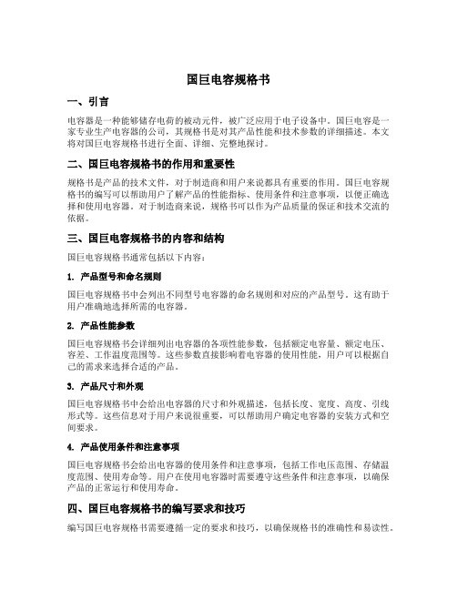
国巨电容规格书一、引言电容器是一种能够储存电荷的被动元件,被广泛应用于电子设备中。
国巨电容是一家专业生产电容器的公司,其规格书是对其产品性能和技术参数的详细描述。
本文将对国巨电容规格书进行全面、详细、完整地探讨。
二、国巨电容规格书的作用和重要性规格书是产品的技术文件,对于制造商和用户来说都具有重要的作用。
国巨电容规格书的编写可以帮助用户了解产品的性能指标、使用条件和注意事项,以便正确选择和使用电容器。
对于制造商来说,规格书可以作为产品质量的保证和技术交流的依据。
三、国巨电容规格书的内容和结构国巨电容规格书通常包括以下内容:1. 产品型号和命名规则国巨电容规格书中会列出不同型号电容器的命名规则和对应的产品型号。
这有助于用户准确地选择所需的电容器。
2. 产品性能参数国巨电容规格书会详细列出电容器的各项性能参数,包括额定电容量、额定电压、容差、工作温度范围等。
这些参数直接影响着电容器的使用性能,用户可以根据自己的需求来选择合适的产品。
3. 产品尺寸和外观国巨电容规格书中会给出电容器的尺寸和外观描述,包括长度、宽度、高度、引线形式等。
这些信息对于用户来说很重要,可以帮助用户确定电容器的安装方式和空间要求。
4. 产品使用条件和注意事项国巨电容规格书会给出电容器的使用条件和注意事项,包括工作电压范围、存储温度范围、使用寿命等。
用户在使用电容器时需要遵守这些条件和注意事项,以确保产品的正常运行和使用寿命。
四、国巨电容规格书的编写要求和技巧编写国巨电容规格书需要遵循一定的要求和技巧,以确保规格书的准确性和易读性。
1. 准确性规格书应准确地描述电容器的性能参数和技术指标,避免出现错误和模糊的表述。
制造商应通过严格的测试和检验来确保规格书的准确性。
2. 清晰性规格书应使用清晰简明的语言,避免使用专业术语和复杂的句子结构。
制造商应考虑到用户的理解能力,尽量以用户为导向来编写规格书。
3. 完整性规格书应包含电容器的所有重要信息,避免遗漏关键参数和注意事项。
贴片独石电容规格表

(0.090)
2.54
(0.100)
2.79
(0.110)
0201~1206 X7R贴片电容选型表
封装尺寸
0201
0402
0603
0805
1206
工作电压
16
16
25
50
10
16
25
50
100
10
16
25
50
100
200
10
16
25
50
100
200
500
电容量
(pF)
100
150
220
A
A
A
C
330
470
680
A
A
A
C
C
C
G
G
G
G
G
G
J
J
J
J
J
J
J
J
J
J
J
J
J
J
J
J
J
J
K
K
K
1000
1500
2200
A
C
C
C
G
G
G
G
G
G
J
J
J
J
J
J
J
J
J
J
J
J
J
J
J
J
J
J
J
J
J
J
J
J
J
J
J
J
J
J
K
M
M
3300
4700
6800
C
贴片电容NPO、X7R、Z5U、Y5V等不同的规格说明

贴片电容贴片电容(单片陶瓷电容器)是目前用量比较大的常用元件,就AVX 公司生产的贴片电容来讲有NPO、X7R、Z5U、Y5V等不同的规格,不同的规格有不同的用途。
下面我们仅就常用的NPO、X7R、Z5U和Y5V来介绍一下它们的性能和应用以及采购中应注意的订货事项以引起大家的注意。
不同的公司对于上述不同性能的电容器可能有不同的命名方法,这里我们引用的是AVX公司的命名方法,其他公司的产品请参照该公司的产品手册。
NPO、X7R、Z5U和Y5V的主要区别是它们的填充介质不同。
在相同的体积下由于填充介质不同所组成的电容器的容量就不同,随之带来的电容器的介质损耗、容量稳定性等也就不同。
所以在使用电容器时应根据电容器在电路中作用不同来选用不同的电容器。
一NPO电容器NPO是一种最常用的具有温度补偿特性的单片陶瓷电容器。
它的填充介质是由铷、钐和一些其它稀有氧化物组成的。
NPO电容器是电容量和介质损耗最稳定的电容器之一。
在温度从-55℃到125℃时容量变化为0±30ppm/℃,电容量随频率的变化小于±0.3ΔC。
NPO电容的漂移或滞后小于±0.05%,相对大于±2%的薄膜电容来说是可以忽略不计的。
其典型的容量相对使用寿命的变化小于±0.1%。
NPO电容器随封装形式不同其电容量和介质损耗随频率变化的特性也不同,大封装尺寸的要比小封装尺寸的频率特性好。
下表给出了NPO电容器可选取的容量范围。
封装DC=50V DC=100V0805 0.5---1000pF 0.5---820pF1206 0.5---1200pF 0.5---1800pF1210 560---5600pF 560---2700pF2225 1000pF---0.033μF 1000pF---0.018μFNPO电容器适合用于振荡器、谐振器的槽路电容,以及高频电路中的耦合电容。
二X7R电容器X7R电容器被称为温度稳定型的陶瓷电容器。
国巨_贴片电容_规格说明-ST_NPOX7R_16V-to-3KV_4
DIMENSION Table 1 For outlines see fig. 3
TYPE L1 (mm) W (mm) T (mm)
0402 0603 0805 1206
1210
1808 1812
1.0 ± 0.15 1.6 ± 0.20 1.6 ± 0.25
0.5 ± 0.15 0.8 ± 0.15 0.8 ± 0.25
force before order.
Surface-Mount Ceramic Multilayer Capacitors
Soft Termination
NPO & X7R
Product specification 3
16V to 3KV
19
CONSTRUCTION
The capacitor consists of a rectangular block of ceramic dielectric in which a number of interleaved metal electrodes are contained. This structure gives rise to a high capacitance per unit volume. The inner electrodes are connected to the two end flexible terminations and finally covered with a layer of plated tin (NiSn). The terminations are lead-free. A cross section of the structure is shown in Fig.1 and Fig.2.
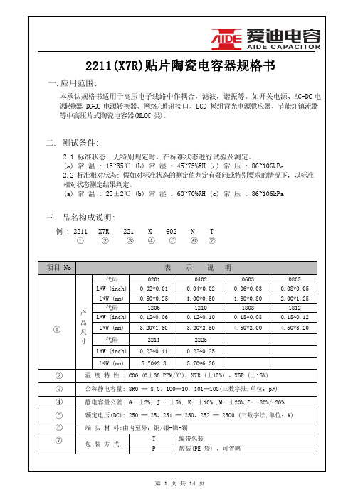
2211(X7R)贴片陶瓷电容器规格书说明书
2 倍额定电压
电压 250V<V<1KV 1.5 倍额定电压
1KV≤V
1.2 倍额定电压
在常温常湿下放置 48±4 小时后再测试.
注:NO3,11,12,13 电容的初值测定:先放在 150℃预热 1 小时,再常温常压放置48 小时测试。
第 5 页 共 14 页
No 项 目
规格
测试方法
使用混合焊锡将电容器焊接在图1 的夹具(玻璃 环氧树脂)上,然后再图 2 所释放向加力. 焊接应 用回流焊进行,避免焊接不均及热冲击等不良 现象.
第 8 页 共 14 页
第 9 页 共 14 页
第 10 页 共 14 页
第 11 页 共 14 页
第 12 页 共 14 页
第 13 页 共 14 页
第 14 页 共 14 页
6
耐电压
无介质被击穿或损伤
Ur=450/500/630V,1.5倍额定电压
(DC)
1KV≤Ur≤2KV,........ 1.2倍额定电压
2KV<Ur,............... 1.1 倍额定电压 升压时间为:1~3S 保压时间为:5S
7
可焊性
■上锡率应大于 95% ■外观无可见损伤
将电容器在 80-120℃预热 10-30 秒,无铅焊料,使用 助焊剂;焊锡温度:245±5℃
测试电压:额定电压测
试时间:60±5 秒测试
5
绝缘电阻
IR≥4*109Ω,C≤25nF
湿度:≤75% 测试
IR*Cr≥100*1012Ω,C>25nF 温度:25±5℃
测试充放电电流:≤50mA
Ur=100V,............. 2.5 倍额定电压
Ur=200V/250V,.... 2.0 倍额定电压
1206 1uF 100V X7R 贴片电容 - 数据表说明书

Contact factory for non-specified capacitance values.
Packaging 2 = 7" Reel 4 = 13" Reel
7 = Bulk Cass.
9 = Bulk
Special Code A = Std. Product
Contact Factory For
PART NUMBER (see page 2 for complete part number explanation)
0805
5
C
103
M
A
T
2
A
Size
Voltage
Dielectric Capacitance Capacitance Failure
Terminations
(L" x W")
4V = 4 6.3V = 6 10V = Z 16V = Y 25V = 3
Dip device in eutectic solder at 260ºC for 60 seconds. Store at room temperature for 24 ± 2 hours before measuring electrical properties.
Meets Initial Values (As Above) No visual defects ≤ ±7.5%
No visual defects ≤ ±12.5%
≤ Initial Value x 2.0 (See Above) ≥ Initial Value x 0.3 (See Above) Meets Initial Values (As Above)
贴片电容容量表

贴片电容容量表X7R贴片电容简述X7R贴片电容属于EIA规定的Class 2类材料的电容。
它的容量相对稳定。
X7R贴片电容特性具有较高的电容量稳定性,在-55℃~125℃工作温度范围内,温度特性为±15%。
层叠独石结构,具有高可靠性。
优良的焊接性和和耐焊性,适用于回流炉和波峰焊。
应用于隔直、耦合、旁路、鉴频等电路中。
X7R贴片电容容量范围厚度与符号对应表0201~1206 X7R贴片电容选型表1210~2225 X7R贴片电容选型表NPO COG 贴片电容容量规格表默认分类 2009-07-15 16:28 阅读354 评论1字号:大大中中小小NPO(COG)贴片电容属于Class 1温度补偿型电容。
它的容量稳定,几乎不随温度、电压、时间的变化而变化。
尤其适用于高频电子电路。
具有最高的电容量稳定性,在-55℃~125℃工作温度范围内,温度特性为:0±30ppm/℃(COG)、0±60ppm/℃(COH)。
层叠独石结构,具有高可靠性。
优良的焊接性和和耐焊性,适用于回流炉和波峰焊。
应用于各种高频电路,如:振荡、计时电路等。
我们把用来制造片式多层瓷介电容(MLCC)的陶瓷叫电容器瓷。
这里所说的瓷介就是用电容器瓷制成的陶瓷介质。
大家知道,陶瓷是一类质硬、性脆的无机烧结体。
就其显微结构而论,大都具有多晶多相结构。
其性能往往决定于其成份和结构。
当配方确定之后,能否达到预期的效果,关键取决于制造陶瓷粉料的工艺。
按其用途可以分为三类:①高频热补偿电容器瓷(UJ、SL);②高频热稳定电容器瓷(NPO);③低频高介电容器瓷(X7R、Y5V、Z5U)。
按温度系数分可以分为两类:①负温度系数电容器瓷(即高频热补偿电容器瓷);②正温度系数电容器瓷(即平时我们常说的COG、X7R、Y5V瓷料)。
按工作频率可以分为三类:低频、高频、微波介质。
高频热补偿、热稳定电容器瓷是专供Ⅰ类瓷介电容器作介质用,其瓷料主要成分是MgTiO3、CaTiO3、SrTiO3和TiO2再加入适量的稀土类氧化物等配制而成。
国巨电容规格书
Conditions
NPO
Requirements
X7R
Y5V
Bending rate 1mm/s, jig. Radius ∆C/C ≤ 1%
∆C/C ≤ 10%
∆C/C ≤ 20%
340mm
260±5°C for 10±0.5s in static ∆C/C ≤ 0.5% or 0.5pF, -5% ≤ ∆C/C ≤ 10% -10% ≤ ∆C/C ≤ 20%
Code 9~11 Material
NPO X7R Z5U Y5V
Code 15~17
Capacitance Value
(2 significant digits + No.
of Zeros)
The 3rd digit:
0=×1
3 = × 103
1 = × 10 4 = × 104
2 = × 102 5 = × 105
CC1812 4.5±0.20 3.2±0.20 0.50 1.80 0.25 0.75 2.20
CC2220 5.7±0.20 5.0±0.20 0.50 1.80 0.25 0.75 2.20
Unit: mm
-3-
YAGEO CORPORATION
Aging Rate
∆C/C (%) 10
Aging Curve
国巨电容国巨贴片电容国巨电阻规格书国巨电阻规格书中文国巨电容型号国巨电子电容厂国巨电子
YAGEO CORPORATION
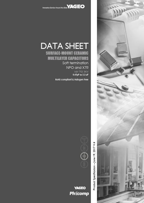
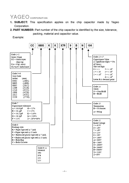
1. SUBJECT: This specification applies on the chip capacitor made by Yageo Corporation.
X7R贴片电容容量范围

J
J
J
J
M
M
P
电容量
(uF)
0.010
0.015
0.022
C
C
C
G
G
G
G
J
J
J
J
J
J
J
J
J
J
J
J
J
J
J
J
J
M
J
J
JHale Waihona Puke JJJJ
J
J
J
J
J
J
J
J
J
M
M
P
0.033
0.047
0.068
G
G
G
G
J
J
J
J
J
J
J
J
J
J
J
J
M
M
J
J
J
J
J
J
J
J
J
J
J
J
J
J
J
M
M
P
0.10
0.15
0.22
G
G
G
G
G
J
J
J
J
J
J
J
J
J
J
J
J
J
J
J
J
J
J
J
J
J
M
P
M
K
K
K
K
K
K
K
P
P
M
M
M
M
M
M
X
X
X
X
X
X
国巨_贴片电容_规格说明4C-Array_16V-to-50V_4

Nov. 10, 2015 V.4
Surface-Mount Ceramic Multilayer Capacitors 4C-Array
NP0/X7R/Y5V
Product specification 5
16 V to 50 V
17
CAPACITANCE RANGE & THICKNESS FOR 4C-ARRAY
Table 2 Temperature characteristic material from NP0
CAPACITANCE
0508 (4 x 0402)
50 V
100V
10 pF 15 pF 18 pF 22 pF 33 pF 39 pF 47 pF 56 pF 68 pF 82 pF 100 pF 120 pF 150 pF 180 pF 220 pF 270 pF 330 pF 390 pF 470 pF 560 pF 680 pF 820 pF 1.0 nF
YAGEO BRAND ordering code GLOBAL PART NUMBER (PREFERRED)
CA XXXX X X XXX X B X XXX
(1) (2) (3) (4) (5) (6) (7)
(1) SIZE – INCH BASED (METRIC) 0508 (1220) 0612 (1632)
capacitors (of the same capacitance value) per array Less than 50% board space of an equivalent discrete component High volumetric efficiency Increased throughout, by time saved in mounting RoHS compliant Halogen Free compliant
国巨排容规格书
(2) TOLERANCE
B = ±0.1 pF C = ±0.25 pF D = ±0.5 pF G = ±2% J = ±5% K = ±10% M = ±20%
(3) PACKING STYLE
R = Paper/PE taping reel; Reel 7 inch K = Blister taping reel; Reel 7 inch P = Paper/PE taping reel; Reel 13 inch F = Blister taping reel; Reel 13 inch
Automotive grade
NP0/X7R
6.3 V to 630 V
CAPACITANCE RANGE & THICKNESS FOR NP0
Table 3 Sizes from 0402 to 0805 0402 0603 CAP.
50 V 0.47 pF 0.56 pF 0.68 pF 0.82 pF 1.0 pF 1.2 pF 1.5 pF 1.8 pF 2.2 pF 2.7 pF 3.3 pF 3.9 pF 4.7 pF 5.6 pF 6.8 pF 8.2 pF 10 pF 12 pF 15 pF 18 pF 22 pF 27 pF 33 pF 39 pF 47 pF 56 pF 68 pF 82 pF 100 pF
85
DATA SHEET
SURFACE MOUNT MULTILAYER CERAMIC CAPACITORS
Automotive grade NP0/X7R
6.3 V TO 630 V
0.47 pF to 1 µF
RoHS compliant & Halogen Free
- 1、下载文档前请自行甄别文档内容的完整性,平台不提供额外的编辑、内容补充、找答案等附加服务。
- 2、"仅部分预览"的文档,不可在线预览部分如存在完整性等问题,可反馈申请退款(可完整预览的文档不适用该条件!)。
- 3、如文档侵犯您的权益,请联系客服反馈,我们会尽快为您处理(人工客服工作时间:9:00-18:30)。
100 pF 150 pF 220 pF 330 pF 470 pF 680 pF 1.0 nF 1.5 nF 2.2 nF 3.3 nF 4.7 nF 6.8 nF 10 nF 15 nF 22 nF 33 nF 47 nF 68 nF 100 nF 150 nF 220 nF 330 nF 470 nF 680 nF 1.0 µF 2.2 µF 4.7 µF 10 µF 22 µF 47 µF
May. 26, 2015 V.12
Product specification
4
19
Surface-Mount Ceramic Multilayer Capacitors
General Purpose & High Cap.
X7R
6.3 V to 50 V
CAPACITANCE RANGE & THICKNESS FOR X7R
terminations
electrodes
MLB457
ceramic material
Fig. 1 Surface mounted multilayer ceramic capacitor construction
DIMENSION
Table 1 For outlines see fig. 2 TYPE 0201 0402 0603 0805 1206 1210 1812
0.85±0.1
1.25±0.2 0.8±0.15 1.25±0.2 1.25±0.2 1.25±0.2 1.25±0.2
1. Values in shaded cells indicate thickness class in mm 2. Capacitance value of non E-6 series is on request 3. For product with 5% tolerance, please contact local sales force before ordering
YAGEO BRAND ordering code
GLOBAL PART NUMBER (PREFERRED )
CC
XXXX X X
X7R
X
BB
XXX
(1)
(2) (3)
(4)
(5)
(1) SIZE – INCH BASED (METRIC)
0201 (0603) 0402 (1005) 0603 (1608) 0805 (2012) 1206 (3216) 1210 (3225) 1812 (4532)
0.5±0.05
0.5±0.05
0.5±0.05
0.5±0.05
0.5±0.05
1. Values in shaded cells indicate thickness class in mm 2. Capacitance value of non E-6 series is on request 3. For product with 5% tolerance, please contact local sales force before ordering
DATA SHEET
SURFACE-MOUNT CERAMIC MULTILAYER CAPACITORS
General Purpose & High Capacitance Class 2, X7R
6.3 V TO 50 V
100 pF to 22 µF
RoHS compliant & Halogen Free
Fig. 2 Surface mounted multilayer ceramic capacitor dimension
1. Dimension for size 0603, C < 2.2 µF; 0805 to 1812, C ≤ 100nF 2. Dimension for size 0603, C = 1µF; 50V; 0805 to 1812, C > 100 nF
SCOPE This specification describes X7R series chip capacitors with leadfree terminations. APPLICATIONS PCs, Hard disk, Game PCs DVDs, Video cameras Mobile phones Data processing FEATURES Supplied in tape on reel Nickel-barrier end termination RoHS compliant Halogen Free compliant
May. 26, 2015 V.12
Product specification
6
19
Surface-Mount Ceramic Multilayer Capacitors
General Purpose & High Cap.
X7R
6.3 V to 50 V
CAPACITANCE RANGE & THICKNESS FOR X7R
Table 3 Sizes from 0603 to 0805 0603 CAP.
6.3 V 100 pF 150 pF 220 pF 330 pF 470 pF 680 pF 1.0 nF 1.5 nF 2.2 nF 3.3 nF 4.7 nF 6.8 nF 10 nF 15 nF 22 nF 33 nF 47 nF 68 nF 100 nF 150 nF 220 nF 330 nF 470 nF 680 nF 1.0 µF 2.2 µF 4.7 µF 10 µF 22 µF
Product Specification – May 26, 2015 V.12
Product specification
2
19
Surface-Mount Ceramic Multilayer Capacitors
General Purpose & High Cap.
X7R
6.3 V to 50 V
(2) TOLERANCE
J = ±5% (1) K = ±10% M = ±20%
(3) PACKING STYLE
R = Paper/PE taping reel; Reel 7 inch K = Blister taping reel; Reel 7 inch P = Paper/PE taping reel; Reel 13 inch F = Blister taping reel; Reel 13 inch C = Bulk case
NOTE
0402
16 V 25 V 50 V 6.3 V 10 V 16 V 25 V 50 V
10 V
0.3±0.03
0.3±0.03
0.3±0.03
0.3±0.03
0.3±0.03
0.5±0.05 0.5±0.05 0.5±0.05 0.5±0.05 0.5±0.05
0.5±0.05
0.5±0.05
ORDERING INFORMATION - GLOBAL PART NUMBER, PHYCOMP CTC & 12NC All part numbers are identified by the series, size, tolerance, TC material, packing style, voltage, process code, termination and capacitance value.
(4) RATED VOLTAGE
5 = 6.3 V 6 = 10 V 7 = 16 V 8 = 25 V 9 = 50 V
(5) CAPACITANCE VALUE
2 significant digits+number of zeros The 3rd digit signifies the multiplying factor, and letter R is decimal point Example: 103 = 10 x 103 = 10,000 pF = 10 nF
NOTE
L1 (mm)
0.6 ±0.03 1.0 ±0.05 1.6 ±0.10
(1)
W (mm)
0.3 ±0.03 0.5 ±0.05 0.8 ±0.10
(1)
T (MM)
L2 / L3 (mm) min. max.
0.10 0.15 0.20 0.25 0.25 0.25 0.25 0.20 0.30 0.60 0.75 0.75 0.75 0.75
(2)
0.8 ±0.15 (2) 1.25 ±0.10 (1) 1.25 ±0.20 (2) 1.6 ±0.15 (1) 1.6 ±0.20 (2) 2.5 ±0.20 (1) 2.5 ±0.30 (2) 3.2 ±0.20 (1) 3.2 ±0.40 (2) Refer to table 2 to 4
May. 26, 2015 V.12
Product specification
5
19
Surface-Mount Ceramic Multilayer Capacitors
General Purpose & High Cap.
X7R
6.3 V to 50 V
CAPACITANCE RANGE & THICKNESS FOR X7R
NOTE
0805
16 V 25 V 50 V 6.3 V 10 V 16 V 25 V 50 V
10 V
0.6±0.1
0.6±0.1
0.6±0.1
