Speed line操作流程
.Net 驰骋即时通讯系统CCIM使用手册簿

驰骋即时通讯系统CCIM 1.0使用手册驰骋信息技术2012年4月目录1概要说明 (5)1.1版本说明 (5)1.2采用的开发技术 (5)1.3服务器端要求 (5)1.4客户端要求 (6)1.5性能指标 (6)1.6 CCIM与CC其它产品之间的关系 (6)2安装与数据维护 (7)2.1安装GPM (7)2.2系统安装 (7)2.2.0执行创建CCIM表脚本 (7)2.2.1服务器 (8)2.2.2客户端 (9)2.3与ccflow集成 (10)3功能使用说明 (10)3.1 CCIM功能概览 (10)3.1.1 控制面板 (10)3.1.2图标与说明 (11)3.2 CCIM基本功能操作展示 (12)3.2.1登录 (12)3.2.2文字聊天 (12)3.2.3发送文件 (13)3.2.4视频对话 (14)3.2.5对话记录/信息管理器 (15)3.2.6群发消息 (16)3.2.7创建组 (17)3.2.8我的工作 (17)3.2.9我的状态 (18)3.2.10签名 (18)3.2.11设置 (19)3.2.12网络硬盘 (19)3.2.13样式 (20)3.2.14色彩 (20)3.2.15最近联系人 (21)3.2.16关于 (21)3.2.17自动更新/升级 (22)4 CCIM的二次开发 (22)1概要说明1.1版本说明版本分类:CCIM企业版是应用于企业或者机关事业单位部的系统具有耗费资源少,方便维护,方便集成等。
CCIM与开源的驰骋工作流程引擎是高度集成的但是也可以独立使用。
说明:CCIM 对于200个以下是免费的,任何个人与单位不得反编译。
技术论坛:/showforum-2.aspx1.2采用的开发技术采用.net framework 2.0,C#,数据库采用SQL Server 2005或以上,暂时不支持oralce 与mysql用户。
CCIM不仅可以使用于企业部局域网,VPN,还能应用在外网上,可以穿透NAT。
道亨三维可视化跳线计算系统操作说明

三维可视化跳线计算系统操作说明目录第一章软件概述 (1)1.1 功能简介 (1)1.2 运行环境 (1)1.3 注意事项 (1)第二章操作流程 (2)第三章操作步骤(单塔) (4)3.1启动道亨JW三维可视化跳线计算程序(单塔) (4)3.2导入塔结构 (4)3.3输入气象条件 (7)3.4输入导线信息 (9)3.5输入线路参数 (14)3.6计算并查看结果信息 (15)第四章操作步骤(批量计算) (23)4.1启动道亨JW三维可视化跳线计算程序(批量计算) (23)4.2导入TA或CSV文件 (23)4.3批量计算铁塔跳线 (30)第五章优选示例 (32)5.1 已知条件输入 (32)5.1.1 气象条件 (32)5.1.2 导线参数 (33)5.1.3 导线分裂情况 (33)5.1.4 串信息 (34)5.1.5 计算参数 (35)5.1.6 优选 (36)5.2 计算结果 (36)第六章验算示例 (39)6.1 已知条件 (39)6.1.1 气象条件 (39)6.1.2 导线参数 (39)6.1.3 导线分裂情况 (40)6.1.4 串信息 (41)6.1.5 计算参数 (42)6.1.6 验算 (42)6.2 验算结果 (43)附录A 快速建塔 (45)第一章软件概述1.1 功能简介《道亨JW三维可视化跳线计算程序》本程序创新性地采用三维空间数学模型,可以对任意跳线情况进行准确计算。
程序能够计算单回路和多回路、耐张塔、终端塔等跳线长度的软件。
本系统适用于任意电压等级、任意塔型、任意位置跳线长度的计算。
支持多种跳线方式、多个跳线的计算。
支持验算跳线长度或自动优选跳线长度,能够批量计算多个铁塔跳线,能出工程需要的跳线长度弧垂表,并能导出AutoCAD格式的文件。
1.2 运行环境操作系统:Windows 2000 / XP / Vista/Win7硬件:通用流行配置计算机CPU:1GHz 以上内存:256 MB 以上硬盘:500MB以上空闲磁盘空间显示器:1024×768 分辨率以上1.3 注意事项系统运行前请将加密锁接在计算机的并行口(连接打印机的25针接口)或者USB接口上;请特别注意:不论单机锁还是网络锁,一台电脑同时只能使用一个锁,也就是只能插一个锁,后插入的锁或者网络锁是无法使用的。
Speed2000中文手册

c.当 A 线段 a1 端点与 b2 点重合时,在重合点出现较大的、闪烁的十字形光标,此时松开“Ctrl”键; 两线已经和成一条线了
d.检查结合:使用移动功能,任意选择一个端点进行移动操作,A 线和 B 线现在是一起移动了
注意:在 SPEED 2000 中术语“Package”,可以是一个 IC 的封装,也可以是指印刷电路板。任何不是属 于电路元件的东西都认为是 Package。
1
第一章
SIGRITY SpeedXP 实用手册参考
本章试图通过一个例子的分析、操作使用户对 Speed 2000 的使用、性能有一个较为直观的理解。建 议用户首先根据此例一步步的进行操作,从中领会、理解、掌握 Speed 2000 的性能以及使用方法。
2.2.8 设置网格
当为一个微分等式求解的时候,通常我们会用数字网格(numerical mesh)将一个连续的问题空间进 行分割。这样一来,我们的数字化计算技术只需要考虑分割后离散的数据点上的变量,而不是整个连续的 问题空间了。在 speed2000 中,我们使用统一的矩形网格分割金属板上连续的电压和电流变量。举个例子, 在计算中,从逻辑上讲,每个过孔(via)应该对应与它最邻近的网格点,但是,如果网格比较粗糙(格点 比较大),那么有可能出现两个或者两个以上的路由对应同一个网格点。speed2000 目前将这种情况归为 “离散错误”。用下面的步骤可以检查和解决“离散错误”。
6
SIGRITY SpeedXP 实用手册参考
是说该层上所有的导线颜色都以红色显示,点击 OK 后退出。
双击该层
出现该层的参数设置窗口
FF现场总线使用使用说明

FF现场总线使用说明书1 引言FF是基于WorldFip North American (FIP)和InterOperable System Project(ISP)的共同利益,而在1994年合并而成的。
1995年,WorldFip欧洲部分也加入了FF。
FF总线由低速(H1)和高速(HSE,High Speed Ethernet)两部分组成。
低速H1部分将ISO/OSI七层参考模型结构简化为物理层、数据链路层、应用层,再加上用户层,形成四层结构。
同时,为了适应以太网技术的发展,现场总线基金会放弃了其原来规划的H2高速总线标准,并于2000年3月29日公布了基于Ethernet的高速总线技术规范(HSE1.0版)。
HSE充分利用低成本的以太网技术,以100M bit/s到1G bit/s或更高的速度运行,它主要用于制造业(离散控制)自动化以及逻辑控制、批处理和高级控制等高速的现场总线网段的互连。
本手册是组态实验室现场总线系统组态的使用说明书,内容包括了使用组态软件,组态一个典型的DEMO现场总线的详细过程。
2 实验室包含的现场总线设备本现场总线实验室是一个典型现场总线控制系统的配置,设备清单如表1所示:网关、网桥、现场总线接口和端子块等部件构成。
现场总线网络上连接的现场总线设备有两种:一种是总线供电式现场设备,它需要从总线上获取工作电源,总线供电电源就是为这种设备准备的;另一种是单独供电的现场设备,它不需要从总线上获取其工作电源。
常用的现场总线设备有温度变送器、压力(差压)变送器、流量变送器、液位变送器和调节阀等。
这些现场设备不仅有信号变换功能,而且还有组态运算及控制功能。
终端器是连接在总线末端或末端附近的阻抗匹配元件。
每个总线段上需要两个,而且只能有两个终端器。
终端器采用反射波原理使信号变形最小,它所起到的作用是保护信号,使它少受衰减与畸变。
有时,将终端器电路内置在电源、安全栅、PC接口卡和端子排内。
飞创交易平台X-Speed使用说明

飞创交易平台X-Speed使用说明©大连飞创信息技术有限公司版权所有文件状态:[ √ ] 草稿[ ] 正式发布[ ] 正在修改文件标识:『飞创交易平台X-Speed使用说明』当前版本:V 1.0.0.2作者:刘世伟完成日期:2012年3月16日版本日期AMD 修订者说明V 1.0.0.2 2012年9月28日 A 冷雪冬增加3.3.1.4V1.0.0.2 2012年9月28日M 冷雪冬修改4.2.3.4V1.0.0.2 2012 年11月6日 A 冷雪冬 3.6.2.1增加了保证金批量委托介绍一.总述飞创交易平台X-Speed是一款基于内存数据库的、三层架构的、面向期货、期权业务的综合交易平台。
整套平台由飞创公司自主研发,其主要由内存数据库、消息中间件、交易中间件、交易监控客户端、柜台终端、交易终端共六部分组成。
其特点主要体现在:交易速度快、交易容量大、运维部署简单、易于使用。
是为行业专业炒手或机构客户量身定制的轻量级快速交易系统。
系统整体架构如图(1):图(1)二.服务器&监控客户端使用说明交易服务器是飞创交易平台的核心模块,其主要负责接收交易终端请求信息、实时交易逻辑处理、计算客户实时盈亏、可用资金、监控实时风的功能,以及连接四家交易所交易前置,进行委托申报、成交回报处理等场上交易业务。
飞创交易平台,各服务程序是以插件的形式集中挂载在交易监控终端上的,由交易终端统一进行管理。
由于例如服务启停、服务监控、服务配置等相关操作。
图(2)2.1服务器插件介绍飞创交易平台服务主要由交易平台消息中心服务(FUMCenter)、交易平台内存交易服务(FU_FO、FUTrade)、交易平台大连、中金、上期、郑州交易所报盘服务(DLComm、ZJComm、SQComm、ZZComm)组成。
其中,消息中心服务用于集中处理交易平台内部消息订阅、消息请求等操作;内存交易服务(FUTrade)用于集中处理场上交易逻辑,并作为服务器端,向外界提供操作接口;四家交易所报盘程序,则分别用于处理交易所委托申报、委托确认、成交回报等操作。
金万维异速联使用说明书
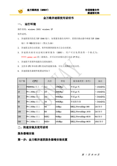
金万维异速联使用说明书一、运行环境操作系统:windows 2003/ windows XP软件说明:1.异速联使用的是TCP 5366端口,如果服务器在内网中,需要在路由器中映射TCP 5366端口和 WEB服务端口(默认为80)2.异速联支持自动更新,软件检测到新版本后会自动更新。
3.异速联内嵌有动态域名解析服务(DDNS),用户可以免费获得一个格式为:*****的二级域名,并可以对该域名进行动态IP绑定。
异速联不需要终端服务及授权操作。
和双核CPU的高性能服务器,可以大规模的并发应用。
异速联服务器硬件配置说明如下用户数CPU 内存带宽服务器类型(参考)备注5PIII600hz以上512100KBps普通pc机<1MADSL 10P4-1.8Ghz以上1G200KBps普通pc机<1MADSL 20P4-2.0Ghz以上2G400KBps普通pc机<2MADSL 30P4-2.6Ghz以上2G400KBps普通服务器<2MADSL 50P4-2.8Ghz以上4G1MBps DELL PowerEdge 8601M独享100P4-2.8Ghz以上8G2MBps DELL PowerEdge 19502M独享200P4-2.8Ghz以上8GX24MBps DELL PowerEdge 68504M独享500P4-2.8Ghz以上8GX410MBps DELL PowerEdge 665010M独享二、快速安装及使用说明服务器端安装第一步:金万维异速联服务器端安装设置如果您服务器所在网络没有固定IP,您可以在安装时选择使用动态域名解析选项。
点击下一步本软件默认“在当前系统用户下安装此快捷方式”,如果本机系统的所有用户都需要创建快捷方式,您可以选择“在所有系统用户下安装此快捷方式”。
点击下一步进行安装即可。
安装过程中会进入服务器web server的端口设置。
一般默认为80端口。
点击检测如果服务器上的80端口被其他程序占用,软件会自动检测默认端口是否被占用,如被占用可以更换为如:81,82,83等。
SPEEDEDIT

每个SpeedEDIT的功能都是 多个思路的
自动向已知的空白素材校正。
在低/中/高色带分别校正颜色
件夹拖到时间线上,他就可以 滑动并播放了。避免了你建立 节目时转换或生成素材所浪费 的时间。 无论你是为向Ju mbotron, HD,DVD输出而编辑,还是 为播放而编辑,你可以准确的 提供用户要求的内容。 编辑你的任意素材,焦点放在 速率和时间线。当完成时,你 可以以需要的任意分辨率生 成。 从采集,加字幕到输出,整个 工作流程支持方形的电视纵横 比或宽银幕。 无需考虑素材的格式,文件类 型或文件扩展名,把你的全部 注意里放在建立节目上,避免 因为混入不同的素材而被处 罚。 所有的摄象机和倒带装置现在 都有FireWire,这是最简单的 摄取或送回视频的方法。 一次完成一个动作或是颜色校 正。然后,点击2次,唤回它 应用给一个或多个节目中的素 材上。 CG Post可以以任意纵横比和 分辨率动画字幕。接近200个 预设页面可以从一个起点进行 快速的设置。 把踏板推到金属(Push the pedal to the metal。)。 SpeedEDIT利用新的双核心 和多处理器系统,榨取你硬件 的最大性能。 有时候,当拍摄太快时,你可 能直到后来检查时,才发现从 完整的太阳区到阴影地方影响 了你的拍摄。SpeedEDIT可以 让你向你的视频做微妙而主要 的暖/冷(warm/cool)的操作。 阴影,中间部分和加亮区的不 同颜色和gamma控制成为颜 色校正的标准。SpeedEDIT让 你可以对微妙的颜色校正和改 变进行实时操作,在不同色带
使用饱和度或色度修改颜色。 再做3次,你就可以微调画面 里的任何东西了。
情节图板和时间线以同样的数 情节图板是建立故事,制作广
Speed line操作流程

進板 托盤頂起
托盤放下
進板停止
第四步 PCB 的定位及頂針(Tooling pin)的安放
前擋柱Y方向的移動
設置應用鍵
前擋柱
第五步 停板前擋柱裝置的設置
( 在PCB右下角有缺角的情況下使用此設置)
第六步 建立印刷參數數據(Edit Print profile)
印刷參數修改
1. • • • • • • • • • • • • • • Standard 1.print Independent profiles: ( 單獨程式 ) a.Forward ( 向前印時 ) b.Backward ( 向後印時 ) 可分別輸入前後刮刀在印刷時,印刷速度及刮刀壓力,若無選擇則前後刮 刀使用相同的印刷參數。 Speed ( 印刷速度 ) ( 1-200mm ) Pressures ( 刮刀壓力 ) ( 0-20kg ) 2.Stroke ( 印刷行程 ) Start ( 起始點 ) ( -20-514mm ) Distance ( 印刷行程 ) ( 50-514mm ) Squeegee forward offset ( 刮刀前進補償值 ) ( 0-50mm ) 3.Snap-off ( 脫離速度和距離設定 ) Speed ( 脫離速度 ) ( 0.2-10mm/s ) Distance ( 脫離距離 ) ( 0-1mm )
Speed line
(MPM Accuflex)
全自動印刷機操作流程
開機步驟
1. 將機器後端主電源保險開關(20A)開至ON(下頁有圖示), 檢查氣壓 供應必需在5BAR-24lites/minute. 機器前端主開關(下頁有圖示)旋轉至1(ON)位置,機器開始讀取控 制程式 當螢幕出現畫面時,輸入開機名字及密碼後點選OK鍵。輸入方式 由鍵盤輸入 之後螢幕出現開機畫面後,請旋松紅色E-stop開關和按下前方綠色 System Power開關後,請點選OK鍵(下頁有圖示) 機器開始進入主畫面,並載入機器基本設定及機器各項回歸原點, 之後可於螢幕上看見相關畫面,即表示開機完畢。
speedline omni 7中文操作说明书

一、开启1. 确认连线正确和设备正常后(无短路,各传动未卡住)开启设备电源图1二、控制界面2)图2如启运后控制程序未启动或关闭程序后再打开,请双击桌面上的快捷图标,即进入主控界面 1. 1菜单栏菜单栏内容如下,单击相应的菜单,会出现次级菜单,点击相应选项,会打开相应的控制窗体。
(图3)设置 记录 配方 屏幕 帮助(即参数设置方案) (图3)温区图形显示灰色时表示关闭过板数量1.1.1”Setup”主菜单下主要为设备运行的所有参数的设置,其下级菜单如下:(图4)!注意:“Setup”菜单下的“Configure”菜单内的所有选项非专业人员不得擅自更改,否则会造成不可预料的故障和事故!图4配置菜单项“configure”主要为设备的所有参数校准菜单项“Calibrate”主要为设备参数校准备份数据菜单项”Backup Data”为备份现有设置好的参数,出现以下窗口,插入软盘到软驱后,点击OK后备份到软盘。
(如图5)图5恢复数据菜单项”Restore Data”为恢复已备份参数,点击后出现以下窗口,把备分软盘插入软驱后点击OK将恢复存在软盘上的数据。
1.1.2单击”Configure”菜单后会出现它的下级菜单1.1.2.1单击“Options”菜单项会出现下级菜单(图6)图61.1.2.2单击传运菜单栏”Conveyor”即进入传动参数设置界面选项被选择时,过板方向为右至左复选框被选择时,设备为双导轨机型图7其“General“选项有两个复选框,选择后实现传动的非标准选项(根据设备情况)。
图8“Conveyor#1”为传运导轨1选项,其界面功能为“Conveyor Type”为运输方式,选择”Belt”时设备为网带,“Rail“时为导轨传动“Rail Drive Spocket“为传运齿数,有两种选择”18-tooth”、”19-tooth” “Machine interface”为设备控制界面选项“Rail Options”导轨传动选项:“Rail Heaters”为导轨加热选项“Motorized Width”为导轨为机动调宽选项“Auto Width Adujst”为导轨宽度自动调整“Widths Befor Home”为导轨归零时的最小宽度以上所有选项需配合设备硬件功能,一般情况下设置后不用更改。
自动点胶机操作说明书
Operating Manual
E type Ver C Page 2
Contents 目錄:
1. 使用前注意事項.................................................................................................................................... 6 2. 隨機附件................................................................................................................................................ 7 3. 機器按鍵及接頭位置介紹................................................................................................................... 8
7.1. 按鍵使用 Key Selection............................................................................................................................ 19 7.2. 按鍵定義 Key Assignments..................................................................................................................... 20 7.3. 功能選項 Menu Navigation..................................................................................................................... 21 7.4. 功能總表 Function Summary..................................................................................................................... 21
FANUC CNC 系统与计算机之间PMC 的传输

CNC系统与计算机之间PMC的传输现在的PMC由于功能较以往的强大,其传输方法也与原来不同,主要有三种方法。
1.使用传统的RS-232口的传输1)在目前的CNC系统的PMC传输画面上大家看不到以往的HOST健,也找不到专门的SPEED 画面设置RS-232口的传输参数。
现在传输主要通过按[PMC]à[MONIT]à[ONLINE]健后,在出现的下面画面中进行设定。
2)计算机侧的设定:在FANUC LADDER Ⅲ[Communication ],出现如下 图所示的画面:点击Connect 后,计算机与CNC 建立通讯连接,出现下面的画面。
建立好连接后,关闭上面的画面。
然后,如下图所示,点击[TOOL]下的[Load from PMC]。
3)点击[Load from PMC]后进入如下画面。
在此画面上可以选择传输Ladder程序或PMC Parameter(PMC参数) 。
点击[Browse]选择存放的路径。
按照提示的步骤一步步向下。
点击[Finish],从系统向计算机传输PMC。
左图显示传输进程。
反编译。
4)在计算机上显示的梯形图可以进行编辑、修改。
若要修改,须点击[ON Line] 使通讯处于脱线[OFF Line]状态,然后修改。
修改后的梯形图不能直接传回给CNC,CNC要求把图形格式的PMC程序转变为二进制数据格式,因此必须将该梯形图进行编译(Compile)。
为此,须再次点击[ON Line] 与系统建立通讯,系统自动提示编译源程序。
编译后,根据提示[Store to PMC],把编辑好的、并经过编译的PMC(二进制数据格式)传入到CNC系统中。
注意:把PMC传输到CNC系统后,应注意保存,即应把PMC写入到系统的F-ROM中。
其写入操作(在CNC系统上)如下图所示。
若不进行此项操作,CNC断电后PMC程序即丢失。
RS-232-C进行PMC的传输后,应在CNC系统上操作,将RS-232-C口置于[NOT状态(见下图),以关断系统的在线编辑(也可按下[EMG ST]键)。
即时通操作说明
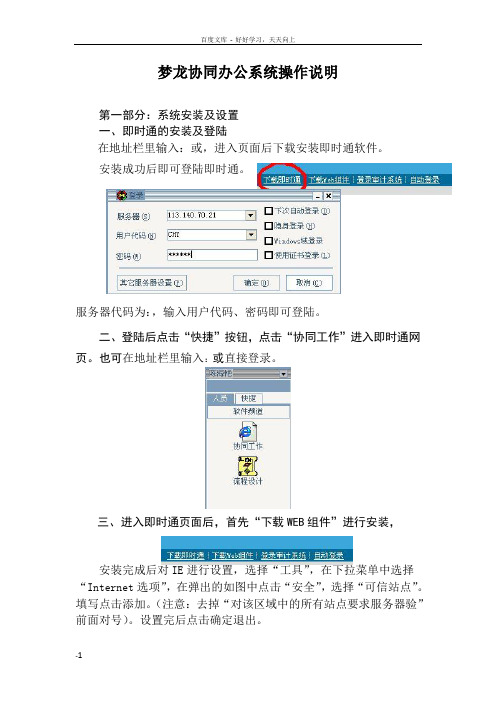
梦龙协同办公系统操作说明第一部分:系统安装及设置一、即时通的安装及登陆在地址栏里输入:或,进入页面后下载安装即时通软件。
安装成功后即可登陆即时通。
服务器代码为:,输入用户代码、密码即可登陆。
二、登陆后点击“快捷”按钮,点击“协同工作”进入即时通网页。
也可在地址栏里输入:或直接登录。
三、进入即时通页面后,首先“下载WEB组件”进行安装,安装完成后对IE进行设置,选择“工具”,在下拉菜单中选择“Internet选项”,在弹出的如图中点击“安全”,选择“可信站点”。
填写点击添加。
(注意:去掉“对该区域中的所有站点要求服务器验”前面对号)。
设置完后点击确定退出。
四、初次登陆后要及时更改自己的密码,用户密码要求至少三个月更改一次,如不及时更改,系统管理员将强制性对密码进行更改(注:用户名是个人姓名的全拼,初始密码:321123)。
各项目部文书管理账户请同公司办联系,电话:五、各项目文书管理员每月25号之前向公司办上报各项目在职人员,以便公司对人员信息及时进行更新。
项目人员发生变化,应及时通报公司办。
(具体填报信息见附表)六、各项目文书管理人员每天应至少登录办公系统两次以上,及时对文件进行处理。
第二部分:平台操作说明一、我的桌面1.通讯录(1)个人通讯录:用于记录私人通讯录。
(2)内部通讯录:可查询机关各部门或各单位人员电话。
2.内部邮件向公司某个人发送邮箱或一对一传送文件时,可通过即时通或内部邮件发送。
二、信息发布:1. 公告(机关各部门使用)用于发布需要广为人知的一般性通知(不需要领导签发的)。
操作步骤:点击“添加内容”按钮→依次填全发文信息→上传文件→发布。
其中“来源”一栏应填写“××部(室)”。
2.文件用于查阅公司已发布的“行政文件”、“行政网络电报”、“党委文件”、“董事会文件”、“工会文件”、“纪委文件”、“团委文件”及公司“三标体系”等文件。
3.综合信息用于查阅公司发布的“项目综合通报”、“要情通报”、“计统、工程简报”、“物资简报”、“设备信息”、“法律园地”、“廉政园地”和“设备使用费”等内容。
Speedlane900-操作手册新版分解

SPEEDLANE 900操作手册1 Speedlane900操作手册目录1 前言 (3)2 介绍 (4)2.1 原理和设计 (4)3 不同版本 (7)3.1 标准装置 (7)3.2 加高装置 (7)3.3 加宽装置 (8)3.4 加长装置 (8)3.5 多通道S PEEDLANES ( 可选) (9)3.6 激活选项 (9)3.7 显示选项 (10)4 运行原理 (11)4.1 介绍 (11)4.2 标准运行 (11)4.3 方向类型 (12)4.4 读卡器控制 (12)4.5 安全 (13)4.6 反馈信号 (15)4.7 其它报警 (16)4.8 控制面板( 可选) (17)4.9 调节选择菜单 (19)5 维护 (20)6 故障检修 (21)7 零部件 (23)8 规格和尺寸 (24)版权此手册由宝盾公司编写和出版。
它仅供Speedlane 用户和宝盾公司经销商使用。
宝盾公司版权所有。
本手册包含的所有资料属于宝盾公司财产。
未经宝盾公司授权不得将资料转发给第三方。
Speedlane900操作手册 21 前言阅读本手册在首次使用Speedlane 前,请认真阅读本操作手册。
不明确信息本操作手册为宝盾公司精心编写,然而如果某些部分表达不清或出现错误,请与宝盾公司或您的供应商联系。
他将为您解释如何操作Speedlane。
手册的使用者只有熟悉本手册所使用语言的人员才可以执行维护工作。
本手册提供给Speedlane的用户,并提供以下信息:•操作Speedlane•维护工作•故障检修标志您会在本操作手册中遇到一些标志。
这些标志的包含的意思如下:警告!可能带来人身伤害或生命危险。
注意!材料可能被损坏或影响门的运行。
使用的缩写⏹MCB 微处理器电路板⏹UPS 不间断电源⏹F I变频器⏹N.O. 常开⏹N.C. 常闭⏹L E D 发光二极管CE 标记, 铭牌和玻璃贴CE标识位于主支架内,去掉顶盖后可以直接看到。
心电图机使用说明
心电图机使用说明1.电源开关置于“ON”。
2.电源开关置于“AC(交流),’,此时“LINE”“TBST”“PA PER SPEED(25mm/s)”“SENSITIVITY(l)”“STOP”,晶体灯发出亮光。
3.调节基线控制旅钮应能改变描笔的位置,使之停在纪录纸中央附近。
4.按动“CHECK”键,此时“STOp”灯灭,“CHECK”灯亮。
5.按动定标键“lmV”,使描笔随着定标键的按动而作相应的摆动。
6.按“START”,此时“CHECK”灯灭,“START”灯亮,记录纸按25mm/sec速度走动。
7.继续按动定标键,在走动的纪录纸上可看到一清晰的定标方波,其振幅应是10mm。
8.按动“LEADSELECTOR”键,使之由“TEST”向“I”导“Ⅱ”联转换。
9.在心电图纸上得到一段清晰的纪录后,可继续按动“LEAD SELECTOR”键,使之由“I”导联向“Ⅱ”导联转换,以此类推,可重复上述操作,完成12个导联的心电图纪录。
10.仪器使用完毕,切断电源,做好清洁工作。
并做好仪器使用登记。
电图机是记录人体心电图的专用仪器,心电图机的有严格的国际标准,心电图机由专业厂家设计、制造。
人体心电图机种类繁多,从记录笔数分有单道心电图机和多道心电图机;从用途分有普通心电图机、心电监护仪和动态心电图机。
有些心电图机带有示波屏,也称心电示波器。
人体心电图机也可用来记录动物的心电图,其记录的心电图质量一般优于普通记录仪。
(一)心电图机基本结构心电图机基本结构包括:1.记录纸盒装记录纸卷。
2.笔位置控制旋调节记录笔基线。
3.导联选择按钮或开关选择记录导联。
4.50Hz滤波按钮或开关滤去50Hz干扰5.灵敏度按钮或开关选择记录灵敏度,灵敏度有1/2、1和2三档。
6.走纸速度按钮或开关走纸速度选择,走纸速度有25mm/min和50mm/min二档。
7.1mV定标按钮或开关用于灵敏度校正,按下1mV定标电压,记录幅度为10mm。
FF现场总线使用说明书

FF现场总线使用说明书1 引言FF是基于WorldFip North American (FIP)和InterOperable System Project(ISP)的共同利益,而在1994年合并而成的。
1995年,WorldFip欧洲部分也加入了FF。
FF总线由低速(H1)和高速(HSE,High Speed Ethernet)两部分组成。
低速H1部分将ISO/OSI七层参考模型结构简化为物理层、数据链路层、应用层,再加上用户层,形成四层结构。
同时,为了适应以太网技术的发展,现场总线基金会放弃了其原来规划的H2高速总线标准,并于2000年3月29日公布了基于Ethernet的高速总线技术规范(HSE1.0版)。
HSE充分利用低成本的以太网技术,以100M bit/s到1G bit/s或更高的速度运行,它主要用于制造业(离散控制)自动化以及逻辑控制、批处理和高级控制等高速的现场总线网段的互连。
本手册是组态实验室现场总线系统组态的使用说明书,内容包括了使用组态软件,组态一个典型的DEMO现场总线的详细过程。
2 实验室包含的现场总线设备本现场总线实验室是一个典型现场总线控制系统的配置,设备清单如表1所示:网关、网桥、现场总线接口和端子块等部件构成。
现场总线网络上连接的现场总线设备有两种:一种是总线供电式现场设备,它需要从总线上获取工作电源,总线供电电源就是为这种设备准备的;另一种是单独供电的现场设备,它不需要从总线上获取其工作电源。
常用的现场总线设备有温度变送器、压力(差压)变送器、流量变送器、液位变送器和调节阀等。
这些现场设备不仅有信号变换功能,而且还有组态运算及控制功能。
终端器是连接在总线末端或末端附近的阻抗匹配元件。
每个总线段上需要两个,而且只能有两个终端器。
终端器采用反射波原理使信号变形最小,它所起到的作用是保护信号,使它少受衰减与畸变。
有时,将终端器电路内置在电源、安全栅、PC接口卡和端子排内。
Syteline系统操作手册

SytelineERP系统操作手册许继信息中心ERP组编写目录目录 (2)前言 (3)S YTE L INE系统常用快捷图标解释 (4)S YTE L INE系统常用快捷键一览表 (5)第一章主要程序操作 (6)第一节采购管理 (6)第二节存货管理 (14)第三节生产管理 (21)第四节销售管理 (26)第二章图解说明手册 (32)第一节采购管理 (32)第二节采购单计划 (33)第三节BOM业务流程 (34)第四节生产管理 (37)第五节参数设置 (42)第六节供应商维护 (44)第七节请购单操作图解说明 (45)第八节请购单、采购单相关报表 (47)第九节采购管理主要步骤 (49)第十节数据维护的工作流程管理 (50)第三章ERP系统编码规则 (52)第一节物料编码规则 (52)第二节打印机设置 (53)第三节解决翻译软件造成的问题 (60)第四节打印到一个文件 (60)第五节请购单与采购单信息互通 (60)前言第四版本操作手册是由信息中心编制,包括了SyteLine系统主要程序的操作步骤,图解流程说明,编码规则,操作技巧等四大方面的内容。
此手册针对性强,是切合实际的指导性手册。
在实际应用中,也许有些程序说明在你自己的菜单中看不到,这是因为岗位权限的限止造成的,是综合电源公司所有岗位程序编写的,请针对自已的岗位和权限进行阅读。
注:本操作手册图形是截取亿万物流公司数据库,有一些说明是专指指亿万物流公司,诸如EWWL是指亿万物流默认仓库,电源公司默认仓库是POWER,请在阅读时注意。
本手册是在第三版基础上形成的。
SyteLine系统常用快捷图标解释新增:增加一个新记录,此按钮的功能与菜单中选择编辑/新增相同。
保存:保存现在正在处理的记录,此按钮的功能与菜单中选择编辑/存储相同。
删除:删除当前显示的记录,此按钮的功能与在菜单中选择编辑/删除相同。
撤消:撤消当前操作,恢复操作前状态,此按钮的功能与菜单中选择编辑/取消相同。
Speed-On使用手册1
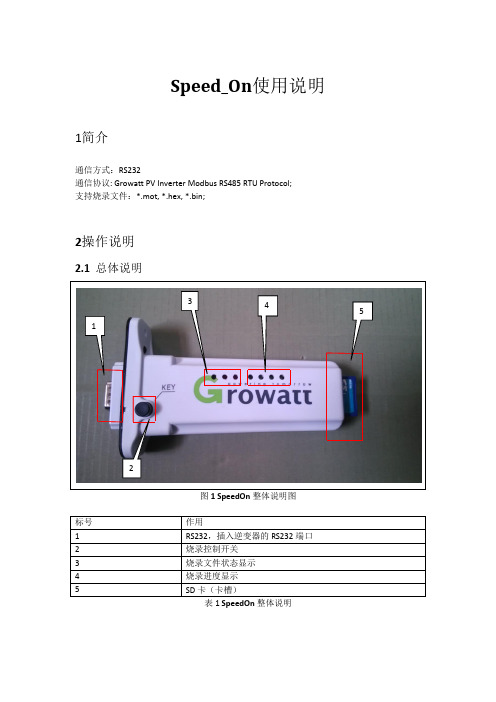
Speed_On使用说明1简介通信方式:RS232通信协议: Growatt PV Inverter Modbus RS485 RTU Protocol;支持烧录文件:*.mot, *.hex, *.bin;2操作说明2.1 总体说明3 45 12表1 SpeedOn整体说明2.2 SD卡操作说明2.2.1烧录文件复制到SD卡中,修改烧录文件名,烧录文件名小于等于8个字母;图2 SD卡中新建“BCONFIG.txt”2.2.2在SD卡中建立“BCONFIG.txt”文件,在此文件中写下如下的内容,一次最多烧录二个程序,XXXXXX代表的是烧录文件名称:1.XXXXXX2.XXXXXX图3 文件“BCONFIG.txt”中的内容2.3 SpeedOn 烧录操作说明2.3.1 SpeedOn插入RS232中(注意RS232供电的2 PIN拨码开关需要闭合),闭合DC电源,按一下烧录开关2,等待状态灯亮;表2 读取到SD卡中文件状态显示2.3.3按下按键2S钟左右,SpeedOn开始烧录,烧录说明显示如下:(1表3 程序烧录时状态显示(2)烧录进度显示,共有4个LED显示,4个LED分别代表25%、50%、75%、100%;烧录完成后烧录进度等会全灭;点亮一个代表烧录当前烧录到多少,其他的灯以流水灯的状态存在;(3)烧录完成后,机器会重启,烧录完后如图4所示:(里面仅一个程序时)图4烧录完成(仅烧录一个程序)2.4 异常烧录:烧录mot文件,烧录中途断掉后,需要拔出SpeedOn烧录设备,等待大约10s,状态灯有显示,按下按键3s后,等待10s左右,SpeedOn开始烧录数据。
烧录hex文档失败后,需要拔出SpeedOn,插入后,按下按键,显示按照正常显示一样;。
SPEEDY 操作手册

SPEEDY 操作手冊一、一般DOS操作指令:1.MD:MAKE DIRECTORY---建立子目錄。
Ex.:C:\JOBS\>md 目錄名稱2.CD:CALL DIRECTORY---呼叫子目錄。
Ex.:C:\>CD 目錄名稱3.REN:RENAME---變更檔案名稱。
Ex.:C:\JOBS\>REN 檔案名稱.副檔名新名稱.新副檔名4.COPY:COPY---複製。
Ex.:C:\JOBS\目錄\>COPY G:\1234\*.*5.DIR:DIRECTORY---列出明細。
Ex.:C:\JOBS\>DIR6.變更磁碟機:直接輸入磁碟機代碼。
Ex.:C:\>G:7.DEL:DELETE---刪除檔案。
(此指令請小心使用)Ex.:C:\JOBS\1234\DEL *.LST二、進入SPEEDY系統1.FPH進入主畫面註:移動游標選定後按ENTER鍵即可進入上述各個功能選項P.12.進入測試目錄:註:移動游標至欲修改之資料後按ENTER鍵,即可修改。
P.24.進入螢幕標點畫面:按Alt + R 鍵入G,按ENTER鍵,選擇REARPIN.GBR後,按ENTER鍵,將REARPIN.GBR轉檔成REARPIN.APF。
重複上述動作,分別選擇MEHOLE.GBR及FRONPIN.GBR可將GBR檔轉換成APF檔。
按Ctrl + U 鍵入H,按ENTER鍵,選擇*. HLS檔案後,按ENTER鍵,可將測試資料轉檔為機台所需之資料(LST 檔)。
在此畫面下設定定位點(Fiducial):①F11:選擇方形PAD(若有線路者以垂直者為佳),選定後按J,將游標跳至PAD 的中心點後,按F11功能鍵可得 。
②F12:選擇方形PAD(若有線路者以平行者為佳),選定後按J,將游標跳至PAD 的中心點後,按F12功能鍵可得▫。
③Rotate:選擇方形PAD(若有線路者以垂直者為佳),選定後按J,將游標跳至PAD的中心點後,按Alt + O鍵可得 。
SpeedFlow速度测量仪器用户操作指南说明书

SpeedFlowMeasurement of velocityfor solidsSuperior with SolidsCONTENTS Page 1. System overview . . . . . . . . . . . . . . . . . . . . . . . . . . . . . . . . . . . . . . . . . . . . . . . . . . . . . . . . . . . . . . . . . . . . . . . 31.1 Using the optional C1-box . . . . . . . . . . . . . . . . . . . . . . . . . . . . . . . . . . . . . . . . . . . . . . . . . . . . . . . . . . . 32. Function . . . . . . . . . . . . . . . . . . . . . . . . . . . . . . . . . . . . . . . . . . . . . . . . . . . . . . . . . . . . . . . . . . . . . . . . . . . . . . 43. Safety . . . . . . . . . . . . . . . . . . . . . . . . . . . . . . . . . . . . . . . . . . . . . . . . . . . . . . . . . . .. . . . . . . . . . . . . . . . . . . . . 5Normal use . . . . . . . . . . . . . . . . . . . . . . . . . . . . . . . . . . . . . . . . . . . . . . . . . . . . . . . . . . . . . . . . . . . . . . . . 5 3.1Identification of hazards . . . . . . . . . . . . . . . . . . . . . . . . . . . . . . . . . . . . . . . . . . . . . . . . . . . . . . . . . . . . . 5 3.2Operational safety . . . . . . . . . . . . . . . . . . . . . . . . . . . . . . . . . . . . . . . . . . . . . . . . . . . . . . . . . . . . . . . . . . 5 3.3Technical statement . . . . . . . . . . . . . . . . . . . . . . . . . . . . . . . . . . . . . . . . . . . . . . . . . . . . . . . . . . . . . . . . 53.44. Mounting and installation . . . . . . . . . . . . . . . . . . . . . . . . . . . . . . . . . . . . . . . . . . . . . . . . . . . . . . . . . . . . . . . 6Supplied equipment . . . . . . . . . . . . . . . . . . . . . . . . . . . . . . . . . . . . . . . . . . . . . . . . . . . . . . . . . . . . . . . . 6 4.1Required tools . . . . . . . . . . . . . . . . . . . . . . . . . . . . . . . . . . . . . . . . . . . . . . . . . . . . . . . . . . . . . . . . . . . . . 6 4.2Mounting of the sensor . . . . . . . . . . . . . . . . . . . . . . . . . . . . . . . . . . . . . . . . . . . . . . . . . . . . . . . . . . . . . 6 4.3Mounting of the transmitter . . . . . . . . . . . . . . . . . . . . . . . . . . . . . . . . . . . . . . . . . . . . . . . . . . . . . . . . . 94.45. Electrical connection . . . . . . . . . . . . . . . . . . . . . . . . . . . . . . . . . . . . . . . . . . . . . . . . . . . . . . . . . . . . . . . . . . 106. Commissioning . . . . . . . . . . . . . . . . . . . . . . . . . . . . . . . . . . . . . . . . . . . . . . . . . . . . . . . . . . . . . . . . . . . . . . . 117. Menu structure of the SpeedFlow configuration program . . . . . . . . . . . . . . . . . . . . . . . . . . . . . . . . . . 128. System settings in detail . . . . . . . . . . . . . . . . . . . . . . . . . . . . . . . . . . . . . . . . . . . . . . . . . . . . . . . . . . . . . . . 139. Brief description of the PC operating software . . . . . . . . . . . . . . . . . . . . . . . . . . . . . . . . . . . . . . . . . . . . 15DRC tab . . . . . . . . . . . . . . . . . . . . . . . . . . . . . . . . . . . . . . . . . . . . . . . . . . . . . . . . . . . . . . . . . . . . . . . . . 15 9.1System tab . . . . . . . . . . . . . . . . . . . . . . . . . . . . . . . . . . . . . . . . . . . . . . . . . . . . . . . . . . . . . . . . . . . . . . . 16 9.29.3List tab . . . . . . . . . . . . . . . . . . . . . . . . . . . . . . . . . . . . . . . . . . . . . . . . . . . . . . . . . . . . . . . . . . . . . . . . . . 17Trend tab . . . . . . . . . . . . . . . . . . . . . . . . . . . . . . . . . . . . . . . . . . . . . . . . . . . . . . . . . . . . . . . . . . . . . . . . . 18 9.4Sensor tab . . . . . . . . . . . . . . . . . . . . . . . . . . . . . . . . . . . . . . . . . . . . . . . . . . . . . . . . . . . . . . . . . . . . . . . .189.510. Maintenance . . . . . . . . . . . . . . . . . . . . . . . . . . . . . . . . . . . . . . . . . . . . . . . . . . . . . . . . . . . . . . . . . . . . . . . . . 1911. Warranty . . . . . . . . . . . . . . . . . . . . . . . . . . . . . . . . . . . . . . . . . . . . . . . . . . . . . . . . . . . . . . . . . . . . . . . . . . . . . 1912. Troubleshooting . . . . . . . . . . . . . . . . . . . . . . . . . . . . . . . . . . . . . . . . . . . . . . . . . . . . . . . . . . . . . . . . . . . . . . 1913. Technical data . . . . . . . . . . . . . . . . . . . . . . . . . . . . . . . . . . . . . . . . . . . . . . . . . . . . . . . . . . . . . . . . . . . . . . . . 201. System overviewA complete measurement point consists of the following components:•Transmitter in DIN rail housing•Sensor accommodation for welding to the pipeline•Sensor (union nut, distance washer, sealing ring for adjusting to the wall thickness)•Operating instructions•C1-box (optional)The measuring sensor is connected to the transmitter using a shielded 4-wired cable with the length of the cable not exceeding 300 m.1.1 Using the optional C1-boxThe C1-box is a terminal block with a fuse and terminal resistor for connecting longer bus and supply lines.2. Function•The SpeedFlow is a measuring system which has been specially developed for measuring the speed of solids being transported.•The sensor uses the triboelectric effect. It is only used in metallic pipelines.•The electrodes fitted in the pipeline receive an electrical pulse from the solid particles as they pass.The received signals are evaluated using an auto-correlation process which thus calculates the speed.• A measurement point generally consists of the sensor, C1-box and the transmitter.Fig. 2: SpeedFlow sensor in the pipeline3. SafetyThe SpeedFlow measuring system has a state of the art, reliable design and and has been tested and found to be in a perfectly safe condition when it left the factory. Nevertheless the system components may present dangers to personnel and items if they are not operated correctly.The operating instructions can therefore be read in full and the safety instructions followed to the letter.If the device is not used correctly for its intended purpose the manufacturer's liability and warranty will be void.3.1 Normal use•The measuring system may only be installed in metallic pipes to measure the medium passing through them.It is not suitable for any other use or measuring system modifications.•Only genuine spare parts and accessories from SWR engineering may be used.3.2 Identification of hazards•Possible dangers when using the measuring system are highlighted in the operating instructions using the following symbols:•This symbol is used in the operating instructions to denote actions which, if they are not performed correctly may result in death or injury.Attention!• This symbol is used in the operating instructions to denote actions which may result in danger to property.3.3 Operational safety•The measuring system may only be installed by trained, authorised personnel.•In case of maintenance-work on the pipe or on components of the SpeedFlow sensor, make sure that the piping is in unpressurised condition.•Switch off the power supply before completing any maintenance work, cleaning work or inspections on the pipelines or the SpeedFlow components.•The sensor must be taken out of the pipeline before any welding work.•The components and electrical connections must be inspected for damage at regular intervals. If any signs of damage are found, they must be rectified before the devices are used again.3.4 T echnical statement•The manufacturer reserves the right to adjust technical data to technical development without notice.SWR engineering will be delighted to provide information about what the operating instructions is up to date and any amendments which have been made to it.4. Mounting and installation4.1 Supplied equipment•Transmitter in DIN rail housing•Sensor accommodation for welding to the pipeline•Sensor (union nut, distance washer, sealing ring for adjusting to the wall thickness)•Operating instructions•C1-box4.2 Required tools•Ø 20 mm-twist drill bit•32 mm open-ended spanner for union nut•Pliers for circlips (Ø 20 mm) to adjust the sensor to the wall thickness4.3 Mounting of the sensorProceed as follows to install the sensor:•Decide on the installation position on the pipe. It should be installed from the top on horizontal or angled pipelines.•Weld the sensor accommodation on to the pipe.•Drill through the pipe through the sensor (Ø 20 mm). Ensure that the borehole is not angled so that the sensor can be installed precisely later.Warning!•After drilling it is essential to check whether the drill bit has caused any burr on the borehole edges.Any burr on the pipe must be removed using a suitable tool. If the burr is not removed it may affect the sensor's calibration.•If the sensor is not installed immediately insert a dummy plug until it is installed (see also fig. 4). The dummy plug must be inserted together with the seal, two sealing rings and the circlips for shafts and secured using the union nut. Use a 32 mm open-ended spanner to tighten the union nut.Fig. 4: Installation of the sensoraccommodation and the dummy plug Distance washer 1 mmO-ring-type sealingring 19 x 2Sensor accomodationUnion nutCirclips for shaftsDummy plugqqqqqqq•Remove the dummy plug to insert the sensor.•The sensor is supplied ready-assembled for the specified wall thickness or, if no wall thickness was specified, to a wall thickness of 4 mm. Check again that it is correctly adjusted before installation (see table). If necessary the wall thickness must be remeasured with a depth gauge. The weld-on socket is93 mm long. It is important that the sensor does not project into the pipe. The sensor may be up to1 mm inside the pipe wall without this causing a measurement error.Wall thickness (mm)Position on the sensor neck Number of distance washers3.04.05.56.58.09.010.511.513.014.011223344552121212121•Now the sensor is put into the sensor accommodation and screwed with the union nut according to figure 5a.Fig. 5a: Installation of sensor accommodation and sensorSensor accommodationO-ring-type sealing ring 19 x 2Distance washer 1 mm Circlip for shafts 20 x 1.2Distance washer 1 mm Union nut Sensorqqqqq qq12 • and align it longitudinally to the pipe axis as marked on the sticker (Fig. 5b). The two sensor-rods must beinline with the flow. Then seal the measurement point with the union nut.Fig. 5b: Sensor alignment▼Flow d irectio n4.4 Mounting of the transmitter•The entire transmitter can be installed at a maximum distance of 1 km from the sensor.The housing is prepared for installation on a DIN rail to DIN EN 60715 TH35.Fig. 6: DIN rail housing for the transmitterFig. 7: Field housing for the C1-box5. Electrical connectionFig. 9: Electrical connection of the transmitter6. CommissioningCheck the following:•The correct connection between the sensor and transmitter.•The correct installation of the sensor on the internal wall of the transport pipe.If despite the above being correct the measurement is still not successful, consult SWR.Commissioning the SpeedFlowThe sensor is an absolute measuring device and must be parameterised during the commissioningprocedure. The menu functions in the supplied SpeedFlow configuration program are essentially self-explanatory. The program has been tested with all current Windows operating systems.The connection may be made using the RS 232 C interface (socket in the front panel) using the supplied cable or using the integral RS 485 interface (bus-capable) on screw terminals 11 and 12. By assigningdifferent addresses to the various transmitter the devices can be actuated in the bus using the ModBusprotocol. The following is a brief introduction as a summary.All the changed values must be saved by exiting the menu level and confirming the save function.Starting the menu After starting the SpeedFlow configuration program, open the interface (COM1to 10 can be selected). Fix the baud rate at 9600 Bd.Set the address of the transmitter (standard = 1).Current output The output values are set in menu points 3.1 to 3.8.The output value (current) is assigned to the measuring range here.Standard 0 = 4 mAMax = 20 mAThe measuring range filter is used to adjust to slower recording devices or acontinuous output at the analogue output.Alarms can be entered by the user in menu 2.Analogue output is modified in menu 3 and can be adjusted here to suit theuser's requirements. (Between 0 - 22 mA)Storage After making changes they can be saved using menu point Device Program.If you confirm Overwrite calibration the change will be made.Following the menu parameters in detail:7. Menu structure of the SpeedFlow configuration program1. Measuring range1.1 T ag no Adjust material (10 digits)1.2 Start of measuring range Range 0 (999)1.3 End of measuring range Range 0 (999)1.4 Filter value Range 0.1 ... 99.9 s2. Alarms2.1 Alarm 12.1 Alarm type Select: Min / Max / None2.2 Alarm value-10 to 110 % in physical units2.3 Alarm down time Range 0.1 ... 99.9 s2.4 Alarm hysteresis0.1 ... 99.9 %2.5 Operating mode Select: Working / Closed-circuit principle2.6 Sensor alarm Alarm for sensor error: On / Off3. Analogue output3.1 Start of range Range: 0 ... 22 mA (standard: 4 mA)3.2 End of range Range: 0 ... 22 mA (standard: 20 mA)3.3 MIN limit Range: 0 ... 22 mA (standard: 3 mA)3.4 MAX limit Range: 0 ... 22 mA (standard: 20 mA)3.5 Alarm value Range: 0 ... 22 mA (standard: 3 mA)3.6 Filter time Range: 0.1 ... 99.9 s (standard: 1 s)3.7 Calibration: 4 mA Adjust output current (4 mA calibrated)3.8 Calibration: 20 mA Adjust output current (20 mA calibrated)8. System settings in detail1. MEASURING RANGE1.1 T ag no.Freely selectable designation of the measuring medium or place,max. 10 characters1.2 Start of measuring rangeEnter the value of the required start of the measuring range.Normally 0.0.1.3 End of measuring rangeEnter the value of the required end of the measuring range.1.4 Filter valueAdjustable damping for the display in seconds.Range: 0.1 ... 99.9 s2. ALARMSEffect on the relay2.1 Alarm typeMin/Max - upper or lower limit value2.2 Alarm valueTrigger thresholdRange -10 ... 110 % of the measuring range values in physical units.2.3 Alarm down timeResponse time for how long the value must be below or above the limit valuebefore the alarm relay switches. Range: 0.1 ... 99.9 s2.4 Alarm hysteresisValue to reset the alarm.Range: 0.1 ... 99.9 % of the defined measuring range.2.5 Operating modeSelect the contact: Work or closed-circuitNO (working current) - NC (closed-circuit current)2.6 Sensor alarmAlarm for sensor errorON /OFF3. ANALOGUE OUTPUT3.1 Start of rangeValue to be set for minimum current output.(Standard 4 mA) - Range 0 ... 22 mA3.2 End of rangeValue to be set for maximum current output.(Standard 20 mA) - Range 0 ... 22 mA3.3 MIN limitMinimum current output value to be set. Range 0 ... 22 mA (standard 3 mA)3.4 MAX limitMaximum current output value to be set.Range 0 ... 22 mA (standard 20 mA)3.5 Alarm valueOutput value to be set for alarm (sensor error or internal alarm), at the same time the relay drops out.Range 0 ... 22 mA (standard 3 mA)3.6 Filter timeDamping to be set for the current output.Range 0.1 ... 99.9 s (standard 1 s)3.7 Calibration 4 mAMin. output current to be setAdjust to the external measuring system (if display is different).Adjust the output current to 4 mA using the and keys.3.8 Calibration 20 mAMax. output current to be setAdjust to the external measuring system (if display is different).Adjust the output current to 20 mA using the and keys.<><>9. Brief description of the PC operating softwareThe “SPF Service V.5.xx (E)” PC software can communicate with a sensor via RS 232 (front connector on the rail [DRC]) or via RS 485 (screw-terminal).The ModBus RTU log is used.•Interface standard is 9600 baud, 8 data bits, even parity, 1 stop bit.•Standard sensor address is 1.•Only one point-to-point connection can be established with one sensor via RS 232.• A bus system can be established via RS 485.• 1 sensor can be portrayed with the standard PC software.•Up to 10 sensors can be portrayed with an optional PC software.All settings required to operate the system can be activated via the PC software.•Interfaces and log file settings (data logger function) are activated in the System tab.•Current output, the signal’s measuring range, alarms and relay actions are set in the DRC tab.•Parameters for improving the measurement procedure are set in the Sensor menu.•The List and Trend tabs provide an overview of the measurement results from the measuring points.9.1 DRC tabSettings for customer system signals, see section 7.9.2 System tabLanguage:•German or English can be selected.Backup files:•Saving program data:Saves the settings from the PC program in a file so that they are available during the next start-up.These are automatically saved at the end of the program.•Save sensor parameters in a file / load sensor parameters from a file:Here, the measuring point parameters (DRC and sensor) can be saved into and read back from a file.•All backup files are saved in text format and can be opened with a normal text program. Communication:•COM port (COM1 to 10) of the interface used on the PC.• The baud rate for the communication must be the same on both devices.• If the baud rate for the DRC is changed, the new transmission rate will only apply after the DRC has been switched off and on again.• ModBus query rate and Timeout:Here, the intervals at which a query is sent to the connected system is set along with the time frame in which the response can be expected.Logging (PC data logger):• A log file is created for the sensor. The logs are saved as CSV files.•The decimal separator (comma or point) can be defined by CSV with decimal point.•The logging time interval can be entered as Log interval [ms].•The file name is automatically filled in with the ModBus address and serial number of the sensor in order to enable clear identification.•Automatic numbering of the files can be activated with the Auto-Increment option.The file numbers then increase each day (at midnight) and each time the program is started.•The file number can be manually adjusted with “Increase no.” or “Reset no.”.•The file path and active logging can be set in the footer.No COM-port scan (auto-start):If this option is selected, when starting, the software immediately begins with the most recently configured port and protocol settings.9.3 List tabHere, the sensor is portrayed in an overview list.Up to 10 sensors can be managed with the optional PC software.The sensor is portrayed with its main measurement value Vm and several secondary measurement values which provide information about the quality and condition of the measuring point.All values in this list are held in the log file and portrayed as trend lines (Trend tab).9.4 Trend tabAll values measured by the sensor from the overview list (List tab) are portrayed here as trends.Vm and Vcc are scaled on the left scale and all other values are scaled on the right scale.If upper and lower scale values are entered in the grey fields , these will be used - if the fields remain empty,automatic scaling will take place. With Zoom and Pos , the signal’s resolution and history can be set.9.5 Sensor tabThe measurement parameters, measurement values and quality numbers of the currently selected sensor are portrayed here. These parameters are provided as default settings or, if necessary, are selected when starting upthe sensor for the first time and permanently saved in the sensor.These parameters should only be set by trained personnel - as a rule by SWR employees - and should only be adjusted in special cases.10. Maintenance•Switch the power supply off before all maintenance and repair work on the measuring system.The transport pipe must not be operational to replace the sensor.•Repair and maintenance work may only be carried out by electricians.•The system requires no maintenance.11. WarrantyOn condition that the operating conditions are maintained and no intervention has been made on the device and the components of the system are not damaged or worn, the manufacturer provides a warranty of 1 year from the date of delivery.In the event of a defect during the warranty period, defective components will be replaced or repair at SWR's plant free of charge at discretion. Replaced parts will become SWR's property. If the parts are repaired or replaced at the customer's site at its request, the customer must pay the travelling expenses for SWR's service personnel.SWR cannot accept any liability for damage not suffered by the goods themselves and in particular SWR cannot accept liability for loss of profit or other financial damages suffered by the customer.Warning!The electrical installation may only be inspected by trained personnelProblem Cause MeasureMeasuring system does not work.POW LED not lit.RUN LED not lit.Power supply interrupted.Check the power supply.Cable break.Check the connection cables for a possible cable break.Fuse defective.Replace fuse.Device defective.Notify SWR and rectify the error as instructed on the telephone.Measuring system does not work.POW LED lit.RUN LED not lit.Microprocessor does notstart.Switch the power supply off and on again.Remove programming cable.Measuring system works.POW LED lit. RUN LED flashes quickly.No sensor communication.Sensor defective.Cable break between sensor and measuring system. Sensor connected incorrectly.Check connection cable.Sensor defective.Replace sensor.Sensor not receiving 24 Vsupply.Make sure the power supply is connected.Excessive voltage drop in thesupply cable to the sensor.Increase supply cable cross-section.Measuring systemoutputs incorrect values.Calibration incorrect.Calibration factor changed. Normal V = 1Switch output relaychatters.Hysteresis too low.Increase hysteresis. Check for fault caused by external consumer.Do not open, as otherwise the warranty claim expires!12. T echnical dataSensor Housing material Stainless steel 1.4571Protection category IP 65, dust Ex zone 20 or gas Ex zone 1 (optional)Operating temperature Sensor tip -20 ... +80 °C Optional: -20 ... +200 °C Sensor electronic: 0 ... +60 °C Max. working pressure 1 bar, optional 10 bar Sensor tip material Tungsten carbite Transmitting power Max. 5 mW Weight Approx. 1.5 kgDimensions Ø 60, Ø 20, L 320 mm (incl. rod length)Accuracy ± 1 % in calibrated rangeTransmitter Power supply 24 V DC ± 10 %Power consumption 20 W / 24 VA Protection category IP 40 to EN 60 529Operating temperature -10 ... +45 °C Dimensions 23 x 90 x 118 (W x H x D)WeightApprox. 172 g DIN rail mountingDIN 60715 TH35Connection terminals Cable cross-section 0,2 – 2,5 mm² [AWG 24-14]Current output signal 4 ... 20 mA (0 ... 20 mA), load < 500 WAlarm output Relay with switching contact - Max. 250 V AC, 1 A Data backupFlash memory (A l l r i g h t s r e s er v e d .)SWR engineering Messtechnik GmbHGutedelstraße 31 · 79418 Schliengen (Germany)Fon +49 7635 827248-0 · Fax +49 7635 827248-48 · Superior with Solids。
- 1、下载文档前请自行甄别文档内容的完整性,平台不提供额外的编辑、内容补充、找答案等附加服务。
- 2、"仅部分预览"的文档,不可在线预览部分如存在完整性等问题,可反馈申请退款(可完整预览的文档不适用该条件!)。
- 3、如文档侵犯您的权益,请联系客服反馈,我们会尽快为您处理(人工客服工作时间:9:00-18:30)。
PCB和鋼板的最佳位置
• 3.經過優化後,點選Calibrate ( 校正 )機器會依設定的基准點自動校正影像資料
( 模擬測試 )。
4. 完成前兩步後,點擊Test Align機器會依設定的基准點自動移動並測試調整
enable) ,則可使用 Fine zero 鍵,系統會自動偵測刮刀零壓力
• 刮刀各高度的設置
校正刮刀 ( Calibrate squeegees )
設置刮刀高度先將的移動距離調好 Advance 1.Squeegee movement (調整刮刀每一次移動的距離)
>Coarse steps (上下移動粗調每一次的距離) >Fine steps (上下移動微調每一次的距離) 2.Squeegee heights above stencil (刮刀各位置高度設定) > Non-print (未印刷 ) > Paste release (錫膏脫離) > Stencil inspection (鋼板視覺檢測) 可使用Move to 確認此高度是否合適 3.Feedback system >Feedback enabled 啟動刮刀壓力自動回授控制 a.ActiveБайду номын сангаасduring whole of print cycle (每一次使用) b.Active only at start of print cycle (只在剛開始第一次使用)
• Clean during production every啟動自動擦拭功能 • Frequency (prints):每印幾片清潔一次
• Wipe ( 擦拭行程 ) • >Strocke : (一般為總行程=板寬度+30mm ) • >Strock start : ( 一般為 -20mm )
• Wet(Dry)mode ( 干擦/濕擦 ) 模式 • >Wipes: ( 做幾次擦拭 ) 1-10次 • >Speed: ( 擦拭速度 ) 5-100mm/s • >Paper Advance: ( 每次進紙長度 )一般為最小值
• PCB與鋼板的偏差微調
第八步 校正刮刀(Calibrate squeegees)
校正刮刀 ( Calibrate squeegees )
注:在校正刮刀前,先安裝上前後刮刀 Standard 1.選擇按後Rear/Front前並且選擇 Coarse(粗調)或Fine(微調)
點選 Initialize Squeegees 鍵刮刀會回歸原點 開始點選向下箭頭直到刮刀全部剛剛接觸板為准(在Advanced中可選
Speed line
(MPM Accuflex)
全自動印刷機操作流程
開機步驟
1. 將機器後端主電源保險開關(20A)開至ON(下頁有圖示), 檢查氣壓 供應必需在5BAR-24lites/minute.
2. 機器前端主開關(下頁有圖示)旋轉至1(ON)位置,機器開始讀取控 制程式
3. 當螢幕出現畫面時,輸入開機名字及密碼後點選OK鍵。輸入方式 由鍵盤輸入
座標數據設置以PCB左下角為原點 5. 選好基准點後點擊OK鍵完成設置
• 第三步 建立鋼板(Stencil)數據及定位鋼板
設置鋼板數據步驟如下
• 設置鋼板總寬度(注意:分有架鋼板無架鋼板),邊緣寬度(注意:邊緣 寬度分為有架和無架40.0mm)。
• 點擊 Number of images(圖庫數量)鍵,一般為默認值為( 1 ). • 選擇PCB在鋼板中的位置 • Rear(向後計算),Front(向前計算),Center(向中心計算),按下
• 在中間上方處可修改影像資料名稱
• 在Minimum coverage( 最小偏差值 ),Maximum coverage ( 最大偏差值 ) 兩個值可修改印刷偏差
• 完成以上步驟即可開始印刷
關機步驟
1. 選擇File畫面下Exit,此時將出現如下之提示: File C:\FILES\JASON.SMT has changed do you want to save the change ? 詢問: Yes ; No ; Cancel ; ( 若未修改檔案則不會出現上面提問 )
• 5.需要時可調整Brightness,Contrast及 Threshold。亦可調整 Set
Correlation Box 調整搜索范圍。 • 完成測試後,點擊Board to print 鍵模擬印刷,通過目測鋼板與PCB的偏差,
如有偏差,在點擊Board to vision回歸原點後,在點擊Print Offset鍵進入微調 偏差的操作面板,調整完畢,點擊Test Align鍵重新測試後,再 進行模擬印刷, 目測,調整,直到最佳效果為止,點擊Close鍵關閉。保存參數
刀使用相同的印刷參數。 • Speed ( 印刷速度 ) ( 1-200mm ) • Pressures ( 刮刀壓力 ) ( 0-20kg ) • 2.Stroke ( 印刷行程 ) • Start ( 起始點 ) ( -20-514mm ) • Distance ( 印刷行程 ) ( 50-514mm ) • Squeegee forward offset ( 刮刀前進補償值 ) ( 0-50mm ) • 3.Snap-off ( 脫離速度和距離設定 ) • Speed ( 脫離速度 ) ( 0.2-10mm/s ) • Distance ( 脫離距離 ) ( 0-1mm )
擇移動距離 可使用Use rear squeegee default使用前一次設定值,再用微調修正 按 Calibrate 鍵便可設定刮刀校正值,前後刮刀校正順序不限 2.如要儲存目前設定為基准值請點選Store new valves as default 3.要使用前次的設定值請點選 Use rear (front) squeegee default 4.要移動至前次的設定值請點選Move to rear (front) squeegee default 5.若使用刮刀壓力自動回授系統者(於 Advanced 中選 Feedback
• 2.選取合適的影像類型後, 在PCB上找到 做影像類型的元件位置,出現如下章的界 面
• 選取如零件腳lead大小的窗口雙擊變蘭色,藍色框如所選Lead大小,則為成 功,反之不行,成功後按Next鍵,即進入下一步,按Next 鍵直至完成,系統 會自測影像是否成功。完成後即可關閉(CLOSE)
• 操作成功後,在綠色區域出現影像圖,在右邊details下出 現所做影像資料,雙擊Name即可出現如下章界面
• 印刷參數設置
• 第七步 做PCB和鋼網的基准點 (Edit vision porfile)
做基准點步驟如下
• 1.在Site中選(Site 1或 Site 2 ) 後,在 Weight 下選取PCB或Stencil (鋼網),同
一方位做好基准點。方法兩種如下:第一,點選Learn(學習)鍵,再點選基准點, 機器會自動設定及捉取基准點的圖形及識別資料。第二,在基准點上直接點擊 兩下,機器會自動設定及捉取基准點的圖形及識別資料。
在5BAR-24lites/minute.
2. 左下圖:機器前端主開 關旋轉至1(ON)位置,機 器開始讀取控制程式
開機界面提示
• 左上圖提示輸入使用者 密碼
• 左下圖是輸入密碼點擊 OK鍵後,提示打開系統 電源<System power>開 關(綠色按鈕),再點擊 OK鍵,即可進入操作系 統
機器正面按鈕
2. 右上圖表示PCB 與鋼板位置優 化成功
3. 右下圖表示PCB 與鋼板基准點 校對成功
4. 右上圖中提問:是否 要從軌道上退下PCB?
5. 右下圖提問:輸送帶 上已經有PCB,你要 印刷這PCB嗎?
6.下列提示為:你想搬運隊列位置上的 PCB做影像設置嗎? 肯定:按”Yes”, 否定:按 ”No” , 退出:按 “Cancel”,
4. 之後螢幕出現開機畫面後,請旋松紅色E-stop開關和按下前方綠色 System Power開關後,請點選OK鍵(下頁有圖示)
5. 機器開始進入主畫面,並載入機器基本設定及機器各項回歸原點, 之後可於螢幕上看見相關畫面,即表示開機完畢。
1. 左上圖:將機器後端主 電源保險開關(20A)開至 ON, 檢查氣壓供應必需
• 第九步 自動清潔鋼板參數(Edit stencil profile)
• 自動清洗鋼板參數修改(Edit stencil profile)
自動清洗鋼板Setup stencil cleaner
• Cleaning mode • Dry ( 干擦 ) ,Wet ( 濕擦 ) ,及Wet and Dry ( 兩種均使用 ) • >Alternate wet/dry (干濕擦互替換先行擦拭<當選則多次擦拭時才選擇此項 ) • >Start with wet wipe ( 從濕擦開始 ) • >Start with dry wipe ( 從干擦開始 )
• 左圖中紅色開關為緊 急開關,綠色開關為 系統電源開關 .
• 第一步 建立新機種( NEW )
• 第二步 建立PCB數據,調整軌道及選取基准點
各參數設置步驟如下 (Edit PCB information)
1. 輸入PCB的長度,寬度,厚度數據 2. 清理軌道上PCB和托盤上的頂針 3. 按下Adjust Rail鍵自動按數據調整軌道寬度 4. 選取PCB與鋼網相對應位置的兩個基准點(一般為兩個),
• 按下PCB vision inspection (PCB視覺檢測)鍵後出現以上對話窗口
• 將鋼網和PCB安放到指定位置再點擊<Yes>鍵
• 第十步 建立印刷PCB視覺資料(PCB vision inspection )
