HD2013 操作手册
HDJD-JD13开发板简介说明书

HDJD-JD13Development KitHardware User GuideIntroductionThank you for purchasing the HDJD-JD13 Development Kit from Avago Technologies. The HDJD-JD13 Kit is a simple development board, which demonstrates the capabilities of the 24-pin HDJ D-J822 color management controller device.The development kit can be used stand-alone with a programmed system controller on-board, connect to another controller system (using I2C interface) or connect direct to an IBM-PC computer (using parallel port). Sample programs are provided to demonstrate the unique features of the device.The HDJD-JD13 Development Kit comes with the following:•HDJD-JD13 Development Board (Figure 1-1)•Sample Device•CD-ROM, which contains:-HDJD-JD13 Development Kit Hardware User Guide-Development Kit Backlight System Design Guide-ICM Program User Guide-Sample System Controller Program Guide-Application Notes-Datasheets-Sample System Controller Program CodesIf you are missing any part of the kit, please contact your nearest Avago Technologies sales office listed in the back of this publication for help.2HDJD-JD13 DEVELOPMENT BOARDThe HDJD-JD13 development board has the following hardware features:1.24-pin SOIC packaged HDJD-J822 device2.28-pin DIP packaged PIC18F252 device3.Onboard +5V switching regulator for direct input from 12V 1000mA AC/DC wall adaptor4.25-way parallel port and associated hardware for direct connection to a parallel port interface5.In-Circuit Serial Programming (ICSP) connector for programming onboard system controller6.Four push button switches for selecting 4 different set of white color temperature point or as external stimulus7.Two push button connected to HDJD-J822 brightness and color setting pin 8.10-way DIP switch for setting various control pins of HDJD-J822 device9.6-way DIP switch for individual RGB gain control of the onboard color sensor10.External I/O connector that port various control pins of HDJD-J822 device externally 11.PWM output connector that connects to external LED driver card 12.External I 2C connector for interfacing to external controller board 13.1K (128 x 8) Serial I 2C EEPROM 14.Color RGB sensor connector15. 3.5 inch lightguide panel with 8 RGB (Red-Green-Blue) Side-firing LED as light source 16.10 MHz crystal oscillator for PIC18F252 system controller clock operation 17.Onboard RC oscillator for HDJD-J822 color management controller 18.LX1991 LED driver to drive the 8 RGB LEDs 19.Prototype area for user hardware 20.RGB color sensorFigure 1. HDJD-JD13 Development Board Hardware.152019189171410111234191825761613SAMPLE PROGRAMSThe HDJD-JD13 Development Kit includes a CD-ROM with sample demonstration system controller program. This program can be used with the included HDJD-J822 color management controller andPIC18F252 microcontroller. Demo source code and compiled code (one Hex file) are provided.HDJD-JD13 DEVELOPMENT KIT HARDWARE USER GUIDEThis guide describes the HDJD-JD13 Development Board, including hardware component layout and schematic. Tutorial and demonstration software user guide may be found in the kit programming code example document, which are included in the CD-ROM. Detailed information on HDJD-J822 color management controller and the onboard PIC18F252 system controller can be found in the device’s respective data sheet.Chapter 1 : Introduction - This chapter introduces the HDJD-JD13 Development Kit and provides a brief description of the hardware.Chapter 2 : Hardware Description – This chapter decribes in detail the hardware of theHDJD-JD13 Development Board.REFERENCE DOCUMENTSReference documents listed below are included in the CD-ROM.•Individual Technical Data Sheets and Reference Manuals:-Avago HDJD-J822 color management controller-Avago HDJD-S831 RGB color sensor-Microchip PIC18Fxx2 system controller-STMicroelectronics 1k-bit/8 Serial I2C EEPROM-Microsemi LX1991 LED driver•Application Notes•Application Example•Development Kit Backlight System Design Guide•ICM Program User Guide•Development Kit Program Code-Example3Hardware DetailThe HDJD-JD13 Development Kit hardware is extremely simple and is intended to illustrate the ease of use of the Color Management Controller. The development board features the following hardware elements:COLOR MANAGEMENT CONTROLLER AND SYSTEM CONTROLLERThe board is incorporated with two processors, one is the HDJD-J822 color management controller and the other is the Microchip PIC18F252 system controller.DISPLAYEight Side-Emitting RGB Light Emitting Diodes (LED) are connected to emit colored light to a 3.5 inch lightguide. This lightguide has micro-dot printed on the bottom side which lights up the whole lightguide, causing it to glow in color (depending on what color setting is input to the color management controller. One green LED is provided to determine whether there is power to the development board (LED on) or not (LED off).POWER SUPPLYThe development board has a switching regulator that will step-down the 12V input to provide +5V supply needed to power up all the components onboard plus driving the eight LEDs. An external 12V, 1000mA or more unregulated DC supply can be plugged into J1.Note: The HDJD-JD13 Development Kit does not include a power supply.PARALLEL PORTA parallel port interface is provided for easy interfacing with an IBM-PC computer. The port is used to emulate I2C communication using software to perform the communication translation job. Since no special hardware is needed on the parallel port side, hence normal 25-way to 25-way parallel port cable can be used to hook up the board with the computer.On the IBM-PC computer side, the BIOS -> Onboard Peripheral -> Parallel Port setting must be set to Output-Only or Standard mode, before you can run the demonstration PC software (included in theCD-ROM).LED DRIVERLX1991 LED drivers (U5-U10), from Microsemi, are included on the board to illustrate a typical LED driving method. User can choose to use their own LED driver circuit to drive their LEDs through the use PWM output pins on the external input-output connector.The data sheet of this LX1991 LED driver is included in the CD-ROM for user reference.4SWITCHESSeven switches provide the following functions:•PB1 – Active-high switch connected to Pin 9 (COLOR) of HDJD-J822•PB2 – Active-high switch connected to Pin 10 (BRIGHT) of HDJD-J822•PB3 – MCLR to hard reset the PIC18F252 system controller•PB4 – Active-high switch connected to Pin 4 (RA2) of PIC18F252 system controller•PB5 – Active-high switch connected to Pin 5 (RA3) of PIC18F252 system controller•PB6 – Active-high switch connected to Pin 6 (RA4) of PIC18F252 microcontroller•PB7 – Active-high switch connected to Pin 7 (RA5) of PIC18F252 microcontroller*By default, 4 different color points will be programmed for PB4-7 for quick demonstration purpose.When pressed, the switches are pulled high (+5V) (except for PB3, which is grounded). When idle, they are grounded (except for PB3, which is pulled high +5V).SENSOR INPUTFor HDJD-JD13 Development Board, it supports RGB color sensor input. A 3-pin header is provided for this purpose. Besides that, the development board also included a RGB color sensor module, located on top of the display panel, for feedback color management demonstration. HDJD-S831 color sensor is used on the development board.The S2 DIP switch is used to set the gain of the individual R,G and B channel of the color sensor used on the development board. Each channel gain is selectable through a 2-bit gain selector.•S2-1 – Green Gain-1•S2-2 – Red Gain-1•S2-3 – Green Gain-0•S2-4 – Red Gain-0•S2-5 – Blue Gain-1•S2-6 – Blue Gain-0For user information, this S2 gain switch is sensor dependent. Different sensor has different gain setup. The data sheet for this sensor is included in the CD-ROM for your reference.SERIAL EEPROMA M24C01 1K (128 x 8) serial EEPROM, from STMicroelectronics, is included on the board to illustrate I2C bus concepts and to store HDJD-J822 calibration data.5IN-CIRCUIT SERIAL PROGRAMMING (ICSP) CONNECTORBy way of the header connector (CON1), the PIC18F252 system controller can be connected for onboard reprogramming. The ICSP connector utilizes RB6 and RB7 of the system controller for in-circuit serial programming. This connector is compatible with Microchip Promate 2 programmer, which support ICSP interface.ADC INPUT LOW-PASS FILTERSince the LEDs are controlled by pulse width modulation output from the HDJD-J822, the sensor output will also be pulse width modulated. Each sensor channel needs to be averaged by passing the sensor output voltage through a low pass filter. On the board, this low pass filter is realized through a RC low-pass filter (R11/C5, R12/C7 and R13/C8).Further explanation on the resistor and capacitor selection is documented in the application note, which is included in the CD-ROM.OSCILLATOR OPTIONSThere are two oscillator onboard the development kit. One is for the HDJD-J822 color management controller and the other is for the PIC18F252 system controller. For HDJD-J822, an RC oscillator(2.5 MHz approximately) is supplied. The recommended resistor is 68 k W (R2) for the nominal oscillator frequency of 2.5 MHz and a PWM frequency of 610 Hz.For PIC18F252 system controller, a crystal oscillator (10 MHz) is supplied. If user would like to operate the onboard system controller at different frequency, this crystal oscillator (Y1) can be changed to other value.EXTERNAL INPUT-OUTPUT CONNECTORMost of the HDJD-J822 color management controller and HDJD-S831 color sensor pins are mappable on the external input-output connector. These pins include:•PWM output R/G/B(PWM R/G/B)•I2C SDA(SDA)•I2C SCL(SCL)•Error flag(ERR-FLAG)•Bright control(BRIGHT)•Color control(COLOR)•Clock selector(CLK_SEL)•I2C address A0(A0)•I2C address A1(A1)•Sleep trigger(SLEEP)•Clock reference(CLKREF)•External ADC voltage reference(VREF)•Color sensor input R/G/B(BLUE/GREEN/RED)•5V/+5V supply pin(5V/+5V)•AGND/DGND ground pin(AGND/DGND)6BOARD LAYOUT AND SCHEMATICSThe following figures show the parts layout (silkscreen) and schematics for the HDJD-JD13 Development board.Figure 2. HDJD-JD13 Development Board Parts Layout.7Figure 3. HDJD-JD13 Development Board Schematic. 8For product information and a complete list of distributors, please go to our website: Avago, Avago Technologies, and the A logo are trademarks of Avago Technologies Limited in the United States and other countries. Data subject to change. Copyright © 2007 Avago Technologies Limited. All rights reserved. Obsoletes AV01-0625ENAV02-0067EN January 8, 2007。
HDMI完全使用手册(详细说明)

HDMI完全使用手册第一章我们为什么需要数字传输接口 (3)第一节数字化影音时代模拟接口的缺陷 (3)第二节HDMI标准横空出世 (4)第三节HDMI标准的主要特性和优势 (6)第二章HDMI技术详细解析 (7)第一节HDMI传输原理解析 (7)第二节HDMI接口类型 (10)第三节HDMI支持的显示格式 (16)第四节HDCP版权保护技术解析 (18)1HDCP版权保护机制的功能 (18)2HDCP实现机制 (19)第五节HDMI标准的发展之路 (20)第六节HDMI音频功能解析 (21)1HDMI音频功能浅析 (21)2HDMI对音频格式支持的变迁 (22)第七节HDMI1.3标准详解 (22)第八节HDMI系统中传输线材的重要性 (25)第三章HDMI标准身后的商业模式 (27)第一节HDMI标准的普及状况 (27)第二节HDMI标准的收费模式 (28)第三节HDMI的"D E FACTO"推广策略 (30)第四章HDMI推广过程中的主要问题 (31)第一节厂商在生产HDMI设备时的问题 (31)第二节HDMI ATC认证的先天缺陷 (32)第三节S IMPLAY HD过高收费带来的障碍 (32)第五章HDMI技术面临的机遇和挑战 (34)第一节HMDI的有力对手—D ISPLAY P ORT技术 (34)第二节HDMI面对的机遇 (35)第一章我们为什么需要数字传输接口第一节数字化影音时代模拟接口的缺陷说起显示设备,很多人都会在第一时间想起电视机和电脑显示器这些在生活中随处可见的设备。
的确,随着人类社会的不断进步,各种显示设备已经在人类社会中发挥了巨大的作用,无论是在工业生产的第一线,还是在家庭休闲娱乐的时刻,人们都希望能看到清晰、流畅的影像。
而对于显示设备来说,要想显示出丰富多彩的高分辨率画面,除了高质量的信号源,还需要一个高性能的信号传输、接收装置,也就是我们常说的信号接口。
HDME-I P联播HD码流服务器操作手册说明书

INSTALLATION & CONFIGURATION MANUALHDME-I/PHDME-I/P-3 (Supports Dolby® Digital AC3 encoding)I/P Streaming HD ServerTABLE OF CONTENTSSAFETY PRECAUTIONS (3)PACKAGE CONTENTS (3)PRODUCT DESCRIPTION (4)SPECIFICATIONS (5)INSTALLATION (6)UNPACKING and INSPECTION (6)HARDWARE INSTALLATION and CONNECTIONS (6)FRONT PANEL (7)Procedure to Connect to the Streaming Server via the Network Port (8)PASSWORD (16)Case 1: DLNA (19)Case 2: UDP/RTP Multicasting (21)Case 3: TCP/UDP/RTP Unicasting (23)HDME-I/P Streaming Server Notes (25)3 SAFETY PRECAUTIONS The presence of this symbol is to alert the installer and user to thepresence of uninsulated dangerous voltages within the product’senclosure that may be of sufficient magnitude to produce a risk of electricshock.TO REDUCE THE RISK OF FIRE OR ELECTRIC SHOCK, DO NOT EXPOSETHIS DEVICE TO RAIN OR MOISTURE. DO NOT OPEN THE UNIT . REFERSERVICING TO QUALIFIED PERSONNEL ONLY .DO NOT apply power to the unit until all connections have been made, all components have been installed and all wiring has been properly terminated.DO NOT terminate, change or uninstall any wiring without first disconnecting the unit’s power adapter from the device.This device is supplied with the appropriately rated 12VDC power supply with the center pin positive. The use of any other power supply could cause damage and invalidate the manufacturer’s warranty.DO NOT power on the unit until all cables and connections to the device have been properly connected.The device should be installed in an environment consistent with its operating temperature specifications. Placement next to heating devices and ducts is to be avoided as doing so may cause damage. The device should not be placed in areas of high humidity.DO NOT cover any of the device’s ventilation openings.If the device has been in a cold environment allow it to warm to room temperature for at least 2 hours before connecting power .PACKAGE CONTENTSThis package contains:One HDME-I/P or HDME-I/P-3 IP Streaming ServerOne AdaptorOne installation / configuration manual Inspect the package before starting installation to ensure there is no damage and all suppliedcontents are present. Contact your distributor or dealer should the device be damaged or package contents are incomplete.4PRODUCT DESCRIPTIONThor Digital 's HDME-I/P and HDME-I/P-3 Streamer allows the user to stream any one audio/video source over an IP Network to any Smart HDTV's or connected computers within the IP Network. The IP Streamer accepts a HDMI, Component, or Composite video input and the unit is designed to deliver a rich HD/SD Streaming experience for its users deploying MPEG-2 or MPEG-4 standards.Combine any sources and stream them over the network for multiple sources. The HDME-I/P - HDME-I/P-3 streaming server enables high-definition streaming with resolutions up to 1080p, providing a high quality viewing experience for your customer. The unit is MPEG2 or MPEG4 switchable and supports UDP/RTP Streaming. The compact design saves space and is easily controlled via a GUI for rapid deployment.The HDME-I/P series features:Front panel LED Status DisplayVideo resolution: Up to 1080pHDMI, Component, Composite inputs with auto detectionDual Mode H.264 AVC / MPEG-2 selectableVariable Bit Rate ControlClosed Captioning SupportAudio forma t: MPEG-1-Layer2 (MP2), AAC(HDME-I/P) AC-3 Pass Through(HDME-I/P-3) Supports Dolby ® Digital AC3 encoding(Dolby is a trademark of Dolby Laboratories)Easy installation and useGUI for setup and controlGigE output portLight weight and compact design5 SPECIFICATIONSManufactured under License from Dolby Laboratories*Specifications subject to change without prior notice6INSTALLATIONSystem Installer must adhere to Article 820-40 of the NEC that provides guidelines for proper grounding and specifies that the cable ground shall be connected to the grounding system of the building, as close to the point of cable entry as possible .UNPACKING and INSPECTIONEach unit is shipped factory tested. Ensure all items are removed from the container prior to discarding any packing material.Thoroughly inspect the unit for shipping damage with particular attention to connectors and controls. If there is any sign of damage to the unit or damaged or loose connectors contact your distributor immediately. Do not put the equipment into service if there is any indication of defect or damage.HARDWARE INSTALLATION and CONNECTIONSIt is highly recommended that quality cables and connectors be used for all video and audio source connections 1.Connect the media source (Satellite STB, Media player, or other media device) to the HDME-I/P streaming server by HDMI, YPbPr, or CVBS cables. 2.Connect the HDME-I/P streaming server to local area network (LAN) 3.Plug the power adapter to the device and power up 4.Network Setup 5.In the same network segment, find the HDME-I/P streaming server from Windows XP/7 “My Network Places”** Note: For Windows XP enable UPnP . 6.Open the streaming server’s configuration web page by double-clicking the deviceicon (XP) 7. There are three (3) use cases supported by HDME-I/P streamer: DLNA media server, UDP/RTP Multicasting, and TCP/UDP/RTP unicasting.Limitations:1. All UPnP/DLNA devices, including the HDME-I/P streaming server (media-server), media-players, the SmartTV, the set-top-box, and the controlling PC, should be located within same network segment/LAN.2. If a DHCP server is present in the private network, the HDME-I/P streaming server will use the IP address assigned by the DHCP server.3. If no DHCP server is present, the HDME-I/P streaming server will use an assigned IP address (169.254.xxx.x).7FRONT-PANELButtons/LEDs Description PWR Power is ON CFG Indicates device is in configuration mode USB Indicates USB drive is mounted MPEG-2 Indicates device is encoding video using MPEG-2 AVC Indicates device is encoding video using AVC MP2 Indicates device is encoding audio using MPEG-1 Layer 2 AAC Indicates device is encoding audio using AAC AC-3 Indicates device is encoding audio using AC-3 RST / UPG button To reset all the settings of the device to factory default: 1.Press and hold the RST/UPG button and boot-up the device 2.Hold the button until CFG led to flashes 10 times (about 10 seconds) 3.After the CFG led stops flashing release the button To upgrade firmware using the USB port: 1.Plug-in the USB drive with the upgraded firmware image (“hdip_upg.img”) 2.Press and hold the RST/UPG button and boot-up the device B led will flash while copying the image from USB drive (about 3~5 seconds) 4.Wait until the CFG led stop flashing 5.Release the RST/CFG button and wait for the device to reboot and upgrade the firmware (about 1 minutes) Reboot button Reboots the device (unsaved settings will be lost)8 Procedure to connect to the Streaming Server via the Network portThe following procedure will allow the installer to setup the Streaming Server via the GUI1. Connecting a standard CAT5e cable from HDME-I/P Network port to a switch then connecting from the switch to TV or PC.2. Set the PC via the Control Panel to“Obtain an IP address automatically” Start- Control Panel ==> View Network Status and Tasks3. Select 'Change Adapter Settings' from the left plane4. Select Local Area Connection IconThen Right Click – Select PropertiesInternet Protocol Version 4(TCP/IPv4) Properties9105. Select “Obtain an IP address automatically” & “Obtain DNS server address automatically”6. After setting the PC to obtain IP address & Obtain DNS server automatically Select Start ==> Computer ==> Network7.After selecting Network- the HDME Icon will show up on the right side underMedia Devices. Each device found will be displayed by the Device address.8.Right Click on the device icon, Select 'View Device Webpage'9.Overview Welcome page will be displayed11unit in a rack or headend. Press the LED ON button (shown below). This will cause the CFG LED light to flash continuously for the installer to identify and locate the HDME-I/P or HDME-I/P-3. To turn off, simply press the LED tool again.1213Encoder Setup: User Name : admin Default Password: Admin123Once the Welcome Page is displayed select the Encoder Setup tab and the below Login “Authentication Required” screen will be presented. Enter the User Name and Password then click Login.STREAMING SETUPSelect your Streaming method by using the check boxes.Note: Your HDME-I/P / HDME-I/P-3 can stream HTTP and Multicast simultaneouslyif desired. To Stream via Unicasting- unselect HTTP or Multicast.141516Enable Closed Caption: 1. Connect Video source to HDMI or YPbPr port.2. Connect Video with supporting Closed Caption source to CVBS port.3. A supporting Closed Caption Player/TV must be used for this function.Network Configuration:Set Device IP Address and HTTP Soap/Port NumberClosed Caption17 Note: Save and Confirm all changes.Administration:Use the Administration page to restore factory defaults, reboot the device, make backup copies of encoder configuration, perform Firmware upgrades and change password.Saving your configuration files:We highly recommend you save your encoder configuration files. Simply Click the “Backup” button and the config files will be saved to your computer. To upload a configuration file- simply click“Choose File” then locate the file you want to upload. Click “Upload Settings” to install the configuration files. This function is helpful to the installer when installing a large number of encoders in a single system. We highly recommend saving the settings of your encoder.A “config.cfg” file will be created. Locate the file My Computer> C Directory > Documents and Settings> User>My Documents>Downloads>configs.cfg.1819STREAMING METHODS:Case 1: DLNAStreaming Setup Example: Select HTTP Check box for HTTP StreamingNote: HDME series can simultaneously stream HTTP and Multicast. Note: Save and Confirm all changes.20 Using VLC media player, select Media ==> Open Network Stream...On the Network Protocol, key in the Output IP address and Output Port: Example: http://172.21.6.88:8888/VideoInput/play.tsPress Play button to view the video.21Case 2: UDP/RTP MulticastingStreaming Setup Example :IP Range: 224.x.x.x and 239.x.x.xOutput Port Range: Recommend 1024 ~ 6553522To stream Via UDP- uncheck RTP Checkbox.Using VLC media player, select Media ==> Open Network Stream...On the Network Protocol, key in the Output IP address and Output Port: ex. rtp://@224.1.1.8:1234Press Play button to view the video.23Case 3: TCP/UDP/RTP UnicastingStreaming Setup Example:Enter the Destination IP Address and Port Number. Add Casting List (List up to 5 Casting IP addresses)24Using VLC media player, select Media ==> Open Network Stream...On the Network Protocol, key in Output Port as following example, ex. udp://@1234Press Play button to view the video.HDME-I/P Streaming Server NotesPRODUCT NOTES:ITEM VALUE USER NAME / PASSWORDSERIAL NUMBERINSTALLATION DATEPURCHASE DATEDEVICE NAMEFIRMWARE VERSIONSTREAMING METHOD2526。
Polycom HD 操作手册

3
HDX6000V简介
HDX6000 Codec + Eagle Eye View摄像机
· 高性价比入门级高清解决方案 · H.264 High Profile技术,有效节省用户带宽 · 全中文菜单及遥控器。方便用户使用 · 完善自检机制,高维护性 · HDMI接口,无需连接音频线 · 摄像机内置高灵敏度立体声麦克风
系统-诊断-系统重设
· 输入系统的14位序列号,选择:系统重设
当终端出现故障或是配置出问题时,可以通过系统重设 功能恢复终端原始设置,然后重新设置各项参数
Title of presentation here │ Month Day, Year
43
谢谢
Title of presentation here │ Month Day, Year
27
察看系统信息
系统-系统信息
Title of presentation here │ Month Day, Year
28
发起呼叫/挂断呼叫
呼叫:在主页上输入对方IP地址,选择通话质量和呼叫方 式,或者从目录中找到呼叫对象,按绿色呼叫键 挂断:按红色挂断键
Title of presentation here │ Month Day, Year
22
网络配置
系统-管理设置-LAN属性
· 在此可修改系统IP网络设置
Title of presentation here │ Month Day, Year
23
摄像机设置
建议加强室内灯光来改善视频效果,不建议打开“逆光 补偿”
Title of presentation here │ Month Day, Year
Title of presentation here │ Month Day, Year
HD SERIES 重型基板说明书

®HD SERIESIDEAL FOR SITES WHERE RUGGEDTREATMENT IS ANTICIPATED.•16-gauge steel front cover, 20-gauge back panel.•Alternating element guide brackets and cabinet spacer brackets spot welded to back panel every 12 inches. Provides rigid support to resist impact damage.•Cover secured by screws every 12 inches.•Choice of 5 heating elements.Self-tapping screws secure the cover in place at each bracket location.Element “H”“D”H-141⁄16"13H-3, H-435⁄8"15H-5X 4"13H-6X4"13HD SERIESComplete Enclosure AssemblyP ACKAGING: Complete two-piece enclosure assem-bly factory packaged with necessary brackets and hangers. Order element separately.CONSTRUCTION: Full back panel with interlockingslope top front panel. Pencil-proof louvers. Bracket with element guide spot welded to back panel every 24 inches alternating with cabinet spacer welded to back panel every 24 inches giving rigid support to front every 12 inches. There are dimpled anchoring holes every 12 inches. For fasteningfront to brackets, use 8 x 1⁄2self tapping screws with countersunk head as supplied with cover.DEPTH: 3 1⁄2"HEIGHTS: 8 1⁄2" (one tier), 14" (one or two tier)LENGTHS: 2’, 3’, 31⁄2’, 4’, 5’, 6’, 7’, 8’.Other 1⁄2’ lengths available to order.MA TERIAL: 16-gauge steel front cover, 20-gaugeback panel.FINISH: Electro galvanized is standard. Available incustom color baked enamel finish.ELEMENTS: Choice of five elements. Copper withaluminum fins: H-1, H-3, H-4, H-5X. Steel with aluminized steel fins: H-6X. Lengths from 2 to 8 feet.DAMPER: OptionalJOINTS: T elescopic cover accessories eliminate theneed to perfectly butt one length of cover to the next, reducing need for field cutting. Critical linear and vertical tolerances are eliminated because telescopic assembly absorbs misalignment that might result from uneven floors and walls.Custom heights and configurationsavailableAll accessories are provided with holes for8 x 3⁄8pan head screws to secure accessory to cover.Access doors: 6" x 6"Also available:8" valve cover 4" wall trim3" splice plate set* Based on 65˚F entering air temperature.† Millinches per foot.Note: Ratings are based on active finned length (3" less than overall length), and include 15% heating effect factor.Use 4 GPM ratings only when flow is known to be equal to or greater than 4 GPM; otherwise 1 GPM ratings must be used.HD SeriesFurnish and install as shown on the plans HDSeries–– slope-top baseboard with element, required mounting components and accessories as manufactured by Slant/Fin Corporation. Complete two-piece enclosure assembly shall consist of full back panel with interlocking slop top front panel, factory packaged with necessary brackets.Front cover shall be fabricated from 16-gaugesteel, back panel from 20-gauge steel. The front panel &accessories shall be finished in hot dipped wiped coat galvanized finish or as custom color matched as per specifications. Fin-tube element (s) shall be Model––––––––––––––. Provide lengths, heights and capaci-ties as scheduled on plans.Bracket with element guide shall be spot weldedto back panel every 24 inches alternating with cabinet spacer welded to back panel every 24 inches giving rigid support to front every 12 inches. There are dimpled anchoring holes every 12 inches. For fastening front to brackets, use 8 ⁄ self tapping screws with countersunk head as supplied by others. T amper proof screws are available as an option.Provide all required accessories for a completeinstallation. Cover accessories shall be telescopic toeliminate the need to perfectly butt one length of cover to the next.H-1 ElementFurnish and install H-1 baseboard heating ele-ment as manufactured by Slant/Fin Corporation, consist-ing of 3⁄4" nominal copper tubing, with 3" x 3 1⁄4" x .024"aluminum fins, spaced 48 per linear foot. The tubing shall not be weakened by expansion in process of manu-facture, but shall be forced through undersized fin holes to obtain a force-fit mechanical bond. A flange with four teeth shall be formed on each fin to increase thermal contact and to space and lock the fins uniformly in place. One end of each element tube shall be expanded to receive the unexpanded end of another, without couplings.H-3 ElementFurnish and install H-3 baseboard heating ele-ment as manufactured by Slant/Fin Corporation, consist-ing of 3⁄4" nominal copper tubing, with 35⁄32" x 21⁄2" x .011"aluminum fins bent to 2 3⁄4" x 2 1⁄2", spaced 55 per linear foot. The tubing shall not be weakened by expansion in process of manufacture, but shall be forced through undersized fin holes to obtain a force fit mechanical bond. A flange with four teeth shall be formed on each fin to increase thermal contact and to space and lock the fins uniformly in place. One end of each element tube shall be expanded to receive the unexpanded end of another, without couplings.H-4 ElementFurnish and install H-4 baseboard heating ele-ment as manufactured by Slant/Fin Corporation, consist-ing of 1" nominal copper tubing, with 315⁄32" x 21⁄2" x .011"aluminum fins bent to 3" x 2 1⁄2", spaced 48 per linear foot. The tubing shall not be weakened by expansion in process of manufacture, but shall be forced through undersized fin holes to obtain a force-fit mechanical bond. A flange with four teeth shall be formed on eachfin to increase thermal contact and to space and lock the fins uniformly in place. One end of each element tube shall be expanded to receive the unexpanded end of another, without couplings.H-5X ElementFurnish and install H-5X baseboard heatingelement as manufactured by Slant/Fin Corporation, con-sisting of 11⁄4" nominal copper tubing, with 3" x 3 1⁄4" x .020" aluminum fins, spaced 48 per linear foot. The tubing shall not be weakened by expansion in process of manu-facture, but shall be forced through undersized fin holes to obtain a force-fit mechanical bond. A flange with four teeth shall be formed on each fin to increase thermal contact and to space and lock the fins uniformly in place. One end of each element tube shall be expanded to receive the unexpanded end of another, without couplings.H-6X ElementFurnish and install H-6X baseboard heatingelement as manufactured by Slant/Fin Corporation, con-sisting of 11⁄4" IPS steel pipe (Schedule 40), with 3" x 31⁄4" x .025" steel fins, spaced 48 per linear foot. The pipe shall not be weakened by expansion in process of man-ufacture, but shall be forced through undersized fin holes to obtain a force-fit mechanical bond. A flange with four teeth shall be formed on each fin to increase thermal contact and to space and lock the fins uniformly in place.Both ends of each element pipe shall be threaded with IPS standard threads.© Slant/Fin Corp. 2008. Printed in U.S.A 708. Publication No. HD-10HD SERIES Heavy Duty Baseboard。
HD中文快速指南

快速入門指南使用裝置之前,請先參閱本文件當您從包裝盒中取出電池時,電池尚未充電。
裝置充電時,請勿取出電池。
如果您打開或擅改裝置的外殼,產品保證即失效。
隱私權限制有些國家有權力要求您完全公開所有電話錄音,而且規定您在錄音時,必須告知對方。
在使用 PDA 電話的錄音功能時,提醒您要遵守當地相關法規,以免觸法。
免責條款HTC 對於提供的氣象資訊、股市資料、資料、文件,將不進行任何保證與技術支援。
依據現行法律允許的最大範圍,HTC 與其成員,對於提供的氣象資訊、股市資料、資料、文件或其它產品與服務,明確地拒絕任何陳述與保證、明示或隱喻、法律問題或其它方面。
包含對於氣象資訊、股市資料、資料或文件,無限制地暗示擔保、符合特定用途的法定擔保、無侵權、品質、準確度、完整性、效能、可靠度、可用性或暗示擔保商業行為、性能。
不限定前述的部分,您必須更深入了解的是,HTC 與其供應商將不會針對您對於氣象資訊、股市資料、資料或文件或其它使用上的濫用負責。
HTC 與其供應商將不保證或暗示擔保氣象資訊會如同預期般發生,對於氣象的不一致、不精確、遺漏等,我們對於任何人、組織、非締約組織並無任何責任與義務。
不限定前述的部分,您必須了解到氣象資訊、股市資料、資料或文件可能會不精確,而您需要依照常識與遵循標準安全預防措施來使用這些資料。
限制賠償依據現行法律允許的最大範圍,任何情況下,HTC 與其供應商將不對於任何直接、間接、特殊、無法避免的損害,針對使用者或第三方負責。
在合約與侵權行為中,收入損失、信譽損失、商業機會損失、資料損失、利益損失或運送、履行或不履行義務或使用氣象資訊、股市資料、資料或文件均不負責。
目錄目錄1. 歡迎使用 HTC Touch HD™快速入門指南 (5)2. 包裝盒內容 (5)3. 認識 HTC Touch HD™ (6)4. 安裝 SIM 卡、電池和儲存卡 (7)5. 為電池充電 (9)6. 準備事項 (9)7. TouchFLO™ 3D 首頁畫面 (10)8. 撥打電話 (12)9. 撥出視訊電話 (13)10. 輸入資訊 (14)11. 基本設定 (15)12. 新增好友連絡人 (17)13. 傳送簡訊 (18)14. 傳送 MMS 多媒體簡訊。
HD13.HS13说明书。环宇

底图总号 签 日 字 期
3000
标 记处 数 更改文件号 签
字 日 期
HD13 系列开启式刀开关、HS13 系列刀形转换开关使用说明书
0HY.463.098 共 6 页 第 3 页
图3 HD13-200~400/BX
图 4 HD13-600~3000/BX 表2 HD13-BX产品(见图3、图4)
2.1 海拔高度不超过2000m。 2.2 周围空气温度不超过+40℃及不低于-5℃。 2.3 空气的相对湿度不大于50%,在较低的温度下可以允许有较高的相对湿度,例如20℃时达90%。由于温 度变化偶尔产生的凝露应采取特殊的措施。 2.4 在无爆炸危险的介质中, 且介质中无足以腐蚀金属和破坏绝缘的气体与尘埃, 无显著摇动和振动的地 方。 2.5 周围环境的污染等级为3级。 3 型号及含义 H□ 13 — □ / □ □ 接线方式代号:“0”表示不带灭弧室,“1”表示带灭弧室 极数:用阿拉伯数字表示1~4极 约定发热电流(即额定工作电流) 操作方式代号: 13表示中央正面杠杆操作机构式 “HD”表示开启式刀开关,“HS”表示刀形转换开关 4 主要技术数据
描
写
200 400 600
描
校
1000 1500
DHDAS2013版使用手册V1.3
DHDAS软件使用说明书V1.3江苏东华测试技术股份有限公司DHDAS使用手册V1.2Dong-Hua TestReal Time Data Measurement and AnalysisSoftware SystemUser’s ManualV1.2目录一、软件安装 (1)1.1安装前的准备 (1)1.2安装软件 (2)1.3硬件配置要求 (3)1.4系统要求 (3)二、接口设置 (4)2.11394接口 (4)2.2NET接口 (7)2.3PCI接口 (9)2.4Z IG B EE接口 (11)2.5USB接口 (12)三、快速入门 (14)3.1工程管理 (14)3.2设置测量通道 (14)3.3设置存储规则 (15)3.4实时信号处理 (15)3.5实时测量 (16)3.6数据显示 (17)3.6.1 记录仪 (18)3.6.2 2D图谱 (18)3.6.3 FFT视图 (18)3.7数据回放 (19)3.8分析报告 (19)四、软件界面介绍 (20)4.1工程管理界面 (20)4.2测量模式界面介绍 (20)4.2.1 参数管理界面 (20)4.2.2 参数设置界面 (21)4.2.3 信号处理界面 (22)4.2.4 测量界面 (22)4.2.5 图形区设计 (23)4.2.5.2 2D图谱 (24)4.2.5.3 FFT视图 (25)4.2.5.4 XY记录仪 (25)4.2.5.5 倍频程 (26)4.2.5.6 数字表 (26)4.2.5.7 棒图 (26)4.2.5.8 3D图谱 (27)4.2.5.9 表格 (27)4.2.5.10 动平衡 (28)4.2.5.11 极坐标 (28)4.2.5.12 视频 (29)4.2.5.13 冲击波型检测 (29)4.2.5.14 模型视图 (29)4.2.5.15 阻尼比计算 (30)4.2.5.16 时域阻尼比计算 (30)4.2.5.17 冲击系数 (31)4.2.5.18 桩基检测 (31)4.2.5.19 材料特性计算 (32)4.2.5.20 标定视图 (32)4.3分析模式界面介绍 (33)4.3.1 通道界面 (33)4.3.2 事件界面 (33)4.3.3 信号处理界面(分析模式) (34)4.3.4 分析界面 (34)4.2.5 输出 (35)4.2.6 打印 (35)五、工程管理 (36)5.1新建工程文件 (36)5.2打开工程文件 (36)六、测量模式 (38)6.1参数管理 (38)6.2参数设置 (38)6.2.1 模拟通道设置 (38)6.2.1.1 设置采样频率 (39)6.2.1.2 打开/关闭通道 (39)6.2.1.3 通道分组 (40)6.2.1.4 平衡清零 (40)6.2.1.7 设置通道参数 (41)6.2.1.8 通道设定窗口 (43)6.2.2 信号源通道设置 (47)6.2.2.1 正弦定频 (47)6.2.2.2 定频三角波 (48)6.2.2.3 正弦扫频 (48)6.2.2.4 半正弦 (49)6.1.2.5 猝发随机 (49)6.1.2.6 方波 (50)6.1.2.7 随机 (50)6.2.3 转速通道 (51)6.2.4 计数器通道 (52)6.2.5GPS通道 (54)6.2.6CAN通道 (55)6.2.7视频通道 (57)6.3存储规则设置 (58)6.3.1 数据命名 (58)6.3.2 存储方式 (59)6.4信号处理 (61)6.4.1 新建/删除算法 (61)6.4.2 算法间的连线 (61)6.4.3 频谱分析 (63)6.4.4 幅值分析 (64)6.4.5 倍频程分析 (64)6.4.6 虚拟通道 (65)6.4.7 滤波器 (66)6.4.8 积分微分 (67)6.4.9 统计信息 (68)6.4.10 应变花计算 (69)6.10.1 两片直角形 (69)6.10.2 三片直角形 (70)6.10.3 等腰三角形 (70)6.10.4 伞形 (71)6.10.5 扇形 (71)6.4.11 相关分析 (72)6.4.12 扫频分析 (72)6.4.15 扭矩测量 (74)6.4.16 轴功率测量 (75)6.4.17 频响分析 (76)6.4.17.1 连续 (76)6.4.17.2 触发 (76)6.4.17.3 新建测点 (77)6.4.18 索力测试 (77)6.4.19 阶次分析 (78)6.4.20 现场动平衡 (79)6.5标定 (82)6.5.1 界面参数介绍 (82)6.5.2 操作步骤 (84)6.6测量 (85)6.6.1 启动、停止存储 (85)6.6.2 布局设计 (85)6.6.3 选择信号 (86)6.6.4 视图操作 (86)6.6.4.1 曲线显示 (86)6.6.4.2 光标读数 (88)6.6.5 统计信息 (91)七、分析模式 (92)7.1通道参数修改 (92)7.2查看存储事件 (92)7.3事后信号处理 (93)7.3.1 修改算法参数 (93)7.3.2 材料特性计算 (93)7.3.3 雨流分析 (93)7.4事后分析 (94)7.4.1 更改数据范围 (95)7.4.2 激活测试 (95)7.5数据输出 (96)7.5.1 快速输出 (96)7.5.2 输出管理 (96)7.5.3 输出excel、txt、Matlab、UFF (97)7.5.4 输出word (97)7.5.6 输出报告 (98)7.5.6.1 PCB板测试报告输出 (98)7.6打印 (102)八、试验模态分析 (103)8.1模态简介 (103)8.2模型 (104)8.2.1 新建/删除模型文件 (104)8.2.2 导入模型 (104)8.2.3 自动建模 (105)8.2.4 手动建模 (109)8.2.4.1 添加子结构 (109)8.2.4.2 添加点 (110)8.2.4.3 添加线 (111)8.2.4.4 添加面 (112)8.2.4.5 撤销/恢复 (113)8.2.4.6 选择对象 (113)8.2.4.7 复制对象 (114)8.2.4.8 镜像对象 (114)8.2.4.9 拉伸对象 (115)8.2.4.10 旋转对象 (115)8.2.4.11 扩展对象 (116)8.2.4.12 分割线段 (116)8.2.5 编辑测点号 (117)8.3数据管理 (118)8.3.1 采集数据 (118)8.3.2 测力法数据 (119)8.3.3 不测力法数据 (120)8.4参数识别 (121)8.4.1 测力法 (121)8.4.1.1 Polylscf (121)8.4.1.2 导纳圆 (124)8.4.1.3 峰值拾取 (124)8.4.1.4 复指数拟合 (125)8.4.1.5 整体多项式拟合法 (126)8.4.2不测力法 (127)8.5振型 (130)8.5.3 改变动画速度 (131)8.5.4 改变动画幅度 (131)8.5.5 按帧显示 (131)8.5.6 动静对比 (131)8.5.7 矢量图显示 (131)8.5.8 彩色云图显示 (131)8.5.9 输出A VI (132)8.6模态验证 (132)8.6.1 MAC (132)8.6.2 MSF (132)8.6.3 MOV (132)九、声学分析 (133)9.1声压 (133)9.1.1 参数设置 (133)9.1.2 声压测量及结果显示 (134)9.2声强 (134)9.2.1 参数设置 (134)9.2.2 声强测量及结果显示 (135)9.3声阵列 (136)9.3.1 参数设置 (136)9.3.2 结果显示 (137)9.4声功率 (138)9.4.1 参数设置 (138)9.4.2 结果显示 (139)十、其他功能 (140)10.1数据回收管理 (140)10.2风格设置 (140)10.3导入DHDAS2003软件数据 (141)10.4应力云图 (143)10.5多客户端设置 (145)十一、附录 (146)附录一霍布金森杆实验模块 (146)附录二版本说明 (152)重要说明:本使用手册中所写均为完全版软件的功能介绍及描述,具体开放的功能以实际购买、发货为准。
GRED HD-2013说明书
1.说明1.1目的GRED HD是由IDS公司开发的适用于Window 7 操作平台的处理软件,主要用于对IDS 地质雷达系统所有型号天线采集的雷达数据进行显示、处理和分析的软件。
特别是可以通过所有能用的3D算法对雷达数据进行处理、分析,并以二维模式和三维模式显示。
我们编写这个手册的目的在于给客户介绍地质雷达数据一般情况下的处理步骤:本手册会让你一步步了解从用软件读取原始数据开始到最后将你的结果导入到Auto CAD软件中三维显示的过程。
1.2缩写和定义说明1.2.1缩写GRED:地质雷达数据解释(Georadar Data Elaboration)HD:高密度(High Density)1.2.2定义下面是IDS地质雷达和GRED HD软件共有的一些名词解释:ŸAntenna:频率范围为25MHz到2GHz的电磁波探头。
ŸDETECTOR DUO:包含一个双频(250-700MHz)天线探头主要用于市政管线现场勘测用的雷达系统。
ŸHi-MOD:主要用于市政和考古领域测绘的包含#1 、#2、#3或#4双频(200-600MHz和/或400-900MHz)天线探头的雷达系统。
ŸALADDIN BIPOLAR:用于市政工程领域包含2GHz垂直交叉极化双通道的雷达系统。
ŸHI-PAVE:由喇叭口天线模块(1GHz 和/或2GHz)加上一个中频天线(900MHz 和/或600MHz)或一个Hi-Mod天线(200-600或400-900MHz)组成的雷达系统。
主要用于交通工程检测领域。
ŸHI-BRIGHT:由16x2000MHz天线组成的雷达系统,用于市政工程检测领域,特别是桥梁和桥面板检测。
ŸSTREAM-X:由16x200MH(或16x600MH)天线组成,通过车辆牵引对大型考古场地进行检测的雷达系统。
也能用于管线测绘领域。
ŸSTREAM-EM:由2x16x200MH和4个Hi-Mod天线组成,通过车辆牵引对大型市政场地进行检测的雷达系统。
HD2014 中文操作手册

控制系统操作手册目录附录1 控制卡型录 (5)附录1.1控制卡选型 (5)附录1.2四代卡特色 (7)第一章概述 (7)1.1功能特点 (7)1.2运行环境 (7)第二章安装与卸载 (7)2.2卸载 (8)第三章工具使用详解 (9)3.1软件主界面 (9)3.2标题栏 (10)3.3菜单栏 (10)3.3.1文件菜单 (10)3.3.2设置菜单 (10)3.3.3操作菜单 (14)3.3.4工具 (15)3.3.5视图 (15)3.3.6语言菜单: (16)3.3.7帮助菜单: (16)3.4工具栏 (16)3.5模拟显示屏 (17)3.6显示屏属性栏 (17)3.7遥控器的使用 (18)第四章显示屏节目创建流程 (19)4.1新建显示屏文件(第一级内容) (19)4.2新建节目(第二级内容,一个显示屏可建200个节目) (20)4.3新建分区(第三级内容,每个节目可设置8个分区) (21)4.4:节目制作完成 (21)第五章怎样显示不同内容 (22)5.1单行文本显示 (22)5.2多行文本显示 (23)5.3图文显示 (24)5.4时间显示(万年历时间) (25)5.5表盘显示(模拟时钟) (26)5.6顺/倒时计显示 (27)5.7温度显示(需另购传感器) (27)5.8动画字显示 (28)第六章通信设置 (29)6.1串口线的做法 (29)6.3网线的做法 (30)6.4通信设置(网口) (30)6.4.1局域网单网络通信 (30)6.4.2局域网多个网络卡通信 (31)6.5通信设置(WIFI) (32)附录2 使用过程中的常用设置 (33)附录2.1控制卡如何远程升级 (33)附录2.2控制卡如何恢复出厂设置 (34)附录2.3控制卡如何测试显示屏 (34)附录2.4显示屏定时开关机 (35)附录2.5显示屏指定时间播放 (35)附录2.6字幕静止不动应该怎么设置 (35)附录1 控制卡型录附录1.1控制卡选型1:HD-S3-串口卡,控制范围32*1024(64个P10模组);2:HD-M3-串口卡,控制范围64*768/32*1536(96个P10模组);3:HD-Q3-U盘卡,控制范围64*768/32*1536(96个P10模组);4:HD-E3-网络卡,控制范围128*768/64*1536(192个P10模组);5:HD-U3-U盘卡,控制范围128*1280/64*2048(256个P10模组);6:HD-X1-U盘卡,控制范围256*640(320个P10模组);7:HD-X3-U盘卡,控制范围256*1024/128*2048(512个P10模组); 7:HD-G3-U盘卡,控制范围512*800/128*3072(800个P10模组); 8:HD-A3-U盘卡,控制范围32*1024(64个P10模组);9:HD-A40-U盘卡,控制范围32*1024(64个P10模组);10:HD-Q40-U盘卡, 控制范围64*512(64个P10模组);11:HD-A41-U盘卡,控制范围32*1024(64个P10模组);12:HD- Q41-U盘卡,控制范围64*768 (96个P10模组);13:HD-U40-U盘卡,控制范围128*1280 (320个P10模组);14:HD- U41-U盘卡,控制范围128*1280 (320个P10模组);15:HD-X40-U盘卡,控制范围256*640 (320个P10模组);16:HD-X41-U盘卡,控制范围256*1024(512个P10模组);17:HD-X42-U盘卡,控制范围512*800(800个P10模组);18:HD-E40-U盘卡,控制范围64*640(80个P10模组);19:HD-E41-U盘卡,控制范围128*768(192个P10模组);20:HD-E42-U盘卡,控制范围256*1024(512个P10模组);21:HD-E43-U盘卡,控制范围512*1024(1024个P10模组);22:HD-W40-U盘卡,控制范围64*1280(160个P10模组);23:HD-W42-U盘卡,控制范围256*416 (208个P10模组);以上控制范围均为单色情况下,双色控制长度减半,三色控制长度在单色控制长度的1/3.附录1.2四代卡特色扩大控制范围、支持区域由五个增加到八个、支持遥控器选择播放节目、性价比更高。
HD2013 操作手册

控制系统操作手册LEDHD2012目录附录1 控制卡型录 (3)附录控制卡选型.................................................................................................................... 3 1.1附录三代卡特色.................................................................................................................... 3 1.2第一章概述 (3)功能特点................................................................................................................................ 31.1运行环境................................................................................................................................ 41.2第二章安装与卸载 (4)安装........................................................................................................................................ 42.1卸载........................................................................................................................................ 52.2第三章工具使用详解 (6)软件主界面............................................................................................................................. 6 3.1标题栏.................................................................................................................................... 6 3.2菜单栏.................................................................................................................................... 6 3.33.3.1文件菜单.. (6)3.3.2设置菜单 (7)3.3.3操作菜单 (9)3.3.4语言菜单: (9)3.3.5关于菜单: (10)快捷方式栏........................................................................................................................... 10 3.4模拟显示屏........................................................................................................................... 11 3.5显示屏属性栏....................................................................................................................... 11 3.6第四章显示屏节目创建流程. (12)第一步:新建显示屏文件................................................................................................... 12 4.1第二步:新建节目............................................................................................................... 144.2第三步:新建分区............................................................................................................... 14.34第四步:节目制作完成....................................................................................................... 4.415第五章怎样显示不同内容 (16)字幕显示.............................................................................................................................. 16 5.1表格显示.............................................................................................................................. 15.271 / 30控制系统操作手册LEDHD2012图文显示.............................................................................................................................. 15.38时间显示(万年历时间)................................................................................................... 185.4表盘显示(模拟时钟)....................................................................................................... 195.5顺倒时计显示..................................................................................................................... 205.5 /温度显示(需另购感应器)............................................................................................... 25.61第六章通信设置 (22)串口线的做法....................................................................................................................... 22 6.1通信设置(串口)............................................................................................................... 6.223网线的做法........................................................................................................................... 246.3通信设置(网口)............................................................................................................... 25 6.46.4.1局域网单网络卡(HD-E3)通信. (25)6.4.2局域网多个网络卡(数个HD-E3)通信 (25)6.4.3局域网多个网络卡设置视频 (27)附录2 使用过程中的常用设置 (28)附录控制卡如何远程升级.................................................................................................. 22.18附录控制卡如何恢复出厂设置.......................................................................................... 2.228附录控制卡如何测试显示屏.............................................................................................. 292.3附录显示屏定时开关机...................................................................................................... 22.49附录显示屏指定时间播放.................................................................................................. 2.530附录字幕静止不动应该怎么设置...................................................................................... 302.62 / 30控制系统操作手册LEDHD2012附录1 控制卡型录附录1.1控制卡选型64个P10模组); 控制范围32*1024(1:HD-S3-串口卡,96个P10模组); 64*768/32*1536(串口卡2:HD-M3-,控制范围96个P10模组); 64*768/32*1536(3:HD-Q3-U盘卡,控制范围192个P10模组);网络卡,控制范围128*768/64*1536(4:HD-E3-256个P10模组); U盘卡128*1280/64*2048(,控制范围5:HD-U3-512个P10模组); 控制范围256*1024/128*2048(6:HD-X3-U盘卡,800个P10模组);512*800/128*3072(7:HD-G3-U盘卡,控制范围以上控制范围均为单色情况下,双色控制长度减半附录1.2三代卡特色采用全新高速32位MCU、扩大控制范围、性价比更高第一章概述1.1功能特点《HD2011》控制系统是2011年灰度科技有限公司应对条屏市场做出的较大的一次调整。
HD操作说明
HD2016LED控制系统操作手册目录附录1.1控制卡选型............................................. 第一章概述.....................................................1.1功能特点 ...................................................1.2运行环境 ................................................... 第二章安装与卸载...............................................2.1安装 .......................................................2.2卸载 ....................................................... 第三章工具使用详解.............................................3.1软件主界面 .................................................3.2标题栏 .....................................................3.3菜单栏 .....................................................3.3.1文件菜单 .................................................3.3.2设置菜单 .................................................3.3.3操作菜单 .................................................3.3.5语言菜单: ................................................3.3.6帮助菜单: ................................................3.4工具栏 .....................................................3.5模拟显示屏 .................................................3.6显示屏属性栏 ...............................................3.7遥控器的使用 ...............................................3.8智能设置的设置方法 .........................................3.9十字屏的设置方法 ........................................... 第四章显示屏节目创建流程.......................................4.1新建显示屏文件(第一级内容) ...............................4.2新建节目(第二级内容,一个显示屏可建1000个节目)..........4.3新建分区(第三级内容,每个节目可设置20个分区)............4.4:节目制作完成.............................................. 第五章怎样显示不同内容.........................................5.1文本显示 ...................................................5.2图文显示 ...................................................5.3动画字显示 .................................................5.4Excel显示 ..................................................5.5时间显示(万年历时间和表盘) ...............................5.6顺/倒时计显示 ..............................................5.7计数显示 ...................................................5.8温度或者温湿度显示(需另购感应器).........................第六章通信设置.................................................6.1串口线的做法 ...............................................6.2通信设置(串口) ........................................... 通讯........................................................... 通讯...........................................................6.3网线的做法 .................................................6.4通信设置(网口) ...........................................6.4.1局域网单网络卡(HD-E63)通信............................6.4.2局域网多个网络卡(数个HD-E63)通信......................6.5通讯设置(WIFI卡).........................................6.5.1单个WIFI卡连接 ..........................................6.5.2多个WIFI卡连接 ..........................................6.6U盘卡的使用方法 ............................................ 附录2使用过程中的常用设置..................................... 附录2.1控制卡如何远程升级..................................... 附录2.2控制卡如何恢复出厂设置................................. 附录2.3控制卡如何测试显示屏................................... 附录2.4显示屏定时开关机....................................... 附录2.5显示屏指定时间播放..................................... 附录2.6字幕静止不动应该怎么设置............................... 附录2.7字幕连续移动,且不间断................................. 附录2.8温度与温湿度的操作说明.................................附录1控制卡型录附录1.1控制卡选型控制卡的带载范围与型号,以及控制卡上的接口。
HD2013 中文操作手册
目录附录1 控制卡型录 (3)附录1.1控制卡选型 (3)附录1.2三代卡特色 (3)第一章概述 (3)1.1功能特点 (3)1.2运行环境 (4)第二章安装与卸载 (4)2.1安装 (4)2.2卸载 (5)第三章工具使用详解 (6)3.1软件主界面 (6)3.2标题栏 (6)3.3菜单栏 (6)3.3.1文件菜单 (6)3.3.2设置菜单 (7)3.3.3操作菜单 (9)3.3.4语言菜单: (9)3.3.5关于菜单: (10)3.4快捷方式栏 (10)3.5模拟显示屏 (11)3.6显示屏属性栏 (11)第四章显示屏节目创建流程 (12)4.1第一步:新建显示屏文件 (12)4.2第二步:新建节目 (14)4.3第三步:新建分区 (14)4.4第四步:节目制作完成 (15)第五章怎样显示不同内容 (16)5.1字幕显示 (16)5.2表格显示 (17)5.3图文显示 (18)5.4时间显示(万年历时间) (18)5.5表盘显示(模拟时钟) (19)5.5顺/倒时计显示 (20)5.6温度显示(需另购感应器) (21)第六章通信设置 (22)6.1串口线的做法 (22)6.2通信设置(串口) (23)6.3网线的做法 (24)6.4通信设置(网口) (25)6.4.1局域网单网络卡(HD-E3)通信 (25)6.4.2局域网多个网络卡(数个HD-E3)通信 (25)6.4.3局域网多个网络卡设置视频 (27)附录2 使用过程中的常用设置 (28)附录2.1控制卡如何远程升级 (28)附录2.2控制卡如何恢复出厂设置 (28)附录2.3控制卡如何测试显示屏 (29)附录2.4显示屏定时开关机 (29)附录2.5显示屏指定时间播放 (30)附录2.6字幕静止不动应该怎么设置 (30)附录1 控制卡型录附录1.1控制卡选型1:HD-S3-串口卡,控制范围32*1024(64个P10模组);2:HD-M3-串口卡,控制范围64*768/32*1536(96个P10模组);3:HD-Q3-U盘卡,控制范围64*768/32*1536(96个P10模组);4:HD-E3-网络卡,控制范围128*768/64*1536(192个P10模组);5:HD-U3-U盘卡,控制范围128*1280/64*2048(256个P10模组);6:HD-X3-U盘卡,控制范围256*1024/128*2048(512个P10模组);7:HD-G3-U盘卡,控制范围512*800/128*3072(800个P10模组);以上控制范围均为单色情况下,双色控制长度减半附录1.2三代卡特色采用全新高速32位MCU、扩大控制范围、性价比更高第一章概述1.1功能特点《HD2011》控制系统是2011年灰度科技有限公司应对条屏市场做出的较大的一次调整。
HD中文操作手册2

标题栏菜单栏工具栏模拟屏模拟工具(放大减小/靠左靠右/左右翻页)显示屏向左对齐,区域吸附靠近节目管理 屏体参数通信设置端口 双击可打开通信设置18种常用单元板配置,选择后可以只需要修改屏宽屏高选择单元板的大小,通过单元板的张数设置屏宽屏高,其他设置需要设置保留2013软件的快捷键,与常用单元板的功能相同第三步,高级设置,一般情况下不用设置高级设置,只需使用默认值;第四步,回读&导入导出,可以将设置好的参数导出保存,下次使用时,直接导入软件便可以还原设置参当单元板上显示的蓝色与绿色相反时,可以选择这个交换在通讯正常的情况下软件自动五分钟校时一次操作菜单组合几种特效为一个特效显示模拟屏当前屏参数功能导航当前屏参数:根据屏参设置而改变;功能导航:包括屏参设置、通信设置、清除显示数据、时间设置、亮度设置、定时开关机、显示屏测试、开屏、关屏等功能导航。
颜色设置错误,可能会导制屏高或屏宽跳回;OE 极性设置错误会出现亮度不均,显示屏有数行高亮,数行暗亮;扫描方式设置错误的话,会显示乱码;高级设置:用于进行参数微调,新建节目在这里显示最多可建删除显示屏、查找连接到该电脑上的注意:200个节目每个节目都可以设置不同的属性,这些属性包括播放模式、边框设置(超过200种)和播放时间(指定时间段)4.4:节目制作完成经过上面的第一、二、三等三个步骤,我们就完成了一个显示屏文件的创建,如果我们需要创建多个节目的话,只需重复上面的第二、三个步骤创建多个节目即可(可以在同一个显示一个节目播放多久后切换下一节目 按日期与指定时间播放 文本内容在这里输入,选中文字可更改字体/大小/颜色 默认隐藏插入可以直接插入TXT文档,还可插入LOGO或图片(仅限JPG,BMP,PNG,GIF *.HF、RTF文件。
5.4 SWF显示图文区域点击表格-新建表格完成设置即可添加或删除文本、图片对图片的颜色进行调整万年历时间预览添加背景5.7顺/倒时计显示可插入自定义文字温度或者温湿度显示(需另购感应器)温度内容预览添加动画背景自定义组合特效方式动画背景支持SWF、JPG、GIF、BMP等多种格式,自定义添加背景时,图像包为一张或多张静止的图片,多帧图像为带有动画的图片,SWF为flash文件,多帧图像和SWF类型只能添加一张图片,图像包可以添加多张图片。
HDX7000-用户操作指南

HDX7000-操作指南— 2013年6月—目录第1章概述 (4)第2章 HDX7000的连接 (5)2.1 HDX7000介绍 (5)2.2 HDX7000视频输入和输出 (6)2.3 HDX7000音频输入与输出 (6)2.4 HDX7000网络/电源/控制输入与输出 (7)2.5 HDX7000整体连接示意图 (7)第3章 HDX7000的操作 (8)3.1遥控器按键说明 (8)3.2 HDX7000开机及关机 (9)3.2.1 HDX7000开机 (9)3.2.2 HDX7000关机 (9)3.3通过遥控器调节摄像头方向 (9)3.4设置摄像头预置位 (10)3.4.1存储预置镜头位 (10)3.4.2调用预置镜头位 (10)3.5本地静音或取消静音 (10)3.5.1麦克风静音 (10)3.5.2麦克风取消静音 (11)3.6本地会场音量调节 (11)3.7双流使用方法 (11)3.7.1连接PC (11)3.7.2设置PC分辨率 (12)3.7.3发送双流 (12)3.7.4停止发送双流 (12)3.8发出视频呼叫 (12)3.8.1输入名称或号码方式呼叫 (12)3.8.2使用快速拨号方式呼叫 (12)3.9应答呼叫 (13)3.10结束呼叫 (13)第4章视频会议注意事项 (13)第5章常见问题和解决办法 (14)第1章概述本手册用于指导视频会议系统中Polycom HDX7000使用的最终用户,便于用户正确操作使用Polycom HDX7000系列产品,确保会议使用效果。
主要内容包括Polycom HDX7000的基本操作,电视、MIC等周边设备的基本操作,双流使用方法,以及Polycom HDX7000维护等基本信息。
第2章HDX7000的连接2.1 HDX7000介绍支持720P帧(HDX 7000-720)或1080P(HDX7000-1080)分辨率最高带宽4Mbps适用于中小会议室图1 - HDX7000操作指南2.2 HDX7000视频输入和输出图2 - HDX7000操作指南2.3 HDX7000音频输入与输出图3 - HDX7000操作指南2.4 HDX7000网络/电源/控制输入与输出图4 - HDX7000操作指南2.5 HDX7000整体连接示意图图5 - HDX7000操作指南第3章HDX7000的操作3.1 遥控器按键说明图6 - HDX7000操作指南3.2 HDX7000开机及关机3.2.1 HDX7000开机如要打开HDX7000系列系统的电源,请执行下列操作之一:按遥控器上的电源按钮。
HD显示控制仪表说明书
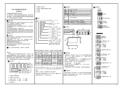
仪表失控时,请检查输出控制连线是否正确,外部负载有 否短路 \ 断路 \ 错线等导致仪表内部元件损坏,必要时可 打开仪表检查,输出端子铜箔 \ 输入输出保护电阻有否 损坏等.
HD8A 传感器检测控制仪表
使用手册
非常感谢您选择使用本公司的产品! 为了您的安全,在使用之前请仔细阅读本手册,若对本产品 有任何疑问,请与我们的销售员或您购买此仪表的经销商联 系。本手册如有改动恕不另行通知。
安全注意
为防触电或控制器失效,所有接线工作完成后方可供电,禁止带电 接线,为正确接线,不使用的端子,请勿接线。 清洁控制器前必须断开电后方可操作。 为防止控制器损坏或失效,请用仪表规定的电压供电,以免损坏本产 品或引起火灾。 为防止控制器失效或报废,严禁改动仪表。 输出继电器的使用寿命因开关容量和开关条件不同而存在很大差距, 因此必须考虑实际使用条件,请在额定负载和电气使用寿命内使用输 出继电器,如果输出继电器超过其使用寿命,触点可能会熔化或烧断, 有时会引起火灾。
96W × 48H × 80L
输入信号类型
可测量范围
mA V(AV/DV)
mV
Rt
0~1mA.0~10mA.4~20mA 0~5V.0~10V. 0~500V
0~10mV.±100mV 0~400Ω 0~10K Cu50 Cu100 -50~150℃
Pt
-200~650℃
Pr
20 段折线化输入处理
输入阻抗 ≤ 150Ω ≤ 200KΩ ≤ 2MΩ
参数设定
1 、报警参数设定:显示方式下,按 S E T 大于 3 秒可进入报警方式设定
一进二出
ASK-CLUX12S一进二出,HDMI1.3分配器操作指南1. 简介HDMI1.3分配放大系列是HDMI信号分配最先进的解决方案,这一系列的每个产品兼容HDMI1.3的规格,支持深度颜色的视频画面及无损耗的高度压缩的音频,带宽高达225MHz(6.75Gbps)除分配功能外,还有对信号放大均衡功能,因此具备高性能的音/视频输入输出,每路输出可达30米而且可以叠加使用。
2. 特点兼容HDMI1.3,HDCP1.1及DVI1.0可将画面达到1080P◎60HZ一路HDMI信号源输入,同时在两台HDMI显示器上显示HDCP键允许每路输出在接到显示器时独立工作将一路HDMI信号输出到两台显示器上时无衰减在使用HDMI/DVI转接器时支持DVI信号源和DVI显示支持DOLby Digital,DTS音频传输支持大多数的PC与HDTV规格的分辨率从VGA到UXGA,从480i到1080p在1080p的分辨率下对HDMI线的传输距离测试:输入距输出距离可达到30M/5.1CH兼容HDCP3. 操作按钮及功能前面板① HDMI 输出1,2:分别连接到两台HDMI显示器,显示同样的视频信号后面板① HDMI 输入:与信号源设备的HDMI或DVI输出接口相连② POWER:电源指示灯③电源插口:插入5V电源适配器4. 连接与安装5. 规格带宽:2.25Gbps(单连接)输入接口:1路HDMI母接口(A型) 输出接口:两路HDMI母接口电源:5V直流电外观尺寸:100W×147D×25H底盘材料:铝颜色:黑色操作温度:0℃~70℃。
- 1、下载文档前请自行甄别文档内容的完整性,平台不提供额外的编辑、内容补充、找答案等附加服务。
- 2、"仅部分预览"的文档,不可在线预览部分如存在完整性等问题,可反馈申请退款(可完整预览的文档不适用该条件!)。
- 3、如文档侵犯您的权益,请联系客服反馈,我们会尽快为您处理(人工客服工作时间:9:00-18:30)。
目录附录1 控制卡型录 (3)附录1.1控制卡选型 (3)附录1.2三代卡特色 (3)第一章概述 (3)1.1功能特点 (3)1.2运行环境 (4)第二章安装与卸载 (4)2.1安装 (4)2.2卸载 (5)第三章工具使用详解 (6)3.1软件主界面 (6)3.2标题栏 (6)3.3菜单栏 (6)3.3.1文件菜单 (6)3.3.2设置菜单 (7)3.3.3操作菜单 (9)3.3.4语言菜单: (9)3.3.5关于菜单: (10)3.4快捷方式栏 (10)3.5模拟显示屏 (11)3.6显示屏属性栏 (11)第四章显示屏节目创建流程 (12)4.1第一步:新建显示屏文件 (12)4.2第二步:新建节目 (14)4.3第三步:新建分区 (14)4.4第四步:节目制作完成 (15)第五章怎样显示不同内容 (16)5.1字幕显示 (16)5.2表格显示 (17)5.3图文显示 (18)5.4时间显示(万年历时间) (18)5.5表盘显示(模拟时钟) (19)5.5顺/倒时计显示 (20)5.6温度显示(需另购感应器) (21)第六章通信设置 (22)6.1串口线的做法 (22)6.2通信设置(串口) (23)6.3网线的做法 (24)6.4通信设置(网口) (25)6.4.1局域网单网络卡(HD-E3)通信 (25)6.4.2局域网多个网络卡(数个HD-E3)通信 (25)6.4.3局域网多个网络卡设置视频 (27)附录2 使用过程中的常用设置 (28)附录2.1控制卡如何远程升级 (28)附录2.2控制卡如何恢复出厂设置 (28)附录2.3控制卡如何测试显示屏 (29)附录2.4显示屏定时开关机 (29)附录2.5显示屏指定时间播放 (30)附录2.6字幕静止不动应该怎么设置 (30)附录1 控制卡型录附录1.1控制卡选型1:HD-S3-串口卡,控制范围32*1024(64个P10模组);2:HD-M3-串口卡,控制范围64*768/32*1536(96个P10模组);3:HD-Q3-U盘卡,控制范围64*768/32*1536(96个P10模组);4:HD-E3-网络卡,控制范围128*768/64*1536(192个P10模组);5:HD-U3-U盘卡,控制范围128*1280/64*2048(256个P10模组);6:HD-X3-U盘卡,控制范围256*1024/128*2048(512个P10模组);7:HD-G3-U盘卡,控制范围512*800/128*3072(800个P10模组);以上控制范围均为单色情况下,双色控制长度减半附录1.2三代卡特色采用全新高速32位MCU、扩大控制范围、性价比更高第一章概述1.1功能特点《HD2011》控制系统是2011年灰度科技有限公司应对条屏市场做出的较大的一次调整。
为方便客户选择,整合了部分重复的控制器,控制范围更新灵活,价格更适中,足以应对目前条屏做高、做长的趋势。
软件整体界面延续了操作简单、功能强大、易学易用的风格,支持文本、图文(JGP/BMP/GIF等)、时间、表盘、计时(正计时/倒计时)、温度、表格等,可满足不同场合的应用。
1.2运行环境操作系统:中英文(多语言)Windows98/2000/ME/XP/Win7/Vista等;硬件配置:无特殊要求第二章安装与卸载2.1安装《HD2011》软件安装很简单,操作如下:在您的光盘里找到文件HD2011_Setup.exe(或HD2011_Setup.RAR),双击该文件执行它。
将会进放软件安装向导,如下图按照屏幕提示(下一步),完成操作即可完成安装(请注意,如果运行环境为Win7或Vista时请装安装路径改为非系统盘)。
《HD2011》软件完成安装成功后,在【开始】/【程序】里会出现“HD2012”程序组,单击HD2012即可运行HD2012,同样您也可以点击桌面的HD2010.exe快捷方式进入操作界面。
2.2卸载《HD2011》软件包提供了完整的卸载功能,用户可以方便地删除《HD2011》里的所有文档、程序组和快捷方式。
用户可以在【开始】/【程序】/HD2011程序组里选择卸载HD2011即可完成软件的卸载操作。
第三章 工具使用详解3.1软件主界面打开《HD2011》软件主界面如下图3.2标题栏用于显示软件名称;3.3菜单栏包含 文件-设置-操作-语言-关于等选项3.3.1文件菜单包含新建、打开、保存、另存为、导出.hds 、退出等六个选项,标题栏菜单栏 快捷方式模拟屏 预览窗 模拟工具(放大减小/靠左靠右/左右翻页)多任务管理 亮度设置 定时关机 屏体参数通信设置端口 双击可打开通信设置如图:新建显示屏(Ctrl+N):用于新建一个显示屏,HD2011最多可管理255个显示屏;打开(Ctrl+O):用于打开最近使用显示屏文档;保存(Ctrl+S):用于保存当前的显示屏文件,默认保存在安装路径下的Proj文件夹内;另存为…(Ctrl+Alt+S):将当前显示屏文件另保存在指定的位置;导出.hds:用于导出源文件(可以确认内存是否超界);退出(E):关闭HD2011软件。
3.3.2设置菜单包含屏参设置、通信设置、系统设置如图屏参设置(F5):用于设置控制卡和显示屏的基本参数,如图;通信设置(F6):用于设置控制卡与电脑之间的通信,如图;系统设置(F6):用于设置系统参数(不建议更改)。
3.3.3操作菜单包含发送项目、集群发送、清除显示数据、导出到U盘、IP管理工具、时间设置、亮度设置、定时开关机、显示屏测试、固件更新。
如图发送项目:用于发送当前显示屏文件;集群发送:网络卡专用,用于发送多个显示屏文件;清除显示数据:清空控制卡存储器内信息(恢复出厂设置);导出到U盘:把数据导放到U盘,进行更新;IP管理工具:网络卡专用,用于分配不同网络卡的IP地址;时间设置:设置控制卡时间;定时开关机:设定定时开关机时间;显示屏测试:软件测试显示屏;固件更新:用于远程升级控制卡。
3.3.4语言菜单:包含中文简体、中文繁体、英语、俄语、土耳其语、伊朗语等六用语言,用于不同语言的切换;3.3.5关于菜单:用于查看HD2011软件的版本号;3.4快捷方式栏包含节目、字幕、图文、时间、表盘、计时、温度、删除、发送、导出、校时、预览等工具,如图:节目:用于新建一个节目(节目为显示屏的次一级目录);字幕:用于新建一个字幕区域(可编辑文字、表格等内容);图文:用于新建一个图文区域(可插入图片及超文本等内容);时间:新建一个时间区域,用于显示系统时间(万年历模式);表盘:新建一个时间区域,用于显示系统时间(模拟时钟形式);计时:用于新建一个倒/正计时区域(可显示正/倒计时);温度:新建一个温度区域,用于显示当前环境温度(需加温度传感器模块);删除:用于删除选中的项目;发送:用于发送当前显示屏文件;导出:U盘卡专用,当前显示文件保存到U盘内(U盘更新);校时:校正系统时间(调整控制卡时钟与电脑同步);预览:预览当前的节目(注意,只有选中一个节目才可以预览);3.5模拟显示屏模拟屏预览窗模拟工具(放大减小/靠左靠右/左右翻页)请注意:在模拟显示屏的下面有一行工具栏,合理利用可以帮你更方便的编辑显示屏文件(包含:放大/缩小模拟窗口、当前区域左右移动、显示屏内容翻页等工具)3.6显示屏属性栏此栏可以进行亮度设置/定时开关机设置等亮度设置定时关机亮度设置:三种模式(不建议改动);定时开关机:用于设置定时开关机时间;第四章显示屏节目创建流程4.1第一步:新建显示屏文件(第一级内容)方法:单击文件-新建显示屏(密码是168),弹出设置页面如下:1.模块选择:选择你的控制卡型号,选择完成后点击下一步;2.基本设置,主要用来设置数据极性、颜色、OE极性、屏宽、屏高、扫描方式和是否使用138译码器3.设置之前需要先了解各参数的正确属性,错误的参数会导制显示错误;4.常见故障:数据极性设置错误,会导制红底黑字;138译码器设置错误将会导制不显示或错显示;颜色设置错误,可能会导制屏高或屏宽跳回;OE极性设置错误会出现亮度不均,显示屏有数行高亮,数行暗亮;扫描方式设置错误的话,会显示乱码;5.高级设置:用于设置完成后,点击完成,完成一个显示屏的建立(我们案例是用的常规P10的显示屏来设置的)如图(可设置亮度及定时开关机,使用时请正确设置)新建的第一个显示屏亮度设置定时关机4.2第二步:新建节目(第二级内容,一个显示屏可建20个节目)方法:单击快捷栏的节目按钮(前题是先选中一个显示屏)如图:新建节目如下图(包含边框-分时段设置等选项)注意:20个节目每个节目都可以设置不同的属性,这些属性包括播放模式、边框设置(超过200种)和播放时间(指定时间段)4.3第三步:新建分区(第三级内容,每个节目可设置3个或5个分区)方法:先选中节目后,单击字幕、图文、时间、表盘、计时、温度等,新建不同类型分区,如下图新建节目在这里显示最多可建20个节目这里用来设置固定时间播放这里用来设置节目边框按星期播放勾中表示显示4.4第四步:节目制作完成经过上面的第一、二、三等三个步骤,我们就完成了一个显示屏文件的创建,如果我们需要创建多个节目的话,只需重复上面的第二、三个步骤创建多个节目即可(可以在同一个显示屏内播放);如果需要用一个软件控制多个显示屏则需要创建多个显示屏文件,重复第一、二、三,三个步骤即可;节目制作完成后,可以存盘(默认是保存于安装路径下的Proj 文件夹里,也可以通过文件菜单保存于指定目录)。
通过预览可以实时查看每个节目的动态图,进行显示方式设置,满意的话可以通过发送按钮,将内容发到到显示屏上。
区域在这里显示,单击可选择不同区域不同区域位置不可生重复文本内容在这里输入,选中文字可更改字体/大小/颜色超过40种显示方式30种退出方式可选速度1ms 为最快设置坐标区域 坐标不能重叠第五章 怎样显示不同内容5.1字幕显示纯文字内容显示,我们用字幕区域就可以达到要求 步骤:参考4.1及4.2的内容,创建显示屏-节目; 单击字幕,出现字幕区域(可自由设置坐标、长、宽)注意:单纯的显示文字,我们建议在字幕区域内完成(最简单的设置),HD2011的软件编辑器功能强大,可对单个文字进行改动,可对左右居中,上下居中,字间距,行间距等进行编辑;字幕区域选择显示及退出方式(超过40种可选)速度设置1为最快这里输入内容选中文字可调整字体/字体大小/颜色怎么样在显示屏上显示表格?步骤如下:步骤:参考4.1及4.2的内容,创建显示屏-节目;单击字幕,出现字幕区域(可自由设置坐标、长、宽),可以看到在文本输入框的右方有一个编辑器的图标如图点击编辑器点击表格-新建表格完成设置即可表格完成后关掉编辑器即可完成后表格的预览情况如果想在显示屏上显示LOGO 或图片(仅限JPG ,BMP ,PNG ,GIF 等格式),应该怎么设置呢?步骤如下步骤:参考4.1及4.2的内容,创建显示屏-节目;单击图文,出现图文区域(可自由设置坐标、长、宽),在下方的文件列表位置添加要显示的图片即可,如下图5.4时间显示(万年历时间)显示屏的时间显示跟字幕、图文类似,单击时间区域即可,步骤如下图文区域图片的添加删除在这里进行选择图片的显示及退出方式步骤:参考4.1及4.2的内容,创建显示屏-节目;单击时间,出现时间区域(可自由设置坐标、长、宽),设置比较简单,位置设置好即可,如下图万年历时间预览单行多行显示选择时间显示格式时间区域坐标设置5.5表盘显示(模拟时钟)显示屏的表盘显示跟字幕、图文类似,单击时间区域即可,步骤如下步骤:参考4.1及4.2的内容,创建显示屏-节目;单击表盘,出现表盘区域(可自由设置坐标、长、宽),设置比较简单,位置设置好即可,如下图5.5顺/倒时计显示显示屏显示正/倒计时步骤:参考4.1及4.2的内容,创建显示屏-节目;单击计时出现计时区域(可自由设置坐标、长、宽)如图时间区域坐标设置 调宽度和颜色添加背景表盘内容预览5.6温度显示(需另购感应器)显示屏显示当前环境温度步骤:参考4.1及4.2的内容,创建显示屏-节目;单击温度出现温度区域(可自由设置坐标、长、宽)如图倒计时内容预览倒计时单位参数在此位置设置倒/正计时窗口输入背景温度内容预览参数在此位置设置窗口输入背景通过以上 5.1-5.6,可以了解到我们的软件可设置多功能,多区域的内容,足以满足显示屏在各个场景的应用。
