印度一水下航行器玛雅号技术规格
HAKO产品说明书

PRODUCTION VISESVisesIntroduction to Design ...........................................66–67VMC/HMC Solutions ............................................68–69Ball Lock® Mounting System ...............................70–71Production Vises4" (100 mm) Production Vises ................................72–736" (150 mm) Production Vises .................................74–75Self Centering Vises .................................................764" (100 mm) ................................................................76–776" (150 mm) ................................................................78–79Accessories ......................................................................79Production Vise Columns 4" (100 mm) Production Vise4 Sided ...........................................................................803 Sided ...........................................................................816" (150 mm) Production Vise4 Sided ...........................................................................823 Sided ...........................................................................8312 Station Hex .................................................................8412 & 16 Station Multi Quads ..................................85–86Hydraulic Production Vises .....................................874" (100 mm) ...............................................................88–896" (150 mm) ...............................................................89–90Hydraulic Vise Columns ...........................................914" (100 mm) 4 sided ........................................................924" (100 mm) 3 sided ........................................................936" (150 mm) 4 sided ........................................................946" (150 mm) 3 sided ........................................................95Column Subplates ..........................................................96Hydraulic Vise Accessories......................................97–98Vise Accessories ...............................................99–104Jaw Selections ..................................................99–101Ball Lock® Shanks/Plates .....................................102–103Sine Fixture Keys/T-Slot Nuts .....................................104Cast Iron Shop Vises ......................................105–106Bock Quick Change FixturingIntroduction ..................................................................107System Overview .................................................108–109Twin Vises ........................................................................110Jaw System .....................................................................111 Twin Vise Data ................................................................112Locator Plates .................................................................113DexLoc™ Locator Pins ...................................................113 Mono-Quad System (114)5-Axis Production VisesIntroduction ...................................................................115Self Centering .................................................................116Jaws /Accessories ................................................117–118Fixed .................................................................................119Jaws/Accessories .......................................................120Quick Clamping Block .................................................121Super Compact Clamp .................................................122Jaws/Accessories ...............................................123–124Vise with Reversible and Interchangeable Inserts ...125Jaws/Accessories .......................................................125Pallet Clamps .. (126)P R O D U C T I O N V I S E SWORKHOLDING SOLUTIONS GROUPPRODUCTION VISESJergens Production Vise SystemFastest Quick Change Jaw SystemMaximum Holding Power• Jaws machined to the contour of your workpiece maximizing holding force.6" (150mm) MonoQuad4" (100mm) MonoQuad• Quick change reverseable soft jaws • Single station adapter plate included• Multiple base designs to meet any requirementDual Station VisesSelf-Centering VisesWORKHOLDING SOLUTIONS GROUPPRODUCTION VISESJergens Production VisesMachine “Pockets” into the vise jaws, in the shape of your workpiece.Benefit: Reduce set-up times and parts change overMultiple mounting base configurations Fully sealed lead screw assemblyBenefit: Lower maintenance Rigid construction with hardened and ground stainless steel railsBenefit: High accuracy and repeatabilityChip and fluid flow through baseBenefit: Easier to keep clean, no more cloggingWORKHOLDING SOLUTIONS GROUPPRODUCTION VISESVertical Machine SolutionsHydraulic Vise Pages 88–90Innovative compact design. Reduced set-up time.Internal Slide Assembly with Hydraulic Clamping Cylinder.Universal Base Production Vises Pages 73 & 75The mounting flange has slotted holes to allow Ball Lock ® Base Production Vises Pages 72 & 74The mounting flange is cut into a jigsaw pattern to allowvises to nest closely together. Designed for use with Jergens Ball Lock ®Mounting System.5-Axis production vises and accessories rigidly clamp parts without obstructing access to multiple part faces.Self Centering Vises (3 Base Styles)Pages 76–79Self-Centering vises provide quick, simple fixturing for concentric machining of different sized workpieces.Narrow Base Production Vises Pages 73 & 75The small footprint allows maximum density of vises on your Bock Brand Quick Change System Pages 107–114Bock Brand vises combine with alpha-numeric locator plates Indexer Systems Page 81Indexer solutions can be customized to yourrequirements. Choose either three or four sided columns.WORKHOLDING SOLUTIONS GROUPPRODUCTION VISES Horizontal Machine Solutions6-Sided Production Vise ColumnsPage 84Increase the number of parts per load, while maintaining a small footprint. Available with bases to fit directly onto 4-Sided Production Vise Multi-Columns Pages 85 & 86Multiple columns mounted on a single base provide 12 or 163-Sided Production Vise ColumnsPages 81 & 83For machining 3 faces of production parts on HMC's. Largespindle noses can access the workpiece.240° workpiece accessibility.Multi-Vise FixturesPages 73, 75, 77, 79 & 89T o maximize productivity, mount multiple narrow body visesonto a single fixture plate. Mount the fixture plate onto thetombstones with the Jergens Ball LockWORKHOLDING SOLUTIONS GROUP PRODUCTION VISESSystem accurately positionsThe Ball Lock System securely holds fixtureplates to subplates with up to 20,000 lbs (88kN)of hold-down force per shank.Ball Lock® Fixture Mounting System forThe Ball Lock® Mounting System provides a method of quickly and accurately locating fixtures onto machine tables. The Ball Lock Commonly Asked QuestionsQ. What is the Ball Lock®Mounting System?It is a means of locating and lockingtwo flat surfaces together, normally afixture plate to a sub-plate.Q. How does it lock?A. Inside the shank are three balls thatexpand into a tapered groove in thereceiver bushing. This action drawsthe plates together. The locking ballsare activated by turning a setscrew inthe head of the shank, which pushesWORKHOLDING SOLUTIONS GROUPPRODUCTION VISESUnmatched Setup Speedand Workholding FlexibilityQ. Is there a preferable location for System repeatability is improvedif the liners are located at opposite corners of a rectangular fixture plate. For consistency, we recommend locating the liner bushings at top left Q. What are the advantages of using with ¾" (18mm) of thread engagementrequires 10 turns to lock. On CNCmachines, the repeatability of fixturelocations makes indicating of thefixture unnecessary.Q. How do I recess the fixtureplatefor a clear surface ?A. Counterbore the fixture plate to adiameter large enough to allow easyQ. What if my plate is thinner thanthe recommended thickness?A. By adjusting the depth of thecounterbore for the receiver bushingin the subplate, you can still use theBall Lockquestions on this type of application,please call 1-877-426-2504.Q. Can I use the shanks in a heated0.38[10]0.96[24]3.438[87.5]1.683.00[73]1.22[30][190]7.50WORKHOLDING SOLUTIONS GROUPPRODUCTION VISESProduction Vises – 4" (100mm)Ball Lock ShankShankPart No.Wt.Part No.SizeMetric17/32" (4) Plcs [13.5]Slotted Mounting Holes:3.13[80]2.50[63.5]6.00[150]Mounting Holes (2) Plcs:17/32"[13.5]WORKHOLDING SOLUTIONS GROUPPRODUCTION VISESProduction Vises – 4" (100mm)traditional strap clamps. The narrow base has 2 locating holes for 12mm -slots shown on page 104. Recessed machine tables, tombstones, or columns. Maximize flexibility by utilizing0.50[12]4.50[114]4.00[100]10.00[248] 1.45[38]0.96[24]WORKHOLDING SOLUTIONS GROUPPRODUCTION VISESProduction Vises – 6" (150mm)MetricBall Lock ShankShank Part No.Wt.Part No.Size1.125[28]2.952[75]4.921[125]7.874[200]6.000[150]Mounting Holes:M10 x 1.5 T ap (6) Plcs2.50[63.5]3.875[100]7.874[200]Locating Holes:.6255 (4) PlcsFor Sine Fixture KeysWORKHOLDING SOLUTIONS GROUPProduction Vises – 6" (150mm)is easily mounted directly to machine tool tables. Slotted mounting holes will match almost any table slot pattern. can be mounted as a stand-alone vise or mounted to a fixture plate. The slim design allows a high density of vises on machine tables, tombstones, or columns. Maximize flexibility by utilizing the Jergens1.22"(31.0)ED MTG. HOLES3.370"(85.60)±0.001"(0.03)WORKHOLDING SOLUTIONS GROUPSelf-Centering Precision Production Vises• Shown in Universal Base, also available in Narrow Bases and Ball Lock Part Number Wt. (lbs)49471SC38WORKHOLDING SOLUTIONS GROUPSelf-Centering Vises – 4" (100mm)12"6"WORKHOLDING SOLUTIONS GROUP Self-Centering Vises – 6" (150mm)12"6"50m m 12" (300mm )WORKHOLDING SOLUTIONS GROUPSelf-Centering Vises – 6" (150mm)Part No.49442SC*Jergens Standard Jaws fully compatible, see complete selection on page o order Jergens Production Vise Jaws with Adjustable Gib Screw, use standard jaw part no. followed by "SC".WORKHOLDING SOLUTIONS GROUP Production Vise Columns – 4" (100mm)QWORKHOLDING SOLUTIONS GROUPcan be mounted onto most any indexer. Columns can be attached directly to an indexer or become Jergens Technical Service for help designing Production Vise Columns – 4" (100mm)Mounting Wt. Ball Lock Shank Pattern 2* (lbs) Part No. Sizen/a 125 49602 20mm x 1"100mm 115 — —Mounting Wt. Ball Lock Shank Tri-column design allows upWORKHOLDING SOLUTIONS GROUP Production Vise Columns – 6" (150mm)QWORKHOLDING SOLUTIONS GROUPProduction Vise Columns – 6" (150mm)Mounting Wt. Ball Lock Shank Pattern 2* (lbs) Part No. Size252 49602 20mm x 1"266 49612 25mm x 1"100mm 240——Tri-column design allows upJBall Lock Mtg. PatternBall Lock Mtg. PatternWORKHOLDING SOLUTIONS GROUPProduction Vise ColumnsQK Ball Lock Mtg. PatternQKBall Lock Mtg. PatternWORKHOLDING SOLUTIONS GROUPPRODUCTION VISESProduction Vise ColumnsMtg. PatternK QQKBall Lock Mtg. PatternWORKHOLDING SOLUTIONS GROUPPRODUCTION VISESProduction Vise ColumnsWORKHOLDING SOLUTIONS GROUPPRODUCTION VISESHydraulic Production Vises• Innovative compact design • Internal hydraulics• 4,700 lbs (2,100 Kg) clamping force • Operates on lower input pressure • Fully machinable jaws• Fastest quick-change jaw system • Hardened stainless steel wear rails •Easy-Flow ™base designJergens hydraulic vises are available in 3 different base configurations. They offer the same unique features as Jergens manual vises.Technical Specifications:Hydraulic Clamping Stroke: 1/4" (6.3mm)Operating Volume: 0.4 Cu In (6.7 cm 3)Maximum Input Pressure: 4000 P .S.I. (275 bar)Minimum Input Pressure: 500 P .S.I. (35 bar)Input Port: #4 SAE (7/16-20 UNF-2B)Clamping Force (lbs) = Input Pressure x 1.19Clamping Force (Kg) = Input Pressure Bars x 7.67Operation:Using the Jergens Hydraulic Vise handle part number 49445, tighten vise jaws so the workpieces touch the fixed jaw. Next, turn the handle back 1/2 turn and activate the hydraulic cylinder. Hydraulic Power Sources AvailableClamping ForceInput PressureClamping ForcePSIBarslbskgf500 35 595 268 1,000 70 1,190 5376.0012.002.50[63.5]3.125[80] 6.00[150]17/32" (4) Plcs [13.5]Slotted Mounting Holes:Mounting Holes :17/32" (2) Plcs [13.5]WORKHOLDING SOLUTIONS GROUPPRODUCTION VISESHydraulic Production Vises – 4" (100mm)Mounting Holes:ap (6) PlcsMOUNTING HOLES (6) Plcs:3.938[100]LOCATING HOLES:.6255 (6) PlcsWORKHOLDING SOLUTIONS GROUPPRODUCTION VISESHydraulic Production Vises – 4" (100mm)Part Wt. N umber lbs/Kg49487 30/14Part Wt. N umber lbs/KgPart Wt.PRODUCTION VISESWORKHOLDING SOLUTIONS GROUP Hydraulic Production Vises – 6" (150mm)12.006.00PRODUCTION VISES WORKHOLDING SOLUTIONS GROUPHydraulic Vise Column(150mm) sizes,Fully Machinable and ReversibleMore workholding flexibility per jaw set.Hydraulic Vise Column Kits Include:Shown with base forSee page 98 for Air PoweredHydraulic PumpPRODUCTION VISESWORKHOLDING SOLUTIONS GROUP Hydraulic Vise Tooling Columns – 4" (100mm)PRODUCTION VISES WORKHOLDING SOLUTIONS GROUPHydraulic Vise Tooling ColumnsPRODUCTION VISESWORKHOLDING SOLUTIONS GROUP Hydraulic Vise Tooling Columns – 6" (150mm)Hydraulic Vise Tooling ColumnsHydraulic Vise Tooling Columns Standard Subplates35°TANK PRESSURE PORT1/4 NPT PORTS3.411.0260.091.0662.750.650.9380.375 AREA FOR TANK LINE LOCATION0.60 AREA FOR PRESSURE LINE LOCATION2.752 3/8"M5 X 0.8 TAP THRU (4) PLACES7/32 DRILL THRU (4) PLACESPTPORTPatent No. 3839866Hydraulic Production Vise AccessoriesPart Number61725HandlePart Number49445Handle for Hydraulic Vises, 4" Rotary Hydraulic UnionDual Passage, Ports 1/4 NPTPressure (psi) Bars Torque (in. lbs) Part Number61755 Performance Curve*(0.655)1000 2000 3000 4000 5000 (69) (138) (207) (276) (345)OUTPUT PRESSURE, PSI (BAR)Part Number61759Hydraulic Production Vise AccessoriesKit Includes61755 36:1 Pump61643 Remote four-way zero-leakageLow Pressure Air HoseHose I.D.1/4" 3/8" 1/2"HosePart Number 61106 61108 61110FittingPart Number 61107 61109 61111Hydraulic HoseHigh pressure hose is supplied assembled and to lengths indicated. Lengths are measured from end of coupling to end of coupling. Hose is 3/8" ID and available in 4000 psi or 7000 psi rating. 3/8" female tubing fittings on each end.N ipple1/8 NPT Male 619501/4 NPT Male 61905 619511/4 NPT Female61954 Air couplers have checks on sleeves only.Adapter for BSP1/4 Male NPT 1/4 NPT x 1/4 T 1/4 Female BSP 60221Adapters & ElbowsJergens Production Vise SystemThe clamping system Completely sealed lead screw Hard coated base made of high-strength, light-weight, aluminum extrusion. Guideway Rails made of hardened stainless steel.Aluminum jaws can be completely milled, therefore Aluminum or steel jaws suitable for milling:Extra Wide Jaws Full Face Vise PlateDual Station with Hard JawSingle Workpiece with Hard JawsProduction Vise JawsQuick Change Fixture PlateProduction Vise Accessoriesinclude two moveable jaws and one fixed jaw.Vise Conversion PlatesVise HandlesHard Jaw Carriers With Steel Inserts*Part No.Vise Size49442 4"/100mm Machinable Soft Jaws(Standard Sets included with Vises)Vise Work StopClearance holes for holddown (2) PlcsClearance holefor holddownStandard ShankJigsaw Fixture PlateMultiple Vise Fixture PlateProduction Vise Ball Lock ®Accessories – InchShank49601 49601-S 49602 49602-S 49611 49611-S49612 49612-SProduction Vise Ball Lock® Accessories – MetricJigsaw Fixture PlateClearance holefor holddownStandardShank Multiple Vise Fixture PlateClearance holes forholddown (2) PlcsProduction Vise Accessories Locate subplates or fixture plates to Tmachine tables. Available in inch sizes for 1/2"to 7/8" slots, and in metric sizes for 12mm to22mm slots.T-Slot NutsWORKHOLDING SOLUTIONS GROUPCast Iron Shop VisesCharacteristicsMade of close grained high tensile cast iron. Jaws ground and Hardened 55±3 HRC. Swivel base provided with positive locking and adjustable through 360°. Adjusts work piece to its center. Opposite threads for quick and accurate centering.CharacteristicsMade of close grained hightensile cast iron. Jaws ground and Hardened 55±3 HRC. Adjusts workpiece to its center. Opposite threads for quick and accurate centering. This is a low profile vise.T echnical DataPart Jaw Width Jaw Opening N umber Inch mm Inch mm Inch mm Inch mm Inch mm Inch mm 110080 2 50 2 50 110081 4 100 4 100 T echnical DataPartJaw Width Jaw OpeningNumber Inch mm Inch mm Inch mm Inch mm Inch mm Inch mm 110085 3 75 5 127 110086 4 100 4 100WORKHOLDING SOLUTIONS GROUPCharacteristicsManufactured from close grained high tensile cast iron. Swivel is full 360°. This is very useful for heavy duty milling jobs. Vise is low height for maximum clearances. Jaws are fully ground and precision with parallelism of 0.0012 (30 microns) the hardness of jaws is 55±33 HRC.T echnical DataPart Jaw Width Jaw Opening Jaw Depth N umber Inch mm Inch mm Inch mm Inch mm Inch mm Inch mm T echnical DataPartJaw Width Jaw Opening Jaw DepthNumber Inch mm Inch mm Inch mm Inch mm Inch mm Inch mm 110250 6 150 7 1/2 188 1 1/2 CharacteristicsManufactured from graded cast iron and precisionground. These vises have a needle bearing thrust collar. Vise jaws are in pairs and replaceable.Cast Iron Shop VisesMilling Machine Vises with Swivel Base (Heavy Duty)Machine VisesWORKHOLDING SOLUTIONS GROUP JERGENS-BOCK QUICK CHANGE S YS TEMFASTPRODUCTIVE by reducing spindle down-time to aminimum. The combination of short setup times, theability to move setups away from the machine andfast loading keeps your spindle cutting, not waiting.WORKHOLDING SOLUTIONS GROUPJERGENS -BOCK QUICK CHANGE S YS TEMwin Vise is the key component of the complete BockWorkholding system. A variety of body styles made from high-strength aluminum, ground steel guides, snap-on quick-change machinable aluminum jaws and a solid clamping screw and third hand mechanism System OverviewBock Locator Plate SystemBock Locator Plates are a great platform to quickly and accurately mount your T win Vises in a number of different positions. Locator/mounting holes with alpha-numeric identifiers and Bock’s DexLoc™ double-expanding locators give you +/- .0005" repeatability.DexLoc ™Locator PinsPatented DexLoc™ double-expanding locator pins allow for fast and accurate location of twin vises on locator plates.WORKHOLDING SOLUTIONS GROUP JERGENS-BOCK QUICK CHANGE S YS TEMHard-coated high-strength aluminum base for lighter WORKHOLDING SOLUTIONS GROUPJERGENS-BOCK QUICK CHANGE S YS TEMStraight basefor use on Bock Locator Plates or with toe clamps Slim-LineStandard interlockingGenerous cut-outs to prevent chip and coolant accumulationBock Twin Vise SystemThree different basestyles for your specificmounting needsWORKHOLDING SOLUTIONS GROUP JERGENS-BOCK QUICK CHANGE S YS TEM Bock Jaw SystemBock Machinable Jaws are made from high-strength aircraft grade anodized aluminum.Once machined to hold a specific part they become quick-change dedicated fixtures ideal for holding even complex shapes.STANDARD JAWS snap on and off in QUICK CHANGEFACE PLATEScan be convertedTALL JAWSto hold larger parts.123WORKHOLDING SOLUTIONS GROUP JERGENS-BOCK QUICK CHANGE S YS TEMBock Twin VisesScrew-on guideways made from hardened steelThird-hand function for fast sequential loading of partsExact positioning of center jaw using locator pins; removing center jaws allows the holding of one single large partAluminum jaws can be milled out to meet each part’s holding and locating requirements.Generous cut-outs to prevent chip and coolant accumulationStandard InterlockingStraight BaseSlim-LineWORKHOLDING SOLUTIONS GROUP JERGENS-BOCK QUICK CHANGE S YS TEM Bock Brand Locator Plate SystemBock Brand Locator PlatesDexLoc™ Locator PinsTo order DexLocWORKHOLDING SOLUTIONS GROUP JERGENS-BOCK QUICK CHANGE S YS TEMBock Mono-Quad System。
《钢质海船入级规范》

修改通月 1 日
北京
目录
第 1 篇 入级规则............................................................................................................................. 4 第 5 章 建造后检验 ............................................................................................................... 4 第 2 节 检验种类与周期 ................................................................................................. 4 第 9 节 机械检验 ............................................................................................................. 4 第 11 节 船底外部与有关项目检验 ............................................................................... 4 第 14 节 不在 CCS 检验下建造船舶的初次入级检验 ................................................. 4 附录 21 延长干坞检验间隔期指南—干坞检验展期(EDD)计划 .......................... 5 第 2 篇 船体.....................
海上巨人号

海上巨人号
-
目录
01.简介 03.经历
02.特征 04.意上巨人"号(又名"亚勒维京"号),于1981年在日本横须贺港下水,期间风雨经历了35年 。2010年1月4日在印度拆卸,他一直保持著两项世界纪录,全船长458.45米,不但超出世 界最大集装箱船、马士基航运的"爱玛?马士基"号60多米,比中环国金二期大厦还要高20 米
海上巨人号
贰
最早订做的希腊船东在船只完工前破产,于是在1979年把船厂将船转卖给当时的香港船王 ──董浩云,由原来的Porthos号改名为「海上巨人」号
海上巨人号
叁
1981年下水后,「海上巨人」号遇到两伊战争,载运伊朗或其他阿拉伯国家生产原油的船 只都成为伊拉克袭击的目标,「海上巨人」号也未能幸免,1988年,她被伊拉克飞鱼导弹 击中,船身严重毁损,在伊朗卡克岛附近海域沉没
-
谢谢
特征
载重吨42万吨,这艘 船于1979年启用, 1980年它的中部被延 长了80米,成为56.4 万吨。直到2009为止 它依然是世界上最大 的油轮,长458.45米 ,宽68.9米,吃水 24.5米
海上巨人号
海上巨人号
经历
壹 1975年由日本横须贺住友重机追浜造船厂建造的超大型油轮,从建造到拆卸的35年间,先 后拥有6个名字
海上巨人号
肆
战争结束后,船只被修复,先被挪威的海运公司诺曼国际买入,更名为「快乐巨人」号, 后于1991年又转售给挪威亚勒海运,易名为「亚勒维京」号,并在之后的13年一直为这家 公司服务,其间再与挪威船东有业务往来的香港华林集团有限公司管理,直至2004年再次 被转售给新加坡籍的第一奥森油轮公司,并被改装成海上浮式原油储卸系统(FSO),改名 为「诺克.耐维斯」号
MGE Galaxy 7000

所有这些测量值来自对超过 200 台设备的生产线 ATE 统计。
系统 160 kVA 200 kVA 250 kVA 300 kVA 400 kVA 500 kVA
25% 负载 87.0 90.0 89.7 90.5 92.2 91.4
50% 负载 92.0 93.0 93.2 93.5 94.1 94.3
图纸 ............................................................... 17
MGE Galaxy 7000 单机系统 ......................................... 18
990–3887A-037
MGE™ Galaxy™ 7000 技术规格
990–3887A-037
技术数据
型号列表
MGE™ Galaxy™ 7000 UPS 可提供以下型号:
• MGE™ Galaxy™ 7000 160 kVA 380/400/415 V • MGE™ Galaxy™ 7000 200 kVA 380/400/415 V • MGE™ Galaxy™ 7000 250 kVA 380/400/415 V • MGE™ Galaxy™ 7000 300 kVA 380/400/415 V • MGE™ Galaxy™ 7000 400 kVA 380/400/415 V • MGE™ Galaxy™ 7000 500 kVA 380/400/415 V
建议的过流保护措施 .............................................. 11 建议的上行和下行保护措施 ......................................... 11 电池保护...................................................... 12 建议的剩余电流保护措施 .......................................... 12
黑翼飞行模拟器用户手册说明书

IntroductionThe Blackwing BW 635RG is an ultralight two-seater aeroplane designed for recreational flying and training purposes. It features a sleek and modern design, with a composite airframe and a low-wing configuration. The Blackwing has a cruising speed of up to 120 knots and a range of approximately 700 nautical miles, making it suitable for both short and long-distance flights. The cockpit is equipped with state-of-the-art avionics, including a glass cockpit display and an autopilot system. The Blackwing is also known for its superior handling and stability, making it a popular choice among flying enthusiasts and flight schools. The BW 635RG is powered by the venerable Rotax 915 iS engine.Development Credits:Mal Cartwright Product LeadRuss White3D Modelling, Interior and Exterior TexturingJack Lavigne IntegrationHarry Stringer AnimationPropAir Flight Model and SystemsJordan Gough ManualWith special thanks to our Beta Testers:Rob Abernathy John BurgessNick Cooper John DowMatt McGee Darryl WightmanTable of ContentsIntroduction (2)Development Credits: (2)With special thanks to our Beta Testers: (2)Table of Contents (3)Notes on Hardware (4)Overview (5)Aircraft Limitations (6)Airspeed Limitations (6)Engine Limitations (6)Operating Conditions (6)Fuel (7)Other Limitations (7)Emergency Procedures (8)Engine Failure on the Take-off Roll (8)Engine Failure after Take-off (8)Glide Performance (8)Emergency Landing (9)Spin Recovery (9)Normal Procedures (10)Before Starting Engine (10)Starting Engine (10)Before Taxiing (11)Taxiing (11)Engine Runup (11)Before Take-off (11)Take-Off (12)Initial Climb (12)Cruise Climb (12)Cruise (12)Landing (13)Balked Landing (13)After Landing (13)Securing Aircraft (14)Basic Performance (15)Stall Speeds (15)Take-Off Performance (15)Landing Performance (16)Systems Description (17)Instrument Panel Layout (17)Switch Logic and Electrical System (18)Master Switch (18)Fuel Pump Switch (19)LAND/TAXI Switch (19)Strobe/Nav Switch (19)Electrical System Diagram (20)Engine (21)Propeller (21)Fuel (21)Notes on HardwareDue to the unusual 3-position switches in this aircraft, conventional hardware 2position toggle switches (eg. strobe or nav light switches) cannot be translated tothe single 3-position switch which combine these.Additionally, as this aircraft utilises a single level power control (throttle), conventional throttle/prop/mixture hardware may interfere with the function of this system, and not work as intended. It is recommended to place your propeller and mixture levers in the IDLE position, and not move them while the engine is running.OverviewThe Orbx BW 635RG has been developed using official documentation and Computer Aided Design (CAD) resources from Blackwing Sweden. As a result, the aeroplane has been created through masterful modelling, texturing, systems integration, and flight model development.Figure 1 – Aircraft 3-viewAircraft DimensionsLength 6.6m Height 2.2m Wingspan8.4mWeightsBasic Empty Weight 375kg Maximum Take-off Weight 600kg Maximum Fuel Capacity (Litres)130LThe content in this manual and the operation of the BW 635RG in Microsoft Flight Simulator strictly must not be used as reference material in any form for operating the real aircraft.Aircraft LimitationsAirspeed LimitationsAirspeed Description Airspeed (KIAS) RemarksVne Never Exceed Speed 157 Must not exceed this speed in any operation.Va Manoeuvring Speed 109 If full or abrupt control deflection is made, the airframe may be overstressed.Vfe1 Max flap extended speed20 degrees90 Maximum speed for flaps 20°Vfe2 Max flap extended speed35-45 degrees 70 Maximum speed for flaps 35-45°Vlo Maximum landing gearoperating speed 70Do not extended or retract the landing gearabove this speed.Vle Maximum landing gear extended speed 90 Do not exceed this speed with the landing gearalready down.Vs0 Stall speed flaps/gearextended 38 Stall speed with gear down/flaps >0° and in level flight at MTOWVs1 Stall speed clean 49 Stall speed flaps retracted, gear up and in level flight at MTOWEngine LimitationsEngineEngine Manufacturer Rotax Engine Model Rotax 915 iSMaximum Power Take-off (Max 5 min.) 141 hp Continuous 135 hpMaximum RPM Take-off (Max 5 min.) 5800 Continuous 5500Critical Altitude 15000ft AMSL Maximum OperatingAltitude23000ft AMSL Operating ConditionsAerobatic manoeuvres, flight in IFR conditionsand flights in icing conditions are prohibited inthis aircraft.FuelFuel TanksLeft Right Litres US Gal Litres US GalTotal Fuel in Tank 67.5 17.8 62.5 16.5Unusable Fuel 2.5 0.7 2.5 0.7 Total Useable Fuel in Tanks 66.5 17.6 61.5 16.2Other LimitationsMaximum demonstrated crosswind for the BW 635RG is 20 knots.Emergency ProceduresNote: The following procedures have been modified to be suitable for simulation. It does not cover emergencies that are a) not simulated and b) not reasonable. Checklist items from the real procedures have been omitted and these procedures must not under any circumstances be used for training purposes.Engine Failure on the Take-off RollThrottle: IDLEIgnition: OFFFuel Pump: MAIN (DOWN POS)Brakes: APPLYWhen stopped: SECURE AIRCRAFTEngine Failure after Take-offNose: IMMEDIATELY LOWERAirspeed: 65 KNOTSLanding Area: DETERMINE WITHIN 30° OF NOSEFlaps: USE AS REQUIREDLanding Gear: USE DESCRETIONFuel Selector: OFFIgnition: OFFMaster Switch: OFFGlide PerformanceThe BW 635RG, the approximate performance for a glide is 65 KIAS which willgive approximately a 545ft/min rate of descent in the clean configuration.Glide performance will degrade significantly on extension of flaps and landinggear.Emergency LandingAirspeed: 65 KIASField: PICK BEST OPTIONLanding Gear: USE DISCRETION DEPENDING ON FIELD TYPEFlaps: AS REQUIREDFuel Selector: OFFIgnition: OFFFuel Pump: MAIN (down)Master Switch: OFF BEFORE LANDINGSpin RecoveryThrottle: IDLEControl Stick: AILERON NEUTRALRudder: FULL OPPOSITE TO DIRECTION OF ROTATIONControl Stick: POSITIVELY FORWARD OF NEUTRALRudder: NEUTRAL WHEN ROTATION STOPSControl Stick: SMOOTHLY PULL OUT OF DIVEWARNING:INTENTIONAL SPINS ARE NOT APPROVED INTHIS AIRCRAFT.Normal ProceduresNote: The pre-flight inspection portion of the normal procedures has been removed due to impracticality in the simulator.Before Starting EngineIgnition: OFFMaster Switch: OFF (down)Backup Battery: OFF/AUTO (down)Landing Gear Lever: DOWNCircuit Breakers: INCanopy CLOSED (CLICKING THE LATCHON THE INSIDE LEFT SIDEWALL.) Starting EngineParking Brake: HOLD TOE BRAKES AND ENGAGE PARKINGBRAKEMaster Switch: ENGINE START (middle position)Fuel Selector: SETFuel Gauge: CHECKFuel Pump: BOTH (up)Ignition: BOTHNav Lights: STROBE (middle position)Throttle: SET ½-1 INCH OPENIgnition: STARTOil Pressure: GREEN WITHIN 10 SECWarnings: NONEBefore TaxiingMaster Switch: NORMAL OPERATION (up)Altimeter: SETAvionics: SETParking Brake: DISENGAGETaxiingInstruments: CHECKED (COMPASS/HSI/BALL/ATT) Engine RunupParking Brake: ENGAGERPM: 2500 RPMFuel Pump: CYCLE, CHECK FUEL PRESSUREIdle: CHECK IDLE 1800 +/- 100 RPM Before Take-offCanopy: CLOSED AND LOCKEDFlaps: 1 STAGE (20°)Elevator Trim: SET FOR TAKE-OFFEngine Instruments: NORMALLanding Light: ON (up)Controls: FULL FREE AND CORRECT MOVEMENTParking Brake: DISENGAGETake-OffThrottle: FULLControls: NEUTRAL45 Knots: ROTATEAccelerate: NOSE ON HORIZON, ACCEL TO 80 KIASPositive Rate of Climb: GEAR UPLanding Light: OFF (down)Flaps: RETRACT ABOVE 500’ AGLInitial ClimbThrottle: MAX CONTINUOUS (5500 RPM)Airspeed: 90 KIASFuel Pump: MAIN (down) ABOVE 500’ AGL Cruise ClimbThrottle: MAX CONTINUOUS (5500 RPM)Airspeed: 130 KIASCruiseThrottle: 55-75% PowerAirspeed: 120-157 KIAS (<130 KIAS IN TURB)LandingFuel: QTY CHECKEDFuel Selector: FULLEST TANKFuel Pump: BOTH (up position)Airspeed: 90 KIASFlaps: EXTEND FLAP 1 <90 KIASDownwind Airspeed: 65 KIASLanding Gear: DOWN @ 65 KIAS; CHECK 3 GREENLanding Light: ON (up position)Base Leg: EXTEND FLAP 2 < 65 KIASFinal Approach Airspeed: 60 KIASBalked LandingThrottle: SMOOTHLY INCREASEAirspeed: 60 KIASTrim: COURSE TRIM TO RELIEVE PRESSUREFlaps: RETRACT TO POSITION 1 (20°)Gear: UPTrim: TRIM FOR CLIMBAfter LandingFlaps: RETRACTExterior Lights: AS REQ’DFuel Pump: MAIN (down)Securing AircraftParking Brake: ENGAGEDThrottle: IDLESwitches: ALL OFF EXCEPT ACL AND MASTERIgnition: OFFNav Lights: OFF (down)Master Switch: OFFBasic PerformanceStall SpeedsMTOW 600kg | CG 32% MAC | Power Idle | Level FlightFlap Position Stall Speed (KIAS) 0° 49 20° 44 35° 39 45°38Take-Off PerformanceMTOW | ISA CONDITIONS | SEA LEVEL | FLAPS 1 (20°) | MTOW (600kg)Cruise PerformanceRunway Surface Ground RollOver 50ft Obstacleft mft mPaved Runway328 100 656 200 Unpaved (Grass) Runway 361110689208Pressure Altitude Power (%) TAS Fuel Flow LPH MAP (inHg) Endurance(hr)Range (nm) 500055 161 19.7 30 5.8 941 65 170 23.3 34.1 4.9 827 7517826.937.44.1738Landing PerformanceMTOW | ISA CONDITIONS | FLAPS 2 (35°) | MTOW (600kg) | Speed 1.3 x VsoRunway Surface Ground Roll Over 50ft Obstacle ft m ft mPaved Runway 525 160 951 290 Unpaved (Grass) Runway 558 170 984 300Systems Description Instrument Panel LayoutSwitch Logic and Electrical SystemThe electrical switches in the BW 635RG are 3-position switches. These are generally known as “DOWN”, “MIDDLE” and “UP”. They are briefly explained below.Master SwitchThe MASTER switch functions in a unique way, with the following switch logic:1.When the MASTER switch is DOWN, all battery power is off. There will beno electrical power provided to the aircraft.•Note: The engine CANNOT be shut down when the master switch isoff. Electrical power must be present for the engine to turn off.2.When the MASTER switch is in the MIDDLE (Engine Start) position, limitedsystem functionality will be present. The backup battery will be activatedand power the following systems:•Primary Flight Display•Compass•AHRS (Attitude Heading Reference System)•Radio3.When the MASTER switch is UP (Normal Operation), full electrical supplywill be provided to the aircraft. The following systems will be powered on: •Note: the engine CANNOT be started with the MASTER switch in theUP position. If the engine won’t start, check the switch is in theMIDDLE position•Multi-Function Display•Transponder•Autopilot•Audio panel•STBY instruments•Pitot Heat•Main battery is disconnected from running engine. Alternatorprovides power.See Section NORMAL PROCEDURES for positioning of the MASTER switch.Fuel Pump SwitchThe Fuel Pump switch also has some advanced logic to it, due to two fuel pumpsbeing present, however, to put it simply, it operates in the following way:1.In the DOWN position, the main fuel pump is in use.2.In the MIDDLE position, the auxiliary fuel pump is in use.3.In the UP position, both fuel pumps will be on.LAND/TAXI SwitchThe LAND/TAXI switch powers the Taxi and Landing lights. It operates in the following logic:1.In the DOWN position, both lights will be OFF.2.In the MIDDLE position, the taxi light will switch on when the landinggear is extended.3.In the UP position, the Landing Light will switch on when the landinggear is extended.Strobe/Nav SwitchThe Strobe/Nav switch powers the Navigation (Red/Green) and Strobe (flashingwhite) lights. It operates in the following logic:1.In the DOWN position, both lights will be OFF.2.In the MIDDLE position, the STROBE light will be on.3.In the UP position, both the strobe and Nav lights will be on.Electrical System DiagramThe BW 635RG’s electrical system is modelled in the following way in Microsoft Flight Simulator.Because the starter system is connected to the BACKUP BUS, this means you cannot start the engine with the MASTER switch in the UP position, due to the BACKUP BUS being disconnected from the circuit once the MAIN BAT BUS is powered.Page 21 of 21User Guide v1.0 –RevisionEngineThe BW 635RG is powered by the Rotax 915iS. The Rotax 915iS is a four-stroke, four-cylinder, fuel-injected, turbocharged aircraft engine with a maximum power output of141 horsepower. The engine utilizes electronic fuel injection (EFI) technology toprovide precise fuel delivery and improved fuel efficiency. It also features a modernliquid-cooling system and a dual electronic ignition system for reliable performance.The Rotax 915iS engine has a maximum operating RPM of 5,200, with a recommended continuous operation range of 5,000 RPM or less.PropellerThe propeller is a 3-blade wood-composite design, which is hydraulically adjustable for operation at various pitch angles, controlled independently of the pilot. The propeller is linked to the engine through an electronically controlled governor, where RPM isadjusted in accordance with the position of the throttle control. This pitch curve cannot be adjusted in flight, however is designed to ensure maximum performance in allphases of flight.FuelBoth wings have fuel tanks, which are fed to the engine via electric fuel pumps. Fuelsystem information is fed via sensors to the Garmin avionics suite and can be viewedon the displays inside the cockpit.AIRPLANE WEIGHTSBasic Empty Weight……………………….…375 KgMaximum Takeoff Weight…………………..600 KgMaximum Fuel Weight………………………...95 Kg Maximum Landing Weight………………….600 Kg TANK USABLE FUEL LEFT WING TANK67.5 litres 17.8 US Gallons RIGHT WING TANK62.5 litres 16.5 US Gallons TOTAL 130 litres34.3 US GallonsFUEL CAPACITY AIRSPEEDS Never Exceed Speed ……….…………….173 KIAS Max Structural Cruising Speed…………..156 KIAS Maneuvering Speed MTOW……………….109 KIAS Initial Climb………………………………………80 KIASBest Angle Climb……………………………….75 KIASBest Rate of Climb……………………………..90 KIASMax Flap Ext 20°……………………..............90 KIASMax Flap Ext 35-45°……………………………70 KIASMax Landing Gear Operation……………….70 KIASMax Landing Gear Extended………………..90 KIASPlanned Cruise TAS………………………….130 KIASFinal Approach Speed………………………..60 KIAS POWERPLANT LIMITATIONSENGINE LIMITS (RPM)Take-off (5 Minutes)………....5800 RPM Max Continuous……………….5500 RPMALTITUDE LIMITSMaximum Operating Altitude………………23 000ftFor Microsoft Flight Simulator Use Only0-12023 Orbx Simulation Systems Pty. Ltd BW 635RG QUICK REFERENCESHEETIssued: 21 Apr 2023Revised: 21 Apr 20230-2PROCEDURESBEFORE STARTING ENGINEPreflight Inspection………………………….COMPLETECrew Briefing………………………………….COMPLETEIgnition…………………………………………………….OFFMaster Switch…………………………………………..OFFBackup Battery …..…………………………….OFF/AUTOLanding Gear Lever………………………………..DOWNCircuit Breakers…………………………………………..IN Canopy………………………………………………CLOSED STARTING ENGINEArea……………………………………………………..CLEARParking Brake……………….HOLD TOE BRAKES ANDENGAGEMaster Switch …..……………….ENGINE START (MID)Fuel Selector…………………………………………….SETFuel Pump………………………………………BOTH (UP)Ignition………………………………………………….BOTHExternal Lights……………………………………..AS REQThrottle ………………………..………..Τ12-1 INCH OPENIgnition………………………………………………….START AFTER START Oil Pressure.…………………………………………RISING Master Switch ……………………………..NORMAL (UP)Radios………………………………………………………SET Altimeter…………………………………………………..SET ATIS and Clearance…………………………..OBTAINEDBEFORE TAXIBrakes/Park Brake ………………………….DISENGAGEFlight Instruments……………………………..CHECKEDCompass…………………………………………CHECKED BEFORE TAKEOFFCanopy/Harnesses………………………………SECURE Flaps…………………………………….……1 STAGE (20°)Trim ..……………………………………SET FOR TAKEOFF Flight Instruments………………………………………SET Engine Instruments………………CHECKED NORMAL Avionics…………………………………………………….SET External Lights………………………………………AS REQ Flight Controls…………..FULL, FREE AND CORRECT Takeoff Safety Brief………………………….DELIVERED TAKEOFFBrakes/Park Brake………………………….DISENGAGEPower…………SMOOTHLY INCREASE TO MAXIMUM45 knots………………………………………………ROTATEAccelerate……….…NOSE ON HORIZON, TO 80 KTSPositive Rate of Climb………………………….GEAR UPLanding Light.……………………………….OFF (DOWN)Flaps ………………………..RETRACT ABOVE 500’ AGLMEMORY ITEMS 2023 Orbx Simulation Systems Pty. Ltd ENGINE RUN UP Parking Brake ……………………………………..ENGAGE Engine Instruments……………………………CHECKED Engine RPM…………………………………SET 2500 RPM Fuel Pump…………………………………………….CYCLE Idle …………………..…..CHECK IDLE 1800 ±100RPM Navigation Equipment …..…………………………….SETFor Microsoft Flight Simulator Use OnlyIssued: 21 Apr 2023Revised: 21 Apr 2023AFTER TAKEOFF Engine Instruments……………………..WITHIN LIMITS Climb Speed…………………………………………90 KIAS Fuel Pump………….MAIN (DOWN ) ABOVE 500’ AGL0-3CRUISEPower….……………………………………….SET 55-75%Airspeed…..……….120-157KTS (<130KTS IN TURB.)DESCENTAltimeter…………………………………………………..SETFuel Selector………………………………FULLEST TANKPower Lever………………….AS REQUIRED FOR RODApproach Brief………………………………PLETE BEFORE LANDINGBrakes……………………………………………………..OFFFuel ………….………………………………QTY CHECKEDFuel Selector………………………………FULLEST TANK Fuel Pump……….………………………………BOTH (UP)LANDINGDOWNWINDAirspeed….………………………………………….90 KIASFlaps….………………………………………STAGE 1 (20°)Airspeed………….………………………………….65 KIASLanding Gear…..…………………….DOWN @ 65 KIASCHECK 3 GREENLanding Light………………………………………ON (UP)BASEFlaps…………………………… STAGE 2 (35°) < 65 KIASFINALAirspeed………….………………………………….60 KIASTouchdown ……………………….MAIN WHEELS FIRSTStick………………………………………………FULL BACK Brakes…………………………………………………..APPLYAFTER LANDING Flaps………………………………………………..RETRACT Landing Lights…………………………………………..OFFFuel Pump….………………………………MAIN (DOWN)SHUTDOWNParking Brake ……………………………………..ENGAGE Throttle……………………………………………………IDLE Switches….………………………….OFF EXCL. MASTERIgnition..…………………………………………………..OFFLights….……………………………………….OFF (DOWN)Master Switch..……………………………..OFF (DOWN)MEMORY ITEMS 2023 Orbx Simulation Systems Pty. Ltd For Microsoft Flight Simulator Use OnlyPROCEDURESIssued: 21 Apr 2023Revised: 21 Apr 2023。
HVR产品说明书
DVR NVR HVR产品使用说明书安装操作手册注意事项:请勿将重物至于本设备上;请勿让任何固体或液体,掉入或渗入设备内;请定期用刷子对电路板、接插件、机箱风机、机箱等进行除尘,在进行机体清洁工作前,请关闭电源并拔掉电源;请勿自行对本设备进行拆卸、维修或更换零件。
使用环境:请在0℃~40℃的温度下放置和使用本产品,避免阳光直射,或靠近热源;请勿将本设备安装在潮湿的环境;请勿将本设备暴露在多烟、多尘的环境;避免强烈的碰撞,请勿摔落机器;请保持本产品的水平安装,安装在稳定的场所,注意防止本产品坠落;请安装在通风良好的场所,切勿堵塞本产品的通风口;仅可在额定输入输出范围内使用。
目录第一章产品介绍 (5)1.1 产品概述 (5)1.2 产品主要功能 (5)第二章开箱检查和线缆连接 (7)2.1 开箱检查 (7)2.2 硬盘安装 (7)2.3 在机架中安装 (8)2.4 前面板 (8)2.5 后面板 (8)2.6 音视频输入输出连接 (9)2.6.1 视频输入的连接 (9)2.6.2 视频输出设备的选择和连接 (9)2.6.3 音频信号的输入 (9)2.6.4 音频输出 (10)2.7 报警输入输出连接 (10)2.7.1 报警输入端口说明 (11)2.7.2 报警输出端口说明 (11)2.7.3 报警输出端继电器参数 (11)2.8 球机连接 (12)第三章基本操作 (13)3.1 开机 (13)3.2 关机 (14)3.3 登录 (14)3.4 预览 (15)3.5 桌面快捷菜单 (15)3.5.1 主菜单 (15)3.5.2 录像回放 (16)3.5.3 录像控制 (17)3.5.4 报警输出 (18)3.5.5 云台控制 (18)3.5.6 图像颜色 (24)3.5.7 输出调节 (24)3.5.8 关闭系统 (25)3.5.9 页面切换 (25)第四章主菜单 (26)4.1 主菜单导航 (26)4.2 录像功能 (28)4.2.1 录像设置 (28)4.2.2 图片存储 (29)4.2.3录像回放 (30)4.2.4 录像备份 (30)4.3 报警功能 (32)4.3.1 移动侦测 (32)4.3.2 视频遮挡 (35)4.3.3 视频丢失 (36)4.3.4 报警输入 (38)4.3.5 报警输出 (39)4.3.6 异常处理 (39)4.4 系统设置 (39)4.4.1 普通设置 (40)4.4.2 编码设置 (41)4.4.3 网络设置 (43)4.4.4 网络服务 (44)4.4.5 输出模式 (51)4.4.6 云台设置/RS485设备 (53)4.4.7 串口设置 (55)4.4.8 轮巡设置 (55)4.4.9 通道管理 (56)4.5 管理工具 (61)4.5.1 硬盘管理 (61)4.5.2 用户管理 (62)4.5.3 在线用户 (65)4.5.4 输出调节 (66)4.5.5 自动维护 (66)4.5.6 恢复默认 (66)4.5.7 系统升级 (67)4.5.8 设备信息 (67)4.6 系统信息 (68)4.6.1 硬盘信息 (68)4.6.2 码流统计 (68)4.6.3 日志信息 (69)4.6.4 版本信息 (70)4.7 关闭系统 (71)第五章常见问题解答及使用维护 (72)5.1 常见问题解答 (72)5.2 使用维护 (78)附录1.遥控器操作 (79)附录2.鼠标操作 (80)附录3.硬盘的容量计算 (81)附录4.技术参数...................................................................................................................... 错误!未定义书签。
“潜龙一号”的研发
“潜龙一号”研发成功近日,由中科院沈阳自动化研究所承担的“6000米水下无人无缆潜器(AUV)(潜龙一号)实用化改造”课题通过国家课题组验收,这标志着我国首台6000米自主水下机器人研发成功。
从“试水”到“出水”、从试验到实用,此次验收通过意味着“潜龙一号”相应技术及产品已跻身国际先进行列,为下一步的大规模探测吹响了号角。
作为我国大洋勘探领域“龙家族”的三大成员之一,“潜龙一号”已经做好准备,在深海资源勘探上大显身手。
身经百战终成“龙”2011年立项、2012年完成研制、2013年命名,先后完成两次湖上试验和三次海上试验,圆满执行两次大洋应用任务——具有全部自主知识产权的“潜龙一号”,显示出我国在深海勘探装备研制上的“中国速度”。
2013年和2014年,“潜龙一号”两次跟随中国科考船“大洋一号”进行深海资源调查,积累了丰富“舞台经验”,也创造了多项应用纪录。
截至目前,“潜龙一号”累计下潜122次,在近海底累计工作236.5小时,航程达712公里,获得大量声学和光学探测数据。
其最大潜深达到5213米,单次下潜水下工作时间达到31小时。
就像翱翔海底的无人机,“潜龙一号”的很多动作都能够自主完成。
“潜龙一号”总设计师徐会希说,“潜龙一号”可以在水下完全自主控制、自主导航和自主监控。
如果遇到危险,可通过抛载上浮实现自我保护。
从布放“潜龙”到回收“擒龙”,在两次大洋试验中,“潜龙一号”从开始的无动力下潜、定深悬停,到正式作业的定高自主潜行、自主组合导航,均进展顺利。
试验期间,还成功尝试了在4级海风情况、夜间情况下的布放与回收,实现了“人不下艇”的安全回收。
承担深蓝探测使命长4.8米、直径0.8米——在茫茫大洋中,橙色的“潜龙一号”如沧海一粟。
然而,在探索海洋奥秘的过程中,它的作用却十分巨大。
自主式水下航行器的研究与开发标志着一个国家科技的发展水平。
徐会希说,作为一种复杂的水下工作平台,水下机器人集运动学与动力学理论、机械设计与制造技术、计算机硬件与软件技术、传感器技术、人工智能理论等科技融为一体。
未来超级武器:无人水下航行器将大有作为
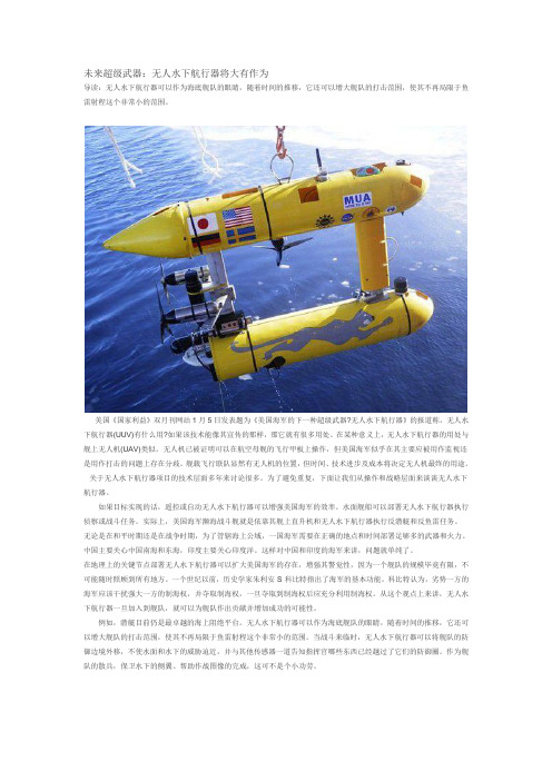
未来超级武器:无人水下航行器将大有作为导读:无人水下航行器可以作为海底舰队的眼睛,随着时间的推移,它还可以增大舰队的打击范围,使其不再局限于鱼雷射程这个非常小的范围。
美国《国家利益》双月刊网站1月5日发表题为《美国海军的下一种超级武器?无人水下航行器》的报道称,无人水下航行器(UUV)有什么用?如果该技术能像其宣传的那样,那它就有很多用处。
在某种意义上,无人水下航行器的用处与舰上无人机(UAV)类似。
无人机已被证明可以在航空母舰的飞行甲板上操作,但美国海军似乎在其主要应被用作监视还是用作打击的问题上存在分歧。
舰载飞行联队显然有无人机的位置,但时间、技术进步及成本将决定无人机最终的用途。
关于无人水下航行器项目的技术层面多年来讨论很多。
为了避免重复,下面让我们从操作和战略层面来谈谈无人水下航行器。
如果目标实现的话,遥控或自动无人水下航行器可以增强美国海军的效率。
水面舰船可以部署无人水下航行器执行侦察或战斗任务。
实际上,美国海军濒海战斗舰就是依靠其舰上直升机和无人水下航行器执行反潜艇和反鱼雷任务。
无论是在和平时期还是在战争时期,为了管辖海上公域,一国海军需要在正确的地点和时间部署足够多的武器和火力。
中国主要关心中国南海和东海,印度主要关心印度洋。
这样对中国和印度的海军来讲,问题就单纯了。
在地理上的关键节点部署无人水下航行器可以扩大美国海军的存在,增强其警觉性,因为一个舰队的规模毕竟有限,不可能随时照顾到所有地方。
一个世纪以前,历史学家朱利安·S·科比特指出了海军的基本功能。
科比特认为,劣势一方的海军应该干扰强大一方的制海权,并夺取制海权,一旦夺取到制海权后应充分利用制海权。
从这个观点上来讲,无人水下航行器一旦加入到舰队,就可以为舰队作出贡献并增加成功的可能性。
例如,潜艇目前仍是最卓越的海上阻绝平台。
无人水下航行器可以作为海底舰队的眼睛,随着时间的推移,它还可以增大舰队的打击范围,使其不再局限于鱼雷射程这个非常小的范围。
(交通运输)船舶检验计费标准湖北省交通运输厅

(交通运输)船舶检验计费标准湖北省交通运输厅船舶检验计费标准本规定由国家发展计划委员会计价费[1998]800号文批准颁布自1998年6月1日起执行目录1. 总则...........................................................................2. 设计图纸和技术文件的审查........................................................3. 建造检验........................................................................3.1 一般规定........................................................................3.2 船舶构造........................................................................3.3 轮机............................................................................3.4 电气装置........................................................................3.5 轮机自动化......................................................................3.6 货物冷藏置......................................................................3.7 锅炉...........................................................................3.8 载重线.........................................................................3.9 吨位丈量.......................................................................3.10稳性批准.......................................................................3.11散装谷物稳性批准................................................................3.12消防...........................................................................3.13救生设备.......................................................................3.14 航行设备.......................................................................3.16无线电通讯设备..................................................................3.17防止油类污染....................................................................3.18控制散装有毒液体物质污染.........................................................3.19防止船舶生活污水污染.............................................................3.20防止船舶垃圾污染................................................................. 3.21起重设备........................................................................3.22船员舱室设备....................................................................3.23乘客定额及舱室设备...............................................................4. 营运船舶检验.....................................................................4.1 一般规定.........................................................................4.2 船舶构造.........................................................................4.3 轮机.............................................................................4.4 电气装置.........................................................................4.5 轮机自动化.......................................................................4.6 货物冷藏装置.....................................................................4.7 重载线...........................................................................4.8 吨位丈量.........................................................................4.9 稳性批准.........................................................................4.10散装谷物稳性批准................................................................. 4.11消防.............................................................................4.12救生设备.........................................................................4.13航行设备..........................................................................4.15无线电通讯设备.....................................................................4.16防止油类污染.......................................................................4.17控制散装有毒液体物质污染...........................................................4.18防止船舶生活污水污染...............................................................4.19防止船舶垃圾污染...................................................................4.20起重设备...........................................................................4.21船员舱室设备.......................................................................4.22乘客定额及舱室设备.................................................................4.23坞内检验...........................................................................4.24艉轴抽出...........................................................................4.25锅炉...............................................................................4.26修理检验...........................................................................5. 拖航检验.......................................................................6. 临时检验及其他.....................................................................7. 证书费...............................................................................1总则1.1本规定适用于我国船舶检验机构对船舶检验的计费。
CSC-196电力系统时间同步装置说明书

4. 工程应用 ................................................................................................. 25
4.1. 典型时间同步系统简介.......................................................................................................... 25 4.2. CSC-196 配置方案.................................................................................................................. 26
插件布置方法 ............................................................................................................................8 电源插件(插件代码 D) ........................................................................................................8 主信号接收插件(插件代码 J) .............................................................................................9 副信号接收插件(插件代码 JF) .........................................................................................11 主信号接收插件(插件代码 G) ..........................................................................................11 副信号接收插件(插件代码 GB)........................................................................................13 串行口报文输出插件(插件代码 T)...................................................................................13 空接点型脉冲输出插件(插件代码 P)...............................................................................14 空接点型信号输出插件(插件代码 K) ..............................................................................15 多模光纤输出插件(插件代码 F).......................................................................................16 B 码输出插件(插件代码 B)...............................................................................................17 差分型信号输出插件(插件代码 C) ..................................................................................18 TTL 型输出插件(插件代码 L) ..........................................................................................19 网络对时插件(插件代码 N) ..............................................................................................20 交流 B 码输出插件(插件代码 A)......................................................................................20 单模光纤输出插件(插件代码 H) ......................................................................................21 前面板 ......................................................................................................................................22
海船营运检验规程(2010)

海船法定营运检验技术规程2009(报批稿)2010年1月目录第1章通则 (1)1.1 目的和应用 (1)1.2 定义 (1)1.3 检验申请 (2)1.4 一般要求 (3)1.5 技术问题处理原则 (3)1.6 船舶修理 (4)1.7 等效与免除 (4)第2章检验与证书 (4)第3章船体及其设备 (4)3.1 一般规定 (4)3.2 初次检验 (5)3.3 年度检验 (6)3.4 中间检验 (8)3.5 船底外部检查(坞内检查) (9)3.6 换证检验 (12)3.7 船体强度衡准 (16)3.8 船体和设备修理要求 (17)3.9 附加检验 (18)第4章船舶载重线与稳性 (28)4.1 年度检验和换证检验 (28)4.2 初次检验 (29)第5章锅炉检验 (31)5.1 一般要求 (31)5.2 内部检验 (31)5.3 锅炉的附件检验 (37)5.4 锅炉的液压试验 (37)5.5 锅炉工作状态(蒸汽)下的检验 (38)5.6 热油加热器的检验 (39)5.7 锅炉的附加检验 (39)5.8 展期检验 (39)第6章机械装置和轴系检验 (40)6.1 一般要求 (40)6.2 初次检验 (40)6.3 年度检验 (41)6.4 中间检验 (41)6.5 换证检验 (42)6.6 附加检验 (65)6.7 系泊和航行试验 (65)第7章电气设备和自动化设备 (66)7.1 一般要求 (66)7.2 电气设备检验 (66)7.3 自动化系统检验 (75)第8章货物冷藏装置 (78)8.1 一般规定 (78)8.2 初次检验 (78)8.3 年度检验 (78)8.4 换证检验 (79)8.5 附加检验 (82)8.6 冷藏装置试验 (82)第9章船舶安全设备 (82)9.1 一般规定 (82)9.2 消防设备(包括防火结构)检验和试验 (83)9.3 救生设备 (91)9.4 航行设备 (95)9.5 信号设备 (97)9.6 无线电设备 (97)第10章防污染结构和设备 (101)10.1 防止油类污染检验 (101)10.2 防止有毒液体物质污染检验 (104)10.3 防止生活污水污染检验 (108)10.4 防止垃圾污染检验 (109)10.5 防止空气污染检验 (110)第11章起重设备检验 (114)11.1 年度检验 (114)11.2 换证检验(4年度全面检验) (115)11.3 附加检验和试验 (116)11.4 不允许存在的缺陷 (116)第1章通则1.1 目的和应用1.1.1为有效实施《国内航行海船法定检验技术规则》(以下简称“国内海船法规”),确保营运船舶符合我国政府的有关法令、条例和满足本局有关规定和标准,促进船舶保持安全航行、防止船舶造成环境污染的技术条件,特制定本规程。
DNV-OS-D101(2013-10)-中文版
大疆创新裁判系统用户手册说明书
2 © 2022 大疆创新 版权所有阅读提示符号说明 禁止 重要注意事项 操作、使用提示 词汇解释、参考信息前置参考阅读1. 《裁判系统用户手册》2. 裁判系统各模块说明书建议用户首先阅读裁判系统各模块说明书,了解裁判系统各模块的功能以及安装方式,正确安装裁判系统的各模块,再通过《裁判系统用户手册》了解整个裁判系统的功能。
修改日志本手册将在每赛季根据实际情况更新两次。
手册发布后,根据规定日期生效。
日期版本修改记录生效日期 2022.03.29 V1.21. 增加第三方成品模组的限制2. 删除飞镖“R ”标朝上的限制2022.03.28 2022.01.11 V1.11. 明确底盘功率的定义2. 修订机器人整机成品及开源机器人使用规范2022.01.11 2021.10.15V1.0 首次发布 2021.10.15© 2022 大疆创新 版权所有3目录阅读提示 (2)符号说明 (2)前置参考阅读 (2)修改日志 .................................................................................................................................................. 2 1.前言 ................................................................................................................................................ 10 2.技术规范 ........................................................................................................................................ 11 2.1 通用技术规范 .. (11)2.1.1能源 .................................................................................................................................. 11 2.1.2无线电 ............................................................................................................................. 12 2.1.3光学手段 .......................................................................................................................... 12 2.1.4视觉特征 .......................................................................................................................... 13 2.1.5机器人编号 ...................................................................................................................... 13 2.1.6外观设计 .......................................................................................................................... 14 2.1.7发射机构 .......................................................................................................................... 15 2.1.8自定义控制器 .................................................................................................................. 15 2.1.9其它 ................................................................................................................................. 16 2.2 机器人整机成品及开源机器人使用规范 . (17)2.2.1充分再设计 ...................................................................................................................... 17 2.2.2非充分再设计 .................................................................................................................. 18 2.2.3 无效再设计 . (18)2.3 机器人技术规范 (19)2.3.1英雄机器人 ...................................................................................................................... 19 2.3.2工程机器人 ...................................................................................................................... 20 2.3.3步兵机器人 ...................................................................................................................... 22 2.3.4空中机器人 ...................................................................................................................... 24 2.3.5哨兵机器人 ...................................................................................................................... 26 2.3.6飞镖系统 .......................................................................................................................... 27 2.3.7 雷达 ................................................................................................................................. 31 3.裁判系统安装规范 .......................................................................................................................... 33 3.1概述 ........................................................................................................................................ 33 3.2机器人裁判系统配置 ............................................................................................................... 34 3.3 主控模块安装规范 (35)3.3.1 安装步骤 (36)3.3.2安装要求 (37)3.4电源管理模块安装规范 (38)3.4.1安装步骤 (39)3.4.2安装要求 (41)3.5灯条模块安装规范 (43)3.5.1安装步骤 (44)3.5.2安装要求 (45)3.6装甲模块安装规范 (46)3.6.1通用 (48)3.6.2安装步骤 (51)3.6.3安装要求 (56)3.6.4ID编号设置 (58)3.7测速模块安装规范 (59)3.7.1安装步骤 (60)3.7.2安装要求 (65)3.8场地交互模块安装规范 (66)3.8.1安装步骤 (67)3.8.2安装要求 (68)3.8.3场地交互模块卡 (68)3.9相机图传模块(发送端)安装规范 (68)3.9.1安装步骤 (69)3.9.2安装要求 (70)3.10相机图传模块(接收端)安装规范 (70)3.10.1安装要求 (71)3.11定位模块安装规范 (71)3.11.1安装步骤 (72)3.11.2安装要求 (72)3.1217mm荧光弹丸充能装置安装规范 (73)3.12.1安装步骤 (74)3.12.2安装要求 (75)3.12.3自制紫外灯板指导及要求 (76)3.13超级电容管理模块安装规范 (76)3.13.1安装步骤 (76)3.13.2安装要求 (78)附录一17mm 测速模块转接块工程图 (79)4 © 2022 大疆创新版权所有© 2022 大疆创新 版权所有5 附录二 参考图纸 (80)表目录表2-1 控制方式汇总 (12)表2-2 自定义控制器制作参数说明 (15)表2-3 英雄机器人制作参数说明 (19)表2-4 工程机器人制作参数说明 (20)表2-5 步兵机器人制作参数说明 (22)表2-6 空中机器人制作参数说明 (24)表2-7 哨兵机器人制作参数说明 (26)表2-8 飞镖制作参数说明 (28)表2-9 飞镖发射架制作参数说明 (28)表2-10 雷达运算平台端制作参数说明 (31)表2-11 雷达传感器端参数说明 (31)表3-1 裁判系统组成模块 (33)表3-2 机器人裁判系统模块配置 (34)表3-3 电源管理模块接口对照 (42)6 © 2022 大疆创新版权所有© 2022 大疆创新 版权所有7图目录图 2-1 平衡步兵机器人示意图 (23)图 2-2 航行外观灯有效区域 (26)图 2-3 飞镖触发装置示意图 (29)图 2-4 飞镖触发装置遮挡示意图 (30)图 2-5 飞镖触发装置内部空腔遮挡示意图 (30)图 3-1 主控模块示意图 (36)图 3-2 主控模块安装示意图 (36)图 3-3 主控模块连线示意图 (37)图 3-4 主控模块安装位置示意图 (38)图 3-5 电源管理模块示意图 (39)图 3-6 电源管理模块安装示意图 (40)图 3-7 电源管理模块接口示意图 (41)图 3-8 电源管理模块接线示意图 (41)图 3-9 灯条模块示意图 (44)图 3-10 灯条模块安装示意图 (45)图 3-11 灯条模块底部示意图 (45)图 3-12 灯条模块接线示意图 (45)图 3-13 哨兵机器人灯条模块示意图 (46)图 3-14 指定装甲支撑架示意图 (47)图 3-15 小装甲模块示意图 (47)图 3-16 大装甲模块示意图 (48)图 3-17 机器人坐标系示意图 (48)图 3-18 机器人不同底盘形态X 轴示意图 (49)图 3-19 装甲模块受力示意图 (50)图 3-20 机器人保护示意图 (51)图 3-21 底盘预留孔位 (52)图 3-22 装甲支撑架安装示意图 (52)图 3-23 装甲模块安装示意图 (53)图 3-24 装甲模块连线示意图 (53)图 3-25 底盘预留孔位示意图 (54)图 3-26 装甲支撑架安装示意图 (54)图 3-27 装甲模块安装示意图 (55)图 3-28 底盘预留孔位示意图 (55)图3-29 哨兵支撑架安装示意图 (56)图3-30 哨兵装甲安装示意图 (56)图3-31 地面机器人装甲模块ID设置示意图 (59)图3-32 17mm测速模块示意图 (60)图3-33 42mm测速模块示意图 (60)图3-34 17mm枪管示意图 (61)图3-35 测速模块安装示意图 (62)图3-36 17mm转接块零件示意图 (62)图3-37 17mm转接块固定方式示意图 (63)图3-38 17mm短枪管安装示意图 (64)图3-39 42mm枪管示意图 (65)图3-40 测速模块安装规范示意图 (66)图3-41 场地交互模块示意图 (67)图3-42 场地交互模块连线示意图 (67)图3-43 场地交互模块安装示意图 (67)图3-44 场地交互模块卡示意图 (68)图3-45 相机图传模块(发送端)示意图 (69)图3-46 相机图传模块(发送端)安装示意图 (70)图3-47 相机图传模块(接收端)示意图 (71)图3-48 定位模块示意图 (71)图3-49 定位模块安装示意图 (72)图3-50 定位模块连线示意图 (72)图3-51 定位模块安装示意图 (73)图3-52 17mm荧光弹丸充能装置示意图 (74)图3-53 紫外灯板安装示意图 (75)图3-54 电容管理模块接线示意图 (77)8 © 2022 大疆创新版权所有© 2022 大疆创新 版权所有9附录图目录附录图 1 工程机器人装甲贴纸 - 2号 (80)附录图 2 步兵机器人装甲贴纸 - 3号 (80)附录图 3 步兵机器人装甲贴纸 - 4号 (81)附录图 4 步兵机器人装甲贴纸 - 5号 (81)附录图 5 英雄机器人装甲贴纸 - 1号 (82)附录图 6 平衡步兵机器人装甲贴纸 - 3号 (82)附录图 7 平衡步兵机器人装甲贴纸 - 4号 (83)附录图 8 平衡步兵机器人装甲贴纸 - 5号 (83)附录图 9 前哨站装甲贴纸 (84)附录图 10 基地小装甲贴纸 (84)附录图 11 哨兵机器人装甲贴纸 (85)附录图 12 基地大装甲贴纸 (85)1. 前言RoboMaster参赛队伍需自行研发和制作参赛机器人,参赛机器人需满足本文档描述的所有规范,否则无法通过赛前检录。
HP OfficeJet Pro 7740 宽幅多功能一体机系列用户指南说明书

目录
1 如何操作? ................................................................................................................................................... 1
HP OfficeJet Pro 7740 Wide Format All-inOne series
用户指南
版权信息 © 2020 HP Development Company, L.P.
HP 公司通告
本文档包含的信息如有更改,恕不另行 通知。
保留所有权利。 除非版权法允许,否则 在未经 HP 预先书面许可的情况下,严 禁转载、改编或翻译本手册的内容。
2 使用入门 ...................................................................................................................................................... 2 辅助功能 ................................................................................................................................................................ 2 HP EcoSolutions(HP 与环境) ..................................................
Nordic Plow UTV-Hitch 说明书

DANSK.....................................................................16ENGLISH.................................................................... 9 NORSK..................................................................... 17FRANCAIS................................................................. 10 SVENSKA................................................................. 18IT ALINO.................................................................... 11 POLSKI..................................................................... 19NEDERLANDS.......................................................... 12 CEST INA................................................................... 20ESPANOL.................................................................. 13 MAGYAR................................................................... 21PORT UGUES. (14)XXXXXX (22)NordicUTV Plow (With Hitch Receiver)7(X 1)(X 1)(X 1)27(X 1)27121314666655(X 12)227“T”334“B”“B”982623“B”1120192119202019191021213 (T)26147” (178mm)103 (T)7 24 24ENGLISHNordic Plow UTV-Hitch InstructionsCopyright 9/24/13Safety:Read and understand the plow instruction manual before use.Scan the QRC instructional videos on the first page or watch the videos on our website before use. ()Always instruct other users before they use the plow.Operation:Risk of InjuryNever allow children tohandle the plow.Never allow anyone to walk beside or sit on the plowwhen in use.Never operate the plow over 2 to 3 mph. Keep aslow steady speed.If you hit an obstruction, immediately stop the vehicle and reversedirection.Keep the strap secured near steering column to keep it clear of front axles.Instruction Clarification:STEP 8: Assemble these nuts and bolts loosely by hand until you achieve the desired 7inch (178mm) distance from the ground to the axle hole as shown in Step 10. Then fully tighten.STEP 9: You may need to purchase separately a hitch enlarger or reducer to fit our hitch.STEP 11: Before attaching the blade to the bracket, make surethe top pivot plate (Part#3) is on top. Do not over tighten the lock nuts (Part#21) – there should be some wiggle room to allow for easy placement of the T-Handle (Part#24) into the multi-position holes.STEPS 12: We show two optional methods to attach the strap to the blade:1. Remove one of the upperbolts (Part#15) from the top of the plow and replace it with a longer bolt (Part #25). Place strap between washer and blade as shown.2. Drill a hole in the top centerof blade and attach a clip as shown in Fig. B (not included). Attach the strap or winch hook if available.FAQ’sHow long will the plow last? The lightweight design and rounded edge technology significantly reduces friction and wear of the blade. The bottom edge will show signs of pits and scratches but will not degrade the blade. In addition, each blade is reversible for added longevity.Where is the cutting edge?The Nordic Plow works extremely well without a cutting edge. The Plows angle combined with its weight and that of the machine and operator provide significant force tight to the ground. This force allows for a clean sweep of snow, slush, mulch, dirt, etc. The plow may not pick up hard, packed down snow or ice.Can I use it on uneven surfaces or grass?Yes – our rounded edge blade can be used on paver bricks, sidewalks, grass, gravel and most uneven surfaces without causing damage to the blade or surface being plowed.Will the plow leave marks on the pavement?The Nordic Plow will not leave marks on your driveway, unlike traditional steel plows that can leave rust and scratches on the pavement.Trouble Shooting & TipsBlade is not flush to ground: In the angled position, the blade will not be flush to the ground if the top pivot and bottom pivot plates are reversed.The blade flips forward when plowing:Adjust the boots and axle so that the axle is 7” (178mm) from the ground.T-Handle Hard to Insert:The top and bottom pivot bolt must be loosened to allow for some movement in the metal plates.The blade is heavy to lift with strap during operation:After you have pushed the snow or material, reverse the machine to clear the blade of the material before lifting the blade with the strap.Belly Plate Heavy to Install: Prop the belly plate up with wood or car jacks under frame of machine – then line up bolts and attach.。
《GLONASS接口控制文件》标准

前言
本标准是引用俄罗斯的《Interface Control Document of GLONASS (Virsion 5.0) 》,并结合国内标准编 排制定的实际情况编写而成,本标准与原引用文件的内容和章节编排差异见下表。
本标准由中华人民共和国信息产业部提出。 本标准由中国电子技术标准化研究所归口。 本标准起草单位:中国电子科技集团公司第二十二研究所、北京安华北斗信息技术有限公司。 本标准主要起草人:曹冲、李振瀛、李冬航。
1 范围 ....................................................................... 1
2 规范性引用文件 ............................................................. 1
3.1.7 航位推算 dead reckoning
根据当前的位置、速度和航向,推算运载体在此后某时刻的位置的导航方式。
3.1.8 目的地航路点 destination waypoint
运载体航行中要到达的地点。它可以是整个航程诸航路点中的下一个航路点,也可以是 航程的终点。
3.1.9 导航航段 navigation leg
附录 1 收到的功率电平....................................................... 34
附录 2 在UTC跳秒修正期间对用户接收机的操作建议.............................. 35
附录 3 坐标和速度的计算以及GLONASS-M 现行数据信息变换为一般形式的算法示例... 36
APPENDIX 1
附录 1
APPENDIX 2
MODIS卫星

MODIS数据的获取方式
• 国家MODIS 共享平台设计了四个不同地理位 置数据汇集系统,包括:北京、乌鲁木齐、拉 萨和三亚。这样可以保障全国数据和我国邻接 地区的数据的获取。
MODIS数据的获取方式
2 通过计算机网络获取MODIS数据
• 美国国家航空航天局为MODIS建立了一系列网站服务器和数据网络直接下 载服务器。提供无偿网络共享的数据涵盖了全球每天的数据。在线数据保 持10天,10天以前的数据通过订购,NASA 经过一定时间调取数据,然 后传给数据要求者。其网址为 • 中科院地理资源所全球变化信息研究中心MODIS 数据网,网址:http://w , • 中国农业科学院农业资源与农业区划研究所MODIS 数据网,网址:http:/ // • 武汉大学MODIS 数据网,网址:/
MODIS数据特点
• MODIS探测器是卫星上唯一将实时观测数据通过x波段向全世界直接广播, 并可以免费接收数据并无偿使用的星载仪器。
数据特点是:
1、MODIS 数据波段范围广
包括了36 个波段,数据空间分辨率包括了250 米、500 米和1000米三个尺度。
2、数据更新频率快
TERRA 和AQUA 卫星都是太阳同步极轨卫星,TERR A 在地方时上午过境,AQUA 将在地方时下午过境。TERRA 与A QUA 上的MODIS 数据在时间更新频率上相配合,加上晚间过境 数据,对于接收MODIS 数据来说,可以得到每天最少2 次白天和 2 次黑夜更新数据。这样的数据更新频率,对实时地球观测、应急处 理(例如森林和草原火灾监测和救灾)和日内频率的地球系统的研究有 非常重要的实用价值
水下无人航行器装备技术发展与作战应用研究
水下无人航行器装备技术发展与作战应用研究世界范围内开展水下无人航行器研发的国家主要为美、俄、欧亚各国等,其中以美国在役数量最多,在能源动力、自主控制、导航精度及水声通信等关键技术均处于领先水平,已形成系列化产品或装备,广泛应用于军民各领域。
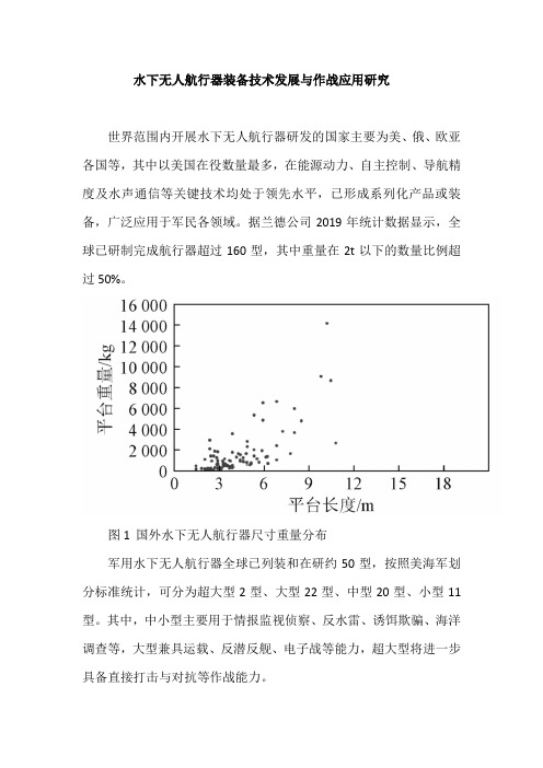
据兰德公司2019年统计数据显示,全球已研制完成航行器超过160型,其中重量在2t以下的数量比例超过50%。
图1国外水下无人航行器尺寸重量分布军用水下无人航行器全球已列装和在研约50型,按照美海军划分标准统计,可分为超大型2型、大型22型、中型20型、小型11型。
其中,中小型主要用于情报监视侦察、反水雷、诱饵欺骗、海洋调查等,大型兼具运载、反潜反舰、电子战等能力,超大型将进一步具备直接打击与对抗等作战能力。
一、国外发展现状现阶段,美国军用水下无人航行器以小型、中型、大型和超大型为发展序列,其中大型、超大型无人航行器尚处于研制验证阶段,未来将重点拓展作战能力、探索作战形式;中小型无人航行器已完成MK18系列中小型反水雷航行器、“刀鱼”中型反水雷航行器、LBS-G中型战场感知水下滑翔机等装备的列装,具备反水雷、情报监视侦察、海洋环境探测等实际作战能力,未来将进一步提升作战效能。
图2 “虎鲸”超大型无人水下潜航器畅想图超大型航行器方面以“虎鲸”超大型无人航行器为发展重点,2019年美海军正式启动5艘“虎鲸”研制建造计划,以美国波音公司“回声-航行者”型超大型无人航行器为基础进行研制,该型航行器2017年开始初次海试,长16m,重50t,潜深3300m,采用混合式可充电电力系统,续航力6个月,并装配长达10.2m的模块化有效载重舱,主要用于执行情报监视侦察、反水雷、时敏打击任务,全部5具将至2022年完成交付。
图3 “虎鲸”超大型无人航行器平台概念图图4 国外水下无人航行器典型装备大型航行器方面以“蛇头”大型航行器为发展重点,2016年海军研究办公室完成900~1100nmile长航时试验,排水量约10t,直径约1.5m,续航30d或更长,计划能够由“弗吉尼亚”级潜艇改装的导弹发射筒发射。
- 1、下载文档前请自行甄别文档内容的完整性,平台不提供额外的编辑、内容补充、找答案等附加服务。
- 2、"仅部分预览"的文档,不可在线预览部分如存在完整性等问题,可反馈申请退款(可完整预览的文档不适用该条件!)。
- 3、如文档侵犯您的权益,请联系客服反馈,我们会尽快为您处理(人工客服工作时间:9:00-18:30)。
印度独立的水下航行器(AUV)玛雅规格
国家海洋研究所(NiO),Goa,已经开发一个小的‘独立的水下航行器(AUV)玛雅’,作为一种工具应用于科学和商业。
发展资金由N.I.O和资讯科技,新德里部提供。
AUV设想的任务包括海洋学研究,海洋生物学研究,在淡水水库水质研究/水坝和沿海水域及河口环境监测,等等。
AUV是由三部分组成。
第一部分是AUV的装有传感器的防水鼻锥。
这个锥是可更换的,具有特定特征。
第二部分是核心压力组件——密封的铝合金壳体。
核心压力单位的核心有电池,电器,AUV传感器,执行器,通讯系统及电子。
第三部分是尾锥,容纳直流无刷电机推进器等装置。
(见分解图和照片)
该AUV的工作深度是200m,对不同的潜水深度,都可以保证在这些潜水深度内自由航行。
他可以按预先编程的任务路径行驶。
万一硬件出现了故障,安全保护设备可以让AUV 能够返回水面。
该航行器的任务加载是通过一个在岸上的与一个图形用户界面有关的援助射频链路。
AUV的部件分解图
AUV水下视图
AUV技术规格表
收集的任务数据
该AUV已多次在海上、淡水水库用于测试。
下列显示的图是从AUV的任务数据收集的。
图1:在阿拉伯海的海里试验取得的温度与深度图
图2:在Idduki水库获得的溶氧量和深度间的关系实验(微摩尔)
图3:AUV水下执行任务
接受AUV技术转让公司的资格标准
1.该公司必须进行登记,并具有良好业绩记录
2.有处理多学科的工程项目的经验
3.有水下系统或同系列的经验
4.充足的机械,电气和电子测试设施
5.有机械制造基础设施,电子工程,控制工程和软件支持,或与拥有这些设施的企业配合。
6.参与产品开发
7.市场优势
2008年8月25日,水下航行器技术的转让要求会被送到国家海洋研究所商务发展团。
敬请包含该文章所提到的资格证明。
