PB 15 beta new feature testing guidelines(pb15新功能测试指南)
Carling Technologies PB-Series和PD-Series产品说明书

Ground Fault Circuit Protection• PB-Series• PD-Series (SmartGuard®)ContentsPageAC Branch & Main Ground Fault Protection 1Product Specifications & Ordering Information PB-SeriesGeneral Specifications 2Ordering Scheme4Dimensional Specifications 5Wiring Diagrams 7SMARTGUARD PD-Series General Specifications 8Ordering Scheme10Circuit & T erminal Diagrams11Transforming Customer Needs into Customer SolutionsAt Carling T echnologies, we do much more than manufacture electrical components. We engi-neer powerful solutions. Working closely with your product team, we can tailor switching and cir-cuit protection solutions that meet your application needs — cost effectively.Since our founding in 1920, there are few products we haven’t turned on, fewer industries that haven’t turned to us. With five ISO certified manufacturing locations and technical sales offices worldwide, Carling T echnologies now ranks among the world’s largest privately owned manufac-turers of hydraulic/magnetic circuit breakers, thermal circuit protectors, electrical switches and assemblies, power distribution centers and electronic control systems. In regard to circuit protec-tion, we lead the industry in delivering higher ratings in smaller packages. And what makes all our breakers especially attractive is their superior performance and reliability ––– both hallmarks of Carling T echnologies .Our Ground Fault Circuit Protection products are specifically designed for those applications that could benefit from having overload, short circuit & ground fault protection in a single package.The PB-Series and PD-Series Smartguard can be used to protect several different types of equipment. Applications include:Customer Care CenterFor application assistance, we urge you to consult with our experienced staff in our CustomerCare Center. Our T echnical and Engineering staff has extensive test, research and develop-ment capabilities, and have assisted many customers in solving unique design and application problems with standard or customized products. Please refer to our location listing on the back of this catalog, for contact information for your area.We look forward to working with you.•generators•solar photovotaic systems • marine control panels•de-icing & snowmelting equipment •resistance & impedence heating systems • telecommunications • stage /theatre lighting • office machines • medical equipment • industrial automation • industrial control • UPS Systems •weldersAC Branch & Main Ground Fault ProtectionPB-Series Overload, short circuit and ground fault protection in a single package!The PB-series utilizes the hydraulic magnetic principle which provides precise operation and performance even whenexposed to extremely hot and/or cold application environments. The new PB-Series, AC Residual Current Circuit Breaker with Overcurrent Protection (RCBO), combines the ground fault protection of a GFCI with the familiar overcurrent tripping char-acteristics of a normal circuit breaker.The PB-Series is suitable for:•AC branch ground fault protection - a single circuit solution• AC main ground fault protection for a boat’s entire AC electrical system•Portable generator ground fault protectionElectricalTable A:UL Listed configurations and performance capabilities as Circuit BreakersVOLT S HERTZ(AMP S )UL Listed UL Standard 489Circuit Breakers, Molded Case, (Guide DIVQ, File E129899)UL Standard 1077Supplementary ProtectorsUL Standard 943Class A Ground Fault Circuit Interruptors UL Standard 1053Ground Fault Sensing and Relaying EquipmentAgency CertificationsKey Benefits of the PB-Series:•Increases safety around boats and marinas•Protects against electrical shock hazards in areas near water•Protects against defects in the wires & conductors•Reduces fire and shock hazards from defects in perma-nently installed appliances such as water heaters, battery chargers, lighting fixtures, etc.•Detects lower level ground faults which do not trip ordinary circuit breakers, but can lead to fires, and shock hazards for boating occupantsInnovative FeaturesThese precision mechanisms are temperature stable and are not adversely affected by temperature changes in their operat-ing environment. As such, derating considerations due to tem-perature variations are not normally required, and heat-induced nuisance tripping is avoided.• Overload, short circuit and ground fault protection in asingle package •Handle style actuators and rocker style acuguard”• Wiping Contacts - Mechanical linkage with two-stepactuation – cleans contacts, provides high, positive contact pressure & longer contact life• A trip-free mechanism, a safety feature, makes itimpossible to manually hold the contacts closed during overload or fault conditions.• A common trip linkage between all poles, another safetyfeature, ensures that an overload in one pole will trip all adjacent poles.• Front panel mounting• Integral push-to-test buttonPB-Series –General SpecificationsPB-Series –General SpecificationsStandard Must TripLeakage Current Ratings 5 & 30 milliamps.5± 1mA for UL943, other leakage ratings test to UL1053.For other ratings, consult factory.Trip Time 300 ms Max. @ 100%, 40ms Max.@ 500% of must trip leakage current.T est Button On unit face along side of actuator.Number of Poles 1 - 3 poles, where the third pole is neutral Internal Circuit Config.Series TripWeightApproximately 65 grams/pole.(Approximately 2.32 ounces/pole.)Standard ColorsHousing- Black; Actuator - See Ordering Scheme.MechanicalElectricalPhysicalEndurance10,000 ON-OFF operations @ 6 per minute; with rated Current and Voltage.Trip FreeAll PB-Series Circuit Breakers will trip on overload or ground fault,even when Handle is forcibly held in the ON position.Trip IndicationThe operating Handle moves posi-tively to the OFF position when an overload or ground fault causes the breaker to trip.Designed and tested in accordance with requirements of specifi-cation MIL-PRF- 55629 and MIL-STD-202 as follows:Shock Withstands 100 Gs, 6ms, sawtoothwhile carrying rated current per Method 213, T est Condition "I".Ultra-short curves tested @ 90% of rated current.Vibration Withstands 0.060" excursion from10-55 Hz, and 10 Gs 55-500 Hz, at rated current per Method 204C,Test Condition A. Instantaneous and ultrashort curves tested at 90% of rated current.Moisture Resistance Method 106D, i.e., ten 24-hourcycles @ + 25°C to +65°C, 80-98%RH.Salt Spray Method 101, Condition A (90-95%RH @ 5% NaCl Solution, 96 hrs).Thermal Shock Method 107D, Condition A (Fivecycles @ -55°C to +25°C to +85°C to +25°C).Operating Temperature -35° C to +65° C Corrosion T ested per UL943 FMG T est. 3weeks @ 30°C 75% RH, 100ppb H 2S, 20ppb CI 2, 200ppb NO 2EnvironmentalLeakage To GroundPB-Series –Ordering Scheme2100.1002150.1502200.2002250.2502300.3002350.3502400.4002450.4502500.5002550.5502600.6002650.6502700.7002750.7502800.8002850.8502900.9002950.950410 1.000512 1.250415 1.500517 1.750420 2.000522 2.250425 2.500527 2.750430 3.000435 3.500440 4.000445 4.5004505.000455 5.5004606.000465 6.5004707.0004757.5004808.0004858.5004909.0004959.50061010.00071010.50061111.00071111.50061212.00071212.50061313.00061414.00061515.00061616.00061717.00061818.00062020.00062222.00062424.00062525.00063030.00011Agency Approval8Actuator Color11 AGENCY APPROVAL G UL489 Listed, CSA Certified C UL10779 MOUNTING/BARRIERSMOUNTING STYLEBARRIERS Threaded Insert, 2 per pole A 6-32 X 0.195 inches yes B ISO M3 x 5mmyes7 TERMINAL 213Push-On 0.250 Tab (Q.C.)2Screw 8-32 w/upturned lugs 3Screw 8-32 (Bus Type)4Screw 10-32 w/upturned lugs 5Screw 10-32 (Bus Type)B Screw M5 w/upturned lugs C Screw M4 w/upturned lugs E Screw M4 (Bus Type)H Screw M5 (Bus Type)4Actuator5 FREQUENCY & DELA Y 2260Hz Short 2460Hz Medium 2660Hz Long3 CIRCUIT B Series Trip (Current)2 SYSTEM VOLTAGE / POLES A 120 VAC single phase, one pole B 120/240 VAC single phase, two pole C 120/240 VAC single phase with switched neutral, three pole 6Current Rating3Circuit2SystemVoltage/Poles9Mounting/Barriers7Terminal5Frequency & Delay1SeriesA B A 246202B A GNotes:1 Actuator Code:A: Handle tie pin spacer(s) and retainers provided unassembled with multi-pole units.B: Handle location as viewed from front of breaker:2 pole - left pole 3 pole - center pole 2Screw Terminals are recommended on ratings greater than 20 amps. 3UL & CSA up to 30 amps, but not recommended over 20 amps.4Available with leakage current trip level - Max trip current code E, and agency approval C.56mA per UL943, available with agency approval code G.630mA per UL1053, available with agency approval codes C & G.8 ACTUATOR COLOR & LEGENDI-O ON-OFF DualLegend Color White A B 1Black Black C D 2White Red F G 3White Green H J 4White Blue K L 5White Y ellow M N 6Black Gray P Q 7Black Orange R S 8Black6 CURRENT RATING (AMPERES)–––––PB 10Trip LevelA10 LEAKAGE CURRENT TRIP LEVEL - MAX. TRIP CURRENTA 5 mA (Class A GFCI)4,5,6E 30 mA (ELCB)1 SERIES PBNOTES:Other time delay values available, consult factory.Delay Curves 22,24,26: Breakers to hold 100% and must trip at 125% of rated current and greater within the time limit shown in this curve.All Curves: Curve data shown represents breaker response at ambient temperature of 77°F (25°C) with no preloading. Breakers are mounted in standard wall-mount position.The minimum inrush pulse tolerance handling capability is 12 times the rated current. These values are based on a 60 Hz 1/2 cycle, 8.33 ms pulse.PB-Series –Dimensional SpecificationsPB-Series –Dimensional Specifications Notes:1All dimensions are in inches [millimeters].2Tolerance ±.020 [.51] unless otherwise specified.InstantaneousShortMediumLong Time Delay CurvesPB-Series –Wiring Diagrams120/240VAC with Switched Neutral120VAC without Switched Neutral120/240VAC without Switched NeutralPD-Series –General SpecificationsSmartGuard ® PD-SeriesOverload, short circuit and equipment ground fault protection in a single package!Today’s high tech equipment demands high tech protection.Our SmartGuard Equipment Leakage Circuit Breaker (ELCB)provides that protection, in one attractive, space-saving pack-age.SmartGuard is an equipment ground fault protection device that functions as a standard high-quality Carling hydraulic/magnetic circuit breaker, offering customized overload and short circuit protection. In addition, this breaker senses and guards against faults to ground using a state of the art integrated circuit devel-oped by Carling. This new technology detects faults and when a fault occurs, the breaker trips and an LED illuminates. The LED gives a clear indication that the trip occurred as a result of leakage. This protection helps prevent serious equipment dam-age and fire.decades ago.UL Recognized UL Standard 1077Component Recognition Program as Equipment Leakage Circuit Interrupter and, Protectors,Supplementary (FTTJ2, File E177510).UL Standard 943T ested as Ground Fault Circuit Interrupters for Equipment Protection.CSA CertifiedComponent Equipment Leakage Current Interrupter with Supplementary Protector, under Class C22.2,No. 144-M91, FIle LR47848-50TUV CertifiedIEC 947-2 and appendix B: Circuit Breakers incorporating Residual Current Protection. Complies with waveform requirements of IEC 1008-1, Type A.Agency CertificationsInnovative FeaturesThese precision mechanisms are temperature stable and are not adversely affected by temperature changes in their oper-ating environment. As such, derating considerations due to temperature variations are not normally required, and heat-induced nuisance tripping is avoided.• Overload, short circuit and ground fault protection in asingle package• Handle style actuators with optional “handleguard”• Wiping Contacts - Mechanical linkage with two-stepactuation – cleans contacts, provides high, positive contact pressure & longer contact life• A trip-free mechanism, a safety feature, makes itimpossible to manually hold the contacts closed during overload or fault conditions.• A common trip linkage between all poles, another safetyfeature, ensures that an overload in one pole will trip all adjacent poles.• Front panel or DIN rail mounting options• “State of the art” integrated circuit developed by Carling • Equipment leakage sensitivity from 10 to 100 milliamps • Integral push-to-test button and LED “tripped” indicator • Immediate reset after fault has been clearedPD-Series –General SpecificationsPD-Series –Ordering Scheme410 1.000512 1.250415 1.500517 1.750420 2.000522 2.250425 2.500527 2.750430 3.000435 3.500440 4.000445 4.500450 5.000455 5.500460 6.000465 6.5004707.0004757.5004808.0004858.5004909.0004959.50061010.00071010.50061111.00071111.50061212.00071212.50061313.00061414.00061515.00061616.00061717.00071717.50061818.00061919.00062020.00062222.00062424.00062525.00063030.00063535.00064040.00065050.0005 CURRENT RATING (AMPERES)9Actuator Color8Actuator10 MOUNTING 31Threaded Insert 6-32 x 0.195 inches 2Threaded Insert ISO M3 x 6.5 mm7 TERMINAL 2Front Connected Box Lug 4 FREQUENCY & DELA Y 2050/60Hz Instantaneous 2250/60Hz Short 2450/60Hz Medium 2650/60Hz Long3 CIRCUIT B Series Trip (Current)1 SERIES PD5Current Rating3Circuit2Voltage/Poles6Equipment Leakage -Trip Current7Terminal4Frequency & Delay1SeriesR B 24650B 2A 1Notes:1Units with a switched or unswitched neutral connection are the same size as a unit withan additional breaker pole (e.g. a 2-pole unit with a switched or unswitched neutral is the same physical size as a 3-pole unit.)Switched neutral poles contain the same overcurrent protection as the other poles.2The leakage currents shown will cause the breaker to trip (must-trip current). The must-hold current is 67% of the must-trip current. 3All breakers are front panel mountable using screw size shown. Breakers may also bemounted on either 35mm x 7.5mm or 35mm x 15mm symmetrical DIN rail.4TUV certifed units must have I-O or Dual legends.11Agency Approval1CPD B 7C 10 D 15 E 30 F 50 G 1008 ACTUATOR A Handle B Handle. with handleguard 9 ACTUATOR COLOR & LEGEND 4ActuatorColor Marking: Marking Color: Color:I-O ON-OFF Dual White A B 1BlackBlack C D 2White Red E F 3White10Mounting11 AGENCY APPROVAL C UL Recognized & CSA Certified U TUV Certified6 EQUIPMENT LEAKAGE - TRIP CURRENT (milliamps)2InstantaneousShort MediumLongTime Delay Curves –––––––PD-Series –Circuit & Terminal DiagramsNotes:1All dimensions are in inches [millimeters].2Tolerance ±.020 [.51] unless otherwise specified.NOTES:Other time delay values available, consult factory.Delay Curves 21,22,24,26: Breakers to hold 100% and must trip at 125% ofrated current and greater within the time limit shown in this curve.Delay Curve 20: Breakers to hold 100% and must trip at 150% of rated currentand greater within the time limit shown in this curve.All Curves: Curve data shown represents breaker response at ambient temper-ature of 77°F (25°C) with no preloading. Breakers are mounted in standard wall-mount position.The minimum inrush pulse tolerance handling capability is 12 times the ratedcurrent. These values are based on a 60 Hz 1/2 cycle, 8.33 ms pulse.Notes:1All dimensions are in inches [millimeters].2Tolerance ±.020 [.51] unless otherwise specified.PD-Series –Circuit & Terminal DiagramsOur extensive web site provides in-depth, detailed information about our productsand capabilities. And with offices aroundthe world, we’re always ready to do business, answer questions and help our customers. Call, fax or e-mail anytime to start working with a company that’s always ON.World-WideCorporate Headquarters Carling Technologies, Inc. 60 Johnson Avenue Plainville, CT 06062860/793-9281FAX: 860/793-9231E-mail:******************** Carling TechnologiesEurope/Middle East/AfricaCarling Technologies Ltd.Devon, EnglandInt + 44 (0)1392-364422FAX: Int + 44 (0)1392-364477E-mail:************************Carling TechnologiesAsia/PacificCarling T echnologies Asia-Pacific Ltd.Kowloon, Hong KongInt + 852-2737-2277FAX: Int + 852-2736-9332E-mail:*********************.hkAdditional Carling Technologies OfficesEast Region Sales Office, CT********************Midwest Region Sales Office, IL********************West Region Sales Office, CA********************GmbH, Germany********************SARL, France,********************Asia-Pacific Ltd., Shanghai, China***************.cnAsia-Pacific Ltd., Japan*********************Pune, India*********************Kaohsiung, Taiwan**********************Warranty PolicyCarling Technologies, Inc. (Seller) warrants that goods sold hereunder shall be free of defects in material and workmanship for one year from date of shipment. In the event of such defects, the Seller’s only obligation shall be the replacement or the cost of the defective goods, themselves, excluding, without limitation, labor costs, which are or may be required in connection with the replacement or reinstallation of the goods. This warranty is the Seller’s sole obligation and excludes all other remedies or warranties, express or implied, including warranties of merchantability and fitness for a particular purpose, whether or not purposes or specifications are described herein. This Warranty expressly excludes any and all incidental, special and/or consequential damages of any nature. Seller further disclaims any responsibility for injury to person or damage to or loss of property or value caused by any prod-uct which has been subjected to misuse, negligence, or accident; or misapplied, or modified or repaired by a person or persons not authorized by the Seller or which have been improperly installed.GFCI4_。
IEC61215+标准+(中文版)[1]
![IEC61215+标准+(中文版)[1]](https://img.taocdn.com/s3/m/8a8d75d0b14e852458fb5766.png)
IEC61215 标准(中文版)美国光伏检测室( ASU-PTL)中国全权代理Solspring International Energy Group太阳普林国际能源集团(加拿大)2005年中国目的1。
决定组件的电性能和热性能。
2。
表明组件在合理的成本和时间内,能够承受长时间的气候暴露。
取样根据 IEC 60410 标准,8块用于质量测试的组件应从一批或几批产品中任意抽取。
通过的标准:1。
最大输出 (The degradation of Max. output power does not exceedthe prescribed limit after each test nor 8% after each test sequence)2。
电路 (no sample has exhibited any open-circuit during the tests)3。
目测迹象(There is no visual evidence of a major defect) 4。
绝缘性(The insulation test requirements are met after the tests)5。
湿漏电 (The wet leakage current test requirements are met at thebeginning and the end of each sequence and after the damp heat test)6。
特殊要求(Specific requirements of the individual tests are met)5kWh/m2目测,电性能,绝缘,湿漏1 12 22热循环 200电性能紫外线湿热热循环 50户外暴二极管热试验湿冻机械强度雹击热斑终端试验目测,电性能,绝缘,IEC61215 (第二版)标签每一个组件的标签都应包括以下内容且清楚可读:1. 生产厂商名字或标志。
testo 315-1 2 使用手册说明书

>7.5 V (电池寿命上 下 滚动键between the parameters,.单位同样可以被改变。
参数设定通过和 键。
All of the saved readings can be printed on the printer via the 通过 键按 键确认。
关 开testo 315-1CO • hPa µA • °C/°F 电离电流 探头接入端CO 密封帽必须关紧。
/程序段测试 (3 s)167CO167167按 键,显示所有程序段约秒钟。
位数)显示电池/充电电池电压以及显示模式显示模式 (3 长按 键秒钟,显示3位数的显示模式。
初始状态持续约 符号如图显示在显示屏上。
初始状态后,仪器自动进入测量菜单。
automatically goes to the measurement menu.密封帽必须处在闭合状态。
否则,“ 3 s5 s功能测试/使用前需进行功能测试连接软管/CO 密封帽必须盖紧./ 打开密封帽程序段测试 (3 s)152157CO 密封帽必须盖紧 /打开密封帽程序段测试 (3 s)显示电压 (3 s)符号: /测量范围162154167152 关上CO 密封帽.程序段测试 (3 s)- 功能测试测量菜单功能测试。
/当CO 若密封帽在启动时被打开,进程将被打断,在密封帽盖紧后将重新启181181保存读数HOLD 器。
接上测试夹时可能产生电流,这可能会干扰到仪器的警报系统。
in the instrument warning system. 连接测量线红色+/黑色密封帽必须盖紧./程序段测试 (3 s)打开密封帽T o avoid an electric shock it 在高于(25) eff AC 时,为了避免电击,请务必注意安全和遵守术工程师协会危险的规定。
observed when working with voltages greater than 120V (60V) DC or 50V 括号内的数值仅限于特殊领域(如:医药,农业)。
API5B标准译文(15版1)第二部分

API 5B标准译文(15版1)第二部分API量规鉴定8.1 管线管、圆螺纹套管和油管、偏梯形螺纹套管8.1.1 鉴定机构所有校对塞规及其配对的环规,在使用前均应根据第7章给出的规定,由下列公认的独立机构之一进行鉴定(见注):注:鉴定费用的价目表可以向鉴定机构索取。
a)阿根廷,布宜诺斯艾利斯:国家工业技术研究所(Instituto National de Technologia Industrial, Buenos Aires,Republic of Argentina)b)意大利,罗马:精密电子设备军工厂(Stabilimento Militare Materiali Elettronici e di Precisione, Rome, Italy)c)中国,北京:中国计量科学研究院National Institute of Metrology, Beijing, Peoples’Republic of China) (d)美国,马里兰,盖瑟斯堡:国家标准和技术研究院(National Institute of Standards and Technology, Gaithersburg, Maryland, USA)e)英国,密得塞斯,特丁顿:国家物理实物室(National Physical Laboratory, Teddington Middlesex England)f)日本,茨木:国家计量研究实验室(National Research Laboratory of Metrology, Ibaraki, Japan)5g)澳大利亚,新南威尔士,其本得尔:国家标准实验室(限于规格不大于8?的量规)。
8(National Standards Laboratory, Chippendale, New South Wales, Australia)注:任何公认独立的国家计量实验室,若证实具有API政策和规定要求的能力,就可申请成为API量规鉴定机构。
15A 精度调节电源PR15说明书

TAA-Compliant 15-Amp DC Power Supply,13.8VDC, Precision Regulated AC-to-DC ConversionMODEL NUMBER:PR15Provide precise DC power from an AC source with this compact and lightweight power supply. The PR15 efficiently converts 120 volts AC into 13.8 volts DC. It has a high power density that makes it ideal for a wide variety of applications, like 50 watt transmitters, VHF/UHF ham radios, low power linear amplifiers, test bench equipment, point-of-sale displays, and aquariums.DescriptionPrecision regulated DC power supplies are ideal for commercial/land-mobile, ham and CB radios, test bench supplies, base stations, tape players and amplifiers. Designed for years of reliable service and superior performance, they efficiently convert 120 volts AC into 13.8 volts DC (+/-0.5V). The Trim Line Series of DC power supplies offers a low-profile design with a footprint that matches the most popular radios on the market, such as Motorola, Radius, GE Monogram Series and EF Johnson models. Compliant with the Federal Trade Agreements Act (TAA) for GSA Schedule purchasesFeaturesSmaller footprint maximizes operating spaceqCrowbar overvoltage protection prevents damage to connected equipment due to overvoltagesqCurrent-limiting electronic foldback enables time-controlled automatic overcurrent protection in case of overloadqSolid state, integrated circuit maintains excellent regulation of output voltageqRegulated output voltage maintains up to 95% of no load valueqHigh quality filtering creates very low ripple/low noise operationqHeavy-duty power transformer provides complete isolation from noise on incoming AC powerqLarge heat sinks and vented cabinets supply cool operation for continuous use and long life of the unit qIlluminated on/off switchqConnectors: Hardwire terminals / Red positive (+), Black negative (-)qWorking Temperature Range: 0° C to 40° C (32° F to 104° F), 0 to 95% humidity, non-condensingq HighlightsSmaller footprint maximizesoperating spaceqCrowbar overvoltage protectionprevents damage to connectedequipment due to overvoltages qAutomatic time-controlledovercurrent protection in case of overloadqCompliant with the FederalTrade Agreements Act (TAA) for GSA Schedule purchaseqSpecificationsStorage Temperature Range: -15° C to 50° C (5° F to 122° F)q LED Indicators: Red LED indicates that DC output is being providedq© 2023 Eaton. All Rights Reserved.Eaton is a registered trademark. All other trademarksare the property of their respective owners.。
FP75 - CP75 - FP15 - CP15 USER GUIDE
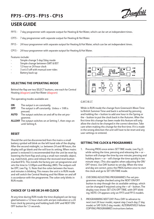
1FP75 - CP75 - FP15 - CP15USER GUIDEFP75 - 7 day programmer with separate output for Heating & Hot Water, which can be set at independent times. CP75 - 7 day programmer with separate output for Heating & Hot Water.FP15 - 24 hour programmer with separate output for Heating & Hot Water, which can be set independent times. CP15 -24 hour programmer with separate output for Heating & Hot Water.Features include:- Simple change 5 day/2day mode - Simple change between GMT & BST - 12 hour or 24 hour clock - 3 on’s/3 off with manual over-rides - Battery back-upSELECTING THE OPERATING MODEBehind the flap are two SELECT buttons, one each for Central Heating (diagram ) and Hot Water (diagram )The operating modes available are:ON The output is on constantly.OFFT he output is off constantly. Unless + 1HR is pressed.AUTO T he output switches on and off to the set pro-gramme.ALLDAY T he output switches on at Setting 1, then stays onuntil Setting 6.RESETShould the unit be disconnected from the mains a small battery symbol will blink on the left hand side of the display. After the second midnight, i.e. between 24 and 48 hours, the display will go blank and the will lose its setting. When mains power is restored it is recommended that the unit be reset by lowering the front flap and using a small non-metallic object, e.g. matchstick, press and release the recessed reset button (marked R/S). This installs the factory pre-set programme and sets the time to 12.00pm and Monday (MO). The outputs will be OFF, (see Fig. 1). Note that the colon between the hours and minutes is blinking. This means the unit is in RUN mode and will switch the Central Heating and Hot Water on and off is accordance with the programme. The colon only blinks in RUN mode.CHOICE OF 12-HR OR 24-HR CLOCKAt any time during RUN mode the time displayed can be tog-gled between a 12 hour clock with am/pm indication or a 24 hour clock by pressing and holding both DAY and NEXT ON/OFF button for 1.5 seconds.G.M.T./B.S.T.While in RUN mode the change from Greenwich Mean Time to British Summer Time and back is achieved by pressing and holding the + button to add one hour in the Spring or the – button to put the clock back in the Autumn. After the first time this change has been made this feature will only allow the clock to be changed in the correct direction. Take care when making this change for the first time. If it is made in the wrong direction the unit will have to be reset and any user-settings re-entered.SETTING THE CLOCK & PR O GRAMMES1. P ressing PROG once enters SET TIME mode, (see Fig 2)while setting the time, pressing and releasing the + or – button will change the time by one minute; pressing and holding down + or – will change the time quickly in ten minute steps. (This also applies when adjusting the ON/OFF times). Use DAY button to set day. When the time and day are correct, press the PROG button once to start the clock and go to SET ON TIME mode. 2.CHECKING/ADJUSTING PROGRAMMES : Pre-set pro-grammes maybe checked using the NEXT ON/OFFbutton to step through the six available settings, which can be changed if required using the + of – button. The display now shows SET (CH) OFF TIME, with OFF blink-ing. NOTE: CH appears only on FP75 and FP15 models. 3.PROGRAMMING NEXT DAY: Press DAY to advance to next (not 24 hour mode), repeat step 2 each day (7 day mode) or SAT-SUN (5 day mode). ALTERNATIVELY followCOPYING PROGRAMMES instructions below.24.COPYING PROGRAMMES : When a day’s settings are as required they may all be copied to the following day with just two button presses. Press DAY to change the day, then press COPY. When used with any model that has been converted to 5 day/2 day operation the pro-gramme set for Monday to Friday (MOTUWETHFR on the display) can be copied to the weekend (SASU).5.CHECKING/ADJUSTING HOT WATER PROGRAMMES (FP75 & FP15 ONLY): Press PROG to display SET, HW, ON, TIME, use NEXT ON/OF button to step through the six avail-able setting, which can be changed if required using the + or – buttons.6.RUN MODE : Having completed the programming for each day, press PROG to go to the run modeRUN MODEOPERATION : In RUN mode the unit will automatically switch the Central Heating and Hot Water on and off at the times set. However, useful over-rides are provided which enable the user to make temporary changes to the ON/OFF times with-out having to re-programme the unit. The facilities offered by the over-rides are detailed on the back cover.REVIEWING PROGRAMMES FROM THE RUN MODE : Press PROG twice, follow step 2,3,5 & 6 above (Note: step 5 applies only to FP75 and FP15).MANUAL OVER-RIDESWhile in OFF, AUTO or ALLDAY modes the plus one hour (+1HR) button can be used to switch from off to on for just one hour, or to extend and existing on period by one hour. The extra hour is cancelled by pressing the button again, pressing the MAN button, or when an on event is reached. While in AURO of ALLDAY modes pressing the manual (MAN) button will switch an output which is on to off, and viceversa. This over-ride will last only until the next programmed switching event is reached, when the automatic programme will resume control, or until the button is presses again. When the above over-ride are selected a bar appears in the display against the appropriate legend.ERROR FREE PRORAMMINGON/OFF times cannot be set out of sequence. The limits of adjustment are: Setting 1 (first ON) 12.00am to 11.59pm (nor-mally in the morning).Settings 2 to 6 (first OFF to last OFF) anywhere between the previous setting and 23 hours 59, minutes after Setting 1. The – button stops responding when the pervious Setting is reached, but the + button continues to its limit, also chang-ing any later Setting that would have been overlapped.While becoming familiar with Setting Sequence the ON/OFF times may become grouped together. If this should happen use NEXT ON/OFF to select Setting 1, then check/alter each Setting in turn, using + or – until the desired programme isentered .When programming 7 day models, FP75 & CP75, the day be-ing set appears in the display (see typical displays). With 24 hour models, FP15 & CP15, the day only appears in SET TIME mode. When models are being programmed in 5 day/2day mode then the days will show as MOTUWETHFR of SASU. Should the unit be disconnected from the mains a small bat-tery symbol will blink on the left hand side of the display.FACTORY PRE-SET PROGRAMMEThe following ON/OFF times are programmed at the fac-tory and are re-instated by pressing the recessed R/S buttonbehind the flap.NOTES ON TYPICAL DISPLAYS (see page 3)Fig 1. Immediately following a manual RESET (RUN mode with colon blinking)Fig 2. SET TIME and DAY mode (colon steady, day, hours and minutes blink)Fig 3. SET FIRST ON TIME (‘CH’ on models FP75 & FP15) (setting number and day shown, ‘ON’ blinks) Fig 4. SET FIRST OFF TIME (‘CH’ on models FP75 & FP15) (setting number and day shown, ‘OFF’ blinks) Fig 5. SET LAST OFF IMR AFTER MIDNIGHT (day when output will switch off blinks)Fig 6. SET ‘HW’ FIRST ON TIME (models FP75 & FP15 only) (setting number and day shown, ‘ON’ blinks) Fig 7.T ypical"CH" ALLDAY, "HW" AUTO programme with"HW" +1 HOUR selected.3Sequence of button presses whilst adjusting time, day and programme setting Read the section ‘Error free programming’ first.Press and release + or – to change the time by one minute.Press and hold down + or – to change the time quickly.Part No: FP75, CP75, FP15, CP15 - 19934。
minitab15

Minitab 15IntroductionMinitab 15 is a statistical software package that provides a wide range of tools and methods for data analysis and visualization. It is widely used by professionals in various fields such as engineering, manufacturing, quality control, and research. In this document, we will explore the key features and functionalities of Minitab 15.FeaturesData Import and ManipulationMinitab 15 offers various options for importing data from different sources such as Excel, CSV, and database files. Once the data is imported, Minitab provides a user-friendly interface to manipulate and clean the data. Users can perform operations such as sorting, filtering, and transforming data using simple commands and functions.Descriptive StatisticsMinitab 15 includes a comprehensive set of descriptive statistics tools. Users can calculate measures such as mean, median, standard deviation, and percentiles for single variables or multiple variables at once. Minitab also provides graphical tools to visualize the distribution of data, such as histograms, boxplots, and scatterplots.Hypothesis TestingOne of the key strengths of Minitab 15 is its ability to perform hypothesis testing. Users can conduct tests such as t-tests, chi-square tests, and analysis of variance (ANOVA) to compare means, proportions, and variances. Minitab also provides options for testing assumptions and evaluating the significance of results.Regression AnalysisRegression analysis is an important tool in statistical modeling, and Minitab 15 offers a wide range of regression techniques. Users canperform simple linear regression, multiple regression, logistic regression, and many other types of regression analyses. Minitab provides diagnostic tools to assess the goodness of fit and identify influential observations.Experimental DesignMinitab 15 supports experimental design by providing tools to plan, analyze, and optimize experiments. Users can create factorial designs, response surface designs, and other types of designs to study the effects of multiple variables on a response variable. Minitab helps users analyze the experimental data and generate statistical models to make predictions and optimize process parameters.Quality ControlQuality control is an essential aspect of many industries, and Minitab 15 offers several tools for quality control analysis. Users can create control charts, capability analysis, and statistical process control (SPC)charts to monitor and improve process performance. Minitab also includes Six Sigma tools such as process capability analysis and design of experiments (DOE) for quality improvement projects.ConclusionMinitab 15 is a powerful statistical software package that provides a wide range of tools for data analysis, hypothesis testing, regression analysis, experimental design, and quality control. Its user-friendly interface and comprehensive features make it a valuable tool for professionals in various fields. Whether you are an engineer, quality control manager, researcher, or analyst, Minitab 15 can help you make sense of your data and gain insights for making informed decisions.。
BIQ-15必要的检查确认

油漆报交可以在油漆返修前100%检查吗?
你对检验员的技能校准有什么好的建议?
你知道有哪些项目是AUDIT检查?
本条款XXX编制,有疑问请联系:XXX
BIQ15 过程控制验证-必要的-必要的检查确认 5. 问题举例
检验员技能校准跟踪
BIQ15 过程控制验证-必要的检查确认 6.问题反馈
请认真思考您的答案,并试着解决问题。 Question 问题 所有检查必须是100%进行吗? Comments 评论
2. 支持该条款的文件:
车间工序控制程序
3. 支持该条款的活动:
SIP布置,检验员的技能校准,分层审核
4. 如何做能满足条款要求:
a.检查工位上所有的文件、工具、检具配置到位 b.有交流/升级流程对问题进行升级 c.检查项目以标准化工作的方式进行描述,质量标准可用于问题判定 d.检验员完成了培训,有用于技能监控的培训计划 e.检验工位实施了分层审核流程.
BIQ15 过程控制验证-必要的检查确认 1.主题描述
核心要求:检测-在每个车间的末端至少设一个检验工位(车身,油漆,内饰,底盘,终检)并进行100% 检查。在其它区域(例如:检具,CMM,评审等)AUDIT检查是可以接受的(至少每批一台)。检查人员 的实际配置符合组织机构的设置,根据质量计划配备足够的资源(如:空间、时间、人员、设备)以保 证完成所需的质量。工具和仪器是容易得到的,并且在给定的时间内组员能完成检查。
华为产品测试策略及验证计划模板

XXX测试策略及验证计划(仅供内部使用)编制:审核:会签:批准:修订记录文件的版本号由“V ×.×”组成,其中:a)小数点前面的×为主版本号,取值范围为“0~9”。
文件进行重大修订时主版本号递增1;b)小数点后面的×为次版本号,取值为“0~9,a~z”。
文件每修改一次时次版本号递增1;主版本号发生改变时,次版本号重新置0;c)未批准发布的文件版本号为V0.×版,批准发布时为V1.0版。
当主版本号发生改变时,前面只有次版本号不同的修订记录可以删除。
目录1简介 (7)1.1 目的 (7)1.2 范围 (7)1.3 术语和缩写词 (7)1.4 关键技术 (7)2集成测试策略 (8)2.1 build 1集成测试策略 (8)2.1.1 测试环境 (8)2.1.2 测试重点分析 (9)2.2 build 2集成测试策略 (9)3Build SDV测试策略 (9)3.1 SDV测试方案描述 (9)3.2 Build 1测试策略 (10)3.2.1 测试环境 (10)3.2.2 测试重点分析 (12)3.3 Build 2测试策略 (13)4SIT系统测试策略 (13)4.1 测试环境 (13)4.2 测试重点分析 (14)5SVT测试策略 (15)6Beta测试策略 (16)6.1 Beta测试需求分析 (16)6.2 Beta测试计划 (16)7认证和标杆测试策略 (16)7.1 认证和标杆测试需求分析 (16)7.2 认证和标杆测试计划 (17)8测试环境筹备计划 (17)8.1 测试环境需求分析 (17)8.2 工具/仪器的可获得性风险评估 (18)8.3 自主开发工具详细分析 (18)8.3.1 工具名称 (18)8.3.2 工具需求分析 (19)8.3.3 资源需求分析 (19)9测试计划 (19)9.1 人力资源计划 (19)9.2 测试工具 (20)9.3 测试进度 (20)10交付工件清单 (21)11附件 (21)注:通过插入目录方式自动生成,推荐保留二级目录。
SPD15-FRSky FuriousFPV 全遥测 S.PORT 1.5KM 分集接收器用户手册说

Please contact us if you need further assistance:Tech support: ******************* Sales support: ******************** Website: /SPD15-FRSkyFuriousFPV Full Telemetry S.PORT 1.5KM Diversity ReceiverUSER MANUALIntroductionBringing forth a fusion of range, capability & feature packed brilliance, Furious FPV debuts the super compact receiver of your FPV dreams.The SPD15 is ultra-durable with a design that prevents water & dust from causing damage and it is a pint size power house boasting a full 1.5KM of reception range. Add the functionality of Two Way Duplex Transmission capability, meaning full telemetry, allowing you to keep tabs on vital information throughout your flight.Pushing the boundaries is Smart Port Technology, allowing real time adjustment of PID's, VTX settings and more - right from your transmitter. From channel selecting to VTX power output, Smart Port Technology opens all new worlds of in-flight adjustability, right where it belongs.Featuring 16 channel S-Bus output that can be flashed with different firmware via Taranis as a FrSky receiver system, the SPD15 receiver system is lighter in overall weight and smaller in size than the XSR, featuring massive functionality to push your FPV experience to the absolute limits.Reside in the EU? Furious FPV has you covered with a dedicated LBT (Listen before Talk) version, offering EU users full compatibility with LBT firmware options that are currently available.Step up to full range capability without compromise. With the Furious FPV SPD15 Receiver, epic levels of feature packed insanity await your next flight, with full capability in an ultra-compact form. Features∙Smart Port enabled, realizing two-way full duplex transmission∙S-BUS output. Support 1~16ch from SBUS channel∙Full water and dust protection∙Lighter weight and physically smaller than XSR∙Full range: up 1.5km∙Support LBT version and InternationalversionSpecifications∙Dimension: 18*26*5mm (L x W x H)∙Antenna Length: 150mm∙Weight: 3.0g∙Power input: 5.0V∙Operating Current: 100mA @5VCompatibilityFrSky X-series Module & X9D & X9DP &X9E & X12S in D16 mode.The LBT version of SPD15 receiver only works with FrSky D16-LBT Version.Binding procedure1.Turn on transmitter and go to page MODEL SETUP and select MODE D16 then go to BINDand press enter to active bind mode – as below picture.2.Connect battery for SPD15 receiver while holding F/S button. Red LED and green LED onreceiver will solid. When red LED on receiver is shut down, indicating the binding process is completed3.Turn off both transmitter and receiver.4.Turn on transmitter then plug battery for SPD15. Green LED on SPD15 is solid, this meanSPD15 is receiving signal from your transmitter. If Red LED blinks – RX lost signal. Failsafe1.Turn on SPD15 and transmitter2.Move the controls to desired failsafe position for all channels3.Fast press (<1s). Green LED will flash twice, indicating the failsafe position has been set inthe receiver.To disable Failsafe function:Turn off TX and Turn on RX then fast press (<1s). Green LED will flash twice, indicating thefailsafe function disable.Thanks for using our product。
RT9016-15PB中文资料
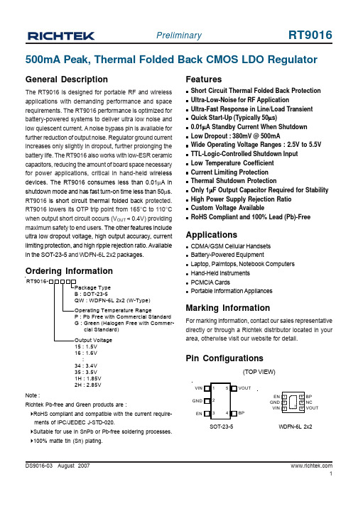
DS9016-03 August 2007500mA Peak, Thermal Folded Back CMOS LDO RegulatorMarking InformationFor marking information, contact our sales representative directly or through a Richtek distributor located in your area, otherwise visit our website for detail.Ordering InformationGeneral DescriptionThe RT9016 is designed for portable RF and wireless applications with demanding performance and space requirements. The RT9016 performance is optimized for battery-powered systems to deliver ultra low noise and low quiescent current. A noise bypass pin is available for further reduction of output noise. Regulator ground current increases only slightly in dropout, further prolonging the battery life. The RT9016 also works with low-ESR ceramic capacitors, reducing the amount of board space necessary for power applications, critical in hand-he ld wireless devices. The RT9016 consumes less than 0.01μA in shutdown mode and has fast turn-on time less than 50μs.RT9016 is short circuit thermal folded back protected.RT9016 lowers its OTP trip point from 165°C to 110°C when output short circuit occurs (V OUT < 0.4V) providing maximum safety to end users. The other features include ultra low dropout voltage, high output accuracy, current limiting protection, and high ripple rejection ratio. Available in the SOT-23-5 and WDFN-6L 2x2 p ackages.Featuresz Short Circuit Thermal Folded Back Protection z Ultra-Low-Noise for RF Applicationz Ultra-Fast Response in Line/Load Transient z Quick Start-Up (Typically 50μs)z 0.01μA Standby Current When Shutdown z Low Dropout : 380mV @ 500mAz Wide Operating Voltage Ranges : 2.5V to 5.5V z TTL-Logic-Controlled Shutdown Input z Low Temperature Coefficient z Current Limiting Protection z Thermal Shutdown Protectionz Only 1μF Output Capacitor Required for Stability z High Power Supply Rejection Ratio z Custom Voltage AvailablezRoHS Compliant and 100% Lead (Pb)-FreeApplicationsz CDMA/GSM Cellular Handsets z Battery-Powered Equipmentz Laptop, Palmtops, Notebook Computers z Hand-Held Instruments z PCMCIA CardszPortable Information AppliancesNote :Richtek Pb-free and Green products are :`RoHS compliant and compatible with the current require- ments of IPC/JEDEC J-STD-020.`Suitable for use in SnPb or Pb-free soldering processes.`100% matte tin (Sn) plating.Pin Configurations(TOP VIEW)SOT-23-5WDFN-6L 2x215 : 1.5V 16 : 1.6V :34 : 3.4V 35 : 3.5V 1H : 1.85V 2H : 2.85VEN GNDVINVIN GND BP VOUTENFunction Block DiagramFunctional Pin DescriptionTypical Application CircuitV V OUTBPENAbsolute Maximum Ratings (Note 1)z Supply Input Voltage------------------------------------------------------------------------------------------------------6Vz Power Dissipation, P D @ T A= 25°CSOT-23-5--------------------------------------------------------------------------------------------------------------------400mWWDFN-6L 2x2--------------------------------------------------------------------------------------------------------------606mWz Package Thermal Resistance (Note 4)SOT-23-5, θJA---------------------------------------------------------------------------------------------------------------250°C/W WDFN-6L 2x2, θJA---------------------------------------------------------------------------------------------------------165°C/Wz Lead Temperature (Soldering, 10 sec.)-------------------------------------------------------------------------------260°Cz Junction Temperature----------------------------------------------------------------------------------------------------150°Cz Storage T emperature Range--------------------------------------------------------------------------------------------−65°C to 150°C z ESD Susceptibility (Note 2)HBM (Human Body Mode)----------------------------------------------------------------------------------------------2kVMM (Machine Mode)------------------------------------------------------------------------------------------------------200V Recommended Operating Conditions (Note 3)z Supply Input Voltage------------------------------------------------------------------------------------------------------2.5V to 5.5Vz Junction T emperature Range--------------------------------------------------------------------------------------------−40°C to 125°C z Ambient T emperature Range--------------------------------------------------------------------------------------------−40°C to 85°C Electrical Characteristics(V IN = V OUT + 1V, C IN = C OUT = 1μF, C BP = 22nF, T A= 25°C, unless otherwise specified)To be continued DS9016-03 August Note 1. Stresses listed as the above "Absolute Maximum Ratings"may cause permanent damage to the device. These are for stress ratings. Functional operation of the device at these or any other conditions beyond those indicated in the operational sections of the specifications is not implied. Exposure to absolute maximum rating conditions for extended periods may remain possibility to affect device reliability.Note 2. Devices are ESD sensitive. Handling precaution recommended.Note 3. The device is not guaranteed to function outside its operating conditions.Note 4.θJA is measured in the natural convection at T A = 25°C on a low effective thermal conductivity test board (Single Layer, 1S) of JEDEC 51-3 thermal measurement standard.Note 5. The dropout voltage is defined as V IN -V OUT, which is measured when V OUT is V OUT(NORMAL)− 100mV.DS9016-03 August 2007Typical Operating CharacteristicsEN Pin Shoutdown Threshold vs. Temperature0.50.7511.251.51.75-50-25255075100125Temperature E N P i n S h o u t d o w n T h r e s h o l d (V )(°C)PSRR-80-60-40-20200.010.11101001000Frequency (kHz)P S R R (d B )10 100 1K 10K 100K 1M (Hz)Quiescent Current vs. Temperature6065707580859095-50-25255075100125Temperature Q u i e s c e n t C u r r e n t (u A )(°C)Output Voltage vs. Temperature1.21.31.41.51.61.71.8-50-25255075100125Temperature O u t p u t V o l t a g e (V )(°C)Dropout Voltage vs. Load Current01002003004005006000100200300400500Load Current (mA)D r o p o u t V o l t a g e(m V )Time (500μs/Div)V IN = 5VC IN = C OUT = 1uFEN Pin Shutdown ResponseE N P i n V o l t a g e (V )O u t p u t V o l t a g e (V )RT9016-28PB No Load10 5 02 1 0Time (50μs/Div)V IN = 4V to 5V C OUT = 1uF Line Transient ResponseO u t p u t V o l t a g e D e v i a t i o n (m V )I n p u t V o l t a g e D e v i a t i o n (V )RT9016-25PB I LOAD = 1mA65410 0-10Time (100μs/Div)O u t p u t V o l t a g e D e v i a t i o n (m V )10 0 -10Time (500μs/Div)RT9016-35PB V IN = 5.0VLoad Transient ResponseO u t p u t V o l t a g eD e v i a t i o n (m V )L o a d C u r r e n t (m A )C IN = C OUT = 1uFI LOAD = 10mA to 300mA400 200 050 0 -50Time (500μs/Div)Load Transient ResponseO u t p u t V o l t a g e D e v i a t i o n (m V )L o a d C u r r e n t (m A )400200 0 50 0 -50RT9016-35PB V IN = 5.0VC IN = C OUT = 1uFI LOAD = 10mA to 400mATime (10ms/Div)V IN = 4.5VC IN = C OUT = 1uF, X7RNoiseN o i s e (μV )200100 0 -100-200RT9016-15PB I LOAD = 50mAf = 10Hz to 100kHzTime (10ms/Div)V IN = 4.5VC IN = C OUT = 1uF, X7R NoiseN o i s e (μV )200100 0 -100-200RT9016-30PB I LOAD = 50mAf = 10Hz to 100kHzDS9016-03 August 2007Time (10μs/Div)V IN = 5VC IN = C OUT = 1uFStart UpE N P i n V o l t a g e (V )O u t p u t V o l t a g e (V )10 5 02 1 0RT9016-28PB No LoadApplications InformationLike any low-dropout regulator, the external capacitors used with the RT9016 must be carefully selected for regulator stability and performance. Using a capacitor whose value is > 1μF on the RT9016 input and the amount of capacitance can be increased without limit. The input capacitor must be located a distance of not more than 0.5 inch from the input pin of the IC and returned to a clean analog ground. Any good quality ceramic or tantalum can be used for this capacitor. The capacitor with larger value and lower ESR (equivalent series resistance) provides better PSRR and line-transient response. The output capacitor must meet both requirements for minimum amount of capacitance and ESR in all LDOs application. The RT9016 is designed specifically to work with low ESR ceramic output capacitor in space-saving and performance consideration. Using a ceramic capacitor whose value is at least 1μF with ESR is > 25m Ω on the RT9016 output ensures stability. The RT9016 still works well with output capacitor of other types due to the wide stable ESR range. Figure 1 shows the curves of allowable ESR range as a function of load current for various output capacitor values. Output capacitor of larger capacitance can reduce noise and improve load transient response, stability, and PSRR. The output capacitor should be located not more than 0.5 inch from the V OUT pin of the RT9016 and returned to a clean analog ground.Figure 1Bypass Capacitor and Low NoiseConnecting a 22nF between the BP pin and GND pin significantly reduces noise on the regulator output, it is critical that the capacitor connection between the BP pin and GND pin be direct and PCB traces should be as short as possible. There is a relationship between the bypass capacitor value and the LDO regulator turn on time. DC leakage on this pin can affect the LDO regulator output noise and voltage regulation performance.Enable FunctionThe RT9016 features an LDO regulator enable/disable function. To assure the LDO regulator will switch on, the EN turn on control level must be greater than 1.2 volts.The LDO regulator will go into the shutdown mode when the voltage on the EN pin falls below 0.4 volts. For to protecting the system, the RT9016 have a quick-discharge function. If the enable function is not needed in a specific application, it may be tied to V IN to keep the LDO regulator in a continuously on state.Thermal ConsiderationsThermal protection limits power dissipation in RT9016.When the operation junction temperature exceeds 165°C,the OTP circuit starts the thermal shutdown function turn the pass element off. The pass element turn on again after the junction temperature cools by 30°C.RT9016 lowers its OTP trip level from 165°C to 110°C when output short circuit occurs (V OUT < 0.4V) as shown in Figure 2. This limits IC case temperature under 100°C and provides maximum safety to end users when output short circuit occurs.For continue operation, do not exceed absolute maximum operation junction temperature 125°C. The power dissipation definition in device is :P D = (V IN −V OUT ) x I OUT + V IN x I QThe maximum power dissipation depends on the thermalresistance of IC package, PCB layout, the rate of surroundings airflow and temperature difference between junction to ambient. The maximum power dissipation can be calculated by following formula :Region of Stable C OUT ESR vs. Load Current0.000.010.101.0010.00100.000100200300400500Load Current (mA)C O U T E S R (Ω)100101R e g i o n o f S t a b l e C O U T E S R (Ω)DS9016-03 August 2007P D(MAX) = ( T J(MAX) − T A ) /θJAWhere T J(MAX) is the maximum operation junction temperature 125°C, T A is the ambient temperature and the θJA is the junction to ambient thermal resistance.For recommended operating conditions specification of RT9016, where T J(MAX) is the maximum junction temperature of the die (125°C) and T A is the maximum ambient temperature. The junction to ambient thermal resistance (θJA is layout dependent) for SOT-23-5 package is 250°C/W and WDFN-6L 2x2 package is 165°C/W on standard JEDEC 51-3 thermal test board. The maximum power dissipation at T A = 25°C can be calculated by following formula :P D(MAX) = (125°C −25°C) / 250 = 400mW (SOT-23-5)P D(MAX) = (125°C −25°C) / 165 = 606mW V(DFN-6L 2x2)The maximum power dissipation depends on operating ambient temperature for fixed T J(MAX) and thermal resistance θJA . For RT9016 packages, the Figure 3 of derating curves allows the designer to see the effect of rising ambient temperature on the maximum power allowed.Figure 3. Derating Curve for PackagesFigure 2. Short Circuit Thermal Folded Back Pro tectionwhen Output Short Circuit OccursV Short to GNDV OUTI OUTTSD0100200300400500600700255075100125150Ambient Temperature (°C)P o w e r D i s s i p a t i o n (m W )(°C)A1HLSOT-23-5 Surface Mount PackageOutline Dimension11DS9016-03 August 2007Richtek Technology CorporationHeadquarter5F, No. 20, Taiyuen Street, Chupei City Hsinchu, Taiwan, R.O.C.Tel: (8863)5526789 Fax: (8863)5526611Richtek Technology CorporationTaipei Office (Marketing)8F, No. 137, Lane 235, Paochiao Road, Hsintien City Taipei County, Taiwan, R.O.C.Tel: (8862)89191466 Fax: (8862)89191465Email: marketing@W-Type 6L DFN 2x2 Package。
3GPP 5G基站(BS)R16版本一致性测试英文原版(3GPP TS 38.141-1)

4.2.2
BS type 1-H.................................................................................................................................................. 26
4.3
Base station classes............................................................................................................................................27
1 Scope.......................................................................................................................................................13
All rights reserved. UMTS™ is a Trade Mark of ETSI registered for the benefit of its members 3GPP™ is a Trade Mark of ETSI registered for the benefit of its Members and of the 3GPP Organizational Partners LTE™ is a Trade Mark of ETSI registered for the benefit of its Members and of the 3GPP Organizational Partners GSM® and the GSM logo are registered and owned by the GSM Association
可靠性试验规范

可靠性试验规范可靠性试验规范-试验方法目次1 范围.............................................................. 错误!未定义书签。
2 术语和定义........................................................ 错误!未定义书签。
实验室环境(Laboratory environment) ............................... 错误!未定义书签。
3 试验项目.......................................................... 错误!未定义书签。
A 组环境可靠性试验................................................. 错误!未定义书签。
B组结构可靠性试验................................................. 错误!未定义书签。
4 记录.............................................................. 错误!未定义书签。
附录A 外观检查项目.............................................. 错误!未定义书签。
附录B 功能检查项目.............................................. 错误!未定义书签。
附录C 射频检查项目.............................................. 错误!未定义书签。
图表目录表1 外观检查项目.................................................... 错误!未定义书签。
表2 功能检查项目.................................................... 错误!未定义书签。
R-78HB15-0.5L中文资料

10
50
100
200
300
400
Output Current ( A )
Output Current ( mA )
Efficiency Vs Load ( Vin=Min )
元器件交易网
Features
● ● ● ● ● ● ● ● ●
Efficiency up to 96%,Non isolated, no need for heatsinks Pin-out compatible with LM78XX Linears Low profile( L*W*H=11.5*8.5*17.5mm) High voltage input range, up to 72V Short circuit protection, Thermal shutdown Non standard outputs available as specials between 3.3V~24V Low ripple and noise ”L” version with 90° pins See Positive to Negative Converter Application Note for use as a voltage inverter (alternative to LM79xx Linear)
Derating-Graph
(Ambient Temperature)
120 100 80 60 40 20 0
Output Power (%)
Safe Operating Area
-40
0
25
50
Operating Temperature (°C)
85 75 100 71
PRO FS 15R FOLLOWSPOT 产品说明书

PRO FS 15R FOLLOWSPOT™SKU# PFS001The new PRO FS 15R™ is a high output medium throwfollowspot featuring the Phillips™ MSD Platinum 15Rlamp, 2,000 hour average lamp life, 13,500 totallumens with 5° to 10° manual zoom, (5) dichroiccolors including CTB and white, (4) manual gel frameholders, 0-100% smooth dimming, manual iris, frost,and framing effects, variable color temperaturesettings (3,200K - 6,800K), powerCON in, (6) button (2)fader control panel, 400W max power consumption,a multi-voltage universal auto switching power supply(100-240v), and included tripod stand and road case.FEATURESPhillips™ Platinum MSD 15R 300W 13,500 Total Lumens10,7700LUX1,************(10m)(6° Full On)5° - 10° Manual Zoom and Focus(5) Dichroic Colors Including CTB plus White(4) Manual Gel Frame Holders0-100% Smooth DimmingManual Iris, Frost, and Framing EffectsVariable Color Temperature Settings (3,200K - 6,800K)Tripod Stand and Road Case IncludedSpecifications are subject to change without notice ©Elation ProfessionalElation Professional USA | 6122 S. Eastern Ave. | Los Angeles, CA. 90040323-582-3322|323-832-9142fax||************************Elation Professional B.V. | Junostraat 2 | 6468 EW Kerkrade, Netherlands+31455468566|+31455468596fax|www.elationlighting.eu|***********************ELATIONIPRO FS 15R FOLLOWSPOT™IProduct Specification SheetCTBFEATURES5° - 10° Manual Zoom13,500 Total Lumens(5) Dichroic Colors Including CTB plus White(4) Manual Gel Frame HoldersVariable Color Temperature Settings (3,200K - 6,800K) SOURCEPhillips™ MSD Platinum 15R Lamp2,000 Hour Average Lamp LifePHOTOMETRIC DATA10,770LUX1,**********’(10M)(6°FullOn) EFFECTSIris and FramingFrostSmooth Dimming (0-100%)CONTROL / CONNECTIONS(4) Push Buttons(2) Faders (Dimming + Color Temperature) powerCON InSIZE / WEIGHT - FollowspotLength: 42.0” (1068mm)Width: 14.9” (376mm)Vertical Height: 10.0” (255mm)Weight: 52.0 lbs. (24 kg)SIZE / WEIGHT - Road CaseLength: 46.0” (1170mm)Width: 26.8” (680mm)Vertical Height: 25.6” (650mm)Weight: 174.0 lbs. (79 kg) (with followspot + stand) ELECTRICAL / THERMALAC 100-240V - 50/60Hz400W Max Power Consumption14° to 113°F (-10° to 45°C)APPROVALS / RATINGS CE | IP20 INCLUDED ITEMS (1) powerCON Cable (1) Tripod Stand (1) Road Case8.3”(210mm)Min Total Height44.5” (1.1m)93.0” (2.4m)specifications I ELATION PRO FS 15R FOLLOWSPOT™ ISpecifications are subject to change without notice ©Elation ProfessionalElation Professional USA | 6122 S. Eastern Ave. | Los Angeles, CA. 90040323-582-3322|323-832-9142fax||************************Elation Professional B.V. | Junostraat 2 | 6468 EW Kerkrade, Netherlands+31455468566|+31455468596fax|www.elationlighting.eu|***********************COLORSPRODUCT SPECIFICATIONS PHOTOMETRIC DATA50mm ft m ft m ft m ft m ftDistance1032.82065.63098.440131.250164.06° Beam Diameter 1.2 3.9 2.1 6.9 3.110.2 4.514.8 5.819.0lux fc lux fc lux fc lux fc lux fcFULL ON10,7701,0013,4503211,8691741,021*******10°m ft m ft m ft m ft m ftDistance1032.82065.63098.440131.250164.010° Beam Diameter 1.9 6.2 3.310.8 4.615.1 6.320.78.327.2lux fc lux fc lux fc lux fc lux fcFULL ON4,8374491,63615285680273251029DIMENSIONAL DIAGRAMS。
- 1、下载文档前请自行甄别文档内容的完整性,平台不提供额外的编辑、内容补充、找答案等附加服务。
- 2、"仅部分预览"的文档,不可在线预览部分如存在完整性等问题,可反馈申请退款(可完整预览的文档不适用该条件!)。
- 3、如文档侵犯您的权益,请联系客服反馈,我们会尽快为您处理(人工客服工作时间:9:00-18:30)。
1 New Properties for Graph DataWindow in IDE Two new properties, Palette and Template, are introduced in the Graph DataWindow in PowerBuilder .NET.1.1 Palette property for Graph DataWindowPowerBuilder 15 introduces a new Palette property for the Graph DataWindow for all PowerBuilder .NET targets. It is a brush array. Users can define a Palette property to draw the series of the graph.Click the ellipsis (...) in Palette property. The Palette dialog opens and you can define the palette.1.2 Template property for Graph DataWindowPowerBuilder 15 introduces a new Template property for the Graph DataWindow for all PowerBuilder .NET targets. Use this property to save the Graph DataWindow template to a file or import a file to a Graph DataWindow. It is easy for users to create Graph DataWindows with a unified style, such as font, back color, etc.Click the ellipsis (...) in Template property. The Template dialog opens: click the SaveToFile… button. All property values of the Graph DataWindow are saved to an .XML file.Click LoadFromFile, and then click the Apply button to apply all the properties from the .XML file to the current Graph DataWindow.2 PB15 OData Support Test GuidelinePowerBuilder 15 introduces the OData Service datasource for the DataWindow. To use this new datasource, users can create an OData profile under ODT interface in the Database painter, and then create a DataWindow based on this OData profile.In Beta, you can test the following features:Database painter:∙Create an OData profile based on an OData Service URI.∙Connect the OData profile and check the tables, columns of the tables, and datatype for each column.∙Retrieve data from the table.∙Delete an OData profile.Extended Catalog:∙Create display formats for the string, number, and DateTime datatypes, then use them in columns of various datatypes. Check the display format when retrieving data in Database painter.∙Create edit styles for each style like CheckBox, DropDownListBox, EditMask, RadioButtons, etc. Use them in the columns of a table. Check the display result when retrieving data in the Database painter.∙Create validation rules for the string, number, and DateTime datatypes, then use them in the columns of a table. Check whether the validation rule takes effect when inputting an invalid value in eachcolumn in Database painter.∙Change properties for the columns of a table like comments and label of the header, position, heading, etc. Check whether these properties take effect when retrieving data in Database painter.DataWindow wizard:∙Create a DataWindow using OData profile for each presentation style like Grid, Freeform, Tabular, Crosstab, Group, TreeView, etc.∙Create a DataWindow using OData profile, and set some criteria using retrieval argument(s) in SQL painter when going through the DataWindow wizard.DataWindow painter:∙Switch to SQL painter to change table and columns.∙Switch to SQL painter to change retrieval criteria, use retrieval argument(s) in various datatypes like string, number, DateTime, etc.∙Use DataWindow preview to check the data, check the display format, edit style and validation rule as well if you set them in Database painter or DataWindow painter.Runtime:∙Consume an OData Service which includes various datatypes in runtime.∙Consume an OData Service which requires authentication in runtime.∙Consume an OData Service through firewall.Limitations:∙Since OData Service is not a SQL DataSource, ISQL sessions will not work in the Database painter and embedded SQL statements are not supported in PowerScript.∙Edm.Binary and Edm.DateTimeOffset are not supported.∙Extended catalog information is saved in the registry, so you need to export this information from the registry before uninstall/re-install PowerBuilder 15, otherwise this information will be lost.∙For Edm.DateTime, PowerBuilder can only show 6 digits for the second precision.∙Update operation is not supported in Database painter; it is only supported in DataWindow runtime.2.1 Examples∙Extended catalog∙RuntimeConsume an OData Service from scratch:1)Create an OData profile in Database painter using the URI below, call it odt_test:/OData/OData.svc/2)Right-click odt_test. Select Properties in the context menu to open the OData Profile Setup dialog.Select the OData Extended Catalog check box.3)Connect to odt_test in Database painter. In Extended Attributes view, create a display format forDateTime datatype and input format yyyy-mm-dd hh:mm:ss.4)In Database painter, expand odt_test > Tables > Products > Columns. Right-click ReleaseDate and selectProperties in the context menu. In Properties view, switch to Display tab and use the display format you created in step 3.5)Create a WPF application. Create a DataWindow using OData Service and choose OData profileodt_test, Select the Products table and select all columns in SQL dialog. Call this DataWindow d_test.6)Create a window w_test. Add a DataWindow control and set the data object to d_test. Add this scriptin the window’s open event:SQLCA.DBMS = "ODT"SQLCA.ServerName = "odt_test"SQLCA.DBParm ="ConnectString='URI=/OData/OData.svc/'"connect;dw_1.settransobject(SQLCA)dw_1.retrieve()3 PowerBuilder 15 Native 64-bit Testing Guidelines3.1 Design timePlatform is introduced in the Project painter. You can change the platform to 64-bit, then deploy and run the application on a 64-bit OS.3.2 RuntimeTry all PowerBuilder controls, including properties, functions, and events in a 64-bit applicationAll controls should have the same behavior as a 32-bit application except the RichText control. The RichText control has some differences between 32-bit and 64-bit.Using 64-bit Database driverOLE DB and DIR database interfaces are not supported in 64-bit platforms; all other types of drivers are supported.For WPF 64-bit application, using 64-bit application database driverUsing the 64-bit application database driver, build a WPF application as any CPU and run it on a 64-bit OS.3.3 New datatype – longptrThe longptr datatype is 4 bytes in the 32-bit platform and 8 bytes in the 64-bit platform. In the 32-bit platform, longptr is the same as long; you can continue using long wherever longptr is required in 32-bit applications. In 64-bit applications, however, using long to hold longptr variables will lead to data truncation from 8 bytes to 4 bytes, or memory corruption if you pass a long ref variable when a longptr ref is required. So, if you want to move to 64-bit, please use longptr wherever required. It does no harm to 32-bit.Since PowerBuilder does not have a datatype corresponding to the C++ pointer type, and there are no pointer operations in PowerBuilder, longptr is not a full-fledged PowerBuilder datatype. You can use it to hold/pass window handles, database handles, and other objects that are essentially memory addresses. Doing complex operations on longptr type may not work. If you want to represent/compute 8-byte long integers, use longlong.Unsupported features in native 64-bit application:∙COM+ runtime∙DataWindow Web control for ActiveX∙TabletPC∙PBNI SDK for developing 64-bit PB Extensions∙Machine-code generation∙Application server support4 MDI Docking WindowsThe MDI docking windows feature provides an alternative to the classic MDI feature. It allows opened sheets to be laid out as in the PowerBuilder .NET IDE. The following items can be tested:∙New window types — MDIDock and MDIDockHelp — and the four docking states: Tabbed document, Docked, Floating, and Tabbed Window∙Opening sheets in specific state∙Persisting MDI state∙Use new properties to create a good user experience for the final application4.1 New window types and four docking statesWe are adding two new WindowType values to the Window object: mdidock! and mdidockhelp!. Like mdi! and mdihelp!, respectively, they allow child windows (sheets) to be opened with the OpenSheet functions. But these sheets behave differently: they can dock, float and be tabbed like the windows you see in the PowerBuilder .NET IDE.Your sheets open docked by default. The sheets can be in one of four states:∙Tabbed Document: in PowerBuilder .NET IDE, script editors and window painters are tabbed documents – anything with an entry in the Window menu. See Figure 1.∙Docked: all other windows in PowerBuilder .NET IDE, such as Toolbox, Solution Explorer, etc.∙Floating∙Tabbed Windows: docked windows occupying the same space are tabbed. The tabs appear at the bottom. In the PowerBuilder .NET IDE, the Solution Explorer and Properties window are usuallydocked at the same location and appear as windows in a tabbed group. The main differences withtabbed documents are that tabbed windows have tabs at the bottom and have no correspondingentries in the Windows menu.4.2 Opening sheets in specific stateTo open a sheet at a specific docking location, in a specific tab group, or as a document, use one of the new versions of the OpenSheet function:∙OpenSheetAsDocument∙OpenSheetDocked∙OpenSheetInTabGroup∙OpenSheetWithParmAsDocument∙OpenSheetWithParmDocked∙OpenSheetWithParmInTabGroupOpenSheetInTabGroup and OpenSheetWithParmInTabGroup, as their names suggest, open a sheet in a tab group. Unlike the other OpenSheet functions, these take as one of their arguments not the parent window but a sibling sheet. These sibling sheets must either be docked or be in a tab group.4.2.1 OpenSheetAsDocument / OpenSheetWithParmAsDocumentint OpenSheetAsDocument(ref Window o,Window s,string i)int OpenSheetAsDocument(ref Window o,string n,Window s,string i)int OpenSheetAsDocument(ref Window o,Window s,string i,boolean v)int OpenSheetAsDocument(ref Window o,string n,Window s,string i,boolean v)int OpenSheetWithParmAsDocument(ref Window o,readonly string a,Window s, string i)int OpenSheetWithParmAsDocument(ref Window o,readonly double a,Window s, string i)int OpenSheetWithParmAsDocument(ref Window o,readonly PowerObject a,Window s, string i)int OpenSheetWithParmAsDocument(ref Window o,readonly string a, string n, Window s, string i)int OpenSheetWithParmAsDocument(ref Window o,readonly double a, string n, Window s, string i) int OpenSheetWithParmAsDocument(ref Window o,readonly PowerObject a,string n,Window s,string i) int OpenSheetWithParmAsDocument(ref Window o,readonly string a,Window s,string i,boolean v)int OpenSheetWithParmAsDocument(ref Window o,readonly double a,Window s, string i, boolean v) int OpenSheetWithParmAsDocument(ref Window o,readonly PowerObject a,Window s,string i,boolean v)int OpenSheetWithParmAsDocument(ref Window o,readonly string a,string n,Window s,string i,bool v)int OpenSheetWithParmAsDocument(ref Window o,readonly double a,string n,Window s,string i,bool v)int OpenSheetWithParmAsDocument(ref Window o,readonly PowerObject a,string n,Window s,string i,bool v)The arguments o, s, a and n have the same role as the legacy OpenSheet and OpenSheetWithParm functions.Tabbed Documents in the Visual Studio IDE can be in more than one tab group. We allow this, too. The extratab group can be created interactively by dragging a document tab to the extremities of its tab group. Whenthere is more than one tab group, you can use the s argument to specify in which one to open a sheet. Insteadof specifying the parent window, specify an already open sheet in the tab group where you want to open your new sheet.The i argument is a unique string identifier to identify the sheet, which is used when layout is persisted. See below for how to use this identifier when re-launching your application with your layout restored. (This argument can be an empty or null string if you do not want to restore the layout.)The v argument is an optional argument. When used, it causes a new tab group to be created and your sheet opens in the new tab group. When true, the tab group is vertically aligned. When false, it is horizontally aligned.4.2.2 OpenSheetDocked / OpenSheetWithParmDockedint OpenSheetDocked(ref Window o, Window s, WindowDockPosition e, string i)int OpenSheetDocked(ref Window o, string n, Window s, WindowDockPosition e, string i)int OpenSheetWithParmDocked(ref Window o,readonly string a,Window s,WindowDockPosition e,string i)int OpenSheetWithParmDocked(ref Window o,readonly double a,Window s,WindowDockPosition e,string i)int OpenSheetWithParmDocked(ref Window o,readonly PowerObject a,Window s, WindowDockPosition e, string i )int OpenSheetWithParmDocked(ref Window o,readonly string a,string n,Windows,WindowDockPosition e, string i )int OpenSheetWithParmDocked(ref Window o,readonly double a,string n,Window s, WindowDockPosition e, string i )int OpenSheetWithParmDocked(ref Window o,readonly PowerObject a,string n,Window s, WindowDockPosition e, string i )The new WindowDockPosition enumerated typeWindowDockLeft!WindowDockRight!WindowDockTop!WindowDockBottom!The arguments o, s, a and n have the same role as the legacy OpenSheet and OpenSheetWithParm functions.The i argument is a unique string identifier to identify the sheet, used when layout is persisted. See below for how to use this identifier when re-launching your application with your layout restored. (This argument can be an empty or null string if you do not want to restore the layout.)The e argument specifies where to dock the sheet.4.2.3 OpenSheetInTabGroup / OpenSheetWithParmInTabGroupint OpenSheetInTabGroup(ref Window o, Window s, string i)int OpenSheetInTabGroup(ref Window o, string n, Window s, string i)int OpenSheetWithParmInTabGroup(ref Window o,readonly string a,Window s, string i )int OpenSheetWithParmInTabGroup(ref Window o,readonly double a,Window s, string i )int OpenSheetWithParmInTabGroup(ref Window o,readonly PowerObject a,Window s, string i )int OpenSheetWithParmInTabGroup(ref Window o,readonly string a,string n,Window s, string i ) int OpenSheetWithParmInTabGroup(ref Window o,readonly double a,string n,Window s, string i ) int OpenSheetWithParmInTabGroup(ref Window o,readonly PowerObject a,string n,Window, stringi )The arguments o, a and n have the same role as the legacy OpenSheet and OpenSheetWithParm functions.The s argument is NOT the parent window. It must be a sibling window in either a docked state or in a non-document tab group. The sheet opens in the same tab group. The first sheet opened in a main window cannot be opened using these functions. To create a tab group, open the first sheet as a docked sheet and then usethis sheet as the s argument. The s argument determines in which tab group the newly opened sheet opens. Example: Open dock window and tabbed document window1. Create a window “w_sheet_any” which window type is main!2. Create MDIDock window w_mdidock_dockstate and set any menu in it.3. In “w_mdidock_dockstate” open event , write codes as shown in Figure 1.4. In “w_sheet_any” open event , add following codestring ls_ils_i = Message.stringparmif not isnull(ls_i) and ls_i <> "" thenthis.title = ls_iend if5. Run it. You will get result like Figure 2.Figure 1Figure 24.3 Persisting MDI stateWhen you launch the PowerBuilder .NET IDE, it restores all the open windows at exactly the same position and state as when you closed it. In PowerBuilder 15.0 there is an easy way to get the same thing.The most important thing is to be able to associate a meaningful string ID to each opened sheet. One way is to set it as an argument in new OpenSheet functions; another is to set it using the new SetSheetID function.The MDI state is stored in the registry using the new SaveDockingState function that you should call when your application is closed.4.3.1 SetSheetIDIf the user did not set the ID in the new OpenSheet functions (empty or null string as ID), he can do it using the SetSheetID function. It is also a way to change the ID.int SetSheetID(string i)The i argument is the ID.For example:window win[]opensheetdocked(win[1], this, WindowDockLeft!, "")win[1].SetSheetID(“11111” )4.3.2 SaveDockingStateThis function stores the MDI state in the registry (HKEY_CURRENT_USER\SOFTWARE\...). This is a method of the Window object.integer SaveDockingState(string r)The r argument is the registry key.If no entry for the key exists in the registry, one will be created. Existing keys are overwritten.4.3.3 CommitDocking / LoadDockingStateWhen your application launches, three new functions help you restore your sheets.LoadDockingState fills two equal-sized arrays. One is an array of type names of persisted sheets. The other is the corresponding IDs. For these persisted sheets, new functions are introduced to open them: OpenSheetFromDockingState (and OpenSheetWithParmFromDockingState). When all persisted sheets are open, the CommitDocking function does the work of arranging everything in place and making them visible.integer CommitDocking()integer LoadDockingState(string r, ref string w[], ref string i[])The r argument is the registry key.The w argument is an array of window type names of child windows persisted.The i argument is an array of IDs of child windows persisted.4.3.4 OpenSheetFromDockingState / OpenSheetWithParmFromDockingStateint OpenSheetFromDockingState (ref Window o, Window p, string i)int OpenSheetFromDockingState (ref Window o, string n, Window p, string i)int OpenSheetWithParmFromDockingState(ref Window o,readonly string a,Window p, string i )int OpenSheetWithParmFromDockingState(ref Window o,readonly double a, Window p, string i )int OpenSheetWithParmFromDockingState(ref Window o,readonly PowerObject a,Window p, string i ) int OpenSheetWithParmFromDockingState(ref Window o,readonly string a,string n,Window p,stringi)int OpenSheetWithParmFromDockingState(ref Window o,readonly double a,string n,Window p, stringi)int OpenSheetWithParmFromDockingState(ref Window o,readonly PowerObject a,string n,Window p,string i)The arguments o, p, a and n have the same role as the legacy OpenSheet and OpenSheetWithParm functions. The i argument is the ID of the persisted sheet.Example: 1. Save all sheets in registerinteger li_rtnstring is_register = "Sybase\PowerBuilder\Examples\Docking\"li_rtn = this.SaveDockingState( is_register )2. Restore all sheetsstring s1[], s2[]string is_register = "Sybase\PowerBuilder\Examples\Docking\"integer li_start, li_end, li_i, li_rtnli_rtn = LoadDockingState(is_register,s1,s2)window lw_windowli_start = lowerbound(s1)li_end = upperbound(s2)for li_i = li_start to li_endopenSheetFromDockingState(lw_window,s1[li_i], this, s2[li_i])nextCommitDocking()4.4 Use new properties to create a good user experience for the finalapplicationTo give you more control over the look and feel of your final application, there will be new properties to allow you to specify:∙The colors of active and inactive Title bars: horizontal/vertical gradients optional∙The colors of the area behind tabs: horizontal/vertical gradients optional∙The colors of the tabs: active/inactive/mouseover (deferring to theme colors is also an option)∙The shape of the tabs∙The location of the close button for the tabs∙Whether to show all the tabs (squeezed) or scroll themIf you create window with type MDIDock or MDIDockHelp, you will get new Docking property tab page in the Properties view of PowerBuilder Classic IDE. All new properties can be set in this tab page. You can also set them in your code.In the Docking tab, you can change the Property Set value to set related properties for TabbedDocument or TabbedWindow.∙TabbedDocumentTabShape / TabbedWindowTabShapeValue: 1. Windowdocktabsingslanted!2. Windowdocktabslanted!3. Windowdocktabrangular!Description: By changing this selection, you can set shape of tab like following picturesfor example: 1.2.∙TabbedWindowTabCloseButton / TabbedDocumentTabCloseButtonValue: 1. WindowDockTabCloseButtonNone!2. WindowDockTabCloseButtonOnActive!3. WindowDockTabCloseButtonShared!Description: By changing this selection, you can set close button display typefor example: 1. WindowDockTabCloseButtonOnActive2. WindowDockTabCloseButtonShared∙TabbedWindowTabIcon / TabbedDocumentTabIconDescription : display window icon or not∙TabbedWindowTabScroll / TabbedDocumentTabScrollDescription : display scroll arrow button on tab page or notfor example : following picture display scroll arrow button∙TabbedWindowTabColorsUseTheme / TabbedDocumentTabColorsUseThemeDescription : use window’s theme or user definedfor example : if this option not checked, user can set tab colors which include three states( active, inactive,mouseover) and three kinds of color( BackColor, GradientBackColor, TextColor)In the Docking tab, if the TabbedWindowTabColorsUseTheme or TabbedDocumentTabColorsUseTheme check boxes are unchecked, you can change the selection of Property Set (Tab State) to choose which tab state color you want to set: active, inactive, or mouseover.∙TabbedWindowActiveTabBackColor / TabbedDocumentActiveTabBackColor∙TabbedWindowActiveTabGradientBackColor / TabbedDocumentActiveTabGradientBackColor∙TabbedWindowActiveTabTextColor / TabbedDocumentActiveTabTextColor∙TabbedWindowInActiveTabBackColor / TabbedDocumentInActiveTabBackColor∙TabbedWindowInActiveTabGradientBackColor / TabbedDocumentInActiveTabGradientBackColor ∙TabbedWindowInActiveTabTextColor / TabbedDocumentInActiveTabTextColor∙TabbedWindowMouseoverTabBackColor / TabbedDocumentMouseoverTabBackColor∙TabbedWindowMouseoverTabGradientBackColor /TabbedDocumentMouseoverTabGradientBackColor∙TabbedWindowMouseoverTabTextColor / TabbedDocumentMouseoverTabTextColor for example :1. Inactive color :2. MouseOver Color3. Active color∙TabbedWindowTabsAreaColor / TabbedDocumentTabsAreaColor∙TabbedWindowTabsAreaGradientColor / TabbedDocumentTabsAreaGradientColor∙TabbedWindowTabsAreaGradientVert / TabbedDocumentTabsAreaGradientVertfor example : 1. Area color of TabbedDocumentIn the Docking tab, you can change the selection of Property Set (Title Bar State) to choose which title bar state color you want to set: active or inactive.∙TitleBarActiveColor / TitleBarInActiveColor∙TitleBarActiveGradientColor / TitleBarInActiveGradientColor∙TitleBarActiveGradientVert / TitleBarInActiveGradientVert∙TitleBarActiveaTextColor / TitleBarInActiveTextColorfor example: 1. Color of active title bar2. Color of inactive title barWindowDockOptionsValues:1.WindowDockOptionAll!2.WindowDockOptionTabbedDocumentOnly!3.WindowDockOptionDockedOnly!4.WindowDockOptionFloatOnly!5.WindowDockOptionTabbedDocumentAndDockedOnly!6.WindowDockOptionTabbedDocumentAndFloatOnly!7.WindowDockOptionDockedAndFloatOnly!Description: A property will be introduced on child windows to control what states to allow on that window.For example, if you set a sheet’s property WindowDockOption toWindowDockOptionTabbedDocumentAndFloatOnly!, its state can’t be docked as following picture when opening it in MDIDock or MDIDockHelp window.。