意大利MACRI液电混合数控弯管机
迈克尔顿工业有限公司 Stealth XC

Filter Size
6 x 14 (152 x 356)
3
6, 8, 10, 12
26 47 18 41 7
(125, 203, 254, 305) (660) (1194) (457) (1041) (178)
6 x 18 (152 x 457)
9 1/8 x 10 1/2 6 x 18 (232 x 267) (152 x 457)
W W2 H
1
4, 5, 6, 8
20 41 14
(102, 127, 152, 203) (508) (1041) (356)
L
36 (914)
Induced Air
B
Inlet
IW x IH
6
6 x 14
(152) (152 x 356)
Outlet Discharge DW x DH
8 1/8 x 4 1/4 (206 x 108)
q Hot Water Coil Section Model 35SWXC STEALTH XC
Standard Features:
• Coil section installed on unit discharge. • Coil (and header on multi-circuit units) is installed in
ENGINEER:
DATE
B SERIES SUPERSEDES DRAWING NO.
CONTRACTOR:
11 - 4 - 22 3500 10 - 28 - 22 35SXC-1
Nailor Industries Inc. reserves the right to change any information concerning product or pricing without notice.
阿玛尼折弯机操作方法

阿玛尼折弯机操作方法阿玛尼折弯机是一种用于将金属板材进行弯曲加工的设备,在制作金属制品时具有重要的作用。
以下是阿玛尼折弯机的操作方法。
1. 步骤一:设定参数首先,操作人员需要根据所要制作的工件的尺寸和弯角来设定阿玛尼折弯机的参数。
参数包括板材厚度、板材宽度、折弯角度以及回弹值等。
这些参数的设定对于保证加工结果的准确性非常重要。
2. 步骤二:调整上下模具将要加工的金属板材放置在阿玛尼折弯机上。
然后,操作人员需要根据板材的厚度和宽度来选择合适的上下模具,并进行安装和调整。
上下模具的选择和调整要保证金属板材能够完全嵌入模具中,并保持良好的接触。
3. 步骤三:设定折弯角度根据工件的设计要求,操作人员需要设定阿玛尼折弯机的折弯角度。
通常情况下,折弯角度可以通过设定折弯机上的数控系统来进行调整。
一般来说,数控系统会有一个数字显示屏,操作人员可以根据需要输入所需的折弯角度。
4. 步骤四:定位板材在操作阿玛尼折弯机之前,需要将金属板材定位到上下模具之间的正确位置。
通常情况下,阿玛尼折弯机会配备一套夹紧装置,操作人员可以使用该装置将金属板材夹紧,以确保其位置的稳定和准确。
5. 步骤五:开始折弯当所有准备工作完成后,操作人员可以开始操作阿玛尼折弯机进行弯曲加工了。
首先,按下启动按钮,阿玛尼折弯机将自动完成折弯过程。
在折弯过程中,操作人员需要监控金属板材的位置和角度,确保其按照设计要求进行弯曲。
6. 步骤六:完成后处理当折弯过程完成后,操作人员需要将金属板材从阿玛尼折弯机上取下,并进行后续处理工作。
这可能包括整理弯曲部位的边缘、修复弯曲区域的变形等。
在进行阿玛尼折弯机操作的过程中,操作人员需要时刻保持注意力集中,确保操作安全。
此外,定期对阿玛尼折弯机进行维护和保养也是非常重要的,以确保其正常运行和使用寿命。
以上是阿玛尼折弯机的操作方法,希望对您有所帮助。
如果您还有其他问题,请随时提问。
进口意大利ERCOLINA弯管设备特点

进口意大利ERCOLINA弯管设备特点
厦门承扬机电
型号:MB42M/MB42T/MB42PM(MEDI BENDER)
产品特点:
●对于电工、水管工人等需要弯曲铜和其他材料的导管、液压管、水管等时,这台轻便型的超级备
●用设备是非常理想的选择。
●能弯曲管材外径为5mm到42mm的钢铁和非钢铁材质的管子。
●完全替代过时的带油缸类型的液压弯管机。
●把管子弯一个90°只用七秒钟。
●可编程的弯曲角度(0°~180°)。
●依赖专利的无芯棒系统,可完成弯曲半径R小到2倍管径的加工需求。
●可编程材料的回弹角度补偿,确保各种材料弯曲的精确性。
●30个单独的弯曲程序,每个程序包含有9种弯曲角度。
●远的脚踏板操纵,使双手更有自由了。
●专利的中心旋转弯曲工具的支持系统。
●每一管径均可以配备多种的弯曲半径,以供您的选择。
●能快速更换模具。
●没有液压部分组成。
●系统诊断,以及多种的语言能力。
●有限保用1年。
技术参数:
最小管材直径 5mm
最大管材直径 42mm
最小弯曲半径 2D (倚赖于材料和壁厚而定) 最大弯曲半径 260mm
弯曲角度范围 0°~ 180°
弯 曲 速 度 2 RPM / 3.3 RPM
电 源 220V / 1PH 或 380V / 3PH (50HZ) 电 机 1.1kW
高 度 1000mm
宽 度 410mm
长 度 570mm
重 量 76kgs / 50kgs。
DMG 产品介绍

Milling and Production Association
DECKEL MAHO Seebach GmbH Seebach, Geretsried
FAMOT Pleszew Sp. z o. o. Pleszew
Turning Association
DMG Deutschland DMG Europe
Stuttgart
Klaus (Austria)
DMG Asia
DMG America
Shanghai/Singapore Itasca (Illinois)
DMG Services Bielefeld, Pfronten
DMG Stuttgart
_PH 50 I 20 _PH 200 I 2 _PH 150 I 8
个性化解决方案
DMG 电子
_DMG 控制 _DMG Powertools
DMG 服务
_服务支持 _服务产品
可再生能源
_SunCarrier _SkyCarrier
DMG –9 个产品线 车削技术
vertical 5th generation 5th generation
01
NEF
CNC Universal Turning Machines
02
CTX
CNC Universal Turning Machines
03
CTV
Vertical Turning machines
04
TWIN
Twin-Spindle
Production
Turning Centres
05
GMX
意大利M.CONTI公司及M.CONTI对刀仪介绍

Since 1973 working with passion!
3.用料优质,工艺先进
M.CONTI(康迪)对刀仪 立柱和底座均采用优质调质钢材 料,保证长久使用,精度稳定。 为了保证更好的质量和精度要求, 目前95%部件生产、所有精密装 配都在M.CONTI工厂内部完成。 M.CONTI(康迪)对刀仪 主轴均采用先装配后磨配工艺, 主轴同轴度和端面跳动均达到微 米级。M.CONTI对刀仪在发布 市场前,先经过内部的测试、校 准、绝对精度达标后,才流向市 场。
Since 1973 working with passion!
2.性能优秀,使用方便
M.CONTI对刀仪的精度达到 0.001MM,侧视与实像光学放大 倍率为40倍。 使用的是M.CONTI专用刀具 管理软件,降低刀具的库存和采 购成本先进的刀具管理软件与国 际同步,该系统运行于Windows XP系统,所有的操作都十分简单, 有一定计算机基础的人即可在短 时间内熟练使用,数据处理也很 简单,无需担心操作人员的培训 问题。
最终目的:减少机床停流时间,提高生产效率,降低生产废品 率,提高产品质量
Since 1973 working with passion!
M.CONTI对刀仪的型号
Since 1973 working with passion!
1.P368对刀仪
P368M对刀 仪是一款探针式对 刀仪,操作简单, 并能快速使用,这 些产品特性是为满 足数控机床操作工 人的需要而特别设 计的。它的测量精 度达到0.02MM, 最大特点是体积小, 使用电池供电,可 以灵活地出现在各 种地方。
Since 1973 working with passion!
M.CONTI 产品的销售主要依靠全世界不同国家的不断增加分销 商。 M.CONTI的分销网络遍布世界,欧洲的许多国家都设有办事处, 在日本、韩国、北美、南美等地也有代表处。
阿奇机床介绍资料

●丝杠导轨:进口精密级直线滚动导轨和精密级滚珠丝杠副,定位精度高;
●加工:进口意大利Mandelli大型加工中心和瑞士Mikron高性能加工中心,确保铸件加工精度和品质;
●三坐标检测:机床各关健零部件的平面度、直线度、垂直度、位置度等,都是经过三坐标严格检测,确保装配零部件的精度;
具有铜打钢、铜打铝、钢打钢、石墨打钢、铜打硬质合金、铜钨合金打硬质合金等各种工艺参数
丰富的加工策略和窄缝、尖形等多应用类型
最佳表面粗糙度:Ra<0.2μm
阿奇中走丝FW2U电火花线切割机床
主轴行程:X x Y x Z=500mmx400mmx250mm
FW1U
WindowsXP操作系统,稳定可靠,图标化设计易学易用
主轴行程:X x Y x Z=350mmx250mmx250mm
拥有最高的性价比
最佳表面粗糙度Ra<0.4μm
瑞士原装脉冲电源、节能省电、加工速度快
方便快捷的穿丝系统
可内置3D CAD/CAM(选件)。加工中可同时进行编程
程序文件容量最大可达512KB
多次切割,最佳表面粗糙度:Ra≤1.0μm
最新脉冲电源,加工速度快
丰富的拐角策略
高刚性设计,精度保持性好
独特恒张力机构
进口意大利Mandeli大型加工中心和瑞士MIKRON高性能加工中心,
sp1/3高刚度的机械结构使放电过程稳定可靠,多路冲,抽油接口有利于提高加工效率
z轴由直流伺服电机驱动精确控制放电间隙,x,y轴由电机驱动
手控盒上丰富的功能键使操作简单舒适
具有自由平动,伺服平动等多种平动方式
Mactech 16-36端准螺纹磨床规格说明书
MACTECH 16-36 END PREP LATHE SPECIFICATIONSMactech Model 16-36 Single Point End Prep Lathe is a portable I.D. mounted end prep lathe for machining pipe and valves from 16" to 36" (all schedules). Capable of simultaneously beveling, facing and counterboring. The tool has self-accepting torque, straight back feed and integral air or hydraulic drive.The equipment listed is our current production Model 16-36, which when connected to the plant the hydraulic power supply according to the operating requirements specified below, can be used for the pipe machining functions described herein. At the rear of the 16-36 is an axial feed knob, which is manually rotated during form cutting, moving the tool bit and cutting head axially along the mandrel toward or away from the work piece.Model 16-36 ComponentsFrame:The lightweight frame is made of solid stock aluminum (stronger than cast aluminum). The frame has bearings mounted for the rotating head, a drive motor mount, and a torque housing which transfers the torque reaction generated by the cutting operation through the mandrel to the pipe being cut.Mandrels & Locator Pads:The 1636 includes a 3 jaw automatic chuck mandrels with locator pads are available for fast mounting on straight pipe.Cutting Head Assembly:The cutting head assembly is a heat treated 4340 alloy steel gear assembly, integrated into the aluminum frame.Bearings:The cutting head runs on high precision ball roller main bearings which provide for both axial and radial force reactions experienced in heavy wall pipe machining.Drive Assembly:The motor drive assembly is precision mounted to the machine frame and arranged with a pinion gear on a shaft supported by angular thrust radial ball bearings and needle bearings. The drive mounting bracket is designed to accept the reaction torque generated by the drive motor.Tool Holders (Blocks):The single point tool holder mounted to the cutting head assembly is provided with an automatic radial feed "star wheel" mechanism. This can be replaced with the extra form cutting tool block, which then gives the 16-36 simultaneous form bevel, land face, and counterbore capabilities. Once set up this way, the tooling can be used to prep repeated pipes with little or no re-adjustment. The slides feature adjustable gibs to adjust for wear.Tool Bits:Mactech tool bits are available for single and multi-angle beveling, J beveling, land facing, counterboring, flange facing, valve bonnet facing, victaulic grooving, etc. Tool bits are sold separately as consumables.Model 16-36 Performance DataSet-up Time:A trained operation can set up the 16-36 on an unobstructed pipe end or flange in no more than 5 minutes.Pipe Mounting Range: Nominal pipe diameter mounting range:#2 Automatic Chuck14.00" to 34.50" I.D.Pipe Cutting Range:Step cutting may be required for form cutting heavy wall pipe.Type of Cut Cutting Range Wall Thickness ClearanceForm Cutting 16.00" I.D.-36.00" O.D. All schedules 25.00"Drive Capacity:Drive capacities are based on in-house testing and extrapolation of test data.Hydraulic Drive - Motor Data:Max. Speed @ 15GPM; 1200psi 320 rpmEffic. Speed @ 10GPM; 1200psi 207 rpmPressure Rating: 1200 psi continuous1800 psi peakMax. Horsepower: 6.5 hpTorque: 1327 in/lbpipe.Model 16-36 General InformationThe Model 16-36 End Prep Lathe is packed in protective foam and typically comes complete with the following:* Hydraulic Drive*Form Bevel & Single Point/Face/Counterbore Blocks* Form Cutting Tool Block Slides*Automatic Chuck*All hand tools required*Metal gang box for machine storage*Operating Manual with parts listShipping Weight: 1020 lb. Shipping Dimensions: 60x24x24 in. Operating Weight: 675 lb.Special Options:Hydraulic Power Supply (480VAC)Automatic Remote Feed for strict operating environment, with programmable digital display. Right Angle DriveAutomatic Chucks 1 & 22T Counterboring Holder24" - 36", 36" - 48", 48" - 60" Conversion PackagesRecommended Spare Parts:Mactech, Inc. recommends purchasing extra parts to avoid time spent waiting for lost or damaged parts to be replaced.Technical Support:Mactech, Inc. recommends on-site training for your technicians by our technical support personnel to assure proper operation and maintenance. Costs would be predicated on travel expenses, number of days required to train technicians, per diem, expenses, etc.Warranty:Two (2) year limited warranty.。
美国麦克尼安机械与工具公司产品维修部件手册说明书

3655-251-0003/2011Please read and save this Repair Parts Manual. Read this manual and the General Operating Instructions carefully before attempting to assemble,install, operate or maintain the product described. Protect yourself and others by observing all safety information. The Safety Instructions are contained in the General Operating Instructions. Failure to comply with the safety instructions accompanying this product could result in personal injury and/or property damage! Retain instructions for future reference . AMT reserves the right to discontinue any model or change specifications at any time without incurring any obligation.©2006 American Machine & Tool Co., Inc. of PA, A Subsidiary of The Gorman-Rupp Company, All Rights Reserved.Periodic m aintenance and inspection is required on all pum ps to insure proper operation. Unit m ust be clear of debris and sedim ent. Inspect for leaks and loose bolts. Failure to do so voids warranty.SELF-PRIMING SPRINKLER/BOOSTER PUMPSRefer to pump manual 1808-634-00for General Operating and Safety Instructions.DescriptionThese self-priming (to 20 ft. lift) lawnsprinkler pumps are equipped with a check valve to assist in positive priming, a high performance closed impeller, a Buna-N mechanical seal to prevent leakage, and a continuous duty motor.Pumps are designed for higher pressure applications such as lawn sprinkling,spraying irrigation, also draining andgeneral de-watering applications. Casing working pressure to 150 psi (1034 kPa).Handles fluids from 40º to 180º F (4º to 82ºC). For use with nonflammable, non-abrasive liquids compatible with pump component materials.MaintenanceMake certain that this unit isdisconnected frompower source before attempting to service or remove any component!MECHANICAL SEAL REPLACEMENT Refer to Seal Replacement figures 2, 3. IMPORTANT: Always replace both seal seat (Ref. No. 6) and seal head (Ref. No. 7)to insure proper mating of components!Also, impeller seal (Ref. No. 22) (where applicable) should be replaced anytime impeller fastener (Ref. No. 23) has been removed.1.Unthread fasteners (Ref. No. 16) and remove pump casing (Ref. No. 14),casing seal (Ref. No. 5), and flapper valve (Ref. No. 13) from adapter (Ref.No. 4).2.Unthread fasteners (Ref. Nos. 12 and 17) and remove volute (Ref. No. 10)from adapter.3.Remove impeller fastener, impeller seal (where applicable), and impeller (Ref. No. 9).4.Shaft sleeve (Ref. No. 21) (where applicable) and seal head can now be pulled from shaft.IMPORTANT: Care should be taken to insure that the same number of shim washers (Ref. No. 8) are replaced behind impeller as were removed. These shim washers are located directly behindimpeller. These washers as well as impeller key (Ref. No. 24) (where applicable)become loose as impeller is removed.NOTE: Some motors (Ref. No. 20) use an open end 7/16" wrench across flats on rear of motor shaft (remove bearing cap foraccess) to prevent shaft from turning. Othermotor shafts have a screwdriver slot instead of flats.5.Unscrew fasteners (Ref. No. 23). Remove mounting base and handle (Ref. No. 18 &2) (where applicable), and adapter from motor mounting face.6.Push seal seat from back of adapter recess with a screwdriver.7.Clean adapter recess before inserting a new seal seat.The precision lapped faces on mechanical seal are easily damaged.Handle your replacement seal carefully.8.Carefully wipe polished surface of new seal seat with a clean cloth.9.Wet rubber portion of seal seat with a light coating of soapy water.10.Press new seal seat squarely into recessin adapter. If seal seat does not press squarely into cavity, it can be adjusted in place by pushing on it with a piece of pipe. Always use a piece of cardboard between pipe and seal seat to avoid scratching polished surface.11.After seal seat is in place, ensure that it isclean and has not been marred.NOTE: If removed, slide slinger washer (Ref.No. 1) onto shaft until it is located approxi-mately 1/8" from face of motor bearing hub.ing a clean cloth, wipe shaft/shaftsleeve and make certain that it is perfectly clean.13.Secure foot and handle (where applicable)and adapter on motor mounting face.Carefully guide motor shaft through seal seat.14.Replace shaft sleeve and impeller key(where applicable).IMPORTANT: Before installing new shaftsleeve, apply a bead of non-hardening, pliable sealant (such as Permatex® Form-A-Gasket®No. 2) to motor shaft shoulder.15.Wet inside rubber portion of new seal headwith a light coating of soapy water. Slide head onto shaft/shaft sleeve. Seal head and seal seat will meet. Reinstall any shims which have been removed. (See Shim Adjustment).16.Install impeller and reassemble pump.17. A short "run-in" period may be necessaryto provide completely leak-free seal operation.SHIM ADJUSTMENT (365 SERIES ONLY)When installing a replacement impeller (Ref.No. 9) or motor (Ref. No. 20), it may benecessary to adjust number of shims (Ref. No.8) to insure proper running clearance between impeller and volute (Ref. No. 10). Proceed as follows:NOTE: A proper running clearance is less than 0.010" (face of impeller to mating face of volute).1.For impeller replacement, add one (0.010")shim in addition to those removed originally.2.For motor replacement, add two (0.010")shims in addition to those removed during disassembly.3.Reassemble the pump as described in steps 16 and 17 (above).IMPORTANT: Ensure that volute is snugly in place and check shaft to make sure it is turning freely (use 7/16" wrench or screwdriver to turn shaft). If it turns freely, check to ensure that adapter (Ref. No. 4) and volute are fitted metal-to-metal where they meet on outside. If they are not metal-to-metal, tighten fasteners (Ref. No.12 & 17) and recheck shaft for free turning.Tighten carefully, turning shaft while tightening so that motor bearings are not damaged in the event that too many shims were installed. If shaft seizes before fasteners are completelytight, disassemble pump and remove one (0.010") shim and repeat reassembly.4.When proper clearance is obtained,reassemble.3655-95 thru 3657-95 and S pecifications Information and Repair Parts Manual 3790-95 thru379L-95 Please provide following information:-Model number-Serial number (if any)-Part descriptions and number as shown in parts listRepair Parts List3790 (3/4 HP)3791 (1 HP)3792 (1½ HP)3793 (2 HP)379G (3/4 HP)379H (1 HP)3797 (1½ HP)379K (2 HP)379A (1 HP)379B (1½ HP)379C (2 HP)379D (3 HP)3657 (5 HP)Description379F (1 HP)379J (1½ HP)379E (2 HP)379L (3 HP)3655 (5 HP)3656 (7½ HP)Qty.1Slinger washer1534-000-001534-000-001534-000-001534-000-001470-093-001470-093-001 2Handle1515-000-001515-000-001515-000-001515-000-00 -- -- 1 3Fastener******4 4Adapter1608-011-011608-011-011608-011-011608-011-013655-030-093655-030-091 5Casing Seal - Buna N (std)1610-000-001610-000-001610-000-001610-000-002186-000-002186-000-001 - Viton (opt)1610-001-001610-001-001610-001-001610-001-002186-001-002186-001-006 & 7† Shaft seal assy. -Buna N (std)1640-161-961640-161-961640-161-961640-161-961640-163-901640-163-901† - Viton (opt)1640-161-971640-161-971640-161-971640-161-971640-163-911640-163-91 8Impeller Shim pkg. -- -- -- -- 1664-000-901664-000-901 9Impeller379A-011-09379B-011-09379C-011-09379D-011-093655-012-093656-012-091 10Volute379B-150-09379B-150-09379D-150-09379D-150-093655-150-093655-150-091 11Washer******2 12Fastener******2 13Flapper valve -Buna N (std)1609-002-001609-002-001609-002-001609-002-001609-002-001609-002-001 -Viton (opt)1695-011-901695-011-901695-011-901695-011-901695-011-901695-011-90 14Casing2111-001-012111-001-012111-001-012111-001-012112-001-022112-001-021 15Pipe plug******2 16Fastener******4 17Fastener******1 18Foot1506-000-001506-000-001506-000-001506-000-00 -- -- 1 19Fastener******1 20Motor - 1 Phase ODP1626-010-001626-011-001626-012-001626-024-00 -- --1 - 3 Phase ODP1626-014-001626-015-001626-016-001626-025-00 -- --- 1 Phase TEFC1626-069-001626-050-001626-070-001626-071-001626-078-00 --- 3 Phase TEFC1626-077-001626-053-001626-054-001626-072-001626-044-001626-045-00 21Shaft sleeve -- -- -- -- 1472-000-001472-000-001 22Impeller seal -- -- -- -- 1471-020-001471-020-001 23Impeller fastener1784-001-091784-001-001784-001-001784-001-001756-000-001756-000-001 24Impeller key -- -- -- -- 1471-030-001471-030-001 (*)Standard hardware item, available locally(†)Seal head (Ref. No. 7) and seat (Ref. No. 6) available as a set only. When replacing a shaft seal assembly, a new impeller seal (Ref. No. 23) should also be used. (Model series 365 only).-2-。
ERCOLINA系列弯管机
ERCOLINA系列弯管机
佚名
【期刊名称】《酒.饮料技术装备》
【年(卷),期】2009(000)006
【摘要】意大利CML集团公司是全球知名的ERCOLINA品牌系列弯管机产品及
相关衍生产品的设计、制造者,是国际弯管行业中冷弯技术的倡导者和推广者。
ERCOLINA的无芯弯管产品完全颠覆了传统的弯管设备设计理念。
它可在极小的
工作场地内完成弯管能力的最大化;有着极为方便的操作,通过简单易学的弯管角度和材料回弹角度补偿的输入,免除了插入芯棒或者添加填充物等繁琐的操作步骤;无需对材料加热,
【总页数】1页(P59)
【正文语种】中文
【中图分类】F275
【相关文献】
1.数控弯管机与非数控弯管机在无余量下料计算方法上的区别研究 [J], 邵国庆;赵寅妮;石萍;李冲健
2.峰超DW系列三维数控弯管机 [J],
3.金鼎环球贸易有限公司RB系列数控弯管机 [J],
4.洛阳安力机械有限公司高新企业高新技术专利产品“安力牌”液压弯管机系列产品 [J], 无
5.DB系列CNC数控弯管机介绍 [J], 姚保富;王连硕
因版权原因,仅展示原文概要,查看原文内容请购买。
国内外著名机床厂简介(全面)

国内外著名机床制造公司以及代表机床班级:09机制一班组员:*** 200900162117刘阳 200900162122高阳 200900162044国外著名机床厂:1.日本山崎马扎克(MAZAK)公司是一家全球知名的机床生产制造商。
公司成立于1919年,主要生产CNC车床、复合车铣加工中心、立式加工中心、卧式加工中心、CNC激光系统、FMS柔性生产系统、CAD/CAM系统、CNC装置和生产支持软件等。
产品素以高速度、高精度而在行业内著称,产品遍及机械工业的各个行业。
目前,山崎马扎克公司在全世界共有9个生产公司,分布于日本(日本5家:山崎马扎克大口工厂、山崎马扎克美浓加茂工厂、山崎马扎克美浓加茂第二工厂、山崎马扎克精工工厂和山崎马扎克OPTONICS工厂)、美国(马扎克公司)、英国(山崎马西那里)、新加坡(山崎马扎克新加坡)和中国(宁夏小巨人机床有限公司)。
此外,山崎马扎克公司已经在世界上60几个地方设立了30个技术中心(Technology Center)。
连同遍布世界各地的马扎克技术服务中心(Technical Center) 在内,山崎马扎克在世界各地已经建立了超过80个客户支援基地。
为了促进和扩大在中国市场的销售活动,1998年,山崎马扎克公司在中国全资设立了山崎马扎克科技(上海)有限公司,负责全线马扎克产品在中国的销售和服务工作。
2006年7月,山崎马扎克集团旗下第3家在华公司——山崎马扎克机床(上海)有限公司月完成注册,2008年1月正式开业。
新公司选址上海莘庄,建筑面积约5000平米。
是一个现代化的技术服务中心,其中包括一个约900余平方米的展示厅,同时在北京、广州、重庆设有技术服务中心。
至此,山崎马扎克在中国拥有3家公司,按成立先后依次为山崎马扎克科技(上海)有限公司、小巨人机床有限公司与山崎马扎克机床(上海)有限公司,3家公司的分工各有不同。
加工中心2.美国拉削机床刀具公司(ABM)美洲大陆拉削机床领域最值得信赖的公司——美国拉削机床刀具公司(ABM)。
利海尔轨道受力推挽机商品说明书
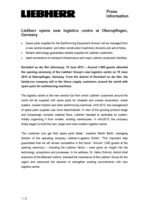
Pressinformation Liebherr opens new logistics centre at Oberopfingen, Germany∙Spare parts supplies for the Earthmoving Equipment division will be managed froma new central location, and other construction machinery divisions are set to follow. ∙Modern technology guarantees reliable supplies for Liebherr customers.∙Ideal connections to transport infrastructure and major Liebherr production facilities.Kirchdorf an der Iller (Germany), 19 June 2015 –Around 1,000 guests attended the opening ceremony of the Liebherr Group's new logistics centre on 19 June 2015 at Oberopfingen, Germany. From the district of Kirchdorf an der Iller, the family-run company will in the future supply customers around the world with spare parts for earthmoving machines.The logistics centre is the new central hub from which Liebherr customers around the world will be supplied with spare parts for wheeled and crawler excavators, wheel loaders, crawler tractors and other earthmoving machines. Until 2013, the management of spare parts supplies was more decentralised. In view of the growing product range and increasingly complex material flows, Liebherr decided to centralise its system, initially organising it from smaller, existing warehouses. In mid-2013, the company finally began to build the new, larger and more modern logistics centre.“Our customer now get their spare parts faster,” explains Martin Barth, managing director of the operating company Liebherr-Logistics GmbH. “This important step guarantees that we will remain competitive in the future.” Around 1,000 guests at the opening ceremony –including the Liebherr family –were given an insight into the technology, proportions and processes. In his address, Dr. Heiko Schmid, district chief executive of the Biberach district, stressed the importance of the Liebherr Group for the region and welcomed the decision to strengthen existing commitments with new logistics centre.Fully automated material flow and maximum supply reliabilityThe new central warehouse has an area of 47,000 m² – about the size of six football pitches – space for about 100,000 different spare parts for the Earthmoving Equipment division. Parts are taken into and out of stock in the automatic warehouse areas - which can be up to 36 m high - by energy-efficient operating machines. The responsible persons at Liebherr-Logistics GmbH employ extremely short throughput times: “Our modern warehouse technology and order picking systems make it possible to ship 1,600 individual orders to many European countries – almost all of them on the day the order is received,” explains Martin Barth. Redundant IT systems, the ability to conduct preventative maintenance work during ongoing operations and modern fire prevention measures guarantee maximum supply reliability.Strategically important location, best transportation connections and future potentialThe location at Oberopfingen was chosen deliberately. Not only is the site directly next to the A7 autobahn, it is also in the immediate neighbourhood of the major production site for Liebherr earthmoving machines at Kirchdorf an der Iller. Other plants from the construction machinery and components divisions in France, Austria and Switzerland are also not far away. “We consi dered, analysed and evaluated various locations for the warehouse,” Martin Barth continues. “In the end, Oberopfingen was the favourite.” In the final expansion phase in a few years time, the site should grow to a total of 360,000 m², or more than 50 football pitches, and hall space will be created to secure the logistics processes for the decades ahead. In the long term, the Liebherr Group is planning to merge the spare parts logistics of other construction machinery divisions in Oberopfingen.Captionsliebherr-logistics-centre-1-300dpi.jpgThe new Liebherr logistics centre at Oberopfingen near Kirchdorf an der Illerliebherr-logistics-centre-2-300dpi.jpgMartin Barth, managing director of Liebherr-Logistics GmbH (right), and logistics manager Kilian Ribheggeliebherr-logistics-centre-3-300dpi.jpgManual warehouse area and shipping at the new Liebherr logistics centre at Oberopfingenliebherr-logistics-centre-4-300dpi.jpgSpare parts are automatically moved on roller conveyors.Contact personKristian KüppersCorporate CommunicationPhone: +49 7351 41-2708E-mail:******************************Published byLiebherr-International Deutschland GmbHBiberach / Riss, Germany。
迪利尔直驱油润螺栓压机MCFRC100、102A、103、108、109、107和113的操作说明书
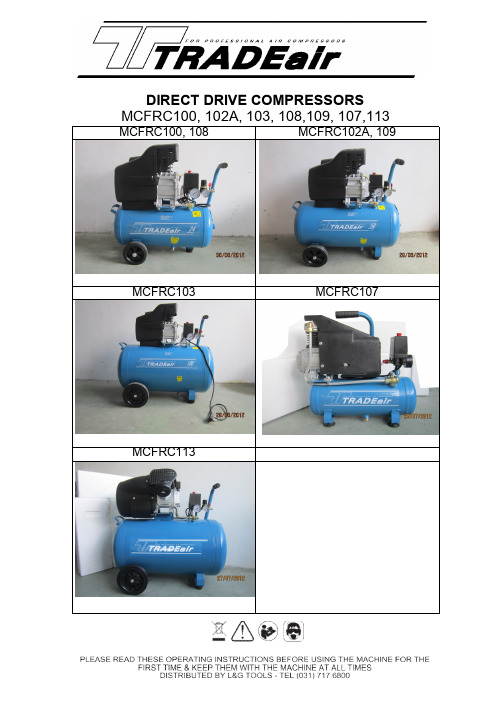
DIRECT DRIVE COMPRESSORS MCFRC100,102A,103,108,109,107,113 MCFRC100,108MCFRC102A,109MCFRC103MCFRC107MCFRC113--------------------------------------------------------------------------------------------------------------Operation Instruction of Direct Drive Oil-Lubricated Piston Compressor MCFRC100,102A,103,108,109,107and113 Protect yourself and others by observing all safety information,warnings,and cautions.Failure to comply with instructions could result in personal injury and/or damage to product or property.Please retain instructions for future reference.WARRANTYThe Supplier warrants to the original purchaser only;this power tool to be free from defects in material and workmanship.Subject to certain exceptions,the Supplier will repair or replace any part on an electric power tool which,after examination,is determined to be defective in material or workmanship for a period of one(1)year after the date of purchase unless otherwise noted.Return of the power tool to the Retailer,is required together with the proof of purchase should be included with the returned product.This warranty does not apply to damage that is determined to be from repairs made or attempted by anyone other than authorized agents,misuse,alterations,abuse,normal wear and tear,lack of maintenance,or accidents.This warranty does not include items considered as consumables.Statutory RightsThis warranty is in addition to and in no way affects your statutory rights. SPECIFICA TIONSPart No.MCFRC100MCFRC108MCFRC102AMCFRC109MCFRC103MCFRC107MCFRC113Voltage230V/50HZ230V/50HZ230V/50HZ230V/50HZ230V/50HZ Tank capacity24Litre50Litre100Litre6Litre100Litre Rated Speed2850RPM2850RPM2850RPM2850RPM2850RPM Current 5.5A 6.5A 6.5A 5.5A 6.5A Pumpdisplacement150L/MIN206L/MIN206L/MIN130L/MIN315L/MINMax Pressure 800kPa/8Bar800kPa/8Bar800kPa/8Bar800kPa/8Bar800kPa/8BarOutlet1x1/4"1x1/4"1x1/4"1x1/4"1x1/4"--------------------------------------------------------------------------------------------------------------GENERAL SAFETY INSTRUCTIONSBefore attempting to operate this compressor the following basic safety precautions should always be taken to reduce the risk of fire,electric shock and personal injury.It is important to read the instruction manual to understand the application,limitations and potential hazards associated with any tool.They are designed for the safety of yourself and others,ensuring a long and trouble free service life from your machine.Work AreaWorkbenches should be kept tidy because cluttered benches and work areas invite accidents. Floors should be kept clean and free from rubbish.Special care should be taken if the floor is slippery due to sawdust or wax.Work EnvironmentKeep the work area well lit.Do not use compressor in areas where there is a risk of explosion or fire from combustible materials,flammable liquids,e.g.,paint,varnish,petrol etc or flammable gases and dust of an explosive nature.Guard Against Electric ShockDo not expose your compressor to rain,or use in damp or wet locations.Beware Children and PetsChildren and pets should be kept out of the work area.Use the right toolSelect the right tool for the job.Do not use a tool for a job for which it was not designed.Do not force a small tool to do the job of a heavy-duty tool.Personal safety ClothingDo not wear loose clothing,jewellery or anything that could get caught in moving machinery. HairLong hair should be tied back or contained in a protective covering.Eye ProtectionAlways use protective safety goggles or safety glasses.Ear ProtectionEar protection is advised during periods of extended operation.FootwearWhere there is a risk of heavy objects damaging feet or if there is a risk of slipping on wet or slippery floors suitable non-slip safety footwear should be worn.--------------------------------------------------------------------------------------------------------------Secure the Work PieceWherever possible secure the work piece using clamps or a vice.It is safer than using your hand and leaves both hands free to control the air tool.Do Not Over-reachDo not over-reach,keep proper footing and maintain your balance at all times.Maintain Tools with CareKeep cutting tools sharp and clean for better and safer performance.Follow the instructionsfor lubricating and changing accessories.Check the tool power cord periodically and if damaged have it replaced by an authorized service facility.Keep handles dry,clean and free from oil and grease.Ensure that ventilation slots are kept clean and free from dust at all times. Blocked ventilation slots can cause overheating and damage to the motor.Stay AlertWatch what you are doing,use common sense,and do not operate the air tool when youare tired or have taken medication that causes drowsiness,consumed alcohol or drugs. General Warnings for compressors•Do not attempt to modify the compressor in any way.•The use of any tools or accessory other than those designed for use with compressed air could result in injury to the operator.•The output pressure of the compressor should be adjusted to the design pressure of the air tool or accessory being used.•Always check that the output of the compressor does not exceed the maximum pressure for any attached tool or accessory.•Repairs should only be carried out by qualified persons using original spare parts.Failure to do so may result in considerable danger to the user.Breathable Air WarningThis compressor/pump is not equipped for,and should not be used to supply breathing quality air for any application of air for human consumption.Overload protection.This compressor is fitted with an overload protection device.In the event that the motor becomes too hot,a thermal protection device will cut the mains supplyto the motor.When the motor temperature returns to normal the mains supply will berestored automatically.Extension Cords and ReelsIn general,it is not recommended to use an extension lead.A longer air line is recommended as voltage drop on extension leads may lead to motor damage and will void warranty.If an extension cord must be used,for lengths up to5metres,an approved15amp rated cord must be used.--------------------------------------------------------------------------------------------------------------Do Not Abuse the Power CordNever yank or pull on the power cord to disconnect it from the mains supply socket.Never carry or drag your compressor by its power cord.Keep the power cord away from heat,oil, solvents and sharp edges.If the power cord becomes damaged have it replaced by an authorized service facility.Check Damaged PartsBefore using the compressor it should be carefully checked to determine that it will operate properly and perform its intended function.Check for the correct alignment of moving parts ensuring they do not bind.Check for broken or missing parts and have them replaced or repaired at an authorized service centre.Check any other condition that may affect the operation of the compressor.A guard or any other part of the compressor that is damaged should be properly repaired or replaced by an authorized service centre.Disconnect CompressorEnsure that the compressor is disconnected from the mains supply and the tank is empty when not in use,before servicing,lubricating or making adjustments to air lines,and when changing accessories such as blades,bits,nails and cutters on air tools.Avoid Unintentional StartingEnsure that the switch is in the OFF position before plugging the compressor into themains supplyTurning the compressor ON and OFFUse the red knob on top of the pressure switch to turn the unit on and off.Pull the knob upto turn the compressor on and push the knob in to turn it off.Turning the unit on and off from the mains supply only will result in damage to the motor and void warranty as the pressure switch has an additional function to purge the air trapped in the delivery pipe when themotor is turned off.This minimises the load on the motor when it is next started.--------------------------------------------------------------------------------------------------------------GENERAL VIEW AND MAIN COMPONENTS1.Main Compressor2.Pressure Switch3.Outlet Valve4.Pressure Regulator5.Pressure Gauge6.Non-Return Valve7.Drain Cock8.Wheel9.Discharge Pipe10.Air Tank 11.Safety Valve12.Fan CoverNote:Fittings may differ from those shown above.112435678910121--------------------------------------------------------------------------------------------------------------ASSEMBLYThis air compressor requires some minor assemble before it can be used.Locate the accessory pack.It should contain:1.Wheels and axle set2.Rubber stopper3.Air Filter4.Oil Breather plug5.A bottle of oil•Fit the wheels to the unit using the axlekit provided and insert the rubber stopper into thespigot on the bottom of the tank.•Fit the air filter to cylinder head of the compressor.•Locate the plastic dust plug in the oil breather hole and remove it to expose the oil breather hole.Oil breather hole--------------------------------------------------------------------------------------------------------------Oil Warning:This unit is shipped with oil in the compressor pump.•Usually check the oil level in the pump.Please fill the oil from the oil breather hole until the oil reaches the red mark on the sight glass•Check that the small hole in the top of the breather pipe is clear and then insert it into the oil filler hole.NOTE:The oil must be changed after the first10hrs of operation then every20hrs thereafter.Recommend compressor oil:Use SAE30for temperatures over10℃and use SAE10below10℃.--------------------------------------------------------------------------------------------------------------INITIAL ST ARTUP•Ensure the unit is stable in a well-ventilated dry position.•Ensure that the drain valve is closed and all air outlets are closed.Connect the power lead to the mains.•Start the compressor by pulling on the red knob.•Check for air leaksNote:Output fittings may differ from those shownWarning :Use the red knob to turn the unit on and off,not the mains switch.Turning the unit on and off from the mains only will result in damage to themotorTurn off--------------------------------------------------------------------------------------------------------------OPERATIONThe pressure in the tank is controlled by the action of the pressure switch located under the pressure switch coverWhen the set maximum pressure is reached the pressure switch activates and the motor is turned off.The pressure will then decrease as the air is used until the set minimum is reached after which the pressure switch turns the motor on again.The operator of the compressor should be well aware that during use of the compressor the motor will cycle (start and stop)under the influence of the rising or falling pressure in the tank and the motor will start without any warning.The maximum and minimum pressures are factory set and should not be altered.You can utilize either the direct outlet and/or the regulated outlet.The pressure of the regulated outlet can be changed by turning the control knob.Rotate the knob clockwise to increase pressure and anti-clockwise to decreaseNote:Output fittings may differ from thoseshownTurn off--------------------------------------------------------------------------------------------------------------MAINTENANCEWarning:Before maintenance operation,stop the air compressor,disconnect the unit from the mains supply and discharge all air in the air tank.Daily1.Check oil level before each use.2.Drain the condensation from the air receiver.3.Check for air leaks.Weekly1.Remove air filter element and clean or replace as required.Monthly1.Inspect non-return valve(clean or replace as required)Caution:ensure that air the tank is empty for this operation.2.Manually test the safety valve by pulling the ring.Three Monthly1.Change Oil2.Tighten cylinder head bolts.3.Clean and check valve assembly,replace gaskets/valves if worn or damaged.Recommend compressor oil use SAE30for temperatures over10℃and use SAE10 below10℃.--------------------------------------------------------------------------------------------------------------TROUBLES AND REMEDIESTrouble Possible causesRemedies Motor unable to run or running slow ⑴Fault in line,or voltage insufficient⑵Power wire too thin or too long⑶Fault in pressure switch⑷Fault in motor⑸Sticking of main compressor⑹The inner thermal protector on motor cut off ⑴Check the line ⑵Replace the wire ⑶Repair or replace ⑷Repair or replace ⑸Check and repair ⑹Compressor works too hard,turn offthe power and wait for 10-15minutes tocool down motor and restart.Sticking of main compressor ⑴Moving parts burnt due to insufficient oil ⑵Moving parts damaged,or stuck by foreign body Check crankshaft,bearing,connectingrod,piston,piston ring,etc.and replaceif necessaryExcessive vibration or abnormal noise ⑴Connecting part loose ⑵Foreign body got into main compressor ⑶Piston knocking valve seat ⑷Moving parts seriously worn⑴Check and retighten⑵Check and clean away⑶Replace with thicker paper gasket⑷Repair or replace Pressure insufficientor dischargecapacity decreased ⑴Motor running too slow ⑵Air filter choked up ⑶Leakage of safety valve ⑷Leakage of discharge pipe ⑸Sealing gasket damaged⑹Valve plate damaged,carbon build up or stuck⑺Piston ring and cylinder worn or damaged ⑴Check and remedy ⑵Clean or replace the cartridge ⑶Check and adjust ⑷Check and repair ⑸Check and replace ⑹Replace and clean ⑺Repair or replaceExcessive oilconsumption ⑴Oil level too high ⑵Breath pipe choked up⑶Piston ring and cylinder worn or damaged ⑴Keep the level within set range ⑵Check and clean ⑶Repair or replacePART LIST OF DIRECT DRIVE COMPRESSOR24L: MCFRC100,108; 50L: MCFRC102A,109; 100L: MCFRC103OTS VERSION: 10TH,MARCH,2012 QTY QTY 1Bolt M8×105430Spring washer 54 2Cylinder head131Bolt M5×954 3O Ring132Circlip Φ141 4Valve plate133Motor Fan1 5Inlet valve134Screw M4×101 6Locating pin Φ3×6235Tooth washer 41 7Valve gasketδ0.8136Screw M3×62 8A CylinderΦ42 for MCFRC100,108137Spring washer 32 8B CylinderΦ48 for MCFRC102A,109,103138A Capacitor 15UF for MCFRC100,1081 9Cylinder gasket δ0.8138B Capacitor 30UF for MCFRC102A,109,1031 10Bolt M12×15139Tooth washer 81 11A Piston ringΦ42 for MCFRC100,108140Air filter1 11B Piston ringΦ48 for MCFRC102A,109,103141Right-angle connecter Rp3/81 12A PistonΦ42 for MCFRC100,108142Fan cover1 12B PistonΦ48 for MCFRC102A,109,103143Screw M5×102 13A Piston Pin for MCFRC100,108144Screw ST3.4×162 13B Piston Pin for MCFRC102A,109,103145Handle Grip1 14CirclipΦ12246One-way valve1 15A Connecting rod for MCFRC100,108147Bolt M8×254 15B Connecting rod for MCFRC102A,109,103148Nut M84 16Breath pipe149Discharge Pipe1 17Screw M5×14650Discharge gasket2 18Oil leveler M27×1.5151Tank 36liter 1 19Crankcase cover152A 4.5" wheel kits for MCFRC100,1082 20Rubber gasket152B6" wheel kits for MCFRC102A,1092 21Screw M8×22-left152C8" wheel kits for MCFRC1032 22A Crank 17.5mm for MCFRC100,108153Drain Valve 1 22B Crank 20mm for MCFRC102A,109,103154Rubber foot kit2 23Crankcase155Release pipe1 24Sealing ring 20×40×7156south africa Power cord1 25Bearing 6204-2RZ1571/4" need valve with nut1 26A Rotor for MCFRC100,1081581/4"-1/4" mini regulator1 26B Rotor for MCFRC102A,109,10315940mm rear gauge2 27Bearing 6202-2RZ1601/4" -1/4"connector2 28A stator for MCFRC100,10816150mm rear gauge28B stator for MCFRC102A,109,1031628Bar 4 way 1/4" pressure switch1 29Motor bracket1631/4",8Bar safety valve1MCFRC107 PART LIST Unit QTY Unit QTY1 Bolt M6×35PC434 Spring Washer 4PC12 Spring Washer 6PC835 Screw M4×8PC13 Cylinder head PC136 Spring Washer 5PC44 Cylinder Head Sealing PC137 Bolt M5×80PC45 E-Bow Connector PC138 Clip Φ14PC16 Valve Plate SET139 Fan PC17 Inlet Valve PC142 Plastic Bottom cover PC18 Valve pin PC243 Fan cover PC19 Valve Gasket PC144 Screw M4×8PC410 Helx Bolt M6×20PC445 Bolt M5×16PC411 Cylinder PC146 Capacitor PC112 Cylinder Gasket PC148 Tooth Washer 8PC113 Piston Ring Set SET149 Nut M8PC115 Piston PC150 Air Filter PC116 Hole Clip Φ12PC251 Handel Grip PC117 Piston Pin PC152 Discharge Pipe SET118 Connect Rod PC153 Bolt M8×30PC419 Oil Breather PC154 Nut M8PC420 Oil Leveler PC155 Pressure Tank 6LT PC121 Bolt M5×16PC456 Pad SET422 Crankcase Cover PC157 Drain Valve PC123 Crankcase Sealing PC158 Check Valve SET124 Molt M10 for Crank PCS159 Release Pipe SET125 Crank PC160 Outlet Valve PC126 Crankcase PC161 Regulator PC127 Oil Sealing PC162 Pressure Guage 40PC128 Bearing 6003-2RS PC163 Connector R1/4PC129 Motor PC164 Power cord PC130 Stator SET165 Safty Valve PC131 Bearing 6202-2RS PC166 Pressure Switch PC132 Motor Bracket PC167 Pressure Guage 50PC133 Tooth Washer 4PC1MCFRC113 PART LISTNOPart Unit Qty NO Part Unit Qty 1Bolt M8x40PC 837fan PC 12cylinder head PC 238circlip Φ20PC 13O Ring PC 239Main cover PC 14valve plate subassembly SET 240Srew M5x14PC 45valve slice δ0.3PC 241Srew M3x6PC 46locating pin Φ3×6PC 442Spring washer 3PC 47valve gasket δ0.8PC 243Starting capacitance PC 18cylinder Φ42(Φ47)PC 244Running capacitance PC 19bolt M8x25PC 445Srew ST 3.9x15PC 310Spring Washer 8PC 446Head cover PC 111cylinder gasket δ0.8PC 247Cover support PC 112piston ring Φ42(Φ47)SET 248nut 8PC 213piston Φ42(Φ47)PC 249Air filter SET 214piston pin Φ12×35(38.5)PC 250Connect pipe SET 115circlip Φ14PC 451Tree-way connector A PC 116connecting rod PC 252Tree-way connector B PC 117breath pip SET 153Leak valve PC 118crankcase cover PC 154right-angle connector PC 119oil leveler SET 155Discharge Pipe PC 120bolt M5x16PC 556release pipe SET 121rubber gasket PC 157check valve PC 122screw M8×20PC 158Tank PC 123enlarge washer 8PC 159Bolt M8x40PC 424crank PC 160nut 8PC 425crankcase PC 161wheel assembly SET 226sealing ring 24×47×8PC 162handle grip PC 127brearing 6205PC 163drain valve SET 128rotor SET 164 foot pad assembly SET 229stator SET 165Outlet Valve SET 130screw M4×10PC 266Regulator PC 131Centrifugal switch L22SET 167Conector R1/4PC 132brearing 6204PC 168Power cord 3G1.5mm2PC 133motor bracket PC 169Pressure Guage 40mm PC 134Tooth Wahser 4PC 170Safety valve 1/4" 9Bar PC 135spring washer 6PC 471Pressure switch 8Bar PC 1Distributed by L&G Tool&Machinery Distributors Limited6Kyalami Rd,Westmead3610,P.O.Box15313,Westmead3608,Telephone:031-7176800,Fax:031-7176868。
模具(弯管)技术要求V1_试行文件01

技术要求一.弯管机技术规格二.弯管模具安装及调试弯管模具安装示意图图(1)轮夹安装:将轮夹放入轮模安装处,锁紧固定螺丝(中间若有定位键先研配定位键),轮夹与轮模的拼接要求零缝隙,全接触,无高低落差感。
(2)轮模安装:以逆时针方向将轮模固定螺母取下,放入轮模,再将轮模固定螺母锁紧。
(3) 夹模安装:拉出夹模固定座。
将夹模放入对准燕尾槽插入即可。
调整:1.将夹模座固定放松,再将控制面板置于手动模式,按下夹管按钮,至夹模行径终点。
(此时在轮模夹模间需有间隙,可以夹模座调整螺杆来调整)。
2.调整夹模座调整螺杆使夹模与轮模完全密合。
3. 按下退夹按钮使夹模后退,再将夹模调整螺杆顺时针方向旋转约1/2-1/4圈,锁紧螺母。
(4)导模安装:将导模座固定螺丝取下,再将导模放入,研配两平行槽及其平面,然后螺丝锁紧即可。
调整:1.将导模座固定螺母放松,再将控制面板置于手动模式,按下夹管按钮至导模行径之终点(此时在轮模与导模间须有间隙,可以用导模调整螺杆来调整。
2、调整导模座调整螺杆使导模与轮模完全密合。
3.按下退夹按钮,再将导模调整螺杆顺时针方向转约1/2-1/4圈。
4、再将导模座固定螺丝锁紧即可。
(5)后导模安装:拉出后模固定座,将后导模放入研配平行键,然后螺丝锁紧即可。
后导模与轮模配合要求型面对接光顺,配合面无间隙。
(6)芯棒安装:将芯棒以顺时针方向放入穿心杆。
再将芯棒固定螺丝固定即可。
注意芯棒须配合弯管弯曲的方向(7)束管夹安装:将穿心杆以逆时针方向取下,然后将束管夹固定螺丝锁紧即可。
意大利COMERIOERCOLE公司_S_形四辊钢丝压延机的自动控制原理
意大利COMERIO ERCOLE 公司“S”形四辊钢丝压延机的自动控制原理文峰,迭华,陈飞 (贵州轮胎股份有限公司全钢分公司,贵州贵阳 550008)摘要:从生产工艺的角度,将钢丝压延机的控制系统分成张力控制系统、厚度控制系统、辅助系统等三大部分,论述各部分功能及自动控制原理。
关键词:钢丝压延机;张力控制系统;厚度控制系统;上位机;工控机;PLC中图分类号:TQ330.44 文献标识码:B 文章编号:1009–797X(2002)02–0051–04在全钢子午线轮胎的生产设备中,钢丝压延机以其生产精度要求高,控制系统复杂,生产能力大等特点,占据了很突出位置,是全钢子午线轮胎的关键生产设备之一。
从生产工艺的角度来看,压延机的控制系统可分成张力控制系统,厚度控制系统,辅助系统等三大部分。
张力控制系统由钢丝锭子张力控制装置、生产线直流拖动系统及贮布架液压系统等构成;厚度控制系统由厚度测量系统、辊距调节系统、辊弯曲及轴交叉构成;辅助控制系统由温度控制系统、积胶控制系统、卷取定中装置、压延机润滑系统、主机压力辊伺服控制等构成。
下文将围绕这三大系统展开论述。
限于篇幅,本文只讨论压延机的自动工作模式。
1 控制系统构成我公司引进的意大利Comerio Ercole公司“S”形四辊钢丝压延机,其自动控制系统由上位机、测厚系统工控机、西门子S7-300型PLC构成(见图1)。
2 张力控制系统压延机张力控制的好坏,是影响钢丝帘布质量的重要因素之一。
因此,在整个控制系统中张力控制系统占据了较大的比重。
以主机3#辊为准,可将压延机的张力控制分为压延前和压延后张力控制。
压延前张力由美国RJS 公司提供的气动式张力控制装置控制,通过手动调节压缩空气回路的减压阀来控制钢丝锭子的导开张力。
压延后张力控制分为三段,由上位机和PLC 控制。
2.1 冷却辊段张力该段张力是由冷却辊直流电机和主机3#辊直流电机的设定速度差产生的。
当然,由于钢丝的伸长率很小,因此如忽略钢丝的伸长变形和传动机构的打滑现象,压延生产线各点的实际线速度是一致的,均等于钢丝的导开速度。
耐克迪玛机械有限公司产品说明书

The Winning ForceThe Winning ForceAs a total supplier for sheet metal manufacturing with almost60 years of experience, Durma understands and recognizes thechallenges, requirements and expectations of the industry.We strive to satisfy the ever higher demands of our customers bycontinuously improving our products and processes whileresearching and implementing the latest technologies.In our three production plants with a total of 150.000 m²,we dedicate 1,000 employees to delivering high qualitymanufacturing solutions at the best performance-to-price ratioin the market.From the innovations developed at our Research & DevelopmentCenter to the technical support given by our worldwidedistributors, we all have one common mission: to be yourpreferred partner.Present Durmazlar machines with name to the world.High technology,modern productionlinesHigh qualitymachines designedin R&D CentreTop qualitycomponents123Now Production is More EffectiveThe future – as a result of rising energy costs and increasingly cost efficient speed-controlled drives offered on the market, variable-speed solutions are on the advance.AD-Servo Series Press BrakeEnergy-efficient Hydraulics with Variable Speed Pump DrivesEnergy consumption has a significant effect on Total Cost of Ownership of plant and machinery:even with standard machines, the energy consumption represents 30% of total costs, and with particularly energy-intensive applications, this share is remarkably higher.Cost Down Profit UpAdvantagesHigh energy-saving potential Decreased operating costs Clearly reduced cooling effort Operational reliability High availability Lower investment System safetyFuture-oriented technology Remarkable noise reduction Fewer secondary measuresEase of integration of flexible check functionsDecrease in the number of expensive machine failures Compliance with EU DirectivesPrecise bending result at fast speedMinimalized tool change and adjustment time Maximized speed and safetyHigh Capacity Winning ErgonomicRobust Body Perfect PrecisionHighCapacity Low Power ConsumptionEnergy Saver Accurate on each cycle Economy ProofHi-Speed & RepeatabilityComparison of EnergyConsumption of aPress BrakesMain componentsServomotorHydromotor-pump (4-quadr. oper.)Servo controller IndraDrive CSoftware-Technology functionParameterBell housing and couplingPower unit (Oil tank, accessories)Valve block, prefill valveCylinderPhysical characteristicsControl of positionControl of pressure/load pressureOpen/closed hydraulic circuit4-quadrant operationProductivity%60 more productivity with %72less energy consumption at work.AD-Servo positioningaccuracy Less Noise Levelat target positionFast Increase in Efficiency inProductionAD-Servo is high modularity of hydraulics also opens upeconomic options on existing plant and machinery bysubstituting fixed displacement power units byvariable-speed pump drives with little effort.0.000 2.000 4.000 6.0008.00010.00012.00014.000kWhRegular Press BrakesAD-Servo Press BrakesEnergy SavingCost Down Profit UpElectric ConsumptionDepending on cycle characteristicsand rating, variable-speed pumpdrives achieve energy savingsLess Noise LevelWhy DURMA Back Gauge ?Most important feature toachieve perfect bending is the stability and the design of the back gauge, which allows an impeccable and correct product to be produced.The high speed ballscrew back gauge system movement is also supported with linear guides,which helps the back gauge achieve long life, greater sensitivity and strengthens against any collisions.Special designed finger blocks with steps to achieve maximum stability can also be supplied for every kind of bending solution.High sensitivity, Stress relieved steel construction body, long life Mono Block Frame Automatic calibration and first start upDURMA designed and copyrighted guiding systemBall Screw and linear guide integrated perfect back gauge system Durable, long life and sensitive bending capable special hardened top tools Suitable for segmented tools special and fast tool holding system Sensitive solutions on long and deep bending High accuracy linear scales CE safety standardsBest quality world wide accepted hydraulic and electric componentsStrong Back Gauge SystemPrecise Reliable StrongFast and high accuracy Safe movement Resistance to crash Maintenance freeAdjustment availability at every pointFast, Efficient, ModernCNC optional back gauge X - RX - R - Z1, Z2X - R - Z1, Z2, Delta XXXZ1ZZ2RRCNC optional back gauge X1 - X2, R1 - R2, Z1 - Z2X2X1R1Z2R2Z12, 4, 5 or 6Axis Back GaugeCE Safety SystemModEva 15 T Control UnitTop BeamLED IlluminationCNC CrowningLinear Guided Front Support ArmsHydraulic SystemAD-Servo Series press brakes, designed with high technology to increase efficiency on precise part bending.Quality approved components used.Stress relieved made on bodies for long life and precise bending.General SpecificationsCNC back gauge X - R Z manuelTool Holders and ToolsBending performance increased using with high quality European clamping system and easy to use. Narrow table designed for European style tool holder and Z bending.DURMA is your solution partner with various tool options.European Clamping SystemWila Top Tool ClampingWila Bottom Tool ClampingEuropean Type Bottom Tool (4V Die)DURMA Multi V Bottom ToolDURMA Top ToolQuick Release ClampingManual or CNC-controlled motorized crowning system simplifies bending, by adjusting each point of the bending parts to acquire straight bends. The need for shimming is eliminated.Crowning SystemCNC Crowning SystemOur machines are designed in accordance with Ce-Norms to ensure your safety with hydraulic, electric, appropriate height covers and laser light curtains. CE safety in tandem machines are also provided with light barriers.CE Safety SystemsBy using long and planar guiding surfaces, all thedisadvantages of point guiding are eliminated 100% free bending space: guiding system that eliminates bending between frame has been moved to the outside of the frame.Stable Top Beam MovementLinear Guide Front Sheet SupportsRugged support arms with tilting stops are mountedon a linear guide rail system. This allows “finger-tip” lateral adjustment as required by the bend length of the part. They are also equipped with side gauges for the fast, easy, and accurate feeding of parts small or large.Linear Guide Front Sheet SupportsSafe and Accurate Bends with Top Quality EquipmentsFull 3D simulationMultiple view points while working3D collision detectionUser defined table for bend deduction Rapid solution computationImporting 3D models (MetaBEND, IGES) Automatic Tool Shape SelectionVideo-like bend simulation.Almost unlimited quantity of programs and sequences Higher grade of efficiency3D and 2D graphical touch screen programming mode 17" high resolution colour TFTMinimal set up timeDelem modusys compatabilitySensor bending correction interface1 GB memory capacityIntegrated OEM-Panel1280x1024 pixels, 16-bit colour3D graphics accelerationNow Bending is More Easier15" color Touch ScreenOn-screen finger profile drawingAutomatic bend listingVery simple and convenient data transferHigher productivity thanks to easy and rapidMulti-simulation capabilitySimulation criteria for better sheet management Windows XPe for multitasking and file management EC safety-cycle managementEthernet for easy communicationBundled Offline Software 2D graphical touch screen programming mode3D visualisation in simulation and production17" high resolution colour TFTFull Windows application suiteDelem modusys compatibilityUSB, peripheral interfacingUser specific application support within the controllers multitasking environmentSensor bending & correction interfaceModEva 15TModeva PremiumDA-69TDA-66T DURMA ANGLE MEASUREMENT AP3 - AP4 SHEET FOLLOWERROBOTIC SOLUTIONSStandard EquipmentY Y1, Y2, X, R (4-Axis) X=650mm X,R (AL - double gayt )DBEND 3D CAD/CAM Importing & Similation Program Control Unit - CNC ModEva15T or 66TCE BLVT safety – only for tandem machinesServo motor back gauge & linear guided & ballscrew system (X-R)CNC crowningEuropean style tool clamping systemSliding front arms (With T-Slot and stopper)World standards special design hydraulic block and valves World standard electric equipmentOptional EquipmentControl unit - ModEva Premium or 69TCE Manuel F. AKAS II M FPSC-B-C + safety covers with switch CE F. AKAS-LC II AKAS-3 M Motorized + FPSC (safety PLC)CE BLVT safety – only for tandem machines Z1, Z2 axis X1, X2 axis R1, R2 axisDelta X axis ± 125 mm with CNC Controlled X axis = 1000 mm – light barrier back protection AP3-AP4 sheet following systemHeight adjustable laser angle measurement system Quick release clamping systemHydraulic and pneumatic tool clamping systems Bottom and top toolsBottom tool separation system Parking areaCentral lubrication system Oil coolerAdditional back gauge finger and sliding front support arms Special packing for overseas shipmentsStandard & Optional EquipmentConsultancy Spare PartsR&D CenterServiceAgreementsTrainingAfter Sales ServiceSoftware Flexible SolutionSolution CenterDURMA provides the best level of service and spare parts with qualified personnel and spare parts in stock.Our experienced and professional service personnel are always ready at your service. Our professional training and application enriched courses will give you an advantage to use our machinery.Fast on Service and Spare PartsAD-Servo Serisi Teknik DetaylarS : Standard O : Option* 750 mm throat depth** 750 - 1000 - 1250 mm throat depthMachines set according to optimum values.Durmazlar Makina San. ve Tic. A.Ş.OSB 75. Yıl Bulvarı Nilüfer-Bursa / Türkiye P: +90 224 219 18 00 F: +90 224 242 75 80******************.tr .trEN_2018/04/V06。
埃马克机床(太仓)有限公司CIMES2008期间推出新品
会
”
年全 国 电火 花 成 形 加 工 技 术研讨 在北 京电加 工 所举行
2008
)1
”
20 0 8年l o
10
~
12
日
“ ,
2 0 0 8 年全 国 电火 花成 形 加
。
加 快本 土 化 经 营 美 卡 诺 再 次起动 厂 房 扩建 工 程
继 2 0 0 8 年 3 q 新 厂 房扩 建 竣 工 后
、
会
司将于 2 0 0 8 年 1 1 月再 次起 动厂 房扩 建 工 程
2 0 0 9 年 10
预计 将于
议 由 中 国机 械 工 程 学 会 特种加 工 分 会 副 理 事长
电火 花
成形 加 工 技 术委 员会 主任曹凤 国主持
北 京 市科委副 主任
、
。
月竣 工
。
。
届时
,
生 产车 间的面 积将 从 原 有的
致
。
乞 - 套 简采 用 了静 压 轴 承 鸳 由
m
,
,
主 轴前端轴 承的直径达
,
到 16 0 m
二
刀 塔 采 用 了V D I 5 0 标 准 的 刀 柄
所有 这 些
。
产权 的
“
C A D
“
平 台+
次开发
,
软 件 解决 方 案
,
并纷 产业
都充 分保证 了钻铣 时机床的稳定性 和减 振 效 果
送 采 用 L 形 工 件输 送 料 道 和 柔 性 拖 架 过一
,
,
工 技术 研讨 会
在北 京 市科学 技 术研 究院 报告厅 举行
、
美卡 诺 元 器 件
Hypertherm FLEXCUT 125 CE 产品说明书

Powerful 125A Air PlasmaFLEXCUT ™ 125 CESteel Fabrication, Pipe Cutting, Structural Publication 04/17© LINCOLN ELECTRIC Cutting Solutions All Rights Reserved www.lincolnelectriccutting.euCE conformCUSTOMER ASSISTANCE POLICYThe Lincoln Electric Company is manufacturing and selling high quality welding equipment, consumables, and cutting equipment. Our challenge is to meet the needs of our customers and to exceed their expectations. On occa- sion, purchasers may ask Lincoln Electric for information or advice about their use of our products. Our employees respond to inquiries to the best of their ability based on information provided to them by the customers and the knowledge they may have concerning the application. Our employees, however, are not in a position to verify the information provided or to evaluate the engineering requirements for the particular weldment. Accordingly, Lincoln Electric does not warrant or guarantee or assume any liability with respect to such information or advice. Moreover, the provision of such information or advice does not create, expand, or alter any warranty on our products. Any express or implied warranty that might arise from the information or advice, including any implied warranty of merchantability or any warranty of tness for any customers’ particular purpose is speci cally disclaimed.Lincoln Electric is a responsive manufacturer, but the selection and use of speci c products sold by Lincoln Electric is solely within the control of, and remains the sole responsibility of the customer. Many variables beyond the control of Lincoln Electric a ect the results obtained in applying these types of fabrication methods and service requirements.Subject to Change – This information is accurate to the best of our knowledge at the time of printing. Please refer to for any updated information.FLEXCUT ™ 125 - Specifications10009008007006005004003002001000635050803810254012700125A CuttingFLEXCUT 125FLEXCUT 125125A-12 mm Mild Steel105A-12 mm Mild Steel 45A-2 mm Mild Steel105A CuttingCompetitorCompetitorN u m b e r o f p i e r c e s p e r E l e c t r o d e (20 s e c . C u t T e s t )D r o s s A r e a i n m m 2C u t S p e e d (m m / m i n)ELECTRODE LIFE COMPARISON *CUT QUALITY COMPARISONS *43,93,83,73,63,53,43,3FLEXCUT 125CompetitorB e v e l A n g l e i n D e g r e e sEdge Bevel, 125A, 12 mm Mild SteelDross Level, 125A, 12 mm Mild SteelEdge Profile, 125A, 12 mm Mild SteelCUT SPEED COMPARISON *Lincoln Electric CompetitorFLEXCUT TM 125 CE offers you:Longer Consumable Life • Faster Cut Speeds • Less Edge Bevel • Better Cut Quality and Performance*Claims based upon tests conducted by LINCOLN ELECTRIC in 2016 using an LC125M TorchLess Desired 4° Edge BevelDesired 0° Edge BevelXPLINCOLN ELECTRIC DEUTSCHLAND ZNL der Lincoln Smitweld B.V., Nijmegen Werkstrasse 5 • 64732 Bad Koenig • DeutschlandT: +49 6063 57721 0E-Mail:**************************************www.lincolnelectriccutting.eu1,991,931,871,801,741,671,611,550,1650,1630,1600,1570,1550,1520,1500,1470,1450,1420,140E d g e S u r f a c e F i n i s h i n m m。
马克特克双螺纹镀磨机操作手册及配件清单说明书

MACTECH Dual Clamshell Lathe Operating Manual & Parts List 1SAFETY INSTRUCTIONS•Wear protective clothing, including safety glasses and steel toe boots.• DO NOT allow loose clothing or long hair near machine operations.• Keep work site and machine clean. Use brush to remove chips. DO NOT use hands or air hose.• Ensure adequate clearance around pipe before mounting machine.• Support pipe for total machine weight.• DO NOT rush the job. Read this manual and understand the operating procedure beforeattempting any cutting operation. Call our toll freenumber (1-800-328-1488) if any problems arise.• Before connecting the hoses to the machine, be sure the following components are tightly secured: toolblocks, tool bits, locator pads, squaring and centeringscrews, motor mounts.• Be sure both clamshells are totally secured to the pipe before starting the machine.• During actual machine operation, DO NOT touch or rest your hand on or near any moving parts or sharpedges.• Disconnect air hose or hydraulic power source BEFORE dismounting lathe from pipe.•NEVER MOVE LATHE WHILE CONNECTED TO AIR OR HYDRAULIC SUPPLY. ALWAYS turn offcontrol valve and disconnect hoses BEFOREattempting to move the machine.MACHINE SET-UPRead SAFETY INSTRUCTIONS on Page 1.Pre-Installation ProcedureNOTE:MOTOR SHOULD BE REMOVED FROMTHE DRIVE CLAMSHELL AND TOOLBITS REMOVED FROM TOOL BLOCKSeparating The Lathe1. Rotate support cage assembly by hand until boththe gear and housing split lines on the clamshellsare aligned on each clamshell. If necessary, rotateclamshell housing on one end to properly alignthe split lines.2. Place the four (4) provided locking pins into thelock pin holes located on each gear face. One lockpin per each half on each clamshell is required toprevent gear rotation when the machine is split. Ifthe lock pin holes in the gear will not line up withthe holes in the housing, rotate the support cageassembly 180 degrees for proper alignment.3. Loosen and remove the eight (8) cap screwslocated on the tabs of the two aluminum cagesupport mounting plates. Loosen and unlatch thefour (4) swing bolts located on the two gear faces.Loosen and unlatch the four (4) swing boltslocated on the sides of the two clamshellhousings, and separate the clamshell lathe halvesby pulling straight apart.CAUTIONTO AVOID SERIOUS MACHINE DAMAGE,DO NOT PRY HALVES APARTMACTECH Dual Clamshell Lathe Operating Manual & Parts List2Setting Machine To Shaft Diameter1. Determine pipe OD and select proper locator padset. The pad adjustment set screws are accessedfrom the outside of the housing using an allenwrench. Back off all locator pads as needed forproper clearance of pipe diameter.2. Determine if present slide location will clear pipe.If not, disassemble the tool holder slide fromclamshell gear faces by removing all of themounting bolts in the gearbox housing and theslide end cap. Pull clamshell halves straight awayfrom the bar to prevent binding on the locatingdowels. Remove all of the cap screws in the slideadapter plates located on the two disassembledclamshell halves. Move adapter plates either up ordown to establish tool slide clearance whenmounted on pipe. Reassemble adapter plates, toolholder slide assembly and clamshell halves.NOTE:TOOL HOLDER SLIDE AND ADAPTER PLATESMUST BE ASSEMBLED WITH DOWEL PINS TOPREVENT UNWANTED TOOL MOVEMENT Installation on In-Line PipeJoining Clamshell Lathe Halves1. Place clamshell lathe halves around the pipe andtighten the clamping swing bolts on the sides ofthe clamshell frames and on the gear faces.Tighten swing bolts in aluminum housing beforeswing bolts on gear face. Fasten halves togethersecurely with eight (8) cap screws on the tabs ofthe aluminum cage support plates.NOTE:IF LATHE HALVES WILL NOT COMETOGETHER, CHECK LOCATOR PADS FORPROPER SIZE AND CLEARANCE – BACK OFFFURTHER IF NECESSARYMACTECH Dual Clamshell Lathe Operating Manual & Parts List32. Lightly tighten the adjustable locator pads aroundthe pipe diameter just enough to secure theclamshell. Do not tighten down completely untilthe squaring and centering operations arecompleted.3. Remove the four (4) locking pins from the gearface on both clamshells. This allows the gear torotate freely. Rotate slide and cage assembly byhand to check for smooth rotation.Centering the Lathe on the Pipe1. Using a 6" scale, measure the distance from thepipe OD to the clam ID at two positions 180degrees apart. Adjust pads until they are equaldistance while maintaining a secure fit to the pipe.Repeat on pads other pads 90 degrees apart.Procedure should be done to both ends of thelathe.2. Mount a dial indicator (not included) on the gearface of one clamshell to indicate the OD of thepipe. Rotate the gear by hand, checking forproper centering and minor adjustments as in step#1 with a dial indicator instead of scale.Attaching and Adjusting the Tripper1. Rotate slide and support cage assembly so that thetripper wheel on the gear box is perpendicularwith the tripper bracket mounting notch, which islocated on the clamshell housing closest to thegear box.2. Add proper tripper bracket extension blocks sothat tripper is low enough to make contact withtripping wheel but high enough to clear gear box.Use the appropriate caps screws provided toattach tripper block assembly.MACTECH Dual Clamshell Lathe Operating Manual & Parts List4MACTECH Dual Clamshell Lathe Operating Manual & Parts List 53. The amount of feed can be adjusted by looseningthe cap screws that are located by the adjustmentknob on the tripper block base. Turn adjustmentknob to increase or decrease the feed rate.Setting Tool BitsPrior to installation of a tool bit, determine which tool bit must be used for your specific machining operation. The following steps describe installation of tool bits for machining.1. Using the tool block thumb wheel, back tool block away from pipe to create room for bits.2. Insert proper tool bit so that the cutting tip touches the pipe OD and stems from the centerline of the pipe. Hold bit with one cap screw, snug but NOT tight.3. Rotate machine to find “high” spot in pipe,tighten screws to hold bit at this positionMACHINE OPERATIONRead SAFETY INSTRUCTIONS on Page 1.Operating1. Attach air or hydraulic supply to the motor whilecontrol valve is OFF. Put gearbox shifter in themiddle position so that it is in neutral, opencontrol valve slowly to check function and speed. Connect the air caddy between the air supply and the latheCAUTION TO PREVENT SEVERE TRIPPER MECHANISIM DAMAGE, DO NOT ROTATE MACHINE COUNTER-CLOCKWISEand adjust filter and lubricator to match operating speed.2. Engage gearbox shifter either up or down todesired feed direction, use control valve to controlcutting speed. If chatter or vibration occurs,reduce speed. If tool bit(s) chip or become dull,replace them. Use coolant to reduce friction oncutting edge until done.3. Close control valve to stop motor and disconnecthoses. Back out tool block to until tool bit clears.MACTECH Dual Clamshell Lathe Operating Manual & Parts List6MACTECH DUAL CLAMSHELL LATHESMACTECH Dual Clamshell Lathe Operating Manual & Parts List7。
Scroll-type machine
专利名称:Scroll-type machine 发明人:ジーンーラック キャリアト,ステフェン マーク
シーベル 申请号:J P 特願平3-2074 23 申请日:19910723 公开号:JP特許第3339055号(P3339055)B2 公开日:20021028
摘要:PURPOSE: To improve lubrication ability by controlling the supply of oil utilizing the centrifugal force generated by the orbiting of the center section of an orbiting scroll member. CONSTITUTION: A single or each of passages 114 for supplying oil from an oil chamber 112 at the center section of a scroll to thrust force receiving faces 62 and 65 and the external end position of a scroll blade 66 is provided in an orbiting scroll member 64. An arrangement position of the outlet ports 118 and 119 of this passage or a unication position to the oil chamber 112 is set so that oil flow can be controlled by the centrifugal force. A vent passage to exhaust oil from the oil chamber 112 is provided in the same manner.
- 1、下载文档前请自行甄别文档内容的完整性,平台不提供额外的编辑、内容补充、找答案等附加服务。
- 2、"仅部分预览"的文档,不可在线预览部分如存在完整性等问题,可反馈申请退款(可完整预览的文档不适用该条件!)。
- 3、如文档侵犯您的权益,请联系客服反馈,我们会尽快为您处理(人工客服工作时间:9:00-18:30)。
rel extraction are hydraulic.
我们的弯管机是混合驱动的 ,轴运动是由无刷电机电力驱动,夹具、夹头和 芯棒伸缩由液压驱动 。
Electrical machine: all the axes are control by brushless motors, higher precision compared to hydraulic bending
Max. beBiblioteka ding angle 最大弯管角度
Tolerance 精度 Useful working length有效加工长度
EURO
PROFAST
PROVAR 5
PROVAR 6
SPECIAL Tube Bending Machines特殊弯管机
Macri Italia is also able to design and produce
从汽车到航空航天等领域。
Tube Bending Machines SERIES
Parameter 技术参数 Capacity 加工能力 Max.bending radius 最大弯曲半径 Series 35 Max. φ35mm 200mm 195° ± 0.1 3450mm Series 45 Max. φ45mm 260mm 195° ± 0.1 3450mm Series 65 Max. φ65mm 340mm 195° ± 0.1 3600mm Series 90 Max. φ90mm 380mm 195° ± 0.1 3600mm
User-friendly 3D software with colors code 彩色代码3D软件
programmable by the operator with anti-collision system that automatically calculate the feasibility of the piece and self-correction of the running process with no need for the operator to intervene, the result of this is no need for an experienced operator
with self-storing process of these data for self-adjustment; 该软件在工作过程中控制着不同材料的延伸率和柔韧性,并对这些数据进行储存以便自我调整。
Remote programming of the machine form the office.
可从办公室对机器远程编程。
MACRI FEATURES 特点
Peculiarities of Macri Italia tube bending machines are the technology, enclosed in a unique software that
allows the operation and manag-ement of the machine through an innovative user friendly interface;
The tooling system designed by MACRI allows a very high precision especially for the variable radius because it avoids any possible mistake in bad regulation done by the operator. MACRI 设计的模具精度非常高,特别是对于可 变半径而言,因为它可以避免任何由于操作员 不规范操作引起的失误。
MacriI弯管机的特点是它的技术及独特的软件,该软件能够通过创新的用户友好界面实现设备的操作及 管理;
The machines are made with a sophisticated system for energy efficiency that minimizes consumption;
Company Profile公司介绍
Macri Italia was born almost 15 years ago from a long
experience in the production of electric tube bending machines. Thanks to advanced and highly specialized
special tube bending machines, for each series by modifying the structure on the basis of the customer's specific production needs. Macri也可以设计和生产特殊管弯管机,每个系 列都可以根据客户特定的生产需要来修改结构。
done by anyone with minimum training 模具更换非常简单,任何人通过非常简单 的培训就可以学会。
Main Shaft主轴
MANDREL芯棒
Spacers垫片
Bend die弯管模具
Collet夹头
Rolls, Clamps and slide连接杆,夹具和滑块
Shaped tube异形管
Square tube方管
Double tube双管
Control cabinet 控制柜
All Macri Italia tube benders are operated
by an electric information system that can be managed by means of acontrol cabinet located next to each machine. 所有的MACRI弯管机都是由控制柜通过电力 信息系统控制的。
Automatic loading 自动上料系统
automatic loading and offloading robotic systems自动上下料机器人系统
PHOTO GALLERY
PHOTO GALLERY
意大利Macri弯管机有限公司
Jessie Hu 胡赛娟 中国区产品经理
Building33#701-B,No.258 Xinzhuan Road, Songjiang District,Zip Code201612, Shanghai,China Tel:0086-21-676 55180 Fax:0086-21-676 557 83 Mobile:0086-139 165 423 46
technology, MacriItalia now operates throughout the
world and exports , made entirely in Italy. Macri 公司成立于 15年前,在生产电动 弯管机方面有多年的历史。由于先进的 和高度专业化的技术, Macri Italia生产 的设备出口到全世界,所有的设备都是 由意大利制造。
machine, less and cheaper maintenance ( problems related to cold/hot oil, proportional valves and oil leakage ) and
higher bending precision with better tolerances;
Product Series产品系列
The range of machines from the most simple 1-axis,
Euro series, to the most sophisticated 12 axes, series Profast and Provarwith four different capacity Ø 35mm (1”3/8) – 45 mm (1” ¾ ) – 65 mm (2” ½ ) – 90 mm ( 3” ½ ) up to 4 “ , which meets the needs of all types of work from automotive to aerospace sector. 设备的范围从最简单的 1 轴 Euro 系列到最复杂的 12 轴 Profast and Provar系列,有四种不同的加工能力。直 径35mm (1”3/8) – 45 mm (1” ¾) – 65 mm (2” ½) – 90 mm ( 3” ½) 达到 4”,这能够满足所有类型的工作需要,
操作者可通过防碰撞系统编程,来自动计 算部件的可行性并在运行过程中自我矫正, 无需操作员介入,这样就不需要有经验的 操作员。
Self learning software with optimization of the production process;
优化生产过程的自学软件。
The software controls the elongation and flexibility of different materials during the working process,
电动弯管机:所有的轴都由无刷电机控制,与液压弯管机相比,它的精度更高。维护成本也更便宜(冷/热油、比例阀、 漏油问题),误差更小,弯曲精度更高;
Real time axes control system;
实时轴控制系统;
Tool changing 模具更换
Tool changing extremely easy , can be
设备配有高端的节能系统,因此能减少消耗;
MACRI builds electrical machines with a very advanced CNC control;