燃油供给系统(英文版)
8.柴油供给系(双语)

2、分类Classification 按其所含重馏分的多少分为重柴油和轻柴油。
3、牌号Trademark : By solidifying point
根据凝点编定。如10号、0号、-10号、-20号等
§6.2
可燃混合气的形成与燃烧室
Combustible mixture forming and combustible chamber
fuel delivery fuel injection 油水分离器 pump advance Water/ fuel separator device
三、柴油Diesel
1、使用性能指标 Parameters of diesel performance
发火性Ignition property——指柴油的自燃能力;16烷值越高,发 火性越好。Spontaneous combustion 蒸发性 Evaporation ——指柴油的汽化能力;其指标由柴油的蒸馏 实验来确定。 粘度Viscosity——决定柴油的流动性;粘度越小,流动性越好。 凝点Solidifying point——指柴油冷却到开始失去流动性的温度。
放油螺塞 Drain plug
中心杆centre rod
四、两级柴油滤清器 Two-stage fuel filter
第二级细滤器 (航空毛毡及纺绸滤芯) Fine filter (Felt-tube element)
第一级粗滤器 (纸质滤芯) Coarse filter (paper element)
二、 组成Composition
燃油供给装臵Diesel supply devices:柴油箱、输油泵、柴油滤 清器、喷油泵、喷油器等。
空气供给装臵Air supply devices:空气滤清器、进气管道。
第2篇燃油供给系统(汽车英语)

课件重点难ຫໍສະໝຸດ 处理领读,找同学读,对重点单词进行归类举例讲解
课前提问
分组到黑板上默写单词,或对课件上的单词找学生回答
教学过程
首先进行课前提问,然后领读生词,讲解生词,进行课堂练习巩固提高。
课堂小结
通过以上教学学生基本能读或写出新单词的含义,能独立完成课堂练习
课外作业
1、单词抄写
2、课后练习。
重点词组彩色字体标注。
引导学生归纳知识要点。
一、领读单词;
二、结合课文讲解生词及课文
1、The electronic fuel injection system can be divided into three basic sub-systems.These are the air induction system, the fuel delivery system, and the electronic control system.
杭州技师学院授课教案首页
(学年第学期)
课程:汽车英语1授课教师:邢春霞序号:6
教学内容
Unit2 text3Electronic Fuel Injection System
授课时间
授课班级
教学要求
与目的
对课文中的生词要会读、能说出其中文含义并对重点单词进行英汉互译。
教学重点难点
重点讲解词汇:
课文分析
独立完成
审批意见
审批人/日期:
教学后记
教学环节
教师活动
教学内容安排
学生活动
【组织教学】
1min
课前准备工作
检查教室环境;检查学生考勤;填写教学日志
检查学生学习用具
准备上课用具
PT燃油供给系统

二、故障应急处理
③电路故障排除后,逆时针拧出燃油直通螺钉直至拧不动为止,恢复原有 供油状态。
摇臂
磁性滤清器
齿轮泵
滤清器
推杆
喷油器
脉冲膜片 减振器
两极调速器
电磁阀
节流轴
油箱
供油凸轮
一、基本组成及工作原理
(二)PT燃油系统工作原理
燃油从油箱流经燃油滤清器被齿轮式输油泵吸入后,以约980kPa的压力流出,
然后经过PT泵内部的稳压器、节流阀、切断阀后,大部分燃油经供油管分 别进入各缸的燃油通道,进入喷油器。
二、故障应急处理
二、故障应急处理
康明斯发动机运行途中突然熄火应如何判断处理? ①将PT泵前端燃油直通螺钉顺时针拧进,直到拧不动为止,此时燃 油不受截断阀门控制,油路处于一种直通状态。
二、故障应急处理
二、故障应急处理
ห้องสมุดไป่ตู้
②再次启动发动机,若发动机能迅速启动,则说明PT泵电磁阀断电后将 燃油关闭,使柴油机断油后熄火。
PT燃油供给系统
一、基本组成及工作原理 PT燃油系统为康明斯柴油发动机所专用,标识字母“PT” 是压力与时间(pressure-time) 的缩写。
一、基本组成及工作原理
(一)PT燃油系统组成
PT燃油系统由 PT燃油泵(简称PT泵)、浮子油箱、燃油滤清器、喷 油器、燃油分配歧管及回油歧管等组成。
燃油供给系统(英文版)

Supply Of Oil FuelsAccurate and complete analyses are difficult to obtain but specifications should confirm that certain parameters are not exceeded. Samples of the oil delivered should be kept for reference.Density of the oil must be given (usually measured at 15°C), since the consignment will be measured by weight. It will also be necessary to know this to adjust centrifuges to give purification.Viscosity is required, to calculate temperatures at which the fuel is treated and injected into the engine.Flash point for the fuel must not be below 60°C, although the actual value need not be stated. This minimum is for safety reasons.All residual fuels will contain contaminants, and to protect the engine some of these must be removed or reduced. Solid contaminants may consist of rust, sand, dust and refinery catalysts (catalytic fines), all of which are abrasives and will cause wear in fuel pumps, injectors, cylinder, liners, piston rings and exhaust valve seats. Liquid contaminants will be salt or fresh water, which may also contain other soluble substances; all of these are corrosive.Fuel to be used is first transferred from storage tanks to a settling tank in which it is heated to allow some water and sludge to settle out by gravity and be drained off. The fuel is then passed through the purification system and discharged to a daily tank.There are usually two daily tanks, used alternately, one in use while the other is being recharged. Settling and service tanks are lagged to conserve heat.A recommended standard of treatment for residual fuel to be used in a large engine requires two centrifuges of adequate capacity, operating in series. The first acts as a purifier to remove water, solubles, sludge etc while the second acts as a clarifier to remove solids. The purifier must be fitted with the correct disc or dam to match the oil density. The oil is heated before purification (max temp 98°C) and the rate of throughput is limited to assist efficientseparation. Both centrifuges must be cleaned frequently. Such systems can operate effectively on oils densities up to 0.99.From the service tank the treated oil is pumped through a pressurised fuel system to the engine. With the oil temperatures necessary for high viscosity fuel, and the possibility that a trace of water may still be present, it is necessary to maintain the engine pump suctions and circulating connections under pressure to inhibit boiling, gasification and cavitation.The oil first passes to the primary or supply pump which raises its pressure to about 4 bar; this pressure is maintained in the circulating returns. The circulating or booster pump draws oil from the primary discharge, raising its pressure to 10/12 bar and delivering it through the heater, viscosity regulator and fine filter to the main engine fuel pumps. The heater reduces the oil’s viscosity for efficient combustion. The temperature required will depend upon the oil quality, but to avoid fouling it should not exceed 150°C. The fine filter is of stainless steel mesh to filter out particles larger than 50 microns (0.05mm), or less for smaller engines. Filters must be changed over and cleaned regularly.In large two-stroke engines the fuel injectors will circulate fuel during the periods they are not actually injecting it to the cylinder. This ensures the system remains fully primed and at uniform temperature. The circulated oil is returned to a buffer or venting tank from which it passes either back to the low pressure part of the system before the circulating pump suction, or into the service tank. The fuel oil system is shown below.All pumps are in duplicate and have safe pressure relief valves fitted. All pipes carrying hot oil must be well lagged and fitted with trace heating if necessary. Fuel pipes must be clipped and supported to reduce stress from vibration.A tank containing diesel oil may be connected to the main heavy fuel system. This will allow flushing with light oil before stopping the engine for long periods of for maintenance.Various safety devices must be included in the system with alarms to detect loss in oil pressure, low tank level etc. Quick closing valves which can be operated from outside the machinery space must be fitted to all tanks and to the main engines. Fuel pumps must have remote switches by which they can be stopped in a emergency.There must be arrangements for venting and draining the system, cleaning strainers etc, but utmost care must be taken. Drain trays and save-alls, where fitted, must be kept clean; all joints must be kept tight with safeguards to prevent the possibility of hot oil spraying on to heated surfaces.Oil contained in tank with open drains should not normally exceed a temperature of 50°C or, if this is lower, may not exceed a temperature 20°C below the flash point of the oil.The ViscothermWhen burning heavy fuel oil in a diesel engine it is necessary to reduce the high viscosity of the fuel to a value at which correct atomisation can take place in the fuel injectors. This will allow intimate mixing of the fuel oil with heated air for ignition and efficient combustion. Viscosity of a fuel may be reduced by raising the temperature and it is passed through a heater to do this. Automatic control of the heater may be regulated either to maintain a constant temperature, or to measure and control the viscosity.It is possible that oils of varying properties are contained within a ship’s bunker tanks or even one tank, when its contents are from a number of different sources. Consequently, it is preferable that the actual viscosity of the fuel is controlled within those limits. In most casts this is regulated to have kinematic between 10 and 15 centistokes at 50°C (that is 50-70 seconds Redwood No. 1, at 100°F).The Viscotherm shown is an instrument which measures fuel oil viscosity at the heater discharge and regulates the heater temperature to control this. It consists of a small gear type pump rotated at a slow but constant speed (40 rpm) and is fitted within the fuel supply close to the heater discharge. The pump draws fuel from the system at a controlled rate and discharges it through a capillary tube. The form of flow within a capillary tube at corresponding speeds is such that the pressure difference between each end of the tube is directly proportional to the viscosity of the oil flowing through it.Pressures at the corresponding points are measured with Bourdon tubes and compared to read as viscosity. In addition these pressures are fed to a differential pressure transmitter which can automatically operate the heater control to maintain fuel viscosity within close limits.All parts of the instrument are of stainless steel. In the event of a failure of this control an oil bypass valve is included in the system and the temperature may then be controlled by hand or by a thermostat.Combustion of FuelThe general indications of good combustion are similar in any operating diesel engine; a clear exhaust, power produced and with balanced exhaust temperatures normal for the throttle setting. There should be no uneven running, knocking from cylinders or the fuel system.Viscosity, or resistance to flow, in a fuel oil is important when considering combustion. It must be low enough to ensure correct atomisation at the fuel injector. Since viscosity reduces as temperature is increased, it will be necessary to heat heavy fuel oil to reduce its viscosity to about 15 cSt at 50°C before atomisation for combustion.Atomisation is the splitting up of the fuel into very small droplets by the fuel injector forcing fuel at high pressure through small atomiser holes. The droplet size will depend upon the size of holes and the pressure difference between fuel pump discharge and that of the compressed air in the combustion chamber, and consequently the size of droplets may vary over the whole injection period. Atomised droplets have a high surface to mass ratio giving good heat transfer from the hot compressed air in the cylinder causing rapid evaporation andmixing.Penetration refers to the distance the oil droplets travel into the combustion space before mixing with the air and igniting. This will depend upon the droplet size (atomisation), velocity leaving the injector and the conditions within the combustion chamber. It is desirable that fuel should penetrate into the whole of the combustion space for good mixing, but droplets should not impinge on the internal surfaces before burning. The number of atomiser holes and their position will decide the spray pattern.Turbulence is the movement of compressed air and fuel within the combustion space before combustion occurs. This may have several causes. Swirl is imparted to the air during its entry at scavenge ports. It may be further agitated by the fuel spray pattern and the shape and movement of the piston crown. Turbulence will improve the mixing of fuel and air for effective and rapid combustion. It is particularly desirable for rapid combustion of heavy fuels in medium or higher speed engines.Compression Ignition is the term used to describe the combustion in diesel engines and they are often referred to as compression ignition engines. The combustion process may be considered as three consecutive phases. In phase one the atomised oil droplets emitted from the fuel valve nozzle into the combustion space at the start of injection will evaporate and mix with hot, compressed air and some chemical changes will also occur. The mixture will reach an ignitable condition and spontaneous combustion will commence. The time elapsed during this phase it termed the ignition delay or ignition lag.In phase two the ignition and start of combustion will set up a flame front which will accelerate through the chamber, enveloping and burning all the other droplets present, causing a very rapid generation of heat with a corresponding rise in pressure and temperature.During the ignition delay, the injector continued to inject fuel and, if this has built up a sufficient quantity, the rapid combustion and pressure rise will be quite violent, causing detonation, the shock loading creating a noise termed diesel knock.Following the rapid pressure rise in phase two, hot, turbulent conditions existing in the combustion chamber will ignite and burn the remainder of the measured fuel charge as it is injected. This is phase three; it is termed the controlled part of the combustion process as pressure is regulated by the rate at which fuel continues to be delivered. The cylinder pressure may start to reduce as the piston moves down after passing over top centre.Ignition quality of a fuel is the term used to denote the ignition delay, combustion characteristics and tendency to cause knock. It depends mainly upon the form of the hydrocarbon compounds in the fuel and no precise unit has been derived to measure this.The most usual measure of ignition quality of distillate fuels is the Cetane number. This is found by comparison of the ‘knock producing’ properties to those of mixtures containing an equivalent percentage of Cetane when burnt in a test engine. A high Centane number indicates a short ignition delay. Cetane numbers are not quoted in normal fuel specifications or analyses. Slow speed, two-stroke engines can operate efficiently of fuels down to Cetane number of about 24 but medium speed, four-stroke engines normally require a figure above 34; high speed engines need higher figures. Another measure which is similar to Cetane number but found from different parameters of the fuel, is termed its diesel index.For residual or blended fuels the ignition can be expressed as a CCAI value (calculated carbon aromacity index) or CII (calculated ignition index). The lower the CCAI value, the better the ignition quality. A limiting figure of 870 is suggested. These units take the viscosity into consideration.The ignition quality of a fuel is particularly important for each of starting an engine, or when operating at reduced power for long periods. It can be improved by increasing the compression ratio of the engine or by pre-heating the scavenge air. There will be design or operational limits to both of these.Variable Ignition Timing (VIT). If an engine operates for long periods at reduced power or speed, the residual heat in the main components of the combustion chamber will decrease, causing a lower air temperature after combustion. This will lead to an increase in the ignition delay of injected fuel, which will cause knocking or ‘rough running’ in the engine, with consequent damage from shock loads and poor combustion. This problem can be reduced by the use of variable ignition timing to advance the start of injection, allowing for the longer delay but maintaining ignition timing and the same peak pressure. In large, two-stroke engines, variable ignition timing is automatically superimposed on the normal fuel pump setting from the engine governor. Additional linkage from the governor will advance each pump setting over the range of lower speeds. Fuel pumps are designed to carry out necessary adjustment while the engine is running. This control can also be manually regulated to advance normal governor settings if it is known that fuel with low ignition quality is to be used.In medium speed engines, variable ignition timing is built in by shaping the profile of the pump plunger to give an earlier start of injection at lower fuel settings. Manual adjustment, advancing the timing for low ignition quality fuel, is fitted on some engines.Pilot Injection This is a system by which fuels with low ignition quality can be burnt smoothly and efficiently, even in medium or high speed engines. A small ‘pilot’ charge of finely atomised fuel is briefly injected very early during compression. This small charge is heated and vaporised, passing through its delay period and igniting just before the main charge of fuel is injected. Combustion of the pilot charge will cause high temperature and turbulence in the combustion space. This together with its flame front will cause the main charge of fuel to ignite and burn smoothly as it is injected. In this manner the violent pressure rise usual with these fuels is avoided. Combustion is efficient and the peak pressure is limited.Pilot injection can be implemented by two different methods. In the first case two separate injectors are fitted to each unit; both must be correctly timed. The pilot injector has fine nozzle holes to atomise the fuel at a moderate injection pressure and is timed to commence before the main valve. The main injector is situated in a position to give an effective fuel spray and it injects the main, measured charge at normal fuel injection pressure. This system with two valves is sometimes referred to as twin injection.The alternative method of pilot injection has one injector fitted to each unit. This injector is designed to inject the pilot charge with fine atomisation and must also inject the main fuel charge. To do this it requires variable nozzle holes and a two stage needle valve lift. Fuel pump drive for this system may require specially shaped cam profiles.Electronic Injection was a system introduced by MAN engines that electronically controlled fuel injection. The heart of the electronic injection system is a micro-processor to which the actual engine speed and crankshaft position are transmitted as output signals. When the desired speed is compared with the actual speed, the processor automatically retrieves the values of injection timing and pressure for any load under normal operating conditions. In the event of deviations from normal operating conditions additional signals are transmitted to the microprocessor either manually or by appropriate temperature and pressure sensors. The result is an engine operating at optimum injection pressure and timing at all times. Adjustments to the system during operation are possible.Corrections can be made for: adapting the injection system to varying conditions such as ballast voyages, bad weather; matching the engine to different fuels, ignition lag, cetane numbers, etc; readjusting for operation in the tropics or in winter; controlling the injection characteristics of individual cylinders, such as when running in; reducing the minimum slow running speed, such as when in canals.The most noticeable feature of a KEZ type engine with electronic injection, is the absence of a camshaft and individual fuel pumps. The fuel is delivered to high-pressure accumulator by normal fuel injection plunger pumps driven by gears and cams from the crankshaft. These pumps are located above the thrust bearing and, depending on the size and cylinder number of the engine, two or more of these pumps are used. To safeguard against failure of a pump or a pressure pipe, two independent fuel delivery pipes are placed between the high-pressure pumps and accumulator.The high-pressure accumulator generates a buffer volume to prevent the pressure in the injection valve from dropping below an acceptable limit when the fuel is withdrawn during injection into the cylinder. For the electronically controlled injections systems, metering of the fuel volume for one cylinder is not affected by limiting the delivery volume per stroke of the injection pump plunger as in conventional systems, but by limiting the duration of injection. This is initiated by an electronic controller, i.e. by a low voltage signal which controls the opening and closing action of an electro-hydraulic servo valve. The electrohydraulic valve is actuated by oil under pressure from two pumps and an air cushion-type accumulator.Sequential control ensures that according to the engine firing sequence, the correct engine cylinder is selected in the proper crank angel range and that the electronically controlled injection valve is actuated at the exact point of injection.For engine starting and reversing, the correct injection timing is linked with the electronically controlled starting air valve. Since electronically controlled starting valves have no time delay between the switching pulse and opening of the air valve, and since there are no flow losses, due to the elimination of the control air pipes, the starting air requirements are reduced in comparison with the former conventional air start system.The constant pressure maintained during fuel injection with the electronically controlled fuelinjection system, and the fact that the injection pressure can easily be matched to each load condition, lead to lower fuel consumption rates over the entire load range. It also means satisfactory operation at very slow speeds, which contributes favourably to the manoeuvrability of a vessel, a K3EZ 50/105C/CL engine on the test bed was operated at a dead slow speed of 30 rev/min, which had never been achieved before. The full load speed is 183 rev/min.Although this system never caught on in the early 1980’s with the advances in electronics it could easily returns in the near future.。
汽车实用英语项目二 发动机燃油供给系认识

Components cognition
Components cognition
Components cognition
Proper Names
Proper Names
Text learning-example
• Project 2 Acquaintance with engine fuel system • Introduction • The fuel system has the job of supplying a combustible mixture of air and fuel to the engine. There are two different types of petrol fuel systems: systems with a carburetor and systems with electronic fuel injection (EFI). Carburetor fuel systems and EFI systems are designed to deliver the fuel mixture to the engine in a combustible form, but each system does it in a different way.[1] One basic difference is that carburetors atomize the fuel, and injectors spray the fuel. • Carburetor fuel system • The conventional carburetor fuel system consists of the fuel tank, fuel pump, fuel filter, carburetor, fuel lines, intake manifold and air cleaner (shown as Figure 2-1). As well as these, the exhaust system is sometimes considered to be a part of the fuel system.
燃料供给系统英文版

store vt.储存 The gasoline is stored in the gasoline tank. carry vt.运送 The fuel lines carry the gasoline from the tank to the carburetor. remove vt.消除 The gasoline filter removes impurities from the gasoline. draw vt.吸取
gasoline tank
air filter
gasoline filter
carburetor (mix)
gasoline pump cylinder fuel lines
intake manifold
The fuel system has anther job of expelling the exhaust gas out of the cylinder.
diesel engine
gasoline engine spark-ignition engine
The Four-stroke Spark-ignition Engine Cycle
compression intake power
exhaust
What is sucked into the cylinder?
分配油管 油压调节器 电控单元 氧传感器 喷油器
节气门位置传感器
3.ECU (electronic control unit)
4.oxygen ['ɔksidʒən] sensor ['sensə]
5.injector [in'dʒektə]
6.throttle['θrɔtl] position [pə'ziʃən] sensor
车辆工程外文翻译---内燃机的燃油供应系统
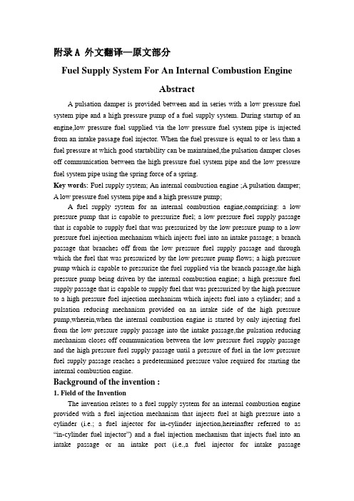
附录A 外文翻译—原文部分Fuel Supply System For An Internal Combustion EngineAbstractA pulsation damper is provided between and in series with a low pressure fuel system pipe and a high pressure pump of a fuel supply system. During startup of an engine,low pressure fuel supplied via the low pressure fuel system pipe is injected from an intake passage fuel injector. When the fuel pressure is equal to or less than a fuel pressure at which good startability can be maintained,the pulsation damper closes off communication between the high pressure fuel system pipe and the low pressure fuel system pipe using the spring force of a spring.Keywords: Fuel supply system; An internal combustion engine;A pulsation damper;A low pressure fuel system pipe and a high pressure pump;A fuel supply system for an internal combustion engine,comprising: a low pressure pump that is capable to pressurize fuel; a low pressure fuel supply passage that is capable to supply fuel that was pressurized by the low pressure pump to a low pressure fuel injection mechanism which injects fuel into an intake passage; a branch passage that branches off from the low pressure fuel supply passage and through which the fuel that was pressurized by the low pressure pump flows; a high pressure pump which is capable to pressurize the fuel supplied via the branch passage,the high pressure pump being driven by the internal combustion engine; a high pressure fuel supply passage that is capable to supply fuel that was pressurized by the high pressure to a high pressure fuel injection mechanism which injects fuel into a cylinder; and a pulsation reducing mechanism provided on an intake side of the high pressure pump,wherein,when the internal combustion engine is started by only injecting fuel from the low pressure supply passage into the intake passage,the pulsation reducing mechanism closes off communication between the low pressure fuel supply passage and the high pressure fuel supply passage until a pressure of fuel in the low pressure fuel supply passage reaches a predetermined pressure value required for starting the internal combustion engine.Background of the invention :1. Field of the InventionThe invention relates to a fuel supply system for an internal combustion engine provided with a fuel injection mechanism that injects fuel at high pressure into a cylinder (i.e.; a fuel injector for in-cylinder injection,hereinafter referred to as “in-cylinder fuel injector”) and a fuel injection mechanism that injects fuel into an intake passage or an intake port (i.e.,a fuel injector for intake passageinjection,hereinafter referred to as “intake passage fuel injector”). More particularly,the invention relates to a fuel supply system that can improve startability of an internal combustion engine.2. Description of the Related ArtA gasoline engine is known which is provided with a fast fuel injection valve for injecting fuel into a combustion chamber of the engine (i.e.,an in-cylinder fuel injector) and a second fuel injection valve for injecting fuel into an intake passage (i.e.,an intake passage fuel injector),and divides the injected fuel between the in-cylinder fuel injector and the intake passage fuel injector according to the engine speed and engine load. Also,a direct injection gasoline engine is also known which is provided with only a fuel injection valve for injecting fuel into the combustion chamber of the engine (i.e.,an in-cylinder fuel injector). In a high pressure fuel system that includes an in-cylinder fuel injector,fuel of which the pressure has been increased by a high pressure fuel pump is supplied to the in-cylinder fuel injector via a delivery pipe. The in-cylinder fuel injector then injects the high pressure fuel into the combustion chamber of each cylinder of the internal combustion engine.In addition,a diesel engine is also known which has a common rail type fuel injection system. In this common rail type fuel injection system,fuel which has been increased in pressure by a high pressure fuel pump is stored in a common rail. The high pressure fuel is then injected into the combustion chamber of each cylinder of the diesel engine from the common rail by opening and closing an electromagnetic valve.In order to increase the pressure of (i.e.,pressurize) the fuel in this kind of internal combustion engine,a high pressure fuel pump is provided which is driven by a cam provided on a driveshaft that is connected to a crankshaft of the internal combustion engine.Japanese Patent Application Publication No. JP-A-2005-139923 describes a high pressure fuel supply system for an internal combustion engine that can reduce vibrational noise when only a small amount of fuel is required by the internal combustion engine,such as during idling,while being able to deliver the necessary amount of fuel over the entire operating range of the internal combustion engine. This high pressure fuel supply system for an internal combustion engine has a two single plunger type high pressure fuel pumps each of which have a spill valve that spills fuel drawn into a pressurizing chamber that is divided by a cylinder and a plunger that moves back and forth in the cylinder,from that pressurizing chamber. When fuel is pressurized and delivered from the pressurizing chamber to the high pressure fuel system,the amount of fuel delivered is adjusted by controlling the spill valve open andclosed. One of these high pressure fuel pumps is a first high pressure fuel pump in which the lift amount of the plunger is small and the other high pressure fuel pump is a second high pressure fuel pump in which the lift amount of the plunger is large. In addition to these two high pressure fuel pumps,the high pressure fuel supply system for an internal combustion engine also includes control means. The control means controls the spill valve of each high pressure fuel pump according to the amount of fuel required by the internal combustion engine,such that fuel is pressurized and delivered using only the first high pressure fuel pump when the amount of required fuel is small,and fuel is pressurized and delivered using at least the second high pressure fuel pump when the amount of required fuel is large.According to this high pressure fuel supply system for an internal combustion engine,of the two high pressure fuel pumps,the first high pressure fuel pump has a plunger with a small lift amount so the rate of pressure increase is small and a large amount of water hammer is also self-suppressed. That is,with the high pressure fuel supply system,the vibrational noise produced when the required fuel quantity is small can be preferably reduced by controlling the spill valve of each of the high pressure fuel pumps so that only the first high pressure fuel pump is used when the amount of fuel required for the internal combustion engine is small such as during idling. On the other hand,the second high pressure fuel pump has a plunger with a large lift amount so pressurizing and delivering fuel using at least this second high pressure fuel pump also makes it possible to deliver the required fuel quantity when the amount of fuel required by the internal combustion engine increases to the point where it can no longer be delivered by the first high pressure fuel pump alone. That is,providing two high pressure fuel pumps having plungers with different lift amounts in this way enables the required amount of fuel to be delivered throughout the entire operating range of the internal combustion engine,while reducing vibrational noise when the amount of required fuel is small.In Japanese Patent Application Publication No. JP-A-2005-139923,the high pressure fuel supply system for a V-type 8 cylinder internal combustion engine having an in-cylinder fuel injector in each cylinder is provided with a high pressure fuel pump for each bank. Tip ends that branch off from a low pressure fuel passage which is connected to the fuel tank are connected to galleries of these high pressure fuel pumps. For each bank,a pulsation damper is provided midway between the branch portion of the low pressure fuel passage and the portion that connects with the gallery. This pulsation damper suppresses the pulsation in the fuel pressure in the low pressurefuel passage when the high pressure fuel pump is operating. At engine startup in this kind of a direct injection engine having only an in-cylinder fuel injector,fuel is unable to be delivered by the high pressure fuel pump until the engine turns over. Therefore,low pressure fuel is delivered by a feed pump to the fuel injection for in-cylinder injection. Therefore,the pulsation damper is designed to provide communication between the high pressure pipe system and the low pressure pipe system. For example,FIG. 6 is a sectional view of such a pulsation damper 215 ,FIG.7 is a sectional view taken along line VII-VII of FIG. 6 ,and FIG. 8 is a sectional view taken along line VIII-VIII of FIG. 7. As shown in FIGS. 6 to 8,grooves 223 A,223 B,223 C,and223 D are provided in an end face (i.e.,the upper surface in FIG. 8) that abuts against a contacting member 226 A of the pulsation damper 215 . Therefore,when the feed pressure is low,the spring 226 D presses the contacting member 226 A against the upper surface of the member that forms the inlet 222 and the outlet 224 . In this way,the structure is such that even if pressure is applied by the spring 226 D,the grooves 223 A,223 B,223 C,and223 D enable fuel delivered from the inlet 222 (i.e.,the feed pump side) to flow into the outlet 224 (i.e.,the high pressure fuel pump side) as shown by the dotted line in FIG. 8. On the other hand,as described above,an engine is known which includes,for each cylinder,an in-cylinder fuel injector that injects fuel into a combustion chamber of the engine and an intake passage fuel injector that injects fuel into an intake passage. In this engine,fuel is injected divided between the in-cylinder fuel injector and the intake passage fuel injector according to the engine speed and the load on the internal combustion engine. This engine is also providedwith the pulsation damper shown in FIGS. 6 to 8.However,in this kind of engine,the following problems occur when starting the engine by injecting fuel with an intake passage fuel injector. When fuel is delivered by a feed pump at engine startup,the volume of pipe that needs to be charged with fuel becomes significantly larger. That is,when the engine is started with fuel injected from the intake passage fuel injector,despite the fact that fuel can be delivered to the intake passage fuel injector with the feed pump by simply charging only the low pressure pipe with fuel,the pulsation damper is structured such that the high pressure pipe system and the low pressure pipe system are communicated or open to one another. Therefore,fuel is unable to be delivered to the intake passage fuel injector bythe feed pump unless both the low pressure pipe and the high pressure pipe are charged with fuel. As a result,it takes time for the feed pressure to rise,thereby adversely affecting startability (i.e.,increasing the start time).Summary of the inventionThis invention thus provides a fuel supply system for an internal combustion engine,which is capable of improving startability of an internal combustion engine that includes a fuel injection mechanism for injecting fuel at high pressure into a cylinder (i.e.,in-cylinder fuel injector) and a fuel injecting mechanism for injecting fuel into an intake passage or an intake port (i.e.,an intake passage fuel injector).A first aspect of the invention relates to a fuel supply system for an internal combustion engine which includes a low pressure fuel supply passage that supplies fuel that was pressurized by a low pressure pump to a low pressure fuel injection mechanism which injects fuel into an intake passage; a branch passage that branches off from the low pressure fuel supply passage and supplies fuel to a high pressure pump that is driven by the internal combustion engine; a high pressure fuel supply passage that supplies fuel that was pressurized by the high pressure pump to a high pressure fuel injection mechanism which injects fuel into a cylinder; and a pulsation reducing mechanism provided on the intake side of the high pressure pump. The pulsation reducing mechanism closes off communication between the low pressure fuel supply passage and the high pressure fuel supply passage when a pressure of fuel in the low pressure fuel supply passage is lower than a predetermined value.According to this first aspect,the high pressure pump which is driven by the internal combustion engine does not operate during startup of the internal combustion engine. In this case,the internal combustion engine is started by injecting fuel that has been pressurized by the low pressure pump from the low pressure fuel injection mechanism via the low pressure fuel supply passage. In this case,during startup of the internal combustion engine when the pressure of fuel in the low pressure fuel supply passage is low,the pulsation reducing mechanism closes off communication between the low pressure fuel supply passage and the high pressure fuel supply passage. Therefore,fuel can be delivered to the low pressure fuel injection mechanism simply by charging the low pressure fuel supply passage with fuel using the low pressure pump. Accordingly,there is no need to charge the high pressure fuel supply passage with fuel using the low pressure pump so the low pressure fuel supply passage and the branch passage that provides communication between the low pressure fuel supply passage and the high pressure pump can be charged with fuel quickly,and fuel can be quickly injected from the low pressure fuel injection mechanism. As a result,startability of an internal combustion engine provided with a fuel injectionmechanism that injects fuel at high pressure into the cylinder and a fuel injection mechanism that injects fuel into the intake passage or intake port can be improved.附录B 外文翻译—译文部分内燃机的燃油供应系统摘要在低压燃油供应系统管道和燃油供应系统的高压泵之间有一系列的有节奏的脉动衰减节气阀。
Lesson 8 Systems of Marine Diesel Engine

Lesson 8 Systems of Marine Diesel Engine船用柴油机系统Fuel oil systemThe fuel oil system for a diesel engine can be considered in two parts—the fuel supply and the fuel injection systems. 柴油机的燃油系统可分为燃油供应系统和燃油喷射系统两部分。
Fuel supply deals with the provision of fuel oil suitable for use by the injection system.燃油供应是指提供适合喷射系统使用的燃油。
A.Fuel oil supply for a two-stroke diesel engine二冲程柴油机的燃油供给A slow-speed two-stroke diesel is usually arranged to operate continuously on heavy fuel and have available a diesel oil supply for maneuvering conditions. 低速二冲程柴油机通常被设计为持续运行使用重油,同时,在机动操纵条件下也可使用柴油。
In the system shown in Fig. 8-1, the oil is stored in tanks in the double bottom from which it is pumped to a settling tank and heated. 在图8-1所示的系统中,燃油被储存在双层底舱中,从这里被泵泵送至沉淀柜并加热。
After passing through centrifuges then cleaned, heated oil is pumped to a daily service tank. 经过分油机离心分离后,干净的热油被泵送到日用油柜。
重型卡车供油系统-中英文版 2015-10
目录
Contents
低压燃油系统 Low Pressure Fuel System 燃油箱 Fuel tank
油量传感器 Fuel level sensor
燃油粗滤器 Fuel pre-filter
燃油管 Fuel pipe
油量传感器 Fuel level sensor
结构及功用
Structure and function
燃油箱 Fuel tank
维护及保养 maintenance
铝合金燃油箱在使用过程中,应注意以下事项: 1、禁止磕碰;
2、禁止踩踏;
3、整车行驶达到2000公里时必须对油箱拉带螺母进行首次复紧,复紧扭矩4 5±3 N*m,以后每行驶5000 公里进行一次复紧。
Aluminum alloy fuel tank in use process,the following items should be paid attention : 1. No knock; 2. No trample; 3. When the vehicle reaches 2000 km, must screw fuel tank strap nuts once more,The
目录
Contents
低压燃油系统 Low Pressure Fuel System 燃油箱 Fuel tank 油量传感器 Fuel level sensor 燃油滤清器 Fuel filter
燃油管 Fuel pipe
燃油箱 Fuel tank
功能与关键特性
Function & Key points
Sensor mounting holes
Cover
Partition
Expansion space
汽车专业英语第三章03-fuel system

• The fuel delivery system has the important role of delivering fuel to the injectors.
• The fuel must also be delivered in the right quantities and at the right pressure.
• Multiport fuel injection (MFI) systems 多端口燃油喷射系统
• Plastic 塑料 • Nylon 尼龙 • Rubber 橡胶 • hose, tube, pipe 软管,管子,管道 • tube bender [机] 弯管机 • grind打磨,磨 • weld 焊接 • sequential order相继次序,先后顺序 • asynchronous 异步的 • synchronous 、synchronized 同步的 • trigger vt.触发,引发,引起;
Changing(改变) brands(牌号) or grades(等 级) of gasoline may eliminate these problems.
汽车燃料是碳氢化合物。劣质汽油会引起起动困难、 迟缓、失速(停止)和爆震。改变汽油的品牌或等级可 以消除这些问题。
3.1.1 Octane Number
3.1 Automotive Fuels
Automotive fuels are hydrocarbon compounds. Poorquality(劣质) gasoline can cause hard(困难的) starting, hesitation(迟缓), stalling, and detonation (爆震).
The gasoline machine fuel supplies system解析

空气滤清器
空气滤清器是发动机非常重要的配套产品之一,它保护发动机,滤除空气中的 硬质灰尘颗粒,向发动机提供清洁空气,防止灰尘造成发动机磨损,对发动机 的可靠性和耐久性起关键作用。因此: 1.空气滤清器的结构和容量必须满足发动机的使用性能和工作条件。 2.空气滤清器的质量必须达到国家制定的检验标准。 3.与空气滤清器相连的管路及接口必须保证严格密封,不得漏气,并必须保证 可靠耐久。 4.空气滤清器进气管入口的位置,应设在尘土最少、不进雨或雪、温度低、无 热气及废气的部位,并具有相应措施。 5.空气滤清器必须定期保养及更换滤芯。 6.在尘土大的环境及地区中使用,必须选用加大容量的空气滤清器(或加强型 ),同时滤芯的更换周期应相应缩短。 上述各点均应得到重视,否则,将不同程度地导致发动机气缸的早期磨损,继 而使发动机窜气窜机油,动力下降。
(6)平衡油室的结构,平时在弹簧作用下,针阀将进油口关闭,当发动机工 作时,油室燃油被吸形成真空,大气压将平衡膜上压,通过杠杆将针阀门打开 ,使泵油室内的油进入平衡室。针阀开度随发动机负荷变化而变化,自动调节 。因此泵膜式化油器不受油面限制,在任何倾斜度下都能正常工作。
膜片式化油器结构及工作原理
空气滤清器最基本的技术参数是空气滤清器的空气流量,单位以每小时立方米 计(空气滤清器的 允用流量越大,则其外形尺寸及滤芯的过滤面积越大,相应容纳灰尘的容量也 越大。 空气滤清器的基本原则是:空气滤清器的额定空气流量必须大于发动机在额定 转速及额定功率下的空气流量,即发动机的最大进气量。同时,在安装空间允 许的前提下,适当采用大容量和大流量的空气滤清器是必要的,这有助于减小 空气滤清器的阻力,增大储尘能力和延长保养周期。 发动机在额定转速和额定负荷下的最大进气量与下列因素有关: *、发动机的排量 *、发动机的额定转速 *、发动机的吸气形式。
(9)柴油机燃料供给系统
• 不能正常点火(失火) • 注射、喷射 • 喷油器 • 喷油泵 • 失控下降、熄火 • 调速器 • 动力不足 • 排放不正常 • 突然失速 • 燃油开关
二、课文分析 • From the injection pump the fuel is fed through the high-pressure lines to the nozzles.
Text6 Diesel Engine Fuel System
一、词汇分析
• diesel
• primary
filter winding
• sencondary • supply点火线 圈)
• 次级的 • 输油泵
• misfiring mis+firing • injection • injector • injection pump • stalling • speed governor • lack of power • smoky exhaust • sudden stalling • fuel shut-off cock
课堂练习
• 1、喷油泵的翻译是(B ) • A、primary filter;B、injection pump; • C、water pump;D、fuel injector。 • 2、用英语说出你知道的滤清器_______ • ________________________________。 • 3、A diesel engine fuel system consists of a
• 燃油在喷油泵里加压,再经过高压油管送入 到喷油器。
汽车专业英语术语汇总(复习资料)

UNIT 1 AUTOMOTIVE BASICS Body:车身chassis:底盘stream-lined:流线wind resistance:风阻Frame:车架the power train:传动系统the drive train:驱动系a unitized body:承载式车身unibody:整体式汽车车身suspension system:悬架系统steering system:转向系统braking system(制动系统) suspension system:悬架系统shock absorber:减振器control arm:控制臂、导向机构steering gears:转向器steering wheel:转向盘idler arm:随动臂tie rods:横拉杆power steering:动力转向Power booster:助力器master cylinder:制动主缸Disc brake:盘式制动drum brake:鼓式制动Brake pedal:制动踏板brake system:制动系统stopping power:制动力Hydraulic brakes:液压制动brake pedal:制动踏板brake fluid:制动液brake lines:制动管路cylinders:轮缸brake shoes:制动蹄drum:制动鼓disc brake:盘式制动器pliers:老虎钳squeeze:挤进,握紧;夹紧rotating disc:旋转制动盘Drum brake:鼓式制动器gasoline-burning piston engine:活塞式汽油发动机Diesel-fuel burning engines:柴油发动机Fuel system:供给系统exhaust system:排气系统Cooling system:冷却系统lubrication system:润滑系统ignition system:点火系统electric spark:电火花air-fuel mixture:可燃混合气cylinder:汽缸ignition switch:点火开关current:电流storage battery:蓄电池ignition coil:点火线圈Distributor:分电器spark plug:火花塞compression ignition engines:压燃式发动机charging circuit:充电电路regulator:电压调节器alternator (or generator):发电机mechanical energy:机械能electrical energy:电能maximum voltage:最大电压fuel system:燃料供给系统fuel pump:燃油泵Filter:滤清器carburetor:化油器fuel injection system:燃油喷射系统combustible mixture:可燃混合气manifold:进气管exhaust system:排气系统carbon monoxide:一氧化碳hydrocarbons(碳氢化合物)oxides of nitrogen:氮氧化合物emission control system:排放控制系统cooling system:冷却系统combustion chamber:燃烧室coolant:冷却液Radiator:散热器water pump:水泵hollow:空的、空洞的block:汽缸体head:汽缸盖Defroster:(除冰(或霜)装置) Lubrication system润滑系统lubricant:润滑剂piston rings:活塞环cylinder walls:汽缸壁oil filter:机油滤清器Transmission:变速器wheel bearings:车轮轴承differential:差速器steering linkage:转向链接机构power train:传动系统transmission:变速器shift lever:变速杆clutch:离合器Transmission:变速器torque:转矩Differential:差速器drive /propeller shaft:传动轴universal joints:万向节axle movement:轴向运动flexible universal joints:活动万向节Differential:差速器UNIT 2 AUTOMOTIVE ENGINEinternal combustion engine:内燃机liquefied petroleum gas(LPG):液化石油气Compressed natural gas(CNG):压缩天然气drive shaft:驱动轴rear-wheel-drive arrangement:后轮驱动布置形式front-wheel-drive arrangement:前轮驱动布置形式drive wheels:驱动轮mid-engine arrangement:发动机中置Pistons:活塞reciprocate:往复spark ignition engine:火花点燃式发动机compression ignition(CI) engine:压燃式发动机electric ignition system:电子点火系统spark plug:火花塞ignite:点燃cylinders:气缸combustion:燃烧compression-ignition engine:压燃式发动机diesel engine:柴油机Spray:喷入heavy-duty trucks:重型货车spark-ignition engine:火花点燃式发动机fuel system:燃料供给系统ignition system:点火系统lubricating system:润滑系统cooling system:冷却系统fuel system:燃料供给系统combustible mixture:可燃混合物air/fuel mixture:空气燃料混合气ignition system:点火系统spark plug:火花塞air/fuel mixture:可燃混合气lubricating oil:润滑油lubricating system:润滑系统oil pump:机油泵reservoir:贮存器; 油箱exhaust gas:排气cooling system:冷却系统exhaust system:排气系统emission-control system:排放控制系统starting system:启动系统Crank:转动曲柄starting motor:启动马达internal combustion engine:内燃机chemical energy:化学能heat energy:热能mechanical energy:机械能air/fuel ratio:空燃比Diesel engines:柴油机intake:进气connecting rod:连杆crankshaft:曲轴reciprocating movement/back and forth movement/up and down movement(往复运动) rotary motion/ turning motion:(旋转运动) crankshaft:曲轴Efficiency:效率potential energy:潜能mechanical energy:机械能overall efficiency:总效率compression ratio:压缩比air/fuel ratio:空燃比uppermost position/(TDC, top dead center:上止点lowest position/BDC, bottom dead center:下止点stroke:行程four stroke-cycle Gasoline Engine: intake stroke:进气行程compression stroke:压缩行程power stroke:作功行程exhaust stroke:排气行程revolution:转、圈connecting rod:连杆intake valve:进气门camshaft:凸轮轴pressure difference:压力差air/fuel mixture:空气/燃料混合气compression ratio:压缩比TDC:上止点exhaust valve:排气门exhaust gases:废气starter motor:启动马达ignition key:点火钥匙start position:启动位置Flywheel:飞轮UNIT 3 AUTOMOTIVE LUBRICATION SYSTEM (汽车润滑系统) 3.1 Lubrication Principles 润滑原理Friction:摩擦primary job:基本任务Residual oil:残留的机油Lubricant:滑润剂hydrodynamic:液力的oil adhesion:机油粘度sliding friction:滑动摩擦Pressure-Lubrication System压力润滑系统oil pan:油底壳block:汽缸体oil pump:油泵drain plug:放油螺塞oil-pan gasket:油底壳垫圈Passageway:油道oil filter:机油滤清器Crankcase:曲轴箱tube:管filter screen:滤网gear-type:齿轮泵rotor-type:转子泵full-flow filtering system:全流式滤清器pressure-relief valve:安全阀bypass valve:旁通阀camshaft(凸轮轴)main bearing:主轴承camshaft bearing:凸轮轴轴承Foam inhibitor:泡沫抑制剂UNIT 4 THE COOLING SYSTEM(冷却系统) exhaust system:排气系统cylinder wall:汽缸壁piston:活塞cylinder head:汽缸盖oil film:油膜fuel mileage:燃油经济性exhaust emissions:废气排放liquid cooling:水冷air cooling:风冷water jacket:水套thermostat:节温器water pump:水泵radiator:散热器radiator cap:散热器盖cooling fan:冷却风扇hoses:软管expansion tank:膨胀水箱overflow tank:溢流水箱4.1 Water Pump(水泵)centrifugal pump:离心泵centrifugal force:离心力4.2 Water Jacket(水套)hot spot:热点valve seat:气门座valve guide:气门导管cylinder wall:汽缸壁combustion chamber:燃烧室4.3 Radiator(散热器)heat exchanger:热交换器4.4 Pressure Cap(散热器盖)boiling point:沸点pressure release valve:减压阀, 安全阀overflow tube:溢流管overflow tank:溢流箱4.5 Thermostat(节温器)4.6 Fancooling fan:冷却风扇constant temperature:常温thermostatic switch:温控开关UNIT 5 FUEL INJECTION SYSTEMFuel injection system:燃油喷射系统purely mechanical:纯机械的electronic fuel injection system:电子燃油喷射系统feedback control:反馈控制emission:排放solenoid valve:电磁阀injector:喷油器best power:最佳动力性best emission:最佳排放性best economy:最佳经济性rich condition:浓(混合气)工况lean condition:稀(混合气)工况5.3 Fuel System(燃油系统)fuel rail:油轨regulator:压力调节器return line:回油管fuel manifold:燃油歧管intake manifold:进气歧管5.4 Air Metering and Measurement 空气计量butterfly valve:传统碟形阀throttle body assembly:节气门体总成Mass Airflow:质量流量Speed Density:速度密度spring loaded flap:翼片potentiometer:电位计heated wire:加热电阻丝voltage signal:电压信号5.5 Most EFI systems measure the same basic 6 input 大多数EFI系统检测6个基本输入(信号)RPM(转速)ignition coil:点火线圈magnetic sensor:磁脉冲传感器Hall effect sensor:霍尔效应传感器Manifold Pressure (进气歧管压力)Throttle Position (节气门位置)Water Temperatureinjector pulse width:喷油器脉冲宽度Air Temperature5.6 Oxygen Sensor(氧传感器)closed loop systems:闭环系统oxygen content:氧含量air/fuel ratio:空燃比open loop mode:开环模式UNIT 6 EXHAUST SYSTEMexhaust system:排气系统Exhaust gas:废气combustion chamber:燃烧室muffler:消声器catalytic converter:催化转换器6.2 The Muffler(消声器)backpressure:背压exhaust valve:排气门6.3 The Exhaust Manifold and Headerexhaust manifold:排气歧管cylinder head:气缸盖intake manifold:进气歧管UNIT 7 THE IGNITION SYSTEM(点火系统) breaker point type ignition system:触点型点火系统electronic ignition system:电子点火系统distributorless ignition system: 无分电器点火系统)timing of the spark plug firing: 火花塞点火次序spark plug gap:火花塞间隙7.1 Point-Type Ignition System (触点型点火系统)electrical circuit:电路primary circuit:初级回路secondary circuit:次级回路breaker point:触点ignition switch:点火开关secondary winding:次级线圈high-tension lead:高压导线distributor:分电器coil:点火线圈distributor cap:分电器盖distributor rotor:分火头controlling element:控制元件primary current:初级电流Distributor:配电器7.2 Electronic Ignition Systems(电子点火系统)electronic control module:电子控制模块7.3 Distributorless Ignition Systems (DIS) (无分电器点火系统)spark timing:点火正时Ignition Control Unit (ICU):点火控制单元Engine Control Unit (ECU):发动机控制单元firing order:点火顺序Top Dead Center (TDC):上止点UNIT 8 CLUTCHdrive line/drive train:传动系统Clutch:离合器transmission:变速器drive shaft:传动轴final drive assembly:主减速器总成clutch disc:离合器片pressure plate:压盘pressure plate cover:离合器盖friction mechanism:摩擦机构engine torque:发动机扭矩gear ratio:传动比clutch pedal:离合器踏板driven member:从动件transmission input shaft:变速器输入轴driving members:主动件crankshaft:曲轴torsional shock:扭转振动starter motor:启动马达splined hub:花键毂spline:花键diaphragm spring:膜片弹簧centrifugal force:离心力release bearing:分离轴承disengagement mechanism:分离机构hydraulic system:液压系统hydraulic mechanism:液压机构clutch master cylinder:离合器主缸hydraulic fluid:制动液clutch release cylinder:离合器分离缸UNIT 9 AUTOMATIC TRANSMISSION(自动变速器)fluid coupling(液力偶合器)torque converter(变矩器rear wheel drive(后轮驱动)front wheel drive(前轮驱动).drive shaft(驱动轴)final drive(主减速器)rear axle(后轴)rear wheels(后轮)transaxle(驱动桥)Front axles(前桥)planetary gear sets(行星齿轮组) 9.1hydraulic system(液力系统)9.2Planetary gear sets(行星齿轮组)sun gear(太阳轮)ring gear(齿圈)planet gears(行星轮)constant mesh(常啮合common carrier(行星架)input shaft(输入轴)output shaft(输出轴)9.2 Clutch pack(离合器组)clutch drum(离合器鼓)friction material(摩擦材料)9.3 One-Way Clutch(单向离合器)"sprag" clutch(超越离合器)neutral(空挡)9.4 Bands(制动带)9.5 Torque Converter(液力变矩器)(见阅读材料)Torque Converter(液力变矩器)manual transmission:自动变速器automatic transmission:自动变速器brake pedal:制动踏板gas pedal:加速踏板1. Pump(泵轮).2. Turbine(涡轮).3. Stator(导轮).4. Transmission fluid(传动液). Freewheel:自由轮lockup clutch:锁止离合器UNIT 10 THE DIFFERENTIAL(差速器) unlimited-slip, differential:不防滑差速器10.1 The Main Gears(主减速器)bevel gear:锥齿轮axle shaft:半轴final drive assembly:主减速器总成gear reduction:减速drive wheel:驱动轮drive shaft:传动轴spiral bevel gear:螺旋锥齿轮center line(centerline):中心线10.2 The Differential System(差速系统) axle shaft:半轴side gear:半轴齿轮UNIT 11 BRAKE SYSTEM(制动系统) kinetic energy:惯性能量momentum:动量thermal energy (heat):热能master cylinder:主缸brake pedal:制动踏板mechanical pressure:机械压力hydraulic pressure:液体压力brake line:制动管brake hose:制动软管slave cylinder:轮缸Brake fluid:制动液Shoe:制动蹄pad:制动块drums:制动鼓rotor:制动盘disk brake:盘式制动器drum brakes:鼓式制动器caliper:制动嵌brake shoe:制动蹄friction lining:摩擦衬片friction surface:摩擦表面emergency brake:紧急制动Power brake booster:动力制动助力器master cylinder:制动主缸brake pedal:制动踏板hydraulic actuator:液压传动机构wheel speed sensor:车轮速度传感器UNIT 14 ABS AND TCS14.1 Braking System Fundamentals, master cylinder:主缸wheel cylinders:轮缸caliper pistons:制动钳活塞rolling energy:旋转能量14.2 Antilock Braking Systems(防抱死制动系统)retarding force:制动力percent slip滑移率braking effectiveness:制动效能wheel speed sensors (WSS):车轮速度传感器。
车辆工程内燃机燃油供应系统中英文对照外文翻译文献
中英文翻译Fuel Supply System For An Internal Combustion EngineAbstractA pulsation damper is provided between and in series with a low pressure fuel system pipe and a high pressure pump of a fuel supply system. During startup of an engine,low pressure fuel supplied via the low pressure fuel system pipe is injected from an intake passage fuel injector. When the fuel pressure is equal to or less than a fuel pressure at which good startability can be maintained,the pulsation damper closes off communication between the high pressure fuel system pipe and the low pressure fuel system pipe using the spring force of a spring.Key words: Fuel supply system; An internal combustion engine ;A pulsation damper;A low pressure fuel system pipe and a high pressure pump;A fuel supply system for an internal combustion engine,comprising: a low pressure pump that is capable to pressurize fuel; a low pressure fuel supply passage that is capable to supply fuel that was pressurized by the low pressure pump to a low pressure fuel injection mechanism which injects fuel into an intake passage; a branch passage that branches off from the low pressure fuel supply passage and through which the fuel that was pressurized by the low pressure pump flows; a high pressure pump which is capable to pressurize the fuel supplied via the branch passage,the high pressure pump being driven by the internal combustion engine; a high pressure fuel supply passage that is capable to supply fuel that was pressurized by the high pressure to a high pressure fuel injection mechanism which injects fuel into a cylinder; and a pulsation reducing mechanism provided on an intake side of the high pressure pump,wherein,when the internal combustion engine is started by only injecting fuelfrom the low pressure supply passage into the intake passage,the pulsation reducing mechanism closes off communication between the low pressure fuel supply passage and the high pressure fuel supply passage until a pressure of fuel in the low pressure fuel supply passage reaches a predetermined pressure value required for starting the internal combustion engine.Background of the invention :1. Field of the InventionThe invention relates to a fuel supply system for an internal combustion engine provided with a fuel injection mechanism that injects fuel at high pressure into a cylinder (i.e.; a fuel injector for in-cylinder injection,hereinafter referred to as “in-cylinder fuel injector”) and a fuel injection mechanism that injects fuel into an intake passage or an intake port (i.e.,a fuel injector for intake passage injection,hereinafter referred to as “intake passage fuel injector”). More particularly,the invention relates to a fuel supply system that can improve startability of an internal combustion engine.2. Description of the Related ArtA gasoline engine is known which is provided with a fast fuel injection valve for injecting fuel into a combustion chamber of the engine (i.e.,an in-cylinder fuel injector) and a second fuel injection valve for injecting fuel into an intake passage (i.e.,an intake passage fuel injector),and divides the injected fuel between the in-cylinder fuel injector and the intake passage fuel injector according to the engine speed and engine load. Also,a direct injection gasoline engine is also known which is provided with only a fuel injection valve for injecting fuel into the combustion chamber of the engine (i.e.,an in-cylinder fuel injector). In a high pressure fuel system that includes an in-cylinder fuel injector,fuel of which the pressure has been increased by a high pressure fuel pump is supplied to the in-cylinder fuel injector via a delivery pipe. The in-cylinder fuel injector then injects the high pressure fuel into the combustion chamber of each cylinder of the internal combustion engine.In addition,a diesel engine is also known which has a common rail type fuel injection system. In this common rail type fuel injection system,fuel which has been increased in pressure by a high pressure fuel pump is stored in a common rail. The high pressure fuel is then injected into the combustion chamber of each cylinder of the diesel engine from the common rail by opening and closing an electromagnetic valve.In order to increase the pressure of (i.e.,pressurize) the fuel in this kind ofinternal combustion engine,a high pressure fuel pump is provided which is driven by a cam provided on a driveshaft that is connected to a crankshaft of the internal combustion engine.Japanese Patent Application Publication No. JP-A-2005-139923 describes a high pressure fuel supply system for an internal combustion engine that can reduce vibrational noise when only a small amount of fuel is required by the internal combustion engine,such as during idling,while being able to deliver the necessary amount of fuel over the entire operating range of the internal combustion engine. This high pressure fuel supply system for an internal combustion engine has a two single plunger type high pressure fuel pumps each of which have a spill valve that spills fuel drawn into a pressurizing chamber that is divided by a cylinder and a plunger that moves back and forth in the cylinder,from that pressurizing chamber. When fuel is pressurized and delivered from the pressurizing chamber to the high pressure fuel system,the amount of fuel delivered is adjusted by controlling the spill valve open and closed. One of these high pressure fuel pumps is a first high pressure fuel pump in which the lift amount of the plunger is small and the other high pressure fuel pump is a second high pressure fuel pump in which the lift amount of the plunger is large. In addition to these two high pressure fuel pumps,the high pressure fuel supply system for an internal combustion engine also includes control means. The control means controls the spill valve of each high pressure fuel pump according to the amount of fuel required by the internal combustion engine,such that fuel is pressurized and delivered using only the first high pressure fuel pump when the amount of required fuel is small,and fuel is pressurized and delivered using at least the second high pressure fuel pump when the amount of required fuel is large.According to this high pressure fuel supply system for an internal combustion engine,of the two high pressure fuel pumps,the first high pressure fuel pump has a plunger with a small lift amount so the rate of pressure increase is small and a large amount of water hammer is also self-suppressed. That is,with the high pressure fuel supply system,the vibrational noise produced when the required fuel quantity is small can be preferably reduced by controlling the spill valve of each of the high pressure fuel pumps so that only the first high pressure fuel pump is used when the amount of fuel required for the internal combustion engine is small such as during idling. On the other hand,the second high pressure fuel pump has a plunger with a large lift amount so pressurizing and delivering fuel using at least this second high pressure fuel pumpalso makes it possible to deliver the required fuel quantity when the amount of fuel required by the internal combustion engine increases to the point where it can no longer be delivered by the first high pressure fuel pump alone. That is,providing two high pressure fuel pumps having plungers with different lift amounts in this way enables the required amount of fuel to be delivered throughout the entire operating range of the internal combustion engine,while reducing vibrational noise when the amount of required fuel is small.In Japanese Patent Application Publication No. JP-A-2005-139923,the high pressure fuel supply system for a V-type 8 cylinder internal combustion engine having an in-cylinder fuel injector in each cylinder is provided with a high pressure fuel pump for each bank. Tip ends that branch off from a low pressure fuel passage which is connected to the fuel tank are connected to galleries of these high pressure fuel pumps. For each bank,a pulsation damper is provided midway between the branch portion of the low pressure fuel passage and the portion that connects with the gallery. This pulsation damper suppresses the pulsation in the fuel pressure in the low pressure fuel passage when the high pressure fuel pump is operating. At engine startup in this kind of a direct injection engine having only an in-cylinder fuel injector,fuel is unable to be delivered by the high pressure fuel pump until the engine turns over. Therefore,low pressure fuel is delivered by a feed pump to the fuel injection for in-cylinder injection. Therefore,the pulsation damper is designed to provide communication between the high pressure pipe system and the low pressure pipe system. For example,FIG. 6 is a sectional view of such a pulsation damper 215 ,FIG.7 is a sectional view taken along line VII-VII of FIG. 6 ,and FIG. 8 is a sectional view taken along line VIII-VIII of FIG. 7. As shown in FIGS. 6 to 8,grooves 223 A,223 B,223 C,and 223 D are provided in an end face (i.e.,the upper surface in FIG. 8) that abuts against a contacting member 226 A of the pulsation damper 215 . Therefore,when the feed pressure is low,the spring 226 D presses the contacting member 226 A against the upper surface of the member that forms the inlet 222 and the outlet 224 . In this way,the structure is such that even if pressure is applied by the spring 226 D,the grooves 223 A,223 B,223 C,and 223 D enable fuel delivered from the inlet 222 (i.e.,the feed pump side) to flow into the outlet 224 (i.e.,the high pressure fuel pump side) as shown by the dotted line in FIG. 8. On the other hand,as described above,an engine is known which includes,for each cylinder,an in-cylinder fuel injector that injects fuel into a combustion chamber of the engine and an intakepassage fuel injector that injects fuel into an intake passage. In this engine,fuel is injected divided between the in-cylinder fuel injector and the intake passage fuel injector according to the engine speed and the load on the internal combustion engine. This engine is also provided with the pulsation damper shown in FIGS. 6 to 8.However,in this kind of engine,the following problems occur when starting the engine by injecting fuel with an intake passage fuel injector. When fuel is delivered by a feed pump at engine startup,the volume of pipe that needs to be charged with fuel becomes significantly larger. That is,when the engine is started with fuel injected from the intake passage fuel injector,despite the fact that fuel can be delivered to the intake passage fuel injector with the feed pump by simply charging only the lowpressure pipe with fuel,the pulsation damper is structured such that the high pressure pipe system and the low pressure pipe system are communicated or open to one another. Therefore,fuel is unable to be delivered to the intake passage fuel injector by the feed pump unless both the low pressure pipe and the high pressure pipe are charged with fuel. As a result,it takes time for the feed pressure to rise,thereby adversely affecting startability (i.e.,increasing the start time).Summary of the inventionThis invention thus provides a fuel supply system for an internal combustion engine,which is capable of improving startability of an internal combustion engine that includes a fuel injection mechanism for injecting fuel at high pressure into a cylinder (i.e.,in-cylinder fuel injector) and a fuel injecting mechanism for injecting fuel into an intake passage or an intake port (i.e.,an intake passage fuel injector).A first aspect of the invention relates to a fuel supply system for an internal combustion engine which includes a low pressure fuel supply passage that supplies fuel that was pressurized by a low pressure pump to a low pressure fuel injection mechanism which injects fuel into an intake passage; a branch passage that branches off from the low pressure fuel supply passage and supplies fuel to a high pressure pump that is driven by the internal combustion engine; a high pressure fuel supply passage that supplies fuel that was pressurized by the high pressure pump to a high pressure fuel injection mechanism which injects fuel into a cylinder; and a pulsation reducing mechanism provided on the intake side of the high pressure pump. The pulsation reducing mechanism closes off communication between the low pressure fuel supply passage and the high pressure fuel supply passage when a pressure of fuel in the low pressure fuel supply passage is lower than a predetermined value.According to this first aspect,the high pressure pump which is driven by the internal combustion engine does not operate during startup of the internal combustion engine. In this case,the internal combustion engine is started by injecting fuel that has been pressurized by the low pressure pump from the low pressure fuel injection mechanism via the low pressure fuel supply passage. In this case,during startup of the internal combustion engine when the pressure of fuel in the low pressure fuel supply passage is low,the pulsation reducing mechanism closes off communication between the low pressure fuel supply passage and the high pressure fuel supply passage. Therefore,fuel can be delivered to the low pressure fuel injection mechanism simply by charging the low pressure fuel supply passage with fuel using the low pressurepump. Accordingly,there is no need to charge the high pressure fuel supply passage with fuel using the low pressure pump so the low pressure fuel supply passage and the branch passage that provides communication between the low pressure fuel supply passage and the high pressure pump can be charged with fuel quickly,and fuel can be quickly injected from the low pressure fuel injection mechanism. As a result,startability of an internal combustion engine provided with a fuel injection mechanism that injects fuel at high pressure into the cylinder and a fuel injection mechanism that injects fuel into the intake passage or intake port can be improved.内燃机的燃油供应系统摘要在低压燃油供应系统管道和燃油供应系统的高压泵之间有一系列的有节奏的脉动衰减节气阀。
汽车构造 上册6.化油器燃油供给系(双语)
燃料供给方式 supply methods
化油器方式 carburetion
汽油喷射方式 injection
二、化油器式汽油机燃料供给系的组成 Composition of gasoline engine fuel system with carburetor
① 燃油供给装置:汽油油箱 、汽油泵、汽油滤清器、 油管 Fuel supply devices: fuel tank, pump, fuel filter, fuel pipe. ② 空气供给装置:空气滤清器 Air supply device: air cleaner ③ 可燃混合气形成装置:化油器 Device forming combustible mixture: carburetor ④ 废气排出装置:排气管道、排气消音器,三元催化转 换器 Exhaust emission device: exhaust pipe , exhaust silencer, three-way catalyst converter
1、物理特性 physical properties: 粘度小、流动性好、自润性差。 2、使用性能指标 performance index/parameters: ⑴蒸发性evaporation:能被蒸发的性能。 ⑵热值thermal value:1kg燃料完全燃烧后所产生的 热量。(某些燃料的热值:液化气109.2MJ/m3或47.3MJ/kg;汽油46MJ/kg;煤油
1.2 1.0 0.8 0.6 0 20 小负荷 怠速 idling (节气门开度最小) 0.4 40 60 中负荷 80 2 1 3
Pe%
大负荷 全负荷 Full load (节气门开度最大)
Max. opening
电控燃油喷射系统工作原理

电控燃油喷射系统工作原理
电控燃油喷射系统(Electronic Fuel Injection System,简称EFI 系统)是一种利用计算机控制引擎燃油喷射量和喷射时机的燃油供给系统。
它的工作原理主要包括以下几个步骤:
1. 燃油供给:燃油经过燃油泵送压力后进入燃油喷射嘴,喷射嘴是由喷油电磁阀控制的。
燃油供给系统还包括燃油滤清器、燃油沉淀器等组件。
2. 空气供给:空气通过空气滤清器进入进气歧管,然后经过节气门进入发动机气缸。
3. 传感器控制:系统中配备了多个传感器,如空气流量传感器、氧气传感器、水温传感器等,用于监测发动机状态和环境参数。
这些传感器将收集的数据发送给控制器进行分析和计算。
4. 控制器计算:控制器是EFI系统中的核心部件,它根据传感器采集到的数据,通过内部的计算算法和存储的映射表,来确定当前的喷油量和喷油时机。
5. 喷油:根据控制器的指令,喷油器打开喷油电磁阀,让精确计算的燃油以适当的喷射时间和喷射量喷入发动机气缸中。
喷油时机和喷射量的精确控制能够提高燃烧效率,减少废气排放。
6. 点火系统:与EFI系统配套使用的还有点火系统,它控制着火花塞的点火时机和点火能量,以确保燃烧正常进行。
通过以上步骤,EFI系统可以实现对引擎燃油喷射量和喷射时机的精确控制,提高燃烧效率,降低废气排放,以及提升发动机的动力性能和燃油经济性。
汽油机燃料供给系(Gasoline engine fuel supply system)
汽油机燃料供给系(Gasoline engine fuel supply system)The fourth chapter gasoline engine fuel supply systemFirst, the multiple-choice question:The amount of fuel supplied by the 1. diaphragm type gasoline pump depends on the size of the pump.A. patch uplinkB. patch downlinkC. diaphragm spring tensionD. rocker swing momentum2. if the eccentric on the camshaft is badly worn, the gasoline pump ().A. fuel pressure riseB. lower fuel pressureC. increase of oil per cycleD. the fuel supply per cycle decreases3. when the gasoline engine is in the middle load condition, the excess air value should be ()A. 0.2, ~0.6B. 0.7~0.9C. 0.8, ~0.9D. 0.9~1.14., if the gasoline pump diaphragm spring is perfect, will make ().A. fuel supply increasedB. fuel supply decreasedC. fuel pressure is too highD. low fuel pressure5. now, the idle speed rating of the gasoline engine is higher than in the past.A. can increase the rated speed of engine and increase power accordinglyB. reduces fuel consumptionThe C. speeds up the engineD. can make use of lower mixture at idle and reduce exhaust pollution6. when the engine is under heavy load condition, the excess air coefficient should be in () range.A. 0.6 ~ 0.8B. 0.8 ~ 0.9C. 0.9 ~ 1.1D. 1.1 ~ 1.2When the 7. gasoline engine works, the inlet pipe enters the cylinderA. gasolineB. airC. gas mixtureD. diesel8. the main components of the gas mixture are: ()A. air filterB. carburetorC. gasoline pumpD. gasoline filter9. the main assemblies used to complete the delivery of gasoline during the operation of the gasoline engine are: ()A. air filterB. carburetorC. gasoline pumpD. gasoline filter10. the main assemblies used to provide clean air during the operation of the gasoline engine are: ()A. air filterB. carburetor;C. gasoline pump;D. gasoline filter11. the excess air factor of the theoretical mixture is: ()A. 1B. 0.85 ~ 0.95C. 1.05 ~ 1.15Fourteen point sevenThe excess air factor of the 12. power mixture is: ()A. 1B. 0.85 ~ 0.95C. 1.05 ~ 1.15D. 14.713. the excess air factor of the mixed gas is: ()A. 1B. 0.85 ~ 0.95C. 1.05 ~ 1.15D. 14.714. the air-fuel ratio of the theoretical mixture is: ()A. 1B. 0.85 ~ 0.95C. 1.05 ~ 1.15D. 14.715. what extent does the excess air coefficient of the mixture lead to when the combustion rate slows down and the performance of the engine begins to decrease? ()A. < 0.4 to 0.5;B. > 1.15;C. < 0.88;D. > 1.3 to 1.4Two 、 judgment questions:1. the gasoline engine mixture is formed in the cylinder. ()2. when the gasoline engine is working, the mixture is compressed and spontaneous combustion. ()3. the throttle valve in the carburetor is used to control the intake of the engine. ()4. when the gasoline engine burns normally, the flame should travel at a certain speed. ()5. the function of the venturi in the carburetor is to limit the intake. ()6. at idle, the throttle valve opens with minimal entry into the cylinder and requires a small amount of concentrated mixture. ()7. when the small load, the quantity and quality of the mixture is higher than the idle speed, so the mixture is required to be stronger than the idle speed. ()8. engines often work under moderate loads and should be supplied with a stronger mixture to ensure a good engine performance. ()9., in order to ensure the engine under large load dynamic requirements, should be supplied with a high concentration of power mixture. ()10. in idle conditions, the engine does not output power, the supply of a thinner mixture can meet the requirements. ()11. when the engine is speeding up, it should be added with a strong mixture to increase engine power rapidly. ()12. the air valve on the lid of the gasoline tank prevents the pressure in the tank from too low and affects the normal suction of the gasoline pump. ()The steam valve on the top of the 13. gasoline tank prevents the pressure in the tank from being too high, so as to ensure safety. ()14. in use, the gasoline filter can be installed in anydirection. ()15. the function of the gasoline pump is to filter the moisture and impurities in the gasoline. ()16. when the engine works, the fuel supply of the gasoline pump remains constant. ()17. with the hand rocker pump oil, if the float chamber oil level up to the required height, will not pull the rocker arm. ()18. when the engine works, no matter how much gasoline pump supplies, the rocker arm and diaphragm stroke are fixed. ()19. when the engine works, no matter how much fuel the pump supplies, the swing range of the rocker arm is fixed. ()20. gasoline pump is generally installed on the cylinder side, the use of eccentric wheel on the camshaft to drive. ()21. use air filters to filter out impurities in the air, mainly to reduce engine wear. ()22. air filter can only eliminate the impurity particles in the air of. ()23. paper dry air filter mainly filter the impurities in the air by its filter core. ()24. the paper dry air filter mainly uses the inertia way to filter out the impurity in the air. ()25. when maintaining, the filter core of paper dry air filter should be soaked in oil, and then installed again. ()26. in the whole range of the automobile engine, the main oil supply device acts as an oil supply. ()27. the main oil supply device uses the method of reducing the vacuum at the main orifice to ensure that the mixture becomes thinner as the opening of the valve increases. ()28., the idle device is to ensure that the engine in idle and very small load conditions, the supply of less dense mixture. ()29. when the engine is idle the idle jet and transition nozzle of the idle device are both injected with oil. ()30. whether the mechanical enrichment device works depends on the engine speed and load. ()31. whether the vacuum concentration device works depends only on the engine speed. ()32., the throttle valve opening increases, the acceleration device will work. ()33. when the engine starts cold, the choke valve is closed, mainly by reducing the amount of air supplied to increase the concentration of the mixture. ()34. the main purpose of the carburetor with multi venturi is to make the fuel atomization better. ()35. carburetor throttle valve is mainly used to control the amount of air intake, usually by the driver through the foot pedal control. ()36. the function of the intake manifold is to collect the exhaust gases from the cylinders and to exhaust them into the atmosphere. ()37. the function of the exhaust manifold is to collect the exhaust gases from the cylinders and to exhaust them into the atmosphere by the exhaust muffler. ()38. due to the installation of exhaust muffler to increase the exhaust resistance, engine power decreased slightly. ()Three. Questions and answers:What is the function of the fuel supply system of the 4-1. gasoline engine?What are the carburetor fuel supply systems for the 4-2. gasoline engine?What is the composition and function of the 4-3. float mechanism?4-4. what is the function of the metering hole in the simple carburetor?How does the 4-5. mixture form?4-6: gasoline engine combustion process is how to carry out?4-7. what is excess air factor?4-8. what is the air-fuel ratio?What is the effect of 4-9. mixture concentration on engine performance?4-10: what is the engine working condition? How to express?4-11: what is the engine load? How to express?4-12: when the engine works, what's the requirement for the gas mixture concentration?4-13: what valves are there on the lid of the gasoline tank? What is its function?What is the function of the 4-14. gasoline filter? How many kinds are there?What is the function of the 4-15. gasoline pump?Why is there a vent in the lower part of the 4-16. gasoline pump?How does the 4-17. gasoline pump adjust the fuel supply automatically?What's the function of the 4-18. air filter?What types of air filters are used in 4-19. at present? How does it filter out impurities in the air?What are the advantages and disadvantages of the 4-20. paper dry air filter?What is the function of the main oil supply device of the 4-21. carburetor? How to achieve its function in structure?What is the function of the 4-22. idle device? How does it work?What is the function of the 4-23. enrichment unit? Why are there two sets of condenser installed on the carburetor?What is the function of the 4-24. acceleration device?What is the function of the 4-25. starter? What is the usual starting device?What types of 4-26. carburetor do you have?What are the main control mechanisms for the 4-27. carburetor? What is its function?What is the function of the 4-28. intake and exhaust manifold?What is the function of the 4-29. exhaust muffler?How does the 4-30. check and adjust the height of the oil level in the float chamber?How does the 4-31. check and adjust engine idle speed?How does the 4-32. adjust the carburetor vacuum enrichment device?How does the 4-33. adjust the carburetor mechanical enrichment device?How does the 4-34. overhaul the carburetor accelerator pump?How does the 4-35. check the pump capacity of the gasoline pump?。
- 1、下载文档前请自行甄别文档内容的完整性,平台不提供额外的编辑、内容补充、找答案等附加服务。
- 2、"仅部分预览"的文档,不可在线预览部分如存在完整性等问题,可反馈申请退款(可完整预览的文档不适用该条件!)。
- 3、如文档侵犯您的权益,请联系客服反馈,我们会尽快为您处理(人工客服工作时间:9:00-18:30)。
Supply Of Oil FuelsAccurate and complete analyses are difficult to obtain but specifications should confirm that certain parameters are not exceeded. Samples of the oil delivered should be kept for reference.Density of the oil must be given (usually measured at 15°C), since the consignment will be measured by weight. It will also be necessary to know this to adjust centrifuges to give purification.Viscosity is required, to calculate temperatures at which the fuel is treated and injected into the engine.Flash point for the fuel must not be below 60°C, although the actual value need not be stated. This minimum is for safety reasons.All residual fuels will contain contaminants, and to protect the engine some of these must be removed or reduced. Solid contaminants may consist of rust, sand, dust and refinery catalysts (catalytic fines), all of which are abrasives and will cause wear in fuel pumps, injectors, cylinder, liners, piston rings and exhaust valve seats. Liquid contaminants will be salt or fresh water, which may also contain other soluble substances; all of these are corrosive.Fuel to be used is first transferred from storage tanks to a settling tank in which it is heated to allow some water and sludge to settle out by gravity and be drained off. The fuel is then passed through the purification system and discharged to a daily tank.There are usually two daily tanks, used alternately, one in use while the other is being recharged. Settling and service tanks are lagged to conserve heat.A recommended standard of treatment for residual fuel to be used in a large engine requires two centrifuges of adequate capacity, operating in series. The first acts as a purifier to remove water, solubles, sludge etc while the second acts as a clarifier to remove solids. The purifier must be fitted with the correct disc or dam to match the oil density. The oil is heated before purification (max temp 98°C) and the rate of throughput is limited to assist efficientseparation. Both centrifuges must be cleaned frequently. Such systems can operate effectively on oils densities up to 0.99.From the service tank the treated oil is pumped through a pressurised fuel system to the engine. With the oil temperatures necessary for high viscosity fuel, and the possibility that a trace of water may still be present, it is necessary to maintain the engine pump suctions and circulating connections under pressure to inhibit boiling, gasification and cavitation.The oil first passes to the primary or supply pump which raises its pressure to about 4 bar; this pressure is maintained in the circulating returns. The circulating or booster pump draws oil from the primary discharge, raising its pressure to 10/12 bar and delivering it through the heater, viscosity regulator and fine filter to the main engine fuel pumps. The heater reduces the oil’s viscosity for efficient combustion. The temperature required will depend upon the oil quality, but to avoid fouling it should not exceed 150°C. The fine filter is of stainless steel mesh to filter out particles larger than 50 microns (0.05mm), or less for smaller engines. Filters must be changed over and cleaned regularly.In large two-stroke engines the fuel injectors will circulate fuel during the periods they are not actually injecting it to the cylinder. This ensures the system remains fully primed and at uniform temperature. The circulated oil is returned to a buffer or venting tank from which it passes either back to the low pressure part of the system before the circulating pump suction, or into the service tank. The fuel oil system is shown below.All pumps are in duplicate and have safe pressure relief valves fitted. All pipes carrying hot oil must be well lagged and fitted with trace heating if necessary. Fuel pipes must be clipped and supported to reduce stress from vibration.A tank containing diesel oil may be connected to the main heavy fuel system. This will allow flushing with light oil before stopping the engine for long periods of for maintenance.Various safety devices must be included in the system with alarms to detect loss in oil pressure, low tank level etc. Quick closing valves which can be operated from outside the machinery space must be fitted to all tanks and to the main engines. Fuel pumps must have remote switches by which they can be stopped in a emergency.There must be arrangements for venting and draining the system, cleaning strainers etc, but utmost care must be taken. Drain trays and save-alls, where fitted, must be kept clean; all joints must be kept tight with safeguards to prevent the possibility of hot oil spraying on to heated surfaces.Oil contained in tank with open drains should not normally exceed a temperature of 50°C or, if this is lower, may not exceed a temperature 20°C below the flash point of the oil.The ViscothermWhen burning heavy fuel oil in a diesel engine it is necessary to reduce the high viscosity of the fuel to a value at which correct atomisation can take place in the fuel injectors. This will allow intimate mixing of the fuel oil with heated air for ignition and efficient combustion. Viscosity of a fuel may be reduced by raising the temperature and it is passed through a heater to do this. Automatic control of the heater may be regulated either to maintain a constant temperature, or to measure and control the viscosity.It is possible that oils of varying properties are contained within a ship’s bunker tanks or even one tank, when its contents are from a number of different sources. Consequently, it is preferable that the actual viscosity of the fuel is controlled within those limits. In most casts this is regulated to have kinematic between 10 and 15 centistokes at 50°C (that is 50-70 seconds Redwood No. 1, at 100°F).The Viscotherm shown is an instrument which measures fuel oil viscosity at the heater discharge and regulates the heater temperature to control this. It consists of a small gear type pump rotated at a slow but constant speed (40 rpm) and is fitted within the fuel supply close to the heater discharge. The pump draws fuel from the system at a controlled rate and discharges it through a capillary tube. The form of flow within a capillary tube at corresponding speeds is such that the pressure difference between each end of the tube is directly proportional to the viscosity of the oil flowing through it.Pressures at the corresponding points are measured with Bourdon tubes and compared to read as viscosity. In addition these pressures are fed to a differential pressure transmitter which can automatically operate the heater control to maintain fuel viscosity within close limits.All parts of the instrument are of stainless steel. In the event of a failure of this control an oil bypass valve is included in the system and the temperature may then be controlled by hand or by a thermostat.Combustion of FuelThe general indications of good combustion are similar in any operating diesel engine; a clear exhaust, power produced and with balanced exhaust temperatures normal for the throttle setting. There should be no uneven running, knocking from cylinders or the fuel system.Viscosity, or resistance to flow, in a fuel oil is important when considering combustion. It must be low enough to ensure correct atomisation at the fuel injector. Since viscosity reduces as temperature is increased, it will be necessary to heat heavy fuel oil to reduce its viscosity to about 15 cSt at 50°C before atomisation for combustion.Atomisation is the splitting up of the fuel into very small droplets by the fuel injector forcing fuel at high pressure through small atomiser holes. The droplet size will depend upon the size of holes and the pressure difference between fuel pump discharge and that of the compressed air in the combustion chamber, and consequently the size of droplets may vary over the whole injection period. Atomised droplets have a high surface to mass ratio giving good heat transfer from the hot compressed air in the cylinder causing rapid evaporation andmixing.Penetration refers to the distance the oil droplets travel into the combustion space before mixing with the air and igniting. This will depend upon the droplet size (atomisation), velocity leaving the injector and the conditions within the combustion chamber. It is desirable that fuel should penetrate into the whole of the combustion space for good mixing, but droplets should not impinge on the internal surfaces before burning. The number of atomiser holes and their position will decide the spray pattern.Turbulence is the movement of compressed air and fuel within the combustion space before combustion occurs. This may have several causes. Swirl is imparted to the air during its entry at scavenge ports. It may be further agitated by the fuel spray pattern and the shape and movement of the piston crown. Turbulence will improve the mixing of fuel and air for effective and rapid combustion. It is particularly desirable for rapid combustion of heavy fuels in medium or higher speed engines.Compression Ignition is the term used to describe the combustion in diesel engines and they are often referred to as compression ignition engines. The combustion process may be considered as three consecutive phases. In phase one the atomised oil droplets emitted from the fuel valve nozzle into the combustion space at the start of injection will evaporate and mix with hot, compressed air and some chemical changes will also occur. The mixture will reach an ignitable condition and spontaneous combustion will commence. The time elapsed during this phase it termed the ignition delay or ignition lag.In phase two the ignition and start of combustion will set up a flame front which will accelerate through the chamber, enveloping and burning all the other droplets present, causing a very rapid generation of heat with a corresponding rise in pressure and temperature.During the ignition delay, the injector continued to inject fuel and, if this has built up a sufficient quantity, the rapid combustion and pressure rise will be quite violent, causing detonation, the shock loading creating a noise termed diesel knock.Following the rapid pressure rise in phase two, hot, turbulent conditions existing in the combustion chamber will ignite and burn the remainder of the measured fuel charge as it is injected. This is phase three; it is termed the controlled part of the combustion process as pressure is regulated by the rate at which fuel continues to be delivered. The cylinder pressure may start to reduce as the piston moves down after passing over top centre.Ignition quality of a fuel is the term used to denote the ignition delay, combustion characteristics and tendency to cause knock. It depends mainly upon the form of the hydrocarbon compounds in the fuel and no precise unit has been derived to measure this.The most usual measure of ignition quality of distillate fuels is the Cetane number. This is found by comparison of the ‘knock producing’ properties to those of mixtures containing an equivalent percentage of Cetane when burnt in a test engine. A high Centane number indicates a short ignition delay. Cetane numbers are not quoted in normal fuel specifications or analyses. Slow speed, two-stroke engines can operate efficiently of fuels down to Cetane number of about 24 but medium speed, four-stroke engines normally require a figure above 34; high speed engines need higher figures. Another measure which is similar to Cetane number but found from different parameters of the fuel, is termed its diesel index.For residual or blended fuels the ignition can be expressed as a CCAI value (calculated carbon aromacity index) or CII (calculated ignition index). The lower the CCAI value, the better the ignition quality. A limiting figure of 870 is suggested. These units take the viscosity into consideration.The ignition quality of a fuel is particularly important for each of starting an engine, or when operating at reduced power for long periods. It can be improved by increasing the compression ratio of the engine or by pre-heating the scavenge air. There will be design or operational limits to both of these.Variable Ignition Timing (VIT). If an engine operates for long periods at reduced power or speed, the residual heat in the main components of the combustion chamber will decrease, causing a lower air temperature after combustion. This will lead to an increase in the ignition delay of injected fuel, which will cause knocking or ‘rough running’ in the engine, with consequent damage from shock loads and poor combustion. This problem can be reduced by the use of variable ignition timing to advance the start of injection, allowing for the longer delay but maintaining ignition timing and the same peak pressure. In large, two-stroke engines, variable ignition timing is automatically superimposed on the normal fuel pump setting from the engine governor. Additional linkage from the governor will advance each pump setting over the range of lower speeds. Fuel pumps are designed to carry out necessary adjustment while the engine is running. This control can also be manually regulated to advance normal governor settings if it is known that fuel with low ignition quality is to be used.In medium speed engines, variable ignition timing is built in by shaping the profile of the pump plunger to give an earlier start of injection at lower fuel settings. Manual adjustment, advancing the timing for low ignition quality fuel, is fitted on some engines.Pilot Injection This is a system by which fuels with low ignition quality can be burnt smoothly and efficiently, even in medium or high speed engines. A small ‘pilot’ charge of finely atomised fuel is briefly injected very early during compression. This small charge is heated and vaporised, passing through its delay period and igniting just before the main charge of fuel is injected. Combustion of the pilot charge will cause high temperature and turbulence in the combustion space. This together with its flame front will cause the main charge of fuel to ignite and burn smoothly as it is injected. In this manner the violent pressure rise usual with these fuels is avoided. Combustion is efficient and the peak pressure is limited.Pilot injection can be implemented by two different methods. In the first case two separate injectors are fitted to each unit; both must be correctly timed. The pilot injector has fine nozzle holes to atomise the fuel at a moderate injection pressure and is timed to commence before the main valve. The main injector is situated in a position to give an effective fuel spray and it injects the main, measured charge at normal fuel injection pressure. This system with two valves is sometimes referred to as twin injection.The alternative method of pilot injection has one injector fitted to each unit. This injector is designed to inject the pilot charge with fine atomisation and must also inject the main fuel charge. To do this it requires variable nozzle holes and a two stage needle valve lift. Fuel pump drive for this system may require specially shaped cam profiles.Electronic Injection was a system introduced by MAN engines that electronically controlled fuel injection. The heart of the electronic injection system is a micro-processor to which the actual engine speed and crankshaft position are transmitted as output signals. When the desired speed is compared with the actual speed, the processor automatically retrieves the values of injection timing and pressure for any load under normal operating conditions. In the event of deviations from normal operating conditions additional signals are transmitted to the microprocessor either manually or by appropriate temperature and pressure sensors. The result is an engine operating at optimum injection pressure and timing at all times. Adjustments to the system during operation are possible.Corrections can be made for: adapting the injection system to varying conditions such as ballast voyages, bad weather; matching the engine to different fuels, ignition lag, cetane numbers, etc; readjusting for operation in the tropics or in winter; controlling the injection characteristics of individual cylinders, such as when running in; reducing the minimum slow running speed, such as when in canals.The most noticeable feature of a KEZ type engine with electronic injection, is the absence of a camshaft and individual fuel pumps. The fuel is delivered to high-pressure accumulator by normal fuel injection plunger pumps driven by gears and cams from the crankshaft. These pumps are located above the thrust bearing and, depending on the size and cylinder number of the engine, two or more of these pumps are used. To safeguard against failure of a pump or a pressure pipe, two independent fuel delivery pipes are placed between the high-pressure pumps and accumulator.The high-pressure accumulator generates a buffer volume to prevent the pressure in the injection valve from dropping below an acceptable limit when the fuel is withdrawn during injection into the cylinder. For the electronically controlled injections systems, metering of the fuel volume for one cylinder is not affected by limiting the delivery volume per stroke of the injection pump plunger as in conventional systems, but by limiting the duration of injection. This is initiated by an electronic controller, i.e. by a low voltage signal which controls the opening and closing action of an electro-hydraulic servo valve. The electrohydraulic valve is actuated by oil under pressure from two pumps and an air cushion-type accumulator.Sequential control ensures that according to the engine firing sequence, the correct engine cylinder is selected in the proper crank angel range and that the electronically controlled injection valve is actuated at the exact point of injection.For engine starting and reversing, the correct injection timing is linked with the electronically controlled starting air valve. Since electronically controlled starting valves have no time delay between the switching pulse and opening of the air valve, and since there are no flow losses, due to the elimination of the control air pipes, the starting air requirements are reduced in comparison with the former conventional air start system.The constant pressure maintained during fuel injection with the electronically controlled fuelinjection system, and the fact that the injection pressure can easily be matched to each load condition, lead to lower fuel consumption rates over the entire load range. It also means satisfactory operation at very slow speeds, which contributes favourably to the manoeuvrability of a vessel, a K3EZ 50/105C/CL engine on the test bed was operated at a dead slow speed of 30 rev/min, which had never been achieved before. The full load speed is 183 rev/min.Although this system never caught on in the early 1980’s with the advances in electronics it could easily returns in the near future.。