TclTk入门经典(第2版)
TCL彩电机芯分类及总线进入法

TCL机心分类及总线进入方法机心:DPTV机心倍变频如画系列CPU版本号:KS88C4505 三星公司.美国泰鼎公司主要芯片:DPTV M -IX 数字模块适用机型:AT2927I/2935I进入方法:拆开用户遥控器,在最左下角加一键,在音效键下加一键,交替按这二键,进入总线.按P+/-键选项,按V+/-键调整参数,按菜单键退出.机心:DTV机心CPU版本号:TCLVM10 东芝公司主要芯片:TA8759适用机型:DTV2912/2912B进入方法:用遥控器上的显示键和-/--键交替按三次进入.遥控关机退出.机心:HID机心普通型CPU版本号:TMPA8803 东芝公司主要芯片:模块 MTV212 KR2500 R25118适用机型:HID1707/29116/25192进入方法:正常收视下,按面板音量减至0并同时按下显示键进入酒店模式.与东芝超级芯片进入法相同.机心:HID机心逐行扫描CPU版本号:M37281 TCLVM10 TMP88CS38主要芯片:VPC3230 NV320等多片机西门子公司等.适用机型:HID2990p HID2992i HID296B.e HID348SB HID3460B.eHID299.P/3239SW.P/360SW.P HID299S.P HID360XW.P HID297S.P HID219181/34181进入方法:用HID299S.P或HID2990P的遥控器拆开改装,倒数第二.第三.第四排装上键,此各键都为调试键.倒数第四排最左边一键为进入键,先按菜单键,再按此键进入.按菜单键退出. P系列机进入法:智能键加显示键来回切换; e系列机进入法:按遥控器上的四D键不放,再按住显示键加上“10+”键,来回切换; HID2990P进入法:按住遥控器的菜单键再连按住931就能进入HID296SB.e(特例)用p的进入法。
HID2992i 进入:按住面板的音量减键至0不放,同时按住P+/-键进入菜单换单,P+/-选项目,VOL+/-调数值。
K22产品手册 V2.1

K22 产品使用手册
1
K22 产品使用手册
声明 使用本机前请仔细阅读本使用指南,TCL 公司只 对本机器自身存在的问题负有保修和维修责任,对因 操作不当、自行维修和其它异常情况导致机内资料损 失或删改,以及由此产生的其它不良后果,本公司概 不负责。 本出版物的内容将做定期性的变动,恕不另行通 知。本手册的内容仅供参考使用,对于其内容可能存 在的不正确描述或因误用本手册所造成的任何损失, 本公司与经销商概无须负责。至于手册中所载图形为 一般概括性的代表与实体可能会有些许的误差,但其 所示功能绝对是完全相符的。 本公司依著作权法,享有及保留一切著作之专属 权力,未经本公司书面同意,不得对本手册进行增 删、改编、翻印或仿制。 本手册所使用的商标,如 Microsoft、Windows、 Windows NT、Outlook 等标识是微软公司的商标或注 册商标。本手册提到的其它商标或注册商标为相应公 司拥有。
6
K22 产品使用手册
第一章 部件概览
7
K22 产品使用手册
概述
本章介绍了电脑的不同部件,在操作电脑前首先请熟 悉您的电脑。
本机俯视图
图 1-1 1. LCD 显示面板:电脑的数据及图形将显现这个屏幕 上。 2. LED 系统状态指示灯:LED 状态指示灯可显示电脑的电 源状态、电池充电的状态、系统待机状态、以及无线网卡
8
K22 产品使用手册
的启动与关闭与否。请参阅本章节后段的「LED 状态指示 灯」有更进一步说明。
3. 键盘:键盘可用来输入数据,并有内建的数码键盘及 光标控制键。
4. 触控板:触控板是一种内建的指针装置,其功能与鼠 标类似。
5. 内建麦克风:内建麦克风可用来录音。
特权同学倾情奉献9G海量FPGA学习资料
特权同学倾情奉献9G海量FPGA学习资料
本人最恨恶淘宝上那些卖资料的JS了,本来就是网络上免费搜集来的资料,居然还冠冕堂皇的拿来生财。
为此,本人特别将手上所有的资料共享给广大的FPGA爱好者们。
百度网盘下载地址:
/s/1o62lMYY
《深入浅出玩转FPGA》视频教程:35课时
特权同学精心录制的35课时深入浅出FPGA入门、进阶课程。
可配套北航出版社2010年6月上市的《深入浅出玩转FPGA》一书学习。
整部视频先是阐述FPGA的基本概念和学习方法,接着通过相应的开发套件BJ-EPM和SF-EP1C进行实践学习。
是初学者迈入
《特权和你一起学NIOS2》视频教程:20课时
特权同学的又一力作,SOPC的设计与底层逻辑设计不同,这部教程完全以另一种方式带领初学者领悟基于FPGA的嵌入式系统设计,同时也希望借助本教程能使大家熟悉在EDS 软件平台上实现NIOS2的编程和开发。
与本视频完全配套同步的图书《爱上FPGA开发——
Altera官方专题视频教程:38课时
特权fpga技术公开课
Altera官方资料(各类手册和应用笔记)(略)
百度网盘下载地址:
/s/1o62lMYY。
UGNX数控车床后处理技术研究
UGNX数控车床后处理技术研究刘镝时【摘要】NC lathe turning cycle has a specific programming format,which programming is simple and convenient.The NC code produced by the default post processing file of the CAM software needs to be manually modified.Take NX11 and Fanuc 0i CNC lathe as an example,through customized post-processing file,output Fanuc 0i NC lathe format G71 turning cycle NC program.The programming efficiency and accuracy are improved.%数控车床编程使用车削循环使程序简洁方便,但具有自己的特定编程格式,CAM软件产生的刀路,利用自带的后处理文件输出的数控代码不符合机床格式,需要手工修改才能使用.对NX11和Fanuc oi数控系统车床进行研究分析,通过定制后处理文件,输出符合Fanuc oi数控车床格式的G71车削循环数控程序,提高了编程效率和准确性.【期刊名称】《制造技术与机床》【年(卷),期】2018(000)001【总页数】6页(P159-164)【关键词】数控车床;UGNX;后置处理;车削循环;G71【作者】刘镝时【作者单位】上海电机学院,上海201306【正文语种】中文【中图分类】TG659后处理技术将计算机自动编程生成的刀具轨迹文件转换为数控机床控制器可接受的刀具路径,并控制指挥刀具的移动或其他行为,因为不同类型的数控机床结构不同,控制系统不同,不同的数控系统的指令格式是不一样的,所以不同的数控机床和系统要有相应的后置处理文件。
海量FPGA资料下载链接

开发套件SF-EP1C FPGA开发套件相关例程和文档/lib/detail.aspx?id=88172 /lib/detail.aspx?id=88173 /lib/detail.aspx?id=88174 /lib/detail.aspx?id=88175 /lib/detail.aspx?id=88176 /lib/detail.aspx?id=88177 /lib/detail.aspx?id=88178 /lib/detail.aspx?id=88179 /lib/detail.aspx?id=88180 /lib/detail.aspx?id=88181 /lib/detail.aspx?id=88182 /lib/detail.aspx?id=88183 /lib/detail.aspx?id=88184 /lib/detail.aspx?id=88185 /lib/detail.aspx?id=88186 /lib/detail.aspx?id=88187 /lib/detail.aspx?id=88188 /lib/detail.aspx?id=88189 /lib/detail.aspx?id=88190/lib/detail.aspx?id=88191/lib/detail.aspx?id=88192 /lib/detail.aspx?id=88193 /lib/detail.aspx?id=88194 /lib/detail.aspx?id=88195 /lib/detail.aspx?id=88196 /lib/detail.aspx?id=88197 /lib/detail.aspx?id=88198 /lib/detail.aspx?id=88199/lib/detail.aspx?id=88200/lib/detail.aspx?id=88201 /lib/detail.aspx?id=88202 /lib/detail.aspx?id=88203 /lib/detail.aspx?id=88204 /lib/detail.aspx?id=88205 /lib/detail.aspx?id=88206 /lib/detail.aspx?id=88207 /lib/detail.aspx?id=88208 /lib/detail.aspx?id=88209 /lib/detail.aspx?id=88210 /lib/detail.aspx?id=88211 /lib/detail.aspx?id=88212 /lib/detail.aspx?id=88213 /lib/detail.aspx?id=88214 /lib/detail.aspx?id=88215 /lib/detail.aspx?id=88216 /lib/detail.aspx?id=88217 /lib/detail.aspx?id=88218 /lib/detail.aspx?id=88219 /lib/detail.aspx?id=88220 /lib/detail.aspx?id=88221/lib/detail.aspx?id=88223 /lib/detail.aspx?id=88224 /lib/detail.aspx?id=88225 /lib/detail.aspx?id=88226 /lib/detail.aspx?id=88227 /lib/detail.aspx?id=88228 /lib/detail.aspx?id=88229 /lib/detail.aspx?id=88230 /lib/detail.aspx?id=88231 /lib/detail.aspx?id=88232 /lib/detail.aspx?id=88233 /lib/detail.aspx?id=88234 /lib/detail.aspx?id=88235 /lib/detail.aspx?id=88236 /lib/detail.aspx?id=88237 /lib/detail.aspx?id=88238 /lib/detail.aspx?id=88239 /lib/detail.aspx?id=88240 /lib/detail.aspx?id=88241 /lib/detail.aspx?id=88242 /lib/detail.aspx?id=88243 /lib/detail.aspx?id=88244 /lib/detail.aspx?id=88245 /lib/detail.aspx?id=88246 /lib/detail.aspx?id=88247 /lib/detail.aspx?id=88248 /lib/detail.aspx?id=88249 /lib/detail.aspx?id=88250 /lib/detail.aspx?id=88251 /lib/detail.aspx?id=88252 /lib/detail.aspx?id=88253 /lib/detail.aspx?id=88254/lib/detail.aspx?id=88255/lib/detail.aspx?id=88256 /lib/detail.aspx?id=88257 /lib/detail.aspx?id=88258 /lib/detail.aspx?id=88259 /lib/detail.aspx?id=88260 /lib/detail.aspx?id=88261/lib/detail.aspx?id=88262/lib/detail.aspx?id=88263 /lib/detail.aspx?id=88264 /lib/detail.aspx?id=88265/lib/detail.aspx?id=88111 /lib/detail.aspx?id=88112 /lib/detail.aspx?id=88113 /lib/detail.aspx?id=88114 /lib/detail.aspx?id=88115 /lib/detail.aspx?id=88116 /lib/detail.aspx?id=88117 /lib/detail.aspx?id=88118 /lib/detail.aspx?id=88119 /lib/detail.aspx?id=88120 /lib/detail.aspx?id=88121无无/lib/detail.aspx?id=88122 /lib/detail.aspx?id=88123 /lib/detail.aspx?id=88124 /lib/detail.aspx?id=88125 /lib/detail.aspx?id=88126 /lib/detail.aspx?id=88127 /lib/detail.aspx?id=88128 /lib/detail.aspx?id=88129 /lib/detail.aspx?id=88130 /lib/detail.aspx?id=88131 /lib/detail.aspx?id=88132 /lib/detail.aspx?id=88133 /lib/detail.aspx?id=88134 /lib/detail.aspx?id=88135 /lib/detail.aspx?id=88136 /lib/detail.aspx?id=88137 /lib/detail.aspx?id=88138 /lib/detail.aspx?id=88139 /lib/detail.aspx?id=88140 /lib/detail.aspx?id=88141/lib/detail.aspx?id=88145 /lib/detail.aspx?id=88146 /lib/detail.aspx?id=88147 /lib/detail.aspx?id=88148 /lib/detail.aspx?id=88149 /lib/detail.aspx?id=88150 /lib/detail.aspx?id=88151 /lib/detail.aspx?id=88152 /lib/detail.aspx?id=88153 /lib/detail.aspx?id=88154 /lib/detail.aspx?id=88155 /lib/detail.aspx?id=88156 /lib/detail.aspx?id=88157 /lib/detail.aspx?id=88158 /lib/detail.aspx?id=88159 /lib/detail.aspx?id=88160 /lib/detail.aspx?id=88161 /lib/detail.aspx?id=88162 /lib/detail.aspx?id=88163 /lib/detail.aspx?id=88164 /lib/detail.aspx?id=88165。
TCL培训教程(全)(2024)

面向连接、可靠传输、基于字节流、全双工通信。
2024/1/29
TCP编程应用示例
通过TCL套接字编程实现TCP服务端和客户端的通信,包括建立连 接、发送和接收数据等过程。
37
UDP协议通信原理及实现方式
UDP协议概述
UDP(用户数据报协议)是一种无连接的传输层协议,提供简单的不可靠数据传输服务。
2024/1/29
6
TCL应用场景及案例分析
应用场景
TCL被广泛应用于嵌入式系统、自动化测 试、网络编程、图形界面开发等领域。 它可以作为嵌入式系统的脚本语言,用 于实现设备的自动化控制和数据处理; 也可以作为自动化测试的脚本语言,用 于编写测试用例和自动化测试脚本;还 可以用于网络编程和图形界面开发等场 景。
UDP协议特点
无连接、不可靠传输、基于数据报、尽最大努力交付。
2024/1/29
UDP编程应用示例
通过TCL套接字编程实现UDP通信,包括发送和接收数据报的过程。需要注意的是,由于UDP是无连接的协 议,因此需要在应用程序中实现数据报的丢失重传、乱序重排等机制。
38
07 TCL图形界面开发
2024/1/29
22
局部变量与全局变量
set localVar "I'm local"
global globalVar
set globalVar "I'm global"
2024/1/29
23
局部变量与全局变量
puts $localVar puts $globalVar
2024/1/29
24
局部变量与全局变量
返回值处理
TCL中过程的返回值通过`return`关键 字返回。调用过程时,可以使用`set` 命令将返回值保存到变量中。
如何学习FPGA
如何学习FPGA经常会有初学者问,怎样学FPGA,有木有优秀教材推荐。
问的人多了,一两句话又说不清楚,还是写篇博文吧。
笔者强烈建议诸位注册一个EETOP的账号,每天签到或者发贴、回贴就有积分了,里面的资源非常丰富,各种软件、资料都能找到。
一、入门首先要掌握HDL(HDL=verilog+VHDL)。
第一句话是:还没学数电的先学数电。
然后你可以选择verilog 或者VHDL,有C语言基础的,建议选择VHDL。
因为verilog太像C 了,很容易混淆,最后你会发现,你花了大量时间去区分这两种语言,而不是在学习如何使用它。
当然,你思维能转得过来,也可以选verilog,毕竟在国内verilog用得比较多。
接下来,首先找本实例抄代码。
抄代码的意义在于熟悉语法规则和编译器(常用的编译器有:Quartus、ISE、Vivado、Design Compiler 、Synopsys的VCS、iverilog、Lattice的Diamond、Actel 的Libero、Synplify pro),然后再模仿着写,最后不看书也能写出来。
编译完代码,就打开RTL图,看一下综合出来是什么样的电路,用数电的思维去思考HDL,而不是用C语言或者其它高级语言。
在这一阶段,推荐的教材是《Verilog HDL数字设计与综合》或者是《用于逻辑综合的VHDL》。
不看书也能写出个三段式状态机就可以进入下一阶段了。
此外,你手上必须准备Verilog或者VHDL的官方文档,《verilog_IEEE官方标准手册-2005_IEEE_P1364》、《IEEE Standard VHDL Language_2008》,以便遇到一些语法问题的时候能查一下。
二、独立完成中小规模的数字电路。
现在,你可以设计一些数字电路了,像交通灯、电子琴、DDS 等等,推荐的教材是《Verilog HDL应用程序设计实例精讲》。
在这一阶段,你要做到的是:给你一个指标要求或者时序图,你能用HDL 设计电路去实现它。
TRACE32 异常控制系统文档说明书
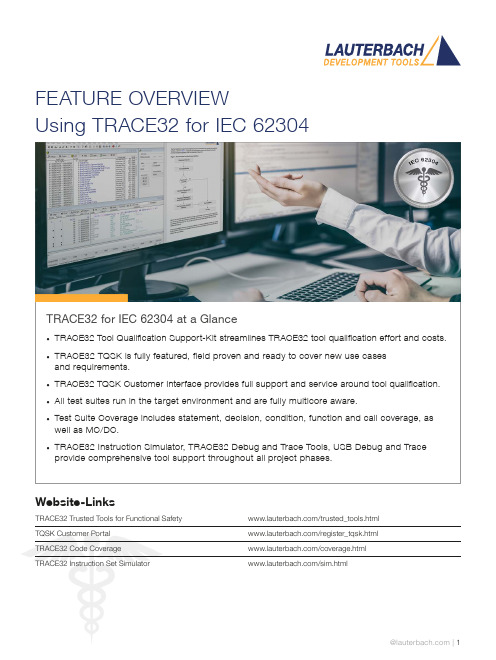
FEATURE OVERVIEWUsing TRACE32 for IEC 62304TRACE32 for IEC 62304 at a Glance• TRACE32 Tool Qualification Support-Kit streamlines TRACE32 tool qualification effort and costs.• TRACE32 TQSK is fully featured, field proven and ready to cover new use casesand requirements.• TRACE32 TQSK Customer Interface provides full support and service around tool qualification.• All test suites run in the target environment and are fully multicore aware.• Test Suite Coverage includes statement, decision, condition, function and call coverage, as well as MC/DC.• TRACE32 Instruction Simulator, TRACE32 Debug and Trace Tools, USB Debug and Trace provide comprehensive tool support throughout all project phases.Website-LinksTRACE32 Trusted Tools for Functional Safety /trusted_tools.htmlTQSK Customer Portal /register_tqsk.htmlTRACE32 Code Coverage /coverage.htmlTRACE32 Instruction Set Simulator /sim.htmlThe TRACE32 Tool Qualification Support-Kit (TQSK) provides everything needed to qualify use in safety-related software projects.Figure 1: The 2-stage qualification processCertification ArtifactsDocumentsTest SuiteTool Verification and Validation Supplement for Integration toOperational EnvironmentTest Suite DocumentsTest ReportTesting in Operational EnvironmentTest Report Testing inTSSTCTest Suite Simulator TriCore(paid)DSMDeveloper SafetyManualTSCTest Suite Coverage(free)TSDTest Suite Debug(free)$$TSSATest Suite Simulator Arm(paid)Test Suite SimulatorUpon customer request, Lauterbach also provides test suites for its Arm and TriCore Instruction Set Simulators. A qualified instruction set simulator is an accepted test environment in the software module testing phase of the project (see also figure 3) and offers the following advantages:• Product software qualification can start before product hardware is available.• The qualification of the product software can be well organized even in a distributed team, becauseeverything necessary is purely software-based.• If bottlenecks occur during this phase due to a lack of development hardware or debug/trace tools, additional test benches can be easily equipped with simulators.Test Suite DebugThe Test Suite Debug includes all basic debugging functionality such as target configuration, programming onchip and NOR flashes, loading programs, setting breakpoints and reading/writing of memory and variables.Figure 3: TRACE32 tool use in code coverage qualification。
TCL机型与遥控器对应表ok

型号
款式 RC-C09T RC-E16T RC-C16T RC-C12T RC-C12T
RC-F28T RC-038 RC-B01
RC-E09T RC-C14T RC-C14T
RC-C01T RC-C01T RC-C07T RC-C01T RC-C07T RC-B07T RC-B06T RC-E33T RC-B02T
TCL TCL TCL TCL TCL TCL TCL TCL TCL TCL TCL TCL TCL TCL TCL TCL TCL TCL TCL TCL TCL TCL TCL TCL TCL TCL TCL TCL TCL TCL TCL TCL TCL TCL TCL TCL TCL TCL TCL TCL TCL TCL TCL TCL TCL TCL TCL TCL TCL TCL TCL TCL TCL TCL TCL TCL TCL
RC-F64T RC-042
113 114 115 116 117 118 119 120 121 122 123 124 125 126 127 128 129 130 131 132 133 134 135 136 137 138 139 140 141 142 143 144 145 146 147 148 149 150 151 152 153 154 155 156 157 158 159 160 161 162 163 164 165 166 167 168 169
2901A 2129C 2511F 2515DZ 2515DZ 2516B 2516BI 2516BP 2516BZ 2516EF 2518E 2518EF 2518EW 2535A 2536F 2536G 2536W 2539D 2566B 2575D 2580DB 2906A 2906E 2906E 2909A 2909B 2909B 2910G 2910GW 2911 2911DI 2911DZ 2913A 2913E 2913EB 2913UI 2915DZ 2916D 2916P 2916P 2918E 2918EW 2919AZ 2926UI 2927D 2927D 2939D 2939DR 2939R 2939W 2952AL 2952B 2956D 2956D 2966A/G 2966DG 2966F
TK-使用说明书
第一节概述TK200井下通讯、控制、保护系统是在我厂TK100工作面及皮带通讯、控制一体化系统基础上,重新开发研制的新一代产品。
可实现工作面、顺槽皮带、大皮带等的保护,控制、沿线通话、故障检测、显示及报警等功能。
从工作面到顺槽,从单条运输皮带到整个矿井的所有固定皮带,从简单的皮带头尾搭接到“丁”字型、“山”字型搭接,从设备启、停控制到工作电流、电压显示、皮带速度检测和显示、煤仓煤位检测、显示、高低煤位停机,油温、油压、轴温等的检测和显示及计算机远程通信,故障自诊断等等,TK200均可提供全套解决方案。
(一)系统组成:TK200由以下设备及子系统构成:1.TK200控制、显示中心2.拉线急停、沿线闭锁、通话子系统。
3.智能输入、输出(用于远距离输入、输出)。
4.智能耦合器5.皮带控制器(待开发)6.皮带张紧(可由参数设置为自动张紧、手动张紧、朗艾道自动张紧等)7.传感器子系统(二)系统功能:TK200系统可完成:1.工作面各设备的启停状态检测和显示。
包括:(1)采煤机、前后部运输机、破碎机、转载机、泵、皮带的启停等。
(2)配接我厂的“TJ100设备工作电流检测仪”后,可对以上设备的工作电流进行检测、显示及过载后进行语言报警。
2.检测结果的显示控制计算机对以上参数检测后,在TK200控制中心的10.4”大屏幕彩色液晶平板显示器上显示出来。
(以图形、动画的形式显示设备启停情况,以不同的颜色表示过载情况。
)3.设备启停时间统计、显示。
4.设备启停控制。
通过按键,可对破碎、转载、前后部运输机及泵等设备进行启停控制。
5.报警设备启动前,以及发生各种故障时进行报警,报警时间的长短可以通过参数设定。
6.将工作面各设备工作状态和参数传输给井上,在井上计算机进行显示。
7.皮带控制包括六大保护,皮带启停、皮带张紧(可由参数设置为自动张紧、手动张紧或朗艾道型自动张紧)、软启动控制、电机温度检测和显示、皮带沿线拉线闭锁。
FAB2 系列智能控制器用户手册说明书

序言序言感谢您选购了本公司FAB2使用前花些时间阅读一下本手册,您将会更方便地使用本产品。
FAB2系列智能控制器是一种采用功能块(FBD)LCD液晶显示面板的智能控制器。
它将以往PLC工作大大地简化。
FAB2生活的每个空间。
本手册将详细介绍FAB2用方法。
注意:(1)不得影印或转载本手册全部或部分内容。
FAB2 Intelligent Controller目录目录第一章F A B2简介1.1 FAB2的结构 (1)1.2 规格型号 (2)1.3 FAB2特点 (3)第二章F A B2的安装与接线2.1 FAB2的安装 (5)2.1.1 FAB2的安装方法 (5)2.1.2 FAB2的安装尺寸 (5)2.2 FAB2的接线 (6)2.2.1 FAB2的电源接线 (6)2.2.2 FAB2的输入接线 (7)2.2.3 FAB2的输出接线 (8)第三章功能模块概述3.1 基本功能模块(GF) (11)3.1.1 AND (12)3.1.2 OR (13)3.1.3 NOT (13)3.1.4 NAND (14)USER'S MANUAL3FAB2 Intelligent Controller目录4.3.1.3 FAB2_Addr 读写/修改地址界面 (38)4.3.2 Set 设置界面 (38)4.4 编辑FAB2功能程序 (39)4.4.1 编程规则 (39)4.4.2 中间继电器 (40)第五章通讯连接5.1 FAB2 的下载口 (43)5.2 FAB2 的485 接口 (43)5.2.1 FAB2 的A1B1 接口 (43)5.2.1 FAB2 的A1B1 接口 (43)5.3 FAB2通讯模块使用说明 (45)第六章应用6.1 学校上课或者工厂上班铃声的控制 (47)6.2 楼梯、大厅或者走廊照明多功能开关 (49)6.3 自动门控制要求 (49)6.4 通风系统 (50)6.5 霓虹灯控制系统控制要求 (51)6.6 展示橱窗照明系统 (54)6.7 FAB2在楼宇管理中的应用 (55)6.8 FAB2在二极管耐压计数及包装流水线上的引用 (56)USER'S MANUAL5FAB2 Intelligent Controller目录3.1.6 帮助 (72)3.1.7 编辑 (72)3.1.8 搜索 (72)3.1.9 FAB2操作 (73)3.1.10 窗体 (73)3.2 工具栏 (74)3.2.1 标准工具栏 (74)3.2.2 控制工具栏 (74)3.3 模块库 (75)3.3.1 模块库操作 (77)3.3.2 模块分类 (77)3.3.3 模块属性的设置 (77)3.3.3.1 通用属性 (77)3.3.3.2 特殊属性设置 (78)第四章基本操作4.1 开启文档 (86)4.1.1 开启新文档 (86)4.1.2 开启原有文档 (87)4.2 编写功能图程序 (88)4.2.1 放置模块 (88)USER'S MANUAL7FAB2 Intelligent Controller目录2.6 AF-10MR-E2/AF-20MR-E2 (114)2.7 AF-10MT-GD2/AF-20MT-GD2 (115)附录3 保用说明 (117)附录4 关于USB驱动说明 (119)USER'S MANUAL9FAB2 Intelligent Controller第一章 FAB2简介第一章 FAB2简介FAB2系列PLC 是老FAB 系列PLC 的升级版,它也采用功能块FBD (Function Block Diagram)的方式编写程序,比起传统的PLC 编程(梯形图和指令)更为简单易学。
Phoenix Contact REG-K 12x230 16 手动模式下的开关器 说明书

The switch actuator REG-K/12x230/16 with manual mode (referred to below as the actuator ) can switch twelve loads via separate, floating make contacts.Y ou can also manually switch the connected loads with manual switches on the actuator without bus voltage.The actuator has a bus coupler. It is installed on a DIN rail, with the bus connection made via a bus connecting terminal. It is supplied with power from the bus voltage. A data rail is not required.For your safetyHAZARD OF ELECTRIC SHOCK, EXPLOSION, OR ARC FLASHSafe electrical installation must be carried out only by skilled professionals. Skilled professionals must prove profound knowledge in the following areas:•Connecting to installation networks •Connecting several electrical devices •Laying electric cables•Connecting and establishing KNX networks •Safety standards, local wiring rules and regulations Failure to follow these instructions will result in death or serious injury.RISK OF FATAL INJURY FROM ELECTRIC SHOCK The output may carry electrical current even when the load is switched off.•When working on the device: Always disconnect the device from the supply by means of the fuse in the in-coming circuit.•Even if the manual switch is in the …OFF“ position, aKNX telegram can switch the connections to being live at any time. Before working on the device, always diconnect the fuse in the incoming circuit from the supply.Failure to follow these instructions will result in death or serious injury.Getting to know the switch actuatorA Bus connecting terminal, max. 4 core pairsB Programming LED (red LED)C Programming buttonD Cable coverE Operating LED (green LED)F Manual switchG Screw terminals1Set the actuator onto the DIN rail.2Connect KNX.¼WARNINGRisk of fatal injury from electrical current. The device could become damaged.Safety clearance must be guaranteed inaccordance with IEC 60664-1. There must be at least 4 mm between the individual cores of the 230 V supply cable and the KNX line.Connections, displays and operatingelementsMounting the actuatorRISK OF FATAL INJURY FROM ELECTRIC SHOCKVoltage may be present at the outputs when the mains voltage is connected to the system.If subjected to strong vibrations during transportation, the switch contacts might change to the enabled state.After connecting the bus voltage, set the relays of the channels to the position desired simply by switching …On/Off“ or by changing the manual switch to …OFF“.Failure to follow these instructions will result indeath or serious injury.3Connect the bus voltage.4Switch the relays of the channels on and offmanually once with the manual switches.5Connect the load.The cables to the loads as well as the system voltages (L1, L2 or L3) are connected via screw terminals for max. 16 A. Every two L connections are bridged internally.6Connect the mains voltage.Now you can check the functionality of the actuator and the connected loads without having to load the application from the ETS. (See the "Operating the actuator" section.)1Press the programming button.The programming LED lights up.2Load the physical address and application into thedevice from the ETS.The programming LED goes out.The operating LED lights up: The application was loaded successfully, the device is ready for operation.Putting the actuator into operationSpaceLogic KNXSwitch actuator REG-K/12x230/16 with manual modeOperating instructionsArt. no. MTN648493Normally, you control connected devices using push-buttons or by remote control. However, you canmanually switch each of the actuator's channels on and off directly at the manual switches.Schneider Electric Industries SAS 35 rue Joseph Monier Rueil Malmaison 92500 FranceIf you have technical questions, please contact the Cus-tomer Care Centre in your /contactOperating the actuatorT echnical dataExternal auxiliary voltage:NonePower supply from bus:DC 24V/max. 10mA Insulation voltage:AC 4 kV between bus and 230V ACSwitch contacts:12 x make contacts, floating Nominal voltage:AC 230V , 50 to 60Hz Nominal current:16A, cos ϕ = 0.6Connected loadIncandescent lamps:AC 230V , max. 3600W with 10,000 switching cyclesHalogen lamps:AC 230 V , max. 2500 W with 10,000 switching cycles Fluorescent lamps:AC 230V , max. 2500VA, parallel-compensated,with 5,000 switching cycles Capacitive load:AC 230V , 16A max. 200μF with 5,000 switching cycles Minimum loads:≥ 24V DC, 100mASwitching frequency:max. 10 per minute at nominal loadAmbient temperature Operation:-5°C to +45°C Storage:-25°C to +55°C Transport:-25°C to +70°CEnvironment:The device is designed for use at a height of up to 2000m above sea level (MSL).Max. humidity:93%, no moisture condensationOperating elements:Programming button,twelve manual switches for manual operationDisplay elements:Red LED for programming check,green LED to indicate device availabilityConnections Bus:via two 1 mm pins for bus connecting terminal Outer conductor:eleven 3-gang screwterminals (1–11) and one 2-gang screw terminal (12) for each max. 2.5mm 2Installation width:12depth units = approx. 216mmEC guidelines:Corresponds to Low-Voltage guideline 73/23/EEC and EMC guideline 89/336/EECSchneider Electric -ContactSchneider Electric Limited Telford, TF3 3 BL, UKUK RepresentativeStafford Park 5V 6484-562-02 11/21。
基于HyperMesh二次开发的静刚度分析程序pdf

基于HyperMesh 二次开发的静刚度分析程序作者:樊红光昝建明摘要:静刚度分析是汽车研发CAE 分析中的一项基础、繁琐而又十分重要的工作。
本文利用TCL 语言对HyperMesh 进行二次开发,将静刚度分析流程化,程序化,既节省了工作时间,同时也提高了分析的准确率,一致性。
1 前言在汽车研发的CAE 分析工作中,静刚度分析是一项基础而重要的内容。
静刚度分析内容多,工作量大,且分析流程类似,操作大量重复,枯燥繁琐;同时,静刚度分析项目不同工况的载荷大小、约束及其它操作和参数存在较多细节上的差异,工程师在完成该类分析时,容易出现人为的遗漏和错误,还需耗费大量时间去检查;另外,静刚度分析对应的分析规范多,并且由于分析方法的改进,分析规范也处在不断的更新过程之中。
为了确保分析方法与最新的分析规范相一致,工程师每次分析之前均需要查阅和确认最新的分析规范。
不仅耗时费力,而且容易出错。
这样就很难保证分析规范严格高效地执行。
本文利用TCL/TK 语言,对HyperMesh 进行二次开发,将基本的静刚度分析项和分析规范集成到HyperMesh 当中,固化分析参数与步骤,最大程度地减少人工干预。
实现了静刚度分析流程自动化,很好的解决了静刚度分析面临的上述问题,大大提高了工作效率。
为了便于推广应用,还编写了相应的使用帮助文档《静刚度/模态分析程序使用手册》,便于CAE 工程师快速学习和查阅。
2 程序功能介绍 程序界面如图1所示,在HyperMesh 菜单栏上添加了一个NVH 下拉菜单,菜单分为二级,第一级为静刚度分析和模态分析,静刚度分析的二级菜单则为20多项常规的刚度分析内容,模态分析的二级菜单则为自由模态分析和约束模态分析。
网格模型导入后,选择二级菜单中的相关分析项,程序将提示并引导用户作一些简单的输入,程序将自动完成其它的处理工作,并生成求解器输入文件,同时在HyperMesh 中添加了一个工具条,使得用户可以直接在工具条上点击相应按钮,即可启动求解器进行分析,并将结果文件保存到用户指定的目录当中,如果用户一次选择了多个分析项,并在最后点击工具条上的启动求解器计算按钮,则程序生成批处理文件,可使求解器批量处理这些分析项。
NAMD入门教程(一)-图文

NAMD入门教程(一)-图文预定目录1.分子动力学模拟概论1.1分子动力学模拟的发展1.2分子动力学模拟的基本原理1.3分子动力学模拟相关软件2.分子动力学入门2.1基本设置2.2生成蛋白质结构文件(PSF)2.3蛋白质的溶质化2.4球状水体中泛素(Ubiquitin)的分子动力学模拟2.5立方水体中泛素(Ubiquitin)的分子动力学模拟2.6简单的结果分析3.分析方法3.1平衡态分子动力学模拟分析3.1.1每个残基的RMSD值3.1.2麦克斯韦-波尔兹曼(Ma某well-Boltzmann)能量分布3.1.3能量分析3.1.4温度分布3.1.5比热分析3.2非平衡态分子动力学模拟分析3.2.1热扩散3.2.2温度回音4人工操纵的分子动力学模拟(SMD)4.1除去水分子4.2恒速拉伸4.3恒力拉伸4.4结果分析1.分子动力学模拟概论分子动力学模拟(MolecularDynamicSimulation)是指利用计算机软件,根据牛顿力学的基本原理,模拟大分子的相互作用和运动变化的研究方法。
生命科学的研究往往离不开各种仪器,试管和活的有机体,通过实验手段研究生命现象背后的规律。
那么,为什么我们要将生命大分子抽象成二进制数据,由计算机软件模拟其行为呢?首先,从理论基础上讲,我们能够使用计算机模拟生物大分子的行为。
生物体系非常复杂,但生物大分子如蛋白质,脂肪,多糖等也是许多原子由化学键连接起来形成的,所有原子的运动规律都符合量子力学方程,在较大尺度上也近似符合牛顿力学方程,它的行为是要受物理学基本规律支配的。
因此我们可以将利用纯数学的手段,近似模拟生物大分子的行为.其次,从研究需要上讲,我们不仅希望从宏观上研究生命大分子溶液体系的行为,还想直接研究单个生物大分子在原子尺度上的行为,而这是目前的实验仪器难以达到的。
比如,我们希望直接研究蛋白质从伸展的肽链折叠成球形的具体过程,使用仪器手段只能收集到间接的数据,但使用软件模拟则可以形象直观的模拟出整个折叠过程,可以具体求算每个键能、键角的变化,研究某几个氨基酸残基之间的相互作用,以及对蛋白质折叠的意义。
MagicLinux开发入门指南(二)MagicLinux开发总部
MagicLinux开发入门指南(二)MagicLinux开发总部2.4 让这个新的gcc环境能够真正的工作起来编译器、连接器、程序库都创建好了,可以开始创建MagicLinux 了吧?呵呵,不行!这个新的gcc环境还没有真正工作起来呢。
不信,我们做一个实验试试。
编写一个最简单的C代码:#echo 'main(){}' > ttt.c#gcc ttt.c#readelf -l a.out看看结果,是不是有一行类似下面的内容:[Requesting program interpreter:/lib/ld-linux.so.2]这是不对的。
readelf是分析elf可执行文件(Linux下可执行文件的格式)格式的工具,-l选项是用来显示可执行文件各段头内容的,通过它可以了解一个可自行文件的依赖关系。
上面的结果表明新的gcc产生的可执行文件还是依赖于你现有系统的ld-linux.os.2,这是glibc的一部分。
这是为什么?该怎么办?问题在创建binutils是就已经作了一些解决,但是还没有完全解决。
回想一下,在安装完binutils后,还做了如下操作:#make -C ld clean#make -C ld LIB_PATH=/toolchain/lib#cp -v ld/ld-new /toolchain/bin创建了一个ld-new,而且还复制到了/toolchain/bin下,这个ld-new就是关键,执行下面操作:#mv -v /toolchain/bin/{ld,ld-old}#mv -v /toolchain/$(gcc -dumpmachine)/bin/{ld,ld-old}#mv -v /toolchain/bin/{ld-new,ld}#ln -sv /toolchain/bin/ld /toolchain/$(gcc -dumpmachine)/bin/ld这就使得接下来创建的程序都使用/toolchain/lib中的程序库了。
安徽天康涡街产品说明书 v2.5-5P

张剑_基于HyperGraph二次开发的IPI分析后处理程序
基于HyperGraph二次开发的IPI分析后处理程序IPI Postprocessing Program Based on HyperGraphSecondary Development张剑樊红光昝建明(长安汽车工程研究总院重庆400120)摘要:IPI分析是汽车研发CAE分析中的一项基础又十分重要的工作。
然而,由于涉及到的工况多,计算结果数据量大,需要绘制大量的表格和图表,因此后处理和撰写分析报告的工作量很大,本文针对这个问题,利用TCL语言对HyperGraph进行二次开发,实现IPI分析后处理自动化,既大大提高了工作效率,同时也提高了后处理工作准确性,一致性。
关键词:IPI分析后处理HyperGraph 二次开发Abstract:IPI analysis in the automotive CAE analysis is very important work. However, it relates to many working conditions, and need to draw a large number of tables and charts with large amount of calculated data,so post-processing and writing analysis report needs a lot of time . Considering this situation, the post-processing program for IPI analysis based on HyperGraph secondary development is developed. It does not only greatly improve the efficiency, but also improve the post-processing accuracy and consistency of the IPI post-processing.Key Words:IPI Postprocessing, HyperGraph, Secondary Development1前言在汽车研发的CAE分析工作中,IPI分析后处理是一项基础而重要的内容。
利用TCL实现用户约束文件的解析
利用TCL实现用户约束文件的解析李卿;惠锋;董志丹【摘要】用户约束在EDA工具使用中至关重要,是其重要组成部分.针对用户约束规则复杂、多变的问题,该文讲述了一种利用TCL实现用户约束文件解析的方法.首先声明约束规则,然后定义解析规则,最后读取用户约束文件并逐行解析.当约束规则更改或者添加新的约束规则时只需要修改或添加相应的声明、解析规则即可,从而达到设计的简洁性、灵活性、可扩展性,在自主研发EDA工具中具有较大的实际应用价值.【期刊名称】《电子与封装》【年(卷),期】2018(018)005【总页数】4页(P41-44)【关键词】用户约束;TCL语言;文件解析;电子设计自动化【作者】李卿;惠锋;董志丹【作者单位】无锡中微亿芯有限公司,江苏无锡214072;无锡中微亿芯有限公司,江苏无锡214072;无锡中微亿芯有限公司,江苏无锡214072【正文语种】中文【中图分类】TN4021 引言随着 FPGA(Field-Programmable Gate Array)的发展,对其工作频率和处理速度的要求越来越高。
器件处理速度的提高意味着逻辑设计时对时钟信号方面的要求和处理也变得更严格,需要通过附加约束来控制逻辑的综合、映射、布局和布线,以减少逻辑和布线的传输延时,从而提高工作频率。
因此,用户约束在电子设计自动化(Electronic Design Automation,EDA)工具使用中不可或缺,是自主研发EDA工具的重要组成部分。
由于用户约束规则复杂繁多、灵活多变,如何简单、有效地实现约束文件的解析至关重要,本文提出一种采用TCL(Tool Command Language)语言来实现用户约束文件的解析方法。
TCL是一种基于字符串的解释型命令语言,是一种简明、高效、可移植性好的编程语言,具有可扩展、支持重用、简单易学等特点。
TCL语言作为应用的粘合剂,能够无缝地将很多应用集成在一起,并且每一条TCL语句都可以理解成命令参数形式[1]。