穿孔式电流传感器BA05等系列说明书
银河电气CSA801-P031T01 电流传感器使用说明书

CSA801-P031T01电流传感器使用说明书V1.2感谢您选用银河电气CSA801-P031T01电流传感器本手册为湖南银河电气有限公司产品CSA801-P031T01电流传感器用户手册,本手册为用户提供安装调试、操作使用及日常维护的有关注意事项,在安装、使用前请仔细阅读。
本手册随产品一起提供,请妥善保管、以备查阅和维护使用。
声明我们非常认真的整理此手册,但我们对本手册的内容不保证完全正确。
因为我们的产品一直在持续的改良及更新,故我方保留随时修改本手册的内容而不另行通知的权利。
同时我们对不正确使用本手册所包含内容而导致的直接、间接、有意、无意的损坏及隐患概不负责。
安全操作知识◆产品使用前,请您务必仔细阅读用户手册。
◆需对产品进行搬动时,请您务必先断电并将与之相连的所有连接线缆等拔掉。
◆如果发现机壳、稳固件、电源线、连接线缆,或相连的设备有任何损坏,请您立即将装置与电源断开。
◆如果对设备的安全运行存在疑虑,应立即关闭设备和相应附件,并在最快时间内与本公司技术支持部门取得联系,沟通解决。
!安全警示电流传感器不允许开路使用,即母线有电流或传感器已上电的状态下,都不允许断开输出端;仅母线无电流且传感器未上电的状态下,才可以断开传感器的电流输出端,否则有感应高压,发生电击的危险!1.产品概述CSA801-P031T01是一种能在原边、副边完全隔离条件下测量直流、交流、脉冲以及各种不规则波形的电流传感器,它主要用于要求准确度高的计量检定和计量校准领域,以及要求高灵敏度、高稳定性和高可靠性的电能质量分析、功率分析仪、医疗、航空航天、导弹、舰艇等领域。
2.技术特点●极高的准确度●极好的线性度●极高的稳定性●极高的灵敏度●极高的分辨率●极低的温度漂移●极低的失调电流●极低的插入损耗●抗干扰能力强●响应速度快●极低的噪声●极小的角差●宽频带●模拟量输出3.应用场合●计量检定与校准●实验室电流测量●仪器仪表(如功率分析仪)●医疗设备(如核磁共振MRI)●电池组检测●电力控制●电源●舰船●新能源●轨道交通●航空航天●工业测量4.电气性能项目符号测试条件数值单位最小标称最大原边额定电流I PN-- -- ±800 -- Adc 测量范围I PM1分钟/小时-- -- ±960 Adc 工作电压V c全范围±18 -- ±24 Vdc 电流消耗I c I PM范围内±40 ±570 ±680 mA 电流变比K N输入:输出1500:1 -- 额定输出电流I SN原边额定电流--±533.33--mA 测量电阻R MVc:±18,I PN:±800 Adc 0 -- 3 ΩVc:±24,I PM:±800 Adc 0 -- 12 Ω5.精度-动态参数项目符号测试条件数值单位最小标称最大精度X e25±10℃-- -- 10 ppm 比差误差X Ge -- -- 100 ppm 角度误差X Pe-- -- 0.01 crad 线性度εL-- -- -- 2 ppm温度漂移系数TCI OUT -- -- -- 0.1 ppm/K时间漂移系数TT -- -- -- 0.2 ppm/month 供电抗干扰TV -- -- -- 1 ppm/V 零点失调电流I o25±10℃-- -- 2 ppm 零点失调电流I oT全工作温度范围内-- -- ±5 ppm 纹波电流I n DC-10Hz -- -- 0.5 ppm动态响应时间t r-- -- -- 1 us电流跟随速度di/dt -- 100 -- -- A/us频带宽度(- 3 dB) F -- 0 -- 250 kHz6.一般特性项目符号测试条件数值单位最小标称最大工作温度范围T A-- -10 -- +70 ℃存储温度范围T S-- -25 -- +85 ℃输出状态指示信号--当输出状态指示信号灯(绿色LED)亮时,表示产品工作正常,且母排输入的电流没有超出其承受能力,这时与OD门电路D极相连的DB9插座第8脚为低电平;当输出状态指示信号灯灭时,表示产品工作不正常或母排输入的电流值超出其承受能力,这时DB9插座第8脚为高电平。
直流电流传感器说明书

高精度电流传感器规格书AIT400-SG深圳市航智精密电子有限公司AIT400-SG 高精度电流传感器多点零磁通技术系统应用于现有高精度直流传感器技术之中,激励磁通闭环控制技术、自激磁通门技术及多闭环控制技术相结合,实现了对激励磁通、直流磁通、交流磁通的零磁通闭环控制,并通过构建高频纹波感应通道实现了对高频纹波的检测,从而使传感器在全带宽范围内拥有比较高的增益和测量精度。
产品图片核心技术性能特点◇激励磁通闭环控制技术◇原、副边隔离测量◇自激退磁技术◇出色的线性度和准确度◇多点零磁通技术◇极低的温漂◇多级量程自动切换技术◇极低的零漂◇温控补偿技术◇强抗电磁干扰能力◇宽频带和低响应时间应用领域◇医疗设备:扫描仪、MRI ◇轨道交通:高速列车、地铁、有轨无轨电车◇电力:变流器、逆变器◇测试仪器仪表:功率分析仪、高精密电源◇新能源:光伏、风能◇汽车:电动汽车◇舰船:电力驱动舰船◇航空航天:卫星、火箭◇计量:检定与校准◇智能电网测量:发电、电池监测、中低压变电站◇工业控制:工业电机驱动、UPS 、焊接、机器人、吊车、电梯、滑雪升降机电气性能项目符号测试条件最小值标称最大值单位原边额定直流电流I PN_DC— — ±400 — Adc 原边额定交流电流*I PN— — 282 — Aac 原边过载电流I PM1分钟— — ±480 Adc 工作电压V C— ±14.2 ±15 ±15.8 V 功耗电流I PWR原边额定电流±30 ±230 ±270 mA 电流变比K N输入:输出2000:1 2000:1 2000:1 — 额定输出电流I SN原边额定电流— ±0.2 — A 测量电阻R M见图1 0 5 12 Ω* :指交流有效值精度测量项目符号测试条件最小值标称最大值单位准确度X G输入直流,25±20ºC — — 10 ppm 线性度εL— — — 2 ppm 温度稳定性T C— — — 0.1 ppm/K 时间稳定性T T— — — 0.2 ppm/month 供电抗干扰T V— — — 1 ppm/V 零点失调电流I O@25ºC — — 1(用户可调零)ppm 纹波电流I N DC-10Hz — — 0.5 ppm动态响应时间t r di/dt=100A/us,上升至90%I PN— — 1 us 电流变化率di/dt — 100 — — A/us频带宽度(-3dB) F — 0 — 500 kHz零点失调电流I OT全温度范围— — ±5 μA安全特性项目符号测试条件数值单位隔离电压/ 原边与副边之间Vd 50Hz,1min 5 KV瞬态隔离耐压/ 原边与副边之间Vw 50us 10 KV爬电距离/ 原边与外壳之间dCp — 11 mm电气间隙距离/ 原边与外壳之间dCi — 11 mm 相比漏电起痕指数CTI IEC-60112 600 V一般特性项目符号测试条件最小标称最大单位工作温度范围T A—-40—+85ºC 质量m—1060±20g负载电阻使用说明图:负载电阻与测量电流关系图运行状态说明◇正常运行时,绿灯常亮:设备上电后,当设备正常工作时,绿色指示灯常亮,D-Sub9接口的第3脚和第8脚导通。
三脚线交流电流传感器说明书

Magnetic Cylinder Sensors with Mounting SystemBMF 305PNP connector PNP connector NPN connector NPN connectorPNP cable PNP cable NPN cableNPN cableWiring diagramsNONCassociated mounting brackets for BMF 305 can be found onpage 868.Additional cable lengths on requestTemperature load curveThe universal sensor for position monitoring on large actuators66BNBKWHBUV-Twin PNP connectorMagnetic Cylinder Sensors with Mounting SystemBMF 305surfaceSuitable mounting brackets for BMF 305 can be found on page 868Magnetic cylinder sensors Magnetic cylinder sensors with mounting system BMF 103BMF 303BMF 305BMF 21Total Productive Maintenance Magnetic cylinder sensors with a compact design Magnetic cylinder sensors with special properties Magnetic sensors for object detection Magneto-inductive displacement sensors for analog position measurementAccessories for magnetic cylinder sensorsBMF 305Magnetic Cylinder Sensors with Mounting SystemBMF 305 mounting bracketBMF 305BMF 305BMF 305Magnetic Cylinder Sensors with Mounting SystemBMF 305 mounting bracketMagnetic cylinder sensorsMagnetic cylinder sensors with mounting system BMF 103BMF 303BMF 305BMF 21Total Productive Maintenance Magnetic cylinder sensors with a compact design Magnetic cylinder sensors with special properties Magnetic sensors for object detectionMagneto-inductive displacement sensors for analog position measurement Accessories Type A Type AType B Type BMagnetic Cylinder Sensors with Mounting SystemBMF 305 mounting bracketMagnetic Cylinder Sensors with Mounting SystemBMF 305 mounting bracketturn, adjust position, tighten.sensor, the adjusted switching point is permanently set by the mounting bracket.Recommended accessories (please order separately)Special accessories for magnetic cylinder sensors, such as installation tools, cable clips, or tube cuffs, can be found in this catalog on page 910.Magnetic cylinder sensors Magnetic cylinder sensors with mounting system BMF 103BMF 303BMF 305BMF 21Total Productive Maintenance Magnetic cylinder sensors with a compact design Magnetic cylinder sensors with special properties Magnetic sensors for object detection Magneto-inductive displacement sensors for analog position measurement Accessories for magnetic cylinder sensors。
安科瑞穿孔式电流变送器

穿孔式电流变送器BA50-AI/I(V)安科瑞徐孝峰江苏安科瑞电器制造有限公司江苏江阴2144051产品概述BA系列穿孔式电流变送器采用电磁感应原理,对电网中的交流电流进行实时测量,采用精密恒流技术和线性温度补偿技术,将其隔离变换为标准的直流信号输出。
为PLC或DCS系穿孔式电流变送器统一提供电流信号。
采用24伏或12伏安全电压供电,具有过载能力强、高精度、高隔离、高安全性、低功耗等特点,可广泛用于工业自动化领域。
-穿孔式电流变送器BA50-AI/I(V)穿孔式电流变送器2型号说明3技术参数BA05电流传感器BA10电流传感器BA20电流传感器BA50电流传感器5、接线示例如图所示穿心输入Iac,电流输出型传感器的输出为共地电流源,电压输出型传感器的输出为共地电压源。
图中RL是用户负载,输出为电流时,负载≤400Ω(12V供电)或≤800Ω(24V供电);输出为电压时负载≥1kΩ。
6实际应用下面以无锡某空调设备生产公司为例,介绍BA系列穿孔式电流变送器在工业制冷设备中的应用。
无锡某空调设备生产公司是一家致力于生产、销售、维护工业制冷设备为一体的企业,产品主要包括风冷式冷水机组、水冷螺杆式冷水机组、水冷箱式冷水机组、风冷式油冷机组,冷冻除湿机等。
产品广泛适用于医药、化工、食品、注塑、电子、造纸印刷等多个行业。
该单位生产的水冷式冷水机组(图1)采用名牌压缩机及电控元件加工制造,配套壳管式冷凝器及不锈钢水箱式、板式、壳管式蒸发器,外形美观、冷量充足、效能高、易于维护。
图1:水冷式冷水机组其产品内部的电器控制部分,机组启动与控制的所有元件均安装在电控箱(图2)内,由工厂接线并完成功能测试,电器控制部分包括:文本控制器、主接触器、塑壳断路器等。
图2:水冷式冷水机组内部构造图制冷机组采用微电脑控制,主芯片与江苏安科瑞BA系列穿孔式电流变送器相连,通过监测机组电流间接监测机组的运行功率,内部数据在机组外面的液晶屏上实现可视化,并配置多重保护装置,能准确控制运行状况,稳定性高。
德力西 CDBA(Z)-63B特殊应用物联网断路器 使用说明书

CDBA(Z)-63B 物联网断路器使用说明书目录1主要用途及适用范围 (1)2产品特点、型号及含义 (1)2.1产品特点 (1)2.2产品型号及含义 (1)2.3面板介绍 (2)3正常工作条件和安装条件 (3)4正常贮存和运输条件 (3)5安装及接线 (4)5.1安装示意图 (4)5.2接线示意图 (5)6技术特性 (6)6.1分类 (6)6.2主要技术参数 (6)6.3主要功能描述 (6)6.4主要技术性能 (6)7外形及安装尺寸 (7)8安装和使用(维护) (7)10注意事项 (8)11开箱检查 (9)12订货须知 (9)13公司承诺 (10)1主要用途及适用范围CDBA(Z)物联网断路器(以下简称CDBA(Z))是一种集保护功能、报警功能、控制功能、计量功能、事件记录和通讯功能为一体的物联网断路器,其适用于交流50/60Hz和直流,CDBA-63B额定电压为AC 230/240V,CDBAZ-63B额定电压为DC 48/60/80V,额定电流至63A及以下的电路中。
2产品特点、型号及含义2.1产品特点a) 保护功能:过载保护、短路保护、过压保护、欠压保护、过欠压自恢复,缺相保护;b) 报警功能:过载、过压、欠压、过功率、过电量,控制器过温保护;c) 控制功能:远程控制分合闸,可定时控制分合闸,远程自动送电,功率限定;d) 计量功能:电参数计量电参数计量(电流、电压、功率(无功,有功,视在)、频率、功率因数、操作次数、电量、控制器温度);e) 事件记录:分合闸操作记录,过载故障记录,过欠压故障记录;f) 通讯功能:支持向上RS485通讯。
2.2产品型号及含义行业专用壳架等级Z表示直流,无代号表示交流设计代号断路器德力西电气2.3面板介绍图1 面板介绍说明:1公司商标2产品LOGO 3额定电流 4 产品型号5触头指示6负载端7 N极8 状态指示9手自和维修转换指示10 出线端11 额定电压12 使用类别及脱扣类型13 分断能力14 参考标准15 RS485通信端口16 接线原理图17 3C标志注:正常分合闸手柄时,如指示窗不同步运动,请停止使用。
东方仪表 ETCR068AD 交直流钳形电流传感器 用户手册说明书

ETCR 068AD 交直流钳形电流传感器用户手册注意事项:感谢您购买了本公司的ETCR068AD交直流钳形电流传感器,为了更好地使用本产品,请一定:——详细阅读本用户手册。
——严格遵守本手册所列出的安全规则及注意事项。
u任何情况下,使用本传感器应特别注意安全。
u注意本传感器面板及背板的标贴文字及符号。
u保持钳口清洁,定期保养。
u传感器有破裂、断线禁止使用。
u电池电压偏低,请及时更换电池,长时间不用本仪表,请取出电池。
u更换电池,请注意电池极性;若外接电源,注意接线的正负。
u请勿于高温潮湿,有结露的场所及日光直射下长时间放置和存放传感器。
u使用、拆卸、维修本传感器,必须由有授权资格的人员操作。
u由于传感器原因,继续使用会带来危险时,应停止使用,并封存,由有授权资格的机构处理。
u传感器及手册上的“”危险标志,使用者必须依照指示进行安全操作。
u手册中”极其危险标志,使用者必须严格依照指示进行安全操作。
一.简介ETCR068AD交直流钳形电流传感器适用于交直流电流、相位、电能、功率、功率因数等检测。
采用最新CT技术,钳头无任何裸露金属导体,便携式钳形设计,不必断开被测线路,非接触测量,安全、快速,其钳头铁芯选用特殊合金,确保了常年无间断测量的高精度、高稳定性、高可靠性。
传感器可以连接相位检测分析仪、工业控制装置、数据记录仪、示波器、谐波分析仪、电力质量分析仪、高精度数字多用表等。
广泛适用于电力、通信、气象、铁路、油田、建筑、计量、科研教学单位、工矿企业等领域。
二.规格功能交直流电流、相位、电能、功率、功率因数等检测电源碱性干电池 6LR61 9VDC (可以外接电源)额定电流15mA检测方式钳形CT,非接触测量钳口尺寸φ68mm量程DC 0~2000A;AC 0~1000A分辨率0.1A AC/DC信号输出1mV/1A精度等级±2.0%FS (23℃±2℃,70%RH以下,导线处于钳口中心位置)相位误差≤3°(AC 50Hz/60Hz;23℃±2℃)清零按ZERO键可以清零,消除地磁场对直流检测的影响输出接头φ3.5mm音频插头/BNC插头/4.0mm双香蕉插头(按客户要求)输出线2芯屏蔽线,长2m导线位置被检测导线处于钳口中心位置,偏离中心位置误差最大增加1.5%rdg频率响应交流:45Hz~400Hz线路电压AC 600V以下线路测试电池电压当电池电压降到7.2V时,电池电压低LED灯亮,提醒更换电池仪表尺寸长224mm×宽115mm×厚43mm仪表质量 515g工作温湿度 -15℃~45℃;80%rh 以下存放温湿度 -10℃~60℃;70%rh 以下绝缘强度 AC 3700V/rms(铁心与外壳之间)适合安规 IEC1010-1、IEC1010-2-032、污染等级2、CAT Ⅲ(600V)三.原理及结构采用分割式铁芯和霍尔元件(hole element)组合,能同时检测交流和直流电流,当被测电流I 通过传感器时,霍尔元件感应输出一个霍尔电压V H ,可以通过检测霍尔电压V H ,来计算被测试电流I ,霍尔电压V H 比例于被测试电流I ,经传感器对应输出为:1mV/1A ,即输入1A 电流,比例输出1mV 电压。
安智传感器仪表说明书

2.配线注意事项:1)热电偶输入的场合,请使用规定的补偿导线;如果被测量设备为金属加热物请使用带绝缘的热电偶。
2)热电阻输入的场合,请使用导线电阻较小的,且(3线式)无电阻差的线材,但总长度应在5m 内。
3)为了避免噪声干扰的影响,请将输入信号远离仪器电源线、动力电源线、负载线进行配线。
4)为了减小动力电源线以及大负载电源线对本产品的影响,请在容易受到影响的场合,建议使用噪声滤波器。
如果使用噪声滤波器,请务必将其安装在接地的盘面等上,并使噪声滤波器输出侧与电源端子间的配线最短;不要在噪声滤波器输出侧的配线上安装保险丝、开关等,否则会降低滤波器的效果。
5)本产品在投入电源时到有输出时间约为5秒。
如果有联锁动作的电路等信号使用的场合,请使用延时继电器。
6)变送输出线请尽量使用带屏蔽层的双绞线;确保信号可靠稳定。
7)远距离RS485通讯线请使用带屏蔽层的双绞线,并将屏蔽层在主机侧接地处理;确保通讯可靠稳定。
8)本产品没有保险丝;需要的场合请按额定电压250V,额定电流1A 配置,保险丝种类:延时保险丝。
9)请使用适合的螺丝力及适合的压接端子端子螺丝尺寸:M4X8(带7.0X7.0方座)推荐拧紧力矩:0.7N.m合适线材:0.25~1.65mm 的单线或多芯软线10)请不要将压接端子或裸露线部分与相邻的端子接触。
智能传感器仪表说明书四、主要技术参数三、常规型号说明二、仪表型号SF 系列传感器表C:版本辅助电压:B: DC 24V 空白: 无T:温度传感器信号输入 空白:电压、电流输入通讯功能:0:无通讯 8: RS 485通讯 变送功能:I: DC 4-20MA变送输出 空白:无外形尺寸:3: 72W*36H*70.5L 4: 48W*48H 6: 48W*96H 7: 72W*72H 8: 96W*48H 9: 96W*96H 16:80W*160H 80:160W*80H 报警路数:空白: 无报警 2: 两路 3: 三路 报警类型:A :无报警 R:继电器报警输出输入信号4~20mA/0~10V4~20mA/0~10V 4~20mA/0~10V 4~20mA/0~10V 4~20mA/0~10V TC/RTD/mV/RT TC/RTD/mV/RT TC/RTD/mV/RT TC/RTD/mV/RT TC/RTD/mV/RT SF□-A0SF □-R20BSF □-R28BSF □-IR20BSF □-IR28BSF □-A0-T SF □-R20B -T SF □-R28B -T SF □-IR20B -T SF □-IR28B -T 22222222●●●●●●●●●●●●●●●●报警点数辅助电压变送输出485通讯型号1、电气参数表:3、隔离模式框图:五、通用面板名称1)在正常测量模式下,且参数2)进入参数3)4)在使用CAS、CAK 标定功能前,长按“SET”+“ ”(确保PSB=0)。
ETCR040、040A、040B 高精度钳形漏电流传感器 用户手册说明书
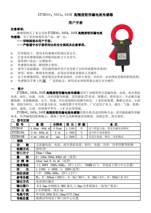
ETCR040、040A、040B高精度钳形漏电流传感器用户手册注意事项:感谢您购买了本公司的ETCR040、040A、040B高精度钳形漏电流传感器,为了更好地使用本产品,请一定:——详细阅读本用户手册。
——严格遵守本手册所列出的安全规则及注意事项。
u任何情况下,使用本传感器应特别注意安全。
u注意本传感器面板及背板的标贴文字及符号。
u保持钳口清洁,定期保养。
u传感器有破裂、断线禁止使用。
u请勿于高温潮湿,有结露的场所及日光直射下长时间放置和存放传感器。
u使用、拆卸、维修本传感器,必须由有授权资格的人员操作。
u由于传感器原因,继续使用会带来危险时,应停止使用,并封存,由有授权资格的机构处理。
u传感器及手册上的“”危险标志,使用者必须依照指示进行安全操作。
一.简介ETCR040、040A、040B高精度钳形漏电流传感器适用于高精度的交流漏电流、电流、高次谐波电流、相位、电能、功率、功率因数等检测。
采用最新CT技术,便携式、钳形设计,不必断开被测线路,非接触测量,安全、快速,可以连接相位检测分析仪、工业控制装置、数据记录仪、示波器、谐波分析仪、电力质量分析仪、高精度数字多用表等。
广泛适用于电力、通信、气象、铁路、油田、建筑、计量、科研教学单位、工矿企业等领域。
ETCR040、040A、040B高精度钳形漏电流传感器其钳头铁芯选用特殊合金,采用最新磁性屏蔽技术,外界磁场的影响极小,确保了常年无间断测量的高精度、高稳定性、高可靠性。
二.型号区别型号量程分辨率匝比屏蔽备注ETCR040 0.00mA~300A AC0.01mA 1:2400 有抗干扰能力强,更适合漏电流测试ETCR040A 0.0A~600A AC 0.1A 1:4000 无适合较大电流测试ETCR040B 0 mA~100A AC 1mA 1:2000 无更适合谐波、相位、功率测试三.规格功能交流漏电流、电流、高次谐波电流、相位、电能、功率、功率因数等检测检测方式钳形CT钳口尺寸35mm×40mm量程0~100A/300A/600A AC (选型)分辨率10uA/1mA/0.1A AC (选型)精度等级±1.0%FS (50Hz/60Hz;23℃±2℃,70%RH以下,导线处于钳口中心位置) 匝比1:2400;1:4000;1:2000(选型)相位误差≤3°(50Hz/60Hz;23℃±2℃)参考负载RL:0~300mA≤500Ω;0~3A≤50Ω;0~30A≤5Ω;0~300A≤0.5Ω输出方式电流感应输出输出接口φ3.5mm音频插头/BNC插头/4.0mm双香蕉插头(按客户要求)输出线2芯屏蔽线,线长2m电场干扰外电场100A靠近10mm时约10mA导线位置被测试导线处于钳口的中心位置频 率 45Hz ~60Hz(测试大电流时)频率特性 10Hz ~100kHz线路电压 AC 600V 以下线路测试外形尺寸 长122mm ×宽70mm ×厚33mm质 量 190g工作温湿度 -20℃~50℃;80%rh 以下存放温湿度 -10℃~60℃;70%rh 以下绝缘强度 AC 3700V/rms(铁心与外壳之间)适合安规 IEC1010-1、IEC1010-2-032、污染等级2、CAT Ⅲ(600V)四.原理及结构被测电流I 通过传感器感应输出一个电流I1,电流I1在外接取样负载电阻RL 上形成电压U ,可以通过检测电流I1或U ,来计算被测试电流I 。
安科瑞BA系列交流电流传感器安装使用说明书

022BA系列交流电流传感器安装使用说明书V1.4安科瑞电气股份有限公司联系方式:188****5116(微信同号)申明版权所有,未经本公司之书面许可,此手册中任何段落,章节内容均不得被摘抄、拷贝或以任何其它形式复制、传播,否则一切后果由违者自负。
本公司保留一切法律权利。
本公司保留对本手册所描述之产品规格进行修改的权利,恕不另行通知。
订货前,请垂询当地代理商以获悉本产品的最新规格。
目录1产品概述 (1)2型号说明 (1)3通用技术条件 (2)4产品规格 (2)4.1BA05-AI交流电流传感器 (2)4.2BA10-AI交流电流传感器 (3)4.3BA20-AI交流电流传感器 (3)4.4BA50-AI交流电流传感器 (4)5外型及安装 (4)5.1外形及穿孔尺寸 (2)5.1.1BA05-AI交流电流传感器 (4)5.1.2BA10-AI交流电流传感器 (5)5.1.3BA20-AI交流电流传感器 (5)5.1.4BA50-AI交流电流传感器 (5)5.2安装方法 (6)5.3应用实例 (7)6BA50L交流剩余电流传感器 (8)6.1BA50L-AI/I(V)交流剩余电流传感器 (8)6.2BA50L-AI变流剩余电流传感器外型及安装 (8)6.3应用实例 (9)6.3.1单相回路 (9)6.3.2三相三线回路 (10)6.3.3三相四线回路 (11)7接线方式 (12)8订货范例 (13)BA系列产品应用电磁感应原理,对电网中的交流电流进行实时测量,采用恒流和线性补偿技术,将其隔离变换为标准的直流信号输出。
24伏或12伏安全电压供电,可广泛用于工业自动化领域。
BA50L为变流剩余电流互感器主要检测用电系统的漏电流,能随时掌握电气线路和设备的情况,防止因漏电而发生的火灾等事故。
2型号说明BA—/—类型:无——平均值测量T——真有效值测量输出:I——直流电流V——直流电压输入:AI——交流电流穿孔尺寸:(单位:mm)05-φ510-φ1020-φ2050-φ50产品系列代号3通用技术条件电源电压DC12V或24V 功耗≤1W绝缘电阻>100MΩ耐压强度输入/输出、电源之间2.0KV/1min,50Hz 温度系数-10℃~+55℃时,≤400ppm/℃环境温度工作:-10℃~+55℃储存:-25℃~+70℃湿度≤93%RH,不结露,无腐蚀性气体场所海拔≤2000m安装方式TS35导轨,或用螺钉固定柜体上4.1BA05-AI交流电流传感器BA05-AI/I(V)单相交流电流传感器(平均值法测量)BA05-AI/I(V)-T单相交流电流传感器(真有效值法测量)技术参数指标精度等级0.5级输入标称值电流AC0.5A、5A、10A等AC0~(0.5~10A)过载持续1.2倍,瞬时电流10倍/5秒吸收功率≤1VA频响25Hz~800Hz(平均值),25~5kHz(真有效值),特别适合工频场合输出标称值DC4~20mA,或0~20mA,0~5V,0~10V等负载电阻电流输出时≤500Ω,电压输出时≥1KΩ响应时间平均值≤350ms,真有效值≤150ms4.2BA10-AI交流电流传感器BA10-AI/I(V)单相交流电流传感器(平均值法测量)BA10-AI/I(V)-T单相交流电流传感器(真有效值法测量)技术参数指标精度等级0.5级输入标称值电流AC8A、25A、50A等AC0~(8~50)A过载持续1.2倍,瞬时电流10倍/1s秒吸收功率≤1VA频响25Hz~800Hz(平均值),25~5kHz(真有效值),特别适合工频场合输出标称值DC4~20mA,或0~20mA,0~5V,0~10V等负载电阻电流输出时≤500Ω,电压输出时≥1KΩ响应时间平均值≤350ms,真有效值≤150ms4.3BA20-AI交流电流传感器BA20-AI/I(V)交流电流传感器(平均值法测量)BA20-AI/I(V)-T交流电流传感器(真有效值法测量)技术参数指标精度等级0.5级输入标称值电流AC40A、100A、200A等AC0~(40~200)A过载持续1.2倍,瞬时电流10倍/1S吸收功率≤1VA频响25Hz~800Hz(平均值),25~5kHz(真有效值),特别适合工频场合输出标称值DC4~20mA,或0~20mA,0~5V,0~10V等负载电阻电流输出时≤500Ω,电压输出时≥1KΩ响应时间平均值≤350ms,真有效值≤150msBA50-AI/I(V)单相交流电流传感器(平均值法测量)BA50-AI/I(V)-T 单相交流电流传感器(真有效值法测量)技术参数指标精度等级0.5级输入标称值电流AC 60A、300A 、600A等AC 0~(60~600)A过载持续1.2倍,瞬时电流10倍/1S吸收功率≤1VA频响25Hz~800Hz(平均值),25~5kHz(真有效值),特别适合工频场合输出标称值DC4~20mA,或0~20mA,0~5V,0~10V 等负载电阻电流输出时≤500Ω,电压输出时≥1KΩ响应时间平均值≤350ms,真有效值≤150ms5外形及安装5.1外形及穿孔尺寸5.1.1BA05-AI 交流电流传感器5.1.2BA10-AI 交流电流传感器5.1.4BA50-AI交流电流传感器5.2安装方法安装方式可选择导轨安装或螺钉固定安装,具体操作如下:a、导轨安装选择适合的地方安装标准DIN35mm导轨,将BA传感器安装到导轨上即可;b、螺丝固定安装在柜体底板上,选择适合的地方开两个与所安装传感器固定孔位置相对应的螺纹孔;将传感器放置后安装定位螺钉(顺时针)。
银河电气 CSA102-P031T01 电流传感器使用说明书

CSA102-P031T01电流传感器使用说明书V1.2感谢您选用银河电气CSA102-P031T01电流传感器本手册为湖南银河电气有限公司产品CSA102-P031T01电流传感器用户手册,本手册为用户提供安装调试、操作使用及日常维护的有关注意事项,在安装、使用前请仔细阅读。
本手册随产品一起提供,请妥善保管、以备查阅和维护使用。
声明我们非常认真的整理此手册,但我们对本手册的内容不保证完全正确。
因为我们的产品一直在持续的改良及更新,故我方保留随时修改本手册的内容而不另行通知的权利。
同时我们对不正确使用本手册所包含内容而导致的直接、间接、有意、无意的损坏及隐患概不负责。
安全操作知识◆产品使用前,请您务必仔细阅读用户手册。
◆需对产品进行搬动时,请您务必先断电并将与之相连的所有连接线缆等拔掉。
◆如果发现机壳、稳固件、电源线、连接线缆,或相连的设备有任何损坏,请您立即将装置与电源断开。
◆如果对设备的安全运行存在疑虑,应立即关闭设备和相应附件,并在最快时间内与本公司技术支持部门取得联系,沟通解决。
!安全警示电流传感器不允许开路使用,即母线有电流或传感器已上电的状态下,都不允许断开输出端;仅母线无电流且传感器未上电的状态下,才可以断开传感器的电流输出端,否则有感应高压,发生电击的危险!1.产品概述CSA102-P031T01是一种能在原边、副边完全隔离条件下测量直流、交流、脉冲以及各种不规则波形的电流传感器,它主要用于要求准确度高的计量检定和计量校准领域,以及要求高灵敏度、高稳定性和高可靠性的电能质量分析、功率分析仪、医疗、航空航天、导弹、舰艇等领域。
2.技术特点●极高的准确度●极好的线性度●极高的稳定性●极高的灵敏度●极高的分辨率●极低的温度漂移●极低的失调电流●极低的插入损耗●抗干扰能力强●响应速度快●极低的噪声●极小的角差●宽频带●模拟量输出3.应用场合●计量检定与校准●实验室电流测量●仪器仪表(如功率分析仪)●医疗设备(如核磁共振MRI)●电池组检测●电力控制●电源●舰船●新能源●轨道交通●航空航天●工业测量4.电气性能项目符号测试条件数值单位最小标称最大原边额定电流I PN-- -- ±1000 -- Adc 测量范围I PM1分钟/小时-- -- ±1200 Adc 工作电压V c全范围-- ±24 -- Vdc 电流消耗I c I PM范围内±40 ±540 ±640 mA 电流变比K N输入:输出2000:1 -- 额定输出电流I SN原边额定电流--±500--mA 测量电阻Vc:±24,I PM:±1000 Adc 0 -- 7 Ω5.精度-动态参数项目符号测试条件数值单位最小标称最大精度X e输入直流,25±10℃-- -- 10 ppm比差误差X Ge 输入交流50Hz/60Hz,25±10℃-- -- 100 ppm角度误差X Pe-- -- 0.01 crad 线性度εL-- -- -- 2 ppm温度漂移系数TCI OUT -- -- -- 0.1 ppm/K时间漂移系数TT -- -- -- 0.2 ppm/month 供电抗干扰TV -- -- -- 1 ppm/V 零点失调电流I o25±10℃-- -- 2 ppm 零点失调电流I oT全工作温度范围内-- -- ±5 ppm 纹波电流I n DC-10Hz -- -- 0.5 ppm动态响应时间t r-- -- -- 1 us电流跟随速度di/dt -- 100 -- -- A/us频带宽度(- 3 dB) F -- 0 -- 200 kHz6.一般特性项目符号测试条件数值单位最小标称最大工作温度范围T A-- -10 -- +70 ℃存储温度范围T S-- -25 -- +85 ℃输出状态指示信号--当输出状态指示信号灯(绿色LED)亮时,表示产品工作正常,且母排输入的电流没有超出其承受能力,这时与OD门电路D极相连的DB9插座第8脚为低电平;当输出状态指示信号灯灭时,表示产品工作不正常或母排输入的电流值超出其承受能力,这时DB9插座第8脚为高电平。
中创智合科技有限公司产品手册 - ZH-KD07 直流 交流钳形漏电流传感器说明书
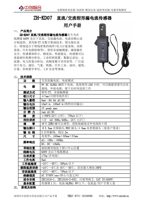
ZH-KD07直流/交流钳形漏电流传感器用户手册一.产品简介ZH-KD07直流/交流钳形漏电流传感器是专为在线测量600V 及以下直流、交流漏电流、电流而精心设计制造的,采用新CT 及数字集成技术,钳头细长设计,特别适合于排线密集的场所(电力计量系统、高铁系统、汽车电路检修等),钳形非接触测量,确保操作安全。
传感器体积小、精度高、性能稳定。
传感器可以连接相位检测分析仪、工业控制装置、数据记录仪、示波器、电力质量分析仪、高精度数字多用表等。
广泛适用于电力、通信、气象、铁路、汽车工业、油田、建筑、计量、科研教学单位、工矿企业等领域。
二.技术规格功能交直流漏电流、电流测试电源9V DC 6LR61碱性干电池,连续使用100小时,可以根据需要引出电源线,外接电源,便于长时间连续工作测试方式钳形CT,非接触测量钳口尺寸φ7mm(可钳导线外径)输入量程0mA~60.0A AC/DC 输出电压10mV/A;100mV/A(两档对应输出)输出范围1V peak max 分辨力1mA AC/DC 精度±3%FS(23℃±5℃,75%rh 以下)相位误差≤3°(AC 50Hz/60Hz;23℃±2℃)调零调节ZERO 键可以调零,消除地磁场及外电场的干扰输出接口φ3.5mm 音频插头/BNC 插头/4.0mm 双香蕉插头(按客户要求)输出线2芯屏蔽线,线长2m 尺寸高宽厚:168mm×65mm×34mm 频率响应AC:45Hz~400Hz DC:DC~10kHz 导线位置被检测导线处于钳口中心位置线路电压600V 及以下线路测试仪表质量170g(含电池)工作电流5mA 工作温湿度-10℃~50℃;80%rh 以下极限温度误差-10℃~0℃及40℃~50℃,误差最大增加2%FS 存放温湿度-10℃~60℃;70%rh 以下绝缘强度AC 3700V/rms(铁心与盒之间)适合安规IEC1010-1、IEC1010-2-032、污染等级2、CAT Ⅲ(600V)基本配置传感器1台、电池(6LR619V)1个、包装盒/用户手册1套三.原理及结构采用分割式铁芯和霍尔元件(hole element)组合,能同时检测交流和直流漏电流、电流,当被测电流I通过传感器时,霍尔元件感应输出一个霍尔电压V H,可以通过检测霍尔电压V H,来计算被测试电流I,霍尔电压V H比例于被测试电流I。
4-20mA输出电流传感器选型及报价
450
0-5V DC 信号
(有源剩余电流传感器)
注:1.型号后加“T”表示为真有效值测量; 2.模拟量输出有 0-5V、4-20mA、0-20mA 可选; 3.辅助电源有 12Vdc、24Vdc 两种; 4.BA 系列电流传感器为 35mm 导轨或螺钉安装。 联系方式:刘丹玲,女,本科,安科瑞电气股份有限公司,主要研究方向为智能电网供配电,手机: 18860995105 QQ:2880157879
TS35 导轨,或用螺钉固定柜体上
4 产品规格
4.1 BA05-AI 交流电流传感器
BA05-AI/I(V) 单相交流电流传感器(平均值法测量)
BA05-AI/I(V)-T 单相交流电流传感器(真有效值法测量)
技术参数 精度等级
标称值 过载 输入 吸收功率 频响 标称值 输出 负载电阻 响应时间
指标 0.5 级、0.2 级 电流 AC 0.5A、5A、10A 等 AC0~(0.5~10A) 持续 1.2 倍,瞬时电流 10 倍/5 秒
技术参数 精度等级
标称值 过载 输入 吸收功率 频响 标称值 输出 负载电阻 响应时间
指标 0.5 级、0.2 级 电流 AC 60A、300A 、600A 等 AC 0~(60~600)A 持续 1.2 倍,瞬时电流 10 倍/1S
≤1VA 25Hz~800Hz(平均值),25~5kHz(真有效值),特别适合工频场合
DC4~20mA,或 0~20mA,0~5V,0~10V 等 电流输出时≤500Ω,电压输出时≥1KΩ 平均值≤350ms,真有效值≤100ms
5 外形及安装
5.1 BA05-AI 交流电流传感器
5.2 BA10-AI 交流电流传感器
5.3 BA20-AI 交流电流传感器 5.4 BA50-AI 交流电流传感器
BA00508CZH Indumax CLS54D 电感式电导率传感器操作手册
8 9
9.1 9.2 9.3 9.4 9.5
返回 . . . . . . . . . . . . . . . . . . . . 17 技术参数 . . . . . . . . . . . . . . . . 18
导电性管道
绝缘管道
Endress+Hauser
9
安装
Indumax CLS54D
3.2
安装指南
a0018174
图 4: 传感器的安装位置示意图 1 a 介质流向 传感器与管壁间的距离
安装传感器,使得传感器开孔的方向与介质流向一致。传感器必须完全浸入在介质中。 空标 传感器已经通过出厂标定,无需现场补偿。
! 危险 原因 (/ 后续动作 ) 疏略安全信息的后续动作 • 校正动作 ! 警告 原因 (/ 后续动作 ) 疏略安全信息的后续动作 • 校正动作
说明 危险状况警示。 疏忽会导致人员死亡或严重伤害。
危险状况警示。 疏忽可能导致人员死亡或严重伤害。
小心 原因 (/ 后续动作 ) 疏略安全信息的后续动作 • 校正动作
索引 . . . . . . . . . . . . . . . . . . . . 22
Endress+Hauser
安全指南
Indumax CLS54D
1
1.1
• • • • •
安全指南
人员要求
仅允许经培训的专业技术人员进行测量系统的安装、调试、操作和维护。 执行特定操作的技术人员必须经工厂厂方授权。 仅允许电工进行设备的电气连接。 技术人员必须阅读 《操作手册》 ,理解并遵守其中的各项规定。 仅允许经专业培训的授权人员进行测量点故障排除。 仅允许制造商或其服务机构直接进行 《操作手册》中未描述的维修操作。
负压电流传感器说明说明书

SPECIFICATIONSGENERALMaximum Pressure:10 psig (0.7kg/cm).Media Compatibility:Air and non-conduction, non-corrosive gases.ELECTRICAL Power Supply:12-36 VDC, unregulated.Output Signal:4-20 mA DC, two wire.Loop Resistance:0-1090 ohmsV min.= 12V + [(.022A)(R L )]Warm-up Time:15 seconds.PERFORMANCE AT 70°F .Output at zero: 4 mA.Output at full span:20 mA.Stability:±0.5% of full span/year.Response Time:250 msec.TEMPERATURE LIMITS Operating:-20 to 160°F (-29 to 71°C), 10-95% RH, pensated:35 to 135°F (2 to 57°C).Storage:-40 to 180°F (-40 to 82°F).Thermal Effects:±0.015%F .S./°F (zero and span).MECHANICAL Housing:300 Series stainless steel (NEMA 2).Pressure Connections:4″barbed stainless steel. Weight:14 oz (397 g).Span and Zero:Factory set to specified range.Externally accessible, non-interactive, ±10% F .S. adjustment.BULLETIN E-76SERIES 607 DIFFERENTIAL PRESSURE TRANSMITTER Specifications– Installation and Operating Instructions3.312 [84.12]3.924 [99.67]4.564 [115.93]1.652[41.96].210 [5.33]3.405[86.49] 3.875[98.43]4.195[106.55]1.825 [46.36]1.290 [32.77]DescriptionThe Dwyer Series 607 Differential Pressure Transmitter converts positive, negative (vacuum) or differential pressures of clean, dry air or other non-conductive, non-corrosive gases into a standard two wire, 4-20 mA output signal. Several factory calibrated models are available with ranges from 0-.10″W.C. to 0-25″W.C. All models employ a variable capacitance transducer with a micro-machined, ultra thin silicon diaphragm enabling precision measurement and control of very low pres-sures. Because no epoxies or other organics are used to seal the sensor, performance is exceptionally stable and drift free.It is also highly resistant to overpressure, shock and vibration.See specifications for complete details.Model Range Number in w.c.607-00-.10607-10-.25607-20-.50607-30-1.0607-40-2.0607-70-5.0607-80-10Model Range Number in w.c.607-90-25607-0B .10-0-.10607-1B .25-0-.25607-2B .50-0-.50607-3B 1.0-0-1.0607-4B 2.0-0-2.0607-7B5.0-0-5.0Model Range Number in w.c.607-010-.10607-110-.25Model Range Number in w.c.607-210-.50607-710-5.0SERIES 607 TRANSMITTER MODELS & RANGESAccuracy ±0.5% of Full Scale *Accuracy ±0.25% of Full Scale ** Includes Linearity, Hysteresis, and RepeatabilityFIGURE ACalibrationEach Series 607 Transmitter is factory calibrated to the range listed in the model number chart. Range is defined as that pressure which when applied to the transmitter will produce a 20 milliamp current in the loop. Zero pressure will produce 4milliamps. If fine adjustment of calibration is required, used the following procedure:1).With the transmitter connected to its’ companion receiver,insert a milliammeter in series with the current loop. A controllable pressure source should be teed to the high pressure port of the transmitter and to an accurate pres-sure gage or manometer.2).Apply electrical power to the system and allow 15seconds form components to stabilize.3).With no pressure applied to the transmitter removeblowout disc and adjust “zero” control so loop current is 4mA.4).Apply full span pressure and adjust loop current to 20 mAusing “span” control.5).Remove the milliammeter from the circuit, replace blowoutdisc, and place system in service. Maintenance/RepairAfter final installation of the Series 607 Differential Pressure Transmitter, no routine maintenance is required. A periodic check of system calibration is recommended. These devices are not field repairable and should be returned to the factory if recalibration or other service is required. After first obtaining a Returned Goods Authorization (RGA) number, send the mater-ial, freight prepaid, to the following address. Please include a clear description of the problem plus any application informa-tion available.Dwyer Instruments, Inc.Attn: Repair Department 102 Highway 212Michigan City, IN 46360©Copyright 1999 Dwyer instruments, Inc Printed in U.S.A. 2/99FR 01-440685-00Installation1. Location: Select a clean, dry location free of excess vibra-tion where the temperature of the unit with be between -20 and 160°F . Distance from the receiver is limited only by total loop resistance. See “ Electrical Connections”. The tubing supply-ing pressure to the transmitter can be run practically any distance. Long tubing lengths will not affect accuracy but response time will be increased slightly.2. Position: The Series 607 Transmitter is not position sensi-tive. However, it is recommended that you avoid mounting with pressure connections pointing up because of the chance of condensed moisture entering the interior. Moisture can also be avoided by routing tubing with a low point just ahead of the transmitter.3. Mounting: Attach to mounting surface with two #8 or #10screws in the mounting slots provided.4. Pressure connections: The Series 607 Transmitter is shipped with a short length of tubing installed between the ports to keep the interior clean. Remove it and discard after unit is mounted. Connect positive (above atmospheric) pres-sure to port marked “HIGH and vent the “LOW” port. Connect negative (vacuum) pressure to port marked “LOW” and vent the “HIGH” port. For differential pressures, connect the higher one to the “HIGH” port and the lower one to the “LOW” port. Electrical ConnectionCaution: Do not exceed the specified supply voltage rating.Permanent damage, not covered by warranty, may result. This unit is not designed for AC voltage operation.Electrical connections to the Series 607 Transmitter are made to the two screws on the terminal strip labeled + and -. If polar-ity is inadvertently reversed, the loop will not function properly but no damage will be done to the transmitter because of inter-nal circuit protection. An external power supply delivering 12to 36 VDC must be used to power the control loop in which the transmitter is connected. Refer to Figure B for connection of the power supply, transmitter and receiver. The power required to generate the 4-20 mA output signal depends on the loop resistance of the circuit and is proportional to the resistance according to the graph and formula in Figure C. The maximum length that can be used in the current loop is a function of wire size and receiver resistance. A shielded two conductor cable is recommended for control loop wiring. Make sure the total loop resistance is within the operating region as shown in Figure C.GROUND OPTIONALRECEIVER (R L )SERIES 607PRESSURE TRANS- MITTERSEE FIG. C+_+_POWER SUPPLY 12-36 VDCNOTE: RECEIVER MAY BE IN SERIES WITH + OR - LEG OF CONTROL LOOP510122025303640010020030040050060070080090010001100POWER SUPPLY VOLTAGE - VDCL O O P R E S I S T A N C E (Ω)V MIN = 12V + (.022A x R L )OPERATING RANGEMAXIMUM VALUE (1090)FIGURE BFIGURE C。
爱乐高ACS706ELC-05C双向1.5mΩ霍尔效应线性电流传感器IC电路使用手册说明书

NOTE: For detailed information on purchasing options, contact your local Allegro field applications engineer or sales representative.Allegro MicroSystems, Inc. reserves the right to make, from time to time, revisions to the anticipated product life cycle plan for a product to accommodate changes in production capabilities, alternative product availabilities, or market demand. The information included herein is believed to be accurate and reliable. However, Allegro MicroSystems, Inc. assumes no respon-sibility for its use; nor for any infringements of patents or other rights of third parties which may result from its use.Recommended Substitutions:For existing customer transition, and for new customers or new appli-cations, refer to the ACS712.Bidirectional 1.5 mΩ Hall Effect Based Linear Current Sensor ICwith V oltage Isolation and 15 A Dynamic RangeACS706ELC-05CDate of status change: December 26, 2006These parts are in production but have been determined to beNOT FOR NEW DESIGN. This classification indicates that sale of this device is currently restricted to existing customer applications. The device should not be purchased for new design applications because obsolescence in the near future is probable. Samples are no longer available.Not for New DesignFeatures and Benefits• Small footprint, low-profile SOIC8 package• 1.5 m Ω internal conductor resistance• 1600 V RMS minimum isolation voltage between pins 1-4 and 5-8• 4.5 to 5.5 V, single supply operation • 50 kHz bandwidth• 133 mV/A output sensitivity and 15 A dynamic range • Output voltage proportional to ac and dc currents • Factory-trimmed for accuracy• Extremely stable output offset voltage • Near-zero magnetic hysteresis• Ratiometric output from supply voltageThe Allegro ACS706 family of current sensor ICs provides economical and precise solutions for current sensing in industrial, automotive, commercial, and communications systems. The device package allows for easy implementation by the customer. Typical applications include motor control, load detection and management, switch-mode power supplies, and overcurrent fault protection.The device consists of a precision, low-offset linear Hall circuit with a copper conduction path located near the surface of the die. Applied current flowing through this copper conduction path generates a magnetic field which the Hall IC converts into a proportional voltage. Device accuracy is optimized through the close proximity of the magnetic signal to the Hall transducer. A precise, proportional voltage is provided by the low-offset, chopper-stabilized BiCMOS Hall IC, which is programmed for accuracy at the factory.The output of the device has a positive slope (>V CC / 2) when an increasing current flows through the primary copper conduction path (from pins 1 and 2, to pins 3 and 4), which is the path used for current sampling. The internal resistance of this conductive path is typically 1.5 m Ω, providing low power loss. The thickness of the copper conductor allows survival of the device at up to 5× overcurrent conditions. The terminals of the conductive path are electrically isolated from the signal leads (pins 5 through 8). This allows the ACS706 to be used in applications requiring electrical isolation without the use of opto-isolators or other costly isolation techniques.The ACS706 is provided in a small, surface mount SOIC8 package. The leadframe is plated with 100% matte tin, which is compatible with standard lead (Pb) free printed circuit board assembly processes. Internally, the flip-chip uses high-temperature Pb-based solder balls, currently exempt from RoHS. The device is fully calibrated prior to shipment from the factory.Use the following complete part number when ordering:Part NumberPackageACS706ELC-05CSOIC8 surface mountTÜV AmericaCertificate Number:U8V 04 12 54214 005AB S O L UTE MAX I M UM RAT I NGSSupply V oltage, V CC ..........................................16 V Reverse Supply V oltage, V RCC ........................–16 V Output V oltage, V OUT ........................................16 V Reverse Output V oltage, V ROUT ......................–0.1 V Output Current Source, I OUT(Source) ................. 3 mA Output Current Sink, I OUT(Sink) .......................10 mA Maximum Transient Sensed Current *, I R(max) ...100 A Operating Temperature, Maximum Junction, T J(max).......................165°C Storage Temperature, T S ......................–65 to 170°C*Junction Temperature, T J < TJ(max).*100 total pulses, 250 ms duration each, applied at a rate of1 pulse every 100 seconds.Nominal Operating Temperature, T A Range E ............................................–40 to 85ºC Overcurrent Transient Tolerance*, I P ................60 ABidirectional 1.5 m Ω Hall Effect Based Linear Current Sensorwith Voltage Isolation and 15 A Dynamic RangePackage LCPin 1: IP+Pin 2: IP+Pin 3: IP–Pin 4: IP–Pin 8: VCC Pin 7: VOUTPin 6: N.C.Pin 5: GNDPins 6 and 7 are internally connected in shipping product. For compatibility with future devices, leave pin 6 floating.Functional Block Diagram0.1 μFPERFORMANCE CHARACTERISTICS, over operating ambient temperature range, unless otherwise specifiedPropagation Time t PROP I P =±5 A, T A = 25°C– 3.15–μs Response Time t RESPONSE I P =±5 A, T A = 25°C–6–μs Rise Time t r I P =±5 A, T A = 25°C–7.45–μs Frequency Bandwidth f–3 dB, T A = 25°C; I P is 10 A peak-to-peak; no external filter–50–kHzSensitivity Sens Over full range of I P , I P applied for 5 ms; T A = 25°C–133–mV/A Over full range of I P , I P applied for 5 ms124–142mV/ANoise V NOISE Peak-to-peak, T A = 25°C, no external filter–90–mV Root Mean Square, T A = 25°C, no external filter–16–mVLinearity E LIN Over full range of I P , I P applied for 5 ms–±1±4.7% Symmetry E SYM Over full range of I P , I P applied for 5 ms98100104.5% Zero Current Output Voltage V OUT(Q)I P = 0 A, T A = 25°C–V CC / 2–VElectrical Offset Voltage V OE I P = 0 A, T A = 25°C–15–15mV I P = 0 A–65–65mVMagnetic Offset Error I ERROM I P = 0 A, after excursion of 5 A–±0.01±0.05ATotal Output Error1E TOT I P =±5 A, I P applied for 5 ms;T A = 25°C–±1.5–% I P = ±5 A, I P applied for 5 ms––±12.5%Characteristic Symbol Test Conditions Min.Typ.Max.Units ELECTRICAL CHARACTERISTICS, over operating ambient temperature range unless otherwise specifiedOptimized Accuracy Range I P–5–5A Linear Sensing Range I R–15–15A Supply Voltage V CC 4.5 5.0 5.5V Supply Current I CC V CC = 5.0 V, output open5810mA Output Resistance R OUT I OUT = 1.2 mA–12ΩOutput Capacitance Load C LOAD VOUT to GND––10nF Output Resistive Load R LOAD VOUT to GND 4.7––kΩPrimary Conductor Resistance R PRIMARY T A = 25°C– 1.5–mΩRMS Isolation Voltage V ISORMS Pins 1-4 and 5-8; 60 Hz, 1 minute16002500–V DC Isolation Voltage V ISODC–5000–V OPERATING CHARACTERISTICSTHERMAL CHARACTERISTICS2,3, T A = –40°C to 125°C, V CC = 5 V unless otherwise specified–Value–UnitsJunction-to-Lead Thermal Resistance RθJLMounted on the Allegro ASEK 70x evaluation board; additionalinformation about reference boards and tests is available on theAllegro Web site–5–°C/WJunction-to-Ambient Thermal Resistance RθJAMounted on the Allegro ASEK 70x evaluation board; additionalinformation about reference boards and tests is available on theAllegro Web site–41–°C/W1Percentage of I P, with I P = 5 A. Output filtered. Up to a 2.0% shift in E TOT may be observed at end-of-life for this device.2 The Allegro evaluation board has 1500 mm2 of 2 oz. copper on each side, connected to pins 1 and 2, and to pins3 and 4, with thermal vias connect-ing the layers. Performance values include the power consumed by the PWB. Further details on the board are available from the ACS704 Frequently Asked Questions document on our website. Further information about board design and thermal performance also can be found on pages 16 and 17 of this datasheet.3RθJA values shown in this table are typical values, measured on the Allegro evaluation board. The actual thermal performance depends on the board design, the airflow in the system, and thermal interactions between the device and surrounding components through the PCB and the ambient air. To improve thermal performance, see our applications material on the Allegro Web site.Typical Performance Characteristics-50-25255075100125150Supply Current versus Ambient TemperatureV CC = 5 VT A (°C)I C C (m A )4.54.64.74.84.95 5.15.25.35.45.5V CC (V)I C C (m A )8.008.058.108.158.208.258.308.358.408.458.50Supply Current versus Applied VCC11.01.52.02.53.03.54.0-9-8-7-6-5-4-3-2-10123456789V O U T (V )Output Voltage versus Primary CurrentV CC = 5 VI P (A)110115120125130135140145150160S e n s (m V /A )-9-8-7-6-5-4-3-2-1123456789I P (A)Sensitivity versus Primary CurrentV CC = 5 V-50-250255075100125150V O U T (Q ) (V )2.4702.5802.4902.5002.5102.5202.530Zero Current Output Voltage vs. Ambient TemperatureT A (°C)I P = 0 AZero Current Output Currrent versus Ambient Temperature(Data in above chart converted to amperes)I V O U T (Q ) (A )–0.3–0.2–0.10.10.20.3–50–25255075100125150T A (°C)V O M (m A )-1.0-0.8-0.6-0.4-0.200.20.40.60.81.0-50-25255075150100125T A (°C)Magnetic Offset Error versus Ambient TemperatureV CC = 5 V; I P= 0 A, after excursion to 5 A-50-25255075150100125T A (°C)00.51.01.52.02.53.0E L I N (%)Nonlinearity versus Ambient TemperatureV CC = 5 V I P= 5 ATypical Peak-to-Peak Noise of ACS706ELC-05C at T A =25°CStep Response of ACS706ELC-05C at T A =25°CACS706 Output (mV)5 A Excitation SignalTime = 10 μs/div.Excitation signal = 1.00 A/div.Output = 100 mV/div.Time = 20 μs/div.Noise = 20.0 mV/div.ACS706ELC-05C Noise Filtering and Frequency Response Performance Break Frequencyof Filter on Output(kHz)Resistance,R F (kΩ)Capacitance,C F (μF)NominalProgrammedSensitivity(mV/A)FilteredPeak-to-Peak Noise(mV)Resolutionwith Filtering(A)Rise Timefor 5A Step,Filtered(μs)Unfiltered––133 900.6777.45800.2000.01 75.90.5718.26500.32064.70.48610.08 400.39260.30.45311.39 200.80043.30.32617.56 10 1.628.90.21831.96 7.0 3.1518.30.13754.55 3.3 4.813.80.10481.77 0.626 1.90.015404.16 0.3530.760.00573732.89OUTTypical Application DrawingThe ACS706 outputs an analog signal, V Sig. that varies linearly with the bidirectional primarysensed current, I P, within the range specified. R F and C F, are recommended for noise management,with values that depend on the application, as shown in the noise filtering table.Sensitivity (Sens). The change in device output in response to a 1 A change through the primary conductor. The sensitivity is the prod-uct of the magnetic circuit sensitivity (G / A ) and the linear IC amplifier gain (mV/G). The linear IC amplifier gain is programmed at the factory to optimize the sensitivity (mV/A) for the full-scale current of the device.Noise (V NOISE ). The product of the linear IC amplifier gain (mV/G) and the noise floor for the Allegro Hall effect linear IC (≈1 G). The noise floor is derived from the thermal and shot noise observed in Hall elements. Dividing the noise (mV) by the sensitivity (mV/A) provides the smallest current that the device is able to resolve.Linearity (E LIN ): The degree to which the voltage output from the device varies in direct proportion to the primary current through its full-scale amplitude. Nonlinearity in the output can be attributed to the saturation of the flux concentrator approaching the full-scale current. The following equation is used to derive the linearity:Definitions of Accuracy Characteristics1001– [{[{V out_full-scale amperes –V OUT(Q)()2 (V out_half-scale amperes –V OUT(Q))100where V out_full-scale amperes = the output voltage (V) when the sensed current approximates full-scale ±I P .Symmetry (E SYM ). The degree to which the absolute voltage output from the device varies in proportion to either a positive or nega-tive full-scale primary current. The following formula is used to derive symmetry:Quiescent output voltage (V OUT(Q)). The output of the device when the primary current is zero. For a unipolar supply voltage, it nominally remains at V CC ⁄ 2. Thus, V CC = 5 V translates into V OUT(Q) = 2.5 V . Variation in V OUT(Q) can be attributed to the resolution of the Allegro linear IC quiescent voltage trim and thermal drift.Electrical offset voltage (V OE ). The deviation of the device output from its ideal quiescent value of V CC / 2 due to nonmagnetic causes. To convert this voltage to amperes, divide by the device sensitivity, Sens.Accuracy (E TOT ). The accuracy represents the maximum deviation of the actual output from its ideal value. This is also known as the total ouput error. The accuracy is illustrated graphically in the Output V oltage versus Current chart on the following page.Accuracy is divided into four areas:∙ 0 A at 25°C. Accuracy at zero current flow at 25°C, without the effects of temperature.∙ 0 A over Δ temperature. Accuracy at zero current flow including temperature effects.∙ Full-scale current at 25°C. Accuracy at the full-scale current at 25°C, without the effects of temperature.∙ Full-scale current over Δ temperature. Accuracy at full-scale current flow including temperature effects.Ratiometry . The ratiometric feature means that its 0 A output, V OUT(Q), (nominally equal to V CC /2) and sensitivity, Sens, are propor-tional to its supply voltage, V CC . The following formula is used to derive the ratiometric change in 0 A output voltage, ∆V OUT(Q)RAT (%):100V IOUT(Q)VCC /V IOUT(Q)5VV CC /5 VThe ratiometric change in sensitivity, ∆Sens RAT (%), is defined as:100Sens VCC /Sens 5V V CC /5 V ‰Output voltage vs. current, illustrating device accuracy at 0 A and at full-scale currentDefinitions of Dynamic Response CharacteristicsPropagation delay (t PROP): The time required for the device output to reflect a change in the primary cur-rent signal. Propagation delay is attributed to inductive loading within the linear IC package, as well as in the inductive loop formed by the primary conductor geometry. Propagation delay can be considered as a fixed time offset and may be compensated.Response time (t RESPONSE): The time interval between a) when the primary current signal reaches 90% of its final value, and b) when the device reaches 90% of its output corresponding to the applied current.Rise time (t r): The time interval between a) when the device reaches 10% of its full scale value, and b) when it reaches 90% of its full scale value. The rise time to a step response is used to derive the bandwidth of the device, in which ƒ(–3 dB) = 0.35 / t r. Both t r and t RESPONSE are detrimentally affected by eddy current losses observed in the conductive IC ground plane.Device Branding Key (Two alternative styles are used)ACS706T ELC05C YYWWA ACS Allegro Current Sensor706Device family numberT Indicator of 100% matte tin leadframe platingE Operating ambient temperature range codeLC Package type designator05C Primary sensed currentYY Manufacturing date code: Calendar year (last two digits) WW Manufacturing date code: Calendar weekA Manufacturing date code: Shift codeACS706T ELC05CL...L YYWWACS Allegro Current Sensor706Device family numberT Indicator of 100% matte tin leadframe platingE Operating ambient temperature range codeLC Package type designator05C Primary sensed currentL...L Manufacturing lot codeYY Manufacturing date code: Calendar year (last two digits)WW Manufacturing date code: Calendar week Standards and Physical SpecificationsParameter SpecificationFlammability (package molding compound)UL recognized to UL 94V-0Fire and Electric Shock UL60950-1:2003EN60950-1:2001CAN/CSA C22.2 No. 60950-1:2003Chopper Stabilization TechniqueChopper Stabilization is an innovative circuit technique that is used to minimize the offset voltage of a Hall element and an associated on-chip amplifier. Allegro patented a Chopper Stabilization technique that nearly eliminates Hall IC output drift induced by temperature or package stress effects. This offset reduction technique is based on a signal modulation-demodulation process. Modulation is used to separate the undesired dc offset signal from the magnetically induced signal in the frequency domain. Then, using a low-pass filter, the modu-lated dc offset is suppressed while the magnetically induced signal passes through the filter. As a result of this chopper stabilization approach, the output voltage from the Hall IC is desensitized to the effects of temperature and mechanical stress. This technique produces devices that have an extremely stable Electrical Offset V oltage, are immune to thermal stress, and have precise recoverability after temperature cycling.This technique is made possible through the use of a BiCMOS process that allows the use of low-offset and low-noise amplifiers in combination with high-density logic integration and sample and hold circuits.Concept of Chopper Stabilization TechniqueApplications InformationIn order to quantify transient common-mode voltage rejection for the ACS706, a device was soldered onto a printedcircuit board. A 0.1 μF bypass capacitor and a 5 V dc power supply were connected between VCC and GND (pins 8 and5) for this device. A 10 k Ω load resistor and a 0.01 μF capacitor were connected in parallel between the VOUT pin andthe GND pin of the device (pins 7 and 5).A function generator was connected between the primary current conductor (pins 1 thru 4) and the GND pin ofthe device (pin 5). This function generator was configured to generate a 10 V peak (20 V peak-to-peak) sinewave between pins 1-4 and pin 5. Note that the sinusoidal stimulus was applied such that no electrical currentwould flow through the copper conductor composed of pins 1-4 of this device.The frequency of this sine wave was varied from 60 Hz to 5 MHz in discrete steps. At each frequency, thestatistics feature of an oscilloscope was used to measure the voltage variations (noise) on the ACS706 outputin mV (peak to peak). The noise was measured both before and after the application of the stimulus. Transientcommon-mode voltage rejection as a function of frequency is shown in the following figure.Transient Common-Mode Voltage Rejection in the ACS706(kHz)Frequency of 20 V Peak-to-Peak Stimulus –60–55–50–45–40–35–30Tr a nsi e ntR ej ect i o n(d B)The Effect of PCB Layout on ACS706 Thermal PerformanceEight different PC boards were fabricated to characterize the effect of PCB design on the operating junction temperature of the Hall-effect IC inside of the ACS706. These PC boards are shown in the figure below. 2 oz. Cu on one side of board 2 oz. Cu on both sides of board An ACS706 device was soldered on to each PCB for thermal testing. The results of the testing are shown in the following table.Test Results on Eight Thermal Characterization PCBsTested at 15A, T A = 20°C, still air, 2 oz. copper traces, current carried on and off boardby 14 gauge wiresPC BoardsSides with Traces Trace Width (mm)Trace Length (mm)Temperature Rise Above Ambient (°C)1 450901.550Overheated 410481.5101102450531.550106410381.51054Improved PC Board DesignsThe eight PC boards in the figure above do not represent an ideal PC board for use with the ACS706. The ACS706 evaluation boards, for sale at the Allegro Web site On-Line Store, represent a more optimal PC board design (see photo below). On the evaluation boards, the current to be sensed flows through very wide traces that were fabricated using 2 layers of 2 oz. copper. Thermal management tests were conducted on the Allegro evaluation boards and all tests were performed using the same test conditions described in the bulleted list above. The results for these thermal tests are shown in the table below. When using the Allegro evaluation boards we see that even at an applied current of 20 A the junction temperature of the ACS706 is only ≈30 degrees above ambient temperature.Test Results on Eight Electrical Characterization PCBsTested at T A = 20°C, still airApplied Current(A)Temp Rise Above Ambient( C)1522 2031Allegro Current sensor IC evaluation board with ACS706 and external connections.The products described herein are manufactured under one or more of the following U.S. patents: 5,045,920; 5,264,783; 5,442,283; 5,389,889; 5,581,179; 5,517,112; 5,619,137; 5,621,319; 5,650,719; 5,686,894; 5,694,038; 5,729,130; 5,917,320; and other patents pending.Allegro MicroSystems, Inc. reserves the right to make, from time to time, such de p ar t ures from the detail spec i f i c a t ions as may be required topermit improvements in the per f or m ance, reliability, or manufacturability of its products. Before placing an order, the user is cautioned to verify that the information being relied upon is current.Allegro products are not authorized for use as critical components in life-support devices or sys t ems without express written approval.The in f or m a t ion in c lud e d herein is believed to be ac c u r ate and reliable. How e v e r, Allegro MicroSystems, Inc. assumes no re s pon s i b il i t y for its use; nor for any in f ringe m ent of patents or other rights of third parties which may result from its use.Copyright©2005, 2006 Allegro MicroSystems, Inc.Package LC, 8-pin SOICPreliminary dimensions, for reference onlyDimensions in millimetersU.S. Customary dimensions (in.) in brackets, for reference only(reference JEDEC MS-012 AA)Dimensions exclusive of mold flash, gate burrs, and dambar protrusionsExact case and lead configuration at supplier discretion within limits shownA Terminal #1 mark area。
电流传感器六角汇流排套件安装指南说明书
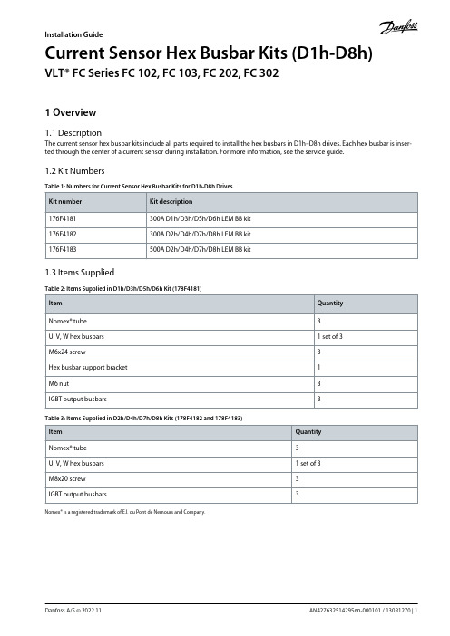
The current sensor hex busbar kits include all parts required to install the hex busbars in D1h–D8h drives. Each hex busbar is inser-ted through the center of a current sensor during installation. For more information, see the service guide.1.2 Kit NumbersTable 1: Numbers for Current Sensor Hex Busbar Kits for D1h-D8h Drives1.3 Items SuppliedTable 2: Items Supplied in D1h/D3h/D5h/D6h Kit (178F4181)Table 3: Items Supplied in D2h/D4h/D7h/D8h Kits (178F4182 and 178F4183)Nomex® is a registered trademark of E.I. du Pont de Nemours and Company.AN427632514295en-000101 / 130R1270 | 1Danfoss A/S © 2022.11Installation GuideCurrent Sensor Hex Busbar Kits (D1h-D8h)VLT® FC Series FC 102, FC 103, FC 202, FC 3021 Overvie w1.1 Description1.4 Hex Busbar Identificatione 30b k 388.1Table 4: Hex Busbar ComparisonAN427632514295en-000101 / 130R12702 | Danfoss A/S © 2022.11OverviewCurrent Sensor Hex Busbar Kits (D1h-D8h)Installation Guide2 Installation2.1 Safety InformationAN427632514295en-000101 / 130R1270 | 3Danfoss A/S © 2022.11InstallationCurrent Sensor Hex Busbar Kits (D1h-D8h)Installation Guide1.2.3.4.5.6.2.2 Assembling the Current Sensor Hex Busbars in D1h/D3h/D5h/D6h DrivesUse the following steps to assemble the current sensor hex busbars in D1h/D3h/D5h/D6h drives. See Illustration 1.ProcedureReplace the existing IGBT output busbars with the 3 IGBT output busbars from the kit, and fasten the busbars to the IGBTmodules.Fasten 3 M6x24 screws (T30) through the motor busbars and into the threads of the 3 hex busbars, 1 per busbar.AN427632514295en-000101 / 130R12704 | Danfoss A/S © 2022.11InstallationCurrent Sensor Hex Busbar Kits (D1h-D8h)Installation Guidee 30b K 389.1056734218Illustration 1: Current Sensor Hex Busbar Assembly (D1h/D3h/D5h/D6h Drives)1IGBT output busbar 2Hex busbar support bracket 3M6 nut 4Current sensor (1)5Hex busbar 6Nomex® tube 7Motor busbar (1)8M6x24 screw1Current sensors and motor busbars are not included in kit 176F4181.AN427632514295en-000101 / 130R1270 | 5Danfoss A/S © 2022.11InstallationCurrent Sensor Hex Busbar Kits (D1h-D8h)Installation Guide1.2.3.4.5.2.3 Assembling the Current Sensor Hex Busbars in D2h/D4h/D7h/D8h DrivesUse the following steps to assemble the current sensor hex busbars in D2h/D4h/D7h/D8h drives. See Illustration 2.ProcedureReplace the existing IGBT output busbars with the 3 IGBT output busbars from the kit, and fasten the busbars to the IGBTmodules.Fasten 3 M8x20 screws (T40) through the motor busbars and into the threads of the 3 hex busbars, 1 per busbar.AN427632514295en-000101 / 130R12706 | Danfoss A/S © 2022.11InstallationCurrent Sensor Hex Busbar Kits (D1h-D8h)Installation Guidee 30b K 390.10362541Illustration 2: Current Sensor Hex Busbar Assembly (D2h/D4h/D7h/D8h Drives)1IGBT output busbar 2Current sensor (1)3Nomex® tube4Hex busbar 5Motor busbar (1)6M8x20 screw1Current sensors and motor busbars are not included in kits 176F4182 and 176F4183.AN427632514295en-000101 / 130R1270 | 7Danfoss A/S © 2022.11InstallationCurrent Sensor Hex Busbar Kits (D1h-D8h)Installation GuideAN427632514295en-000101 / 130R12708 | Danfoss A/S © 2022.11InstallationCurrent Sensor Hex Busbar Kits (D1h-D8h)Installation GuideDanfoss A/S Ulsnaes 1DK-6300 Graasten Danfoss can accept no responsibility for possible errors in catalogs, brochures, and other printed material. Danfoss reserves the right to alter its products without notice.This also applies to products already on order provided that such alterations can be made without subsequential changes being necessary in specifications already agreed. All trademarks in this material are property of the respective companies. Danfoss and the Danfoss logotype are trademarks of Danfoss A/S. All rights reserved.*130R1270*01。
帕德赫德PDHD-503型剩余电流式电气火灾监控探测器说明书

PDHD-503剩余电流式电气火灾监控探测器使用说明书(1-12路漏电)帕德赫德电气技术(深圳)有限公司网址:全国服务热线:400-803-0813本产品为智能型电子消防产品,使用前请详细阅读本说明书,并在使用前做通电测试。
如需要技术支持,请拨本公司售后服务热线电话获得技术支持,本产品如有技术升级,恕不另行通知。
目录一.概述 (1)二.使用范围 (1)三.使用条件和产品功能 (1)四.工作状态及设置说明 (2)五.安装说明 (7)六.注意事项 (9)七.两种不同接地方式的剩余电流监控保护系统应用 (9)八.存贮和运输 (10)九.售后服务 (10)概述PDHD-503本产品是一种智能型剩余电流式火灾监控探测器,它采用32位微型控制器、可全天候有效地监控被保护电气线路中由于漏电可能发生的火灾隐患,实时处理当前剩余电流值,将监测到的异常参数通过CAN总线通讯网络发送到监控中心。
同时发出声光报警信号,及时提醒工作人员检查故障,排除可能发生的电气隐患,防止重大事故的发生。
PDHD-503本产品实时监控度高、可靠性强,具有小型化、集成度高、功能齐全、简单实用、安装方便等特点。
本机采用1路4位数码管显示,亮度高,适合安装在恶劣的工作环境下。
二.使用范围PDHD-503剩余电流式火灾监控探测器依据GB14287.2—2014《电气火灾监控系统第二部分:剩余电流式电气火灾监控探测器》而设计,并符合本标准要求。
可广泛应用于工厂、学校、大型库房、办公室、商业建筑、宾馆、民用住宅及综合娱乐场所等电气火灾发生几率大、电气线路复杂的变电系统中。
但本产品不适用于易燃易爆和强腐蚀性环境。
剩余电流式电气火灾监控探测器,即可以为保护相对独立的用电区域而单独安装,也可以联网组成电气火灾监控报警系统。
三.使用条件和产品功能1、本产品的正常使用条件环境温度:-10℃—+50℃,24小时平均温度不超过35℃;相对湿度:10%—95%;海拔高度:小于4000米;污染等级:Ip3,无霜雪雨水侵蚀;2、主要技术参数额定工作电压:Ac220V50HZ;最大功耗:5W;报警输出:无源开关(俗称触点),触点最大容量220V5A;报警光讯号:红色LED;故障光讯号:黄色LED;报警声讯号:72db—115db;报警设定值:300mA—1000mA连续可调,最小可调1mA;漏电报警误差:设定值的80%—100%;四.工作状态及设置说明剩余电流式电气火灾监控探测器正常运行时无需人工干预。
穿孔式交流电流传感器选型
交流电流传感器选型
安科瑞王长幸
1BA系列交流电流传感器概述
BA系列产品应用电磁感应原理,对电网中的交流电流进行实时测量,采用精密恒流技术和线性温度补偿技术,将其隔离变换为标准的直流信号输出。
采用24伏或12伏安全电压供电,具有过载能力强、高精度、高隔离、高安全性、低功耗等特点,可广泛用于工业自动化领域。
BA系列中剩余电流传感器专用于漏电监控,监测电气线路或电气设备绝缘状态,避免电气线路或电气设备绝缘性能降低引起的事故。
产品符合GB/T13850-1998、GB1208-2006T0510-********
2BA系列交流电流传感器型号说明
3BA系列交流电流传感器技术指标
4BA系列交流电流传感器外形及穿孔尺寸BA05电流传感器
BA10电流传感器
BA20电流传感器
BA50电流传感器
BA50L剩余电流传感器
5BA系列交流电流传感器接线示例
如图一所示:穿心输出lac,
电流输出型(OUT:ldc)传感器的输出为共地电流源;电压输出型(OUT:Vdc)传感器的输出为共地电压源图中RL是用户负载,输出为电流时,负载≤400Ω;输出为电压时,负载为≥lkΩ
6BA系列交流电流传感器应用方案。
瑞必欧电流传感器说明书

Application Manual1800.888.5538 : Relay and Current Sensor in OneDirectly start/stop load and current sensing all in one package (no external ring is needed.) Wire colors to “Load” and “60 Hz ac” differ depending on the model being used. Configurations are either YELLOW & ORANGE, BLUE & YELLOW, or ORANGE & ORANGE.Internal 20 AmpRIBX24BF RIBX24SBF RIBX24BA RIBX24SBAInternal 10 AmpRIBXLCF RIBXLSF RIBXLCA RIBXLSAInternal 5 AmpRIBXLCEA RIBXLSEAMotor StarterAllows relay to control a motor starter while sensing current flowing to the motor.External Sensor RingRIBXLCRF RIBXLCRA RIBXLCJF RIBXLCJA RIBXLSRF RIBXLSRA RIBXLSJF RIBXLSJASensor only for 1.25 Amp to 150 Amp LoadUse sensor only devices without relay where start/stop is not required.External Sensor RingRIBXRA RIBXRFPanel Mounted Relay and Internal SensorStart/Stop Relays with Internal Current Sensors measure current flow through the relay contacts, no external ring is needed. Senses current as low as .50 Amp.Internal 20 AmpRIBMX24BFRIBMX24SBFRIBMX24BARIBMX24SBAInterlocking LoadsSome RIBX current sensor relays can be used to sense 1 or more loads to turn on another.Internal 10 AmpRIBXLCRFRIBXLCRARIBXLCJFRIBXLCJARIBXLSRFRIBXLSRARIBXLSJFRIBXLSJAInterlocking Loads (No Transformer)Self-powered Current Sensors of the RIBX Series and relays of the Dry Contact Input RIB® Series may be applied to interlock Load 2 to Load 1.Dry Contact Input RelaysRIB21CDCRIB01BDCRIB01SBDCRIB02BDCRIB02SBDCRIBM01ZNDCRIBM02ZNDCRIBM013PNDCRIBD01BDC (Time Delay)RIBD02BDC (Time Delay)RIBD01BDC-DOB (Time Delay)RIBD02BDC-DOB (Time Delay)Current SensorsRIBXKFRIBXKTFRIBXKARIBXKTARIBXGARIBXGFRIBXGTARIBXGTFRIBXGFLRIBXGTFLRIBXFRIBXARIBXRFRIBXRARIBXJFRIBXJARIBMXFRIBMXARIBMXRFRIBMXRA2Functional Devices, Inc. : American Made. American Owned.3800.888.5538 : Damper Motor Control with True-HOAThe damper motor can be stopped in mid position for debugging. When auto/manual selector is in auto, relay controls the load. When in manual, use the manual switch to control the load.24 Vac From Controller10 & 15 Amp RIBU1SC RIBH1SC RIBTU1SC RIBTH1SC RIBMU1SC RIBMH1SCRIBU1S vs. RIBU1SCStock model RIBU1SC for relay control applications that require true-HOA on either N/O or N/C. No jumpers and no wrong orders.20 Amp RIB2401SBC RIB2402SBC RIBT2401SBC RIBT2402SBC RIBM2401SBC RIBM2402SBC10 & 15 Amp RIBU1SC RIBH1SC RIBTU1SC RIBTH1SC RIBMU1SC RIBMH1SC 20 Amp RIB2401SBC RIB2402SBC RIBT2401SBC RIBT2402SBC RIBM2401SBCRIBM2402SBCManual Analog Override SwitchInitial installation or trouble shooting can be smoother and much less costly by adding the RIBMNA1D0. It allows you to manually control an analog output without accessing complicated algorithms in a controller. An indicator is provided for visual confirmation of percentage output. When you are finished, you can switch back to auto to put the controller back in control.4Functional Devices, Inc. : American Made. American Owned.Limit Extra Transformers with Dry Contact Input RelaysEliminate the expense of extra transformer(s) and associated wiring.Detect Water Levels with Dry Contact Input RelaysIf the water touches the wires, the relay will turn on (closes COMMON to N/O and opens COMMON to N/C.)Uses UL Approved low-voltage to sense water and activate relay.Enclosed Relays RIB21CDC RIB01BDC RIB01SBDC RIB02BDC RIB02SBDCRIBD01BDC (Time Delay)RIBD02BDC (Time Delay)RIBD01BDC-DOB (Time Delay)RIBD02BDC-DOB (Time Delay)Track Relays RIBM01ZNDC RIBM02ZNDC RIBM013PNDCEnclosed Relays RIB21CDC RIB01BDC RIB01SBDC RIB02BDC RIB02SBDCRIBD01BDC (Time Delay)RIBD02BDC (Time Delay)RIBD01BDC-DOB (Time Delay)RIBD02BDC-DOB (Time Delay)Track Relays RIBM01ZNDC RIBM02ZNDC RIBM013PNDCMonitoring Switch Position with a ControllerDigital In 1 and 2 of the controller can be used to monitor the position of the HOA switch. The controller can be programmed to log the status of the HOA and provide a warning if the switch is in an override position.Enclosed Relays 10 Amp RIBU1SM RIBH1SMTrack Relays 15 Amp RIBMU1SM RIBMH1SM RIBMNU1SM RIBMNH1SMHigh Voltage Optoisolated RelaysOptoisolated relays help isolate noisy loads from the controller. Good for controlling power relays from analog outputs.Enclosed RelaysRIBTE01BRIBTE02BRIBTE01SBRIBTE02SBRIBTE01PRIBTE02PLow Voltage Optoisolated RelaysOptoisolated relays help isolate noisy loads from the controller. Good for controlling power relays from low powerdigital or analog outputs.Enclosed RelaysRIBTELCRIBTELSRIBTE24BRIBTE24SBRIBTE24PPolarized RelaysRelays are polarized to work in a supervised system and may be turned on and off by reversing polarity.For fire alarm systems, smoke control systems, etc.Track RelaysRIBME2401BRIBME2402BRIBME2401SBRIBME2402SBRIBME2401PRIBME2402PTrack RelaysRIBME2401BRIBME2402BRIBME2401SBRIBME2402SBRIBME2401PRIBME2402PEnclosed RelaysRIB12C-FARIB24C-FARIB12S-FARIB24S-FARIBT24B-FARIB24P-FATrack RelaysRIBMN12C-FARIBMN24C-FARIBMN12S-FARIBMN24S-FA5800.888.5538 : 6Functional Devices, Inc. : American Made. American Owned.Condense Work Space and Wiring (Power Control)Power Control Centers allow you to save large amounts of time, space, and wiring throughout your panel.By using one of Functional Devices' Power Control Centers you will greatly reduce installation time, as well as save space in your enclosure.There is a lot of extra wiring in this enclosure which not only takes up space but also increases the di culty and time associated with installation.Enclosed 4 Amp PSPT2RB4PSPW2RB4Condense Work Space and Wiring (Power Supplies)The PSC, PSH, and PSB Series Power Supplies allow you to save large amounts of time, space, and wiring throughout your panel.By using one of Functional Devices' Power Supplies you will greatly reduce installation time, as well as save space in your enclosure.There is a lot of extra wiring in this enclosure which not only takes up space but also increases the di culty and time associated with installation.Power SuppliesAny models ending in “B10” in the PSC, PSH, or PSB Power Supply SeriesSwitch in a Box Enclosed ControlsPre-labeled 20 Amp switches are great for new installations or last minute corrections to controls jobs. Switch labels may be custom selected when ordering.2 Position SIB04S SIB05S3 Position SIB02S SIBLSEnclosed 10 Amp PSPT2RB10PSPW2RB107800.888.5538 : Electronic Air CleanerModels RIBXGHF, RIBXGHTF, RIBXGHA, or RIBXGHTA can be used to control an electronic air cleaner based on whether or not the blower motor is turned on.Humidifier ControlSolid and split core current sensors can be used along with a humidistat for control of a humidifier based on whetheror not the blower motor is turned on.Enclosed Mini Current Sensors RIBXKF RIBXKTF RIBXKA RIBXKTA RIBXGF RIBXGTF RIBXGA RIBXGTAOccupancy Sensor on Open Protocol NetworkA LonMark® certified or a BACnet® compatible relay with a digital input can be used with an occupancy sensor in a room and turn on and off loads based on that status. This saves the cost of buying a LonMark® compatible or BACnet®compatible occupancy sensor by utilizing the digital input on our device.LonMark® Certified Relays RIBTW2401B-LN RIBTW2402B-LN RIBTW2401SB-LN RIBTW2402SB-LNBACnet® Compatible Relays RIBTW2401B-BC RIBTW2402B-BC8Functional Devices, Inc. : American Made. American Owned.Loop-Powered RIBXK420 Series and RIBXG420 Series (High-Accuracy)Enclosed Mini Current Sensors RIBXK420-20RIBXK420-50RIBXK420-100RIBXG420-20RIBXG420-50RIBXG420-100Hands and tools exposed to high voltage while adjusting potentiometer ofcurrent sensor( OLD WAY )DangerHands safely away from high voltage becauseSCAL adjusts itself( NEW WAY )SafeSelf-Calibrating Current Sensors RIBXGA-SCAL RIBXGTA-SCALSelf-Calibrating Current SensorsThe self-calibrating current sensor begins its 30 second self calibration process the first time current is applied within the operating range. This procedure uses the user selected differential to set the trip threshold at a 15% or 25% level. Selection is completed prior to install using the appropriate DIP switch setting, keeping the installer’s hands away from possible shock hazard, as well as saving installation time.Enclosed Mini Current Sensors RIBXK420-20RIBXK420-50RIBXK420-100RIBXG420-20RIBXG420-50RIBXG420-100Enclosed Relays RIBTELC RIBTELS RIBTE24B RIBTE24SB RIBTE24PTrack Relays RIBME2401B RIBME2402B RIBME2401SB RIBME2402SB RIBME2401P RIBME2402PControl Optoisolated Relay with 4-20mA LoopAdd 250Ω across Optoisolated Relay 5-25 Vdc control input. Relay turns on at approximately 10mA and off at 8mA.Echelon® Thermistor-In ApplicationA thermistor is used to read the temperature of a room or area. That data is fed back to the LonWorks® system. When the temperature is out of range, the relay is commanded by the network, activating the exhaust fan, heater, or other device. A current sensor is used to feed back load status to the network. If there is a command and status mismatch, the network can issue an alarm to the operator’s console.Enclosed RelayRIBTW24SB-LNT2RIBTW24SB-LNT3Track RelayRIBMW24SB-LNT2RIBMW24SB-LNT3Enclosed Mini Current SensorsRIBXKFRIBXKTFRIBXKARIBXKTAEchelon® Relay / Current Sensor ApplicationSave time, money, and messy wiring. LonMark® certified relay contains an internal current sensor for load status. Relay control andload status are easily accessible from the FT-10 Network.Enclosed ModelRIBTWX2401SB-LNRIBTWX2402SB-LNTrack ModelRIBMNWX2401SB-LNRIBMNWX2402SB-LNRIBXGFRIBXGTFRIBXGARIBXGTARIBXGFLRIBXGTFL9800.888.5538 : Delay on Break (DOB) Time Delay Load 2 stays on selected amount of time after load 1 goes off.In this example, voltage can beSelect RIB® with coil inputappropriate to sense Load 1.Time Delay Relays RIBD2421CEnclosed RelayRIBTW24SB-LNAITrack RelayRIBMW24SB-LNAIEnclosed Mini Current SensorsRIBXKFRIBXKTFRIBXKARIBXKTA Echelon® Analog-In ApplicationSimple and easy load control and status along with analog input provide everything needed to control andinterface to your HVAC application. Save the expense of a controller for smaller remote jobs or complete largerjobs, as well.RIBXGFRIBXGTFRIBXGARIBXGTARIBXGFLRIBXGTFLEnclosed RelaysRIBD01BDCRIBD02BDCActivate Load for Pre-Determined Time Using Dry Contact Input / Time Delay Relay and Normally Closed Switch• Activate (open) switch until load comes on.• Release switch.• Load will be powered until time delay exprires.AM578M 05.21.1510Functional Devices, Inc. : American Made. American Owned.。
交流电流传感器选型方法

≤2500m
4、选型说明
型号说明 BA □ - □ / □ - □
类型:无——平均值测量 T——真有效值测量
输出:I——直流电流 如 DC4-20mA V——直流电压 如 DC1-5V
输入:AI——单相交流电流
穿孔尺寸:(单位:mm) 05——φ5 10——φ10 20——φ20 50——φ50
交流电流传感器品种及选型方法
1、概述
交流电流传感器产品应用电磁感应原理,对电网中的交流电流进行实时测量,采用精密 恒流技术和线性温度补偿技术,将其隔离变换为标准的直流信号输出。采用 24 伏或 12 伏安 全电压供电,具有过载能力强、高精度、高隔离、高安全性、低功耗等特点,可广泛用于工 业自动化领域。
电源正极 Power
positive pole
公共地 Common earthing
模拟输出 Analog output
卡销 Bayonet lock
输入穿孔 Inlet through hole 35mm导轨槽 Guide-rail groove
5、接线示例
如图所示穿心输入 Iac,电流输出型传感器的输出为 Iac 共地电流源,电压输出型传感器的输出为共地电压源。图 中 RL 是用户负载,输出为电流时,负载≤400Ω(12V 供 电)或≤800Ω(24V 供电);输出为电压时负载≥1kΩ。
温度 环
湿度 境
海拔
DC12V 允许范围 10~15V
DC24V 允许范围 18~30V
≤1W
输入与输出及电源之间允许 AC2000V 工频耐压
0S
TS35mm 导轨安装,或用螺钉固定在柜体上
工作:-25~+70℃;存贮:-40~+80℃
- 1、下载文档前请自行甄别文档内容的完整性,平台不提供额外的编辑、内容补充、找答案等附加服务。
- 2、"仅部分预览"的文档,不可在线预览部分如存在完整性等问题,可反馈申请退款(可完整预览的文档不适用该条件!)。
- 3、如文档侵犯您的权益,请联系客服反馈,我们会尽快为您处理(人工客服工作时间:9:00-18:30)。
BA系列交流电流传感器
安科瑞邱红
江苏安科瑞电器制造有限公司江苏江阴
1产品概述
BA系列交流电流传感器采用电磁感应原理,对电网中的交流电流进行实时测量,采用精密恒流技术和线性温度补偿技术,将其隔离变换为标准的直流信号输出。
为PLC或DCS系交流电流传感器统一提供电流信号。
采用24伏或12伏安全电压供电,具有过载能力强、高精度、高隔离、高安全性、低功耗等特点,可广泛用于工业自动化领域。
2型号说明
3技术指标
�BA05电流传感器
�BA10电流传感器
�BA20电流传感器
�BA50电流传感器
5、接线示例
如图所示穿心输入Iac,电流输出型传感器的输出为共地电流源,电压输出型传感器的输出为共地电压源。
图中RL是用户负载,输出为电流时,负载≤400Ω(12V供电)或≤800Ω(24V供电);输出为电压时负载≥1kΩ。
6实际应用
下面以无锡某空调设备生产公司为例,介绍BA系列交流电流传感器在工业制冷设备中的应用。
无锡某空调设备生产公司是一家致力于生产、销售、维护工业制冷设备为一体的企业,产品主要包括风冷式冷水机组、水冷螺杆式冷水机组、水冷箱式冷水机组、风冷式油冷机组,冷冻除湿机等。
产品广泛适用于医药、化工、食品、注塑、电子、造纸印刷等多个行业。
该单位生产的水冷式冷水机组(图1)采用名牌压缩机及电控元件加工制造,配套壳管式冷凝器及不锈钢水箱式、板式、壳管式蒸发器,外形美观、冷量充足、效能高、易于维护。
图1:水冷式冷水机组
其产品内部的电器控制部分,机组启动与控制的所有元件均安装在电控箱(图2)内,由工厂接线并完成功能测试,电器控制部分包括:文本控制器、主接触器、塑壳断路器等。
图2:水冷式冷水机组内部构造图
制冷机组采用微电脑控制,主芯片与江苏安科瑞BA系列交流电流传感器相连,通过监测机组电流间接监测机组的运行功率,内部数据在机组外面的液晶屏上实现可视化,并配置多重保护装置,能准确控制运行状况,稳定性高。
图3:细节图
7订货范例
例1BA05-AI/I平均值交流电流传感器
辅助电源:DC24V
输入:AC0-10A
输出:DC4-20mA
精度:0.5级
例2BA05-AI/I-T真有效值交流电流传感器
辅助电源:DC24V
输入:AC0-10A
输出:DC4-20mA
精度:0.5级。